DAIKIN大金_ACK70N_空气净化器_中文说明书
大金中央空调控制器使用说明书
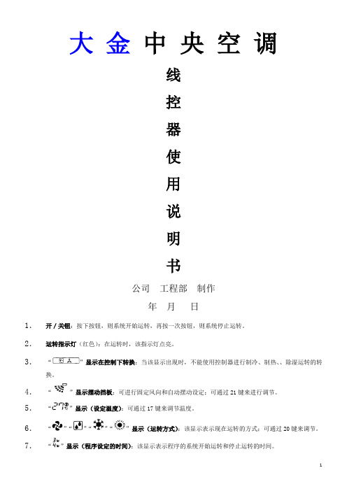
大金中央空调线控器使用说明书公司工程部制作年月日1.开/关钮:按下按钮,则系统开始运转,再按一次按钮,则系统停止运转。
2.运转指示灯(红色):在运转时,该指示灯点亮。
3.“”显示在控制下转换:当该显示出现时,不能使用控制器进行制冷、制热、、除湿运转的转换。
4.“”显示摆动挡板:可进行固定风向和自动摆动设定;可通过21键来进行调节。
5.“”显示(设定温度):可通过17键来调节温度。
6.“”“”“”“”显示(运转方式):该显示表示现在运转的方式;可通过20键来调节。
7.“”显示(程序设定的时间):该显示表示程序的系统开始运转和停止运转的时间。
8.“”显示(检验/试运转):当按下检验/试运转按钮时,该显示表示系统现在的运转方式。
9.“”显示(处于集中控制之下):当该显示出现时,表示系统处于集中控制之下(本显示不是标准规格)。
10.“”显示(送风速度):该显示表示风扇的速度,“低”或“高”。
11.“”显示(空气滤尘网清扫时期):请参照室内机附带的使用说明书。
12.“”显示(除霜/热起动):⑴除霜运转随着室外机盘管上凝结的冰霜增多,制热效果将降低,系统将自动进入除霜运转;室内机风扇停止运转,控制器上显示“”(除霜/热起动);除霜运转6至8分钟(最长10分钟)以后,系统将回到制热运转。
⑵热起动为了防止在制热开始运转时,从室内机吹出冷风,室内机的风扇自动停止运转。
控制器上显示“”(除霜/热起动)。
13.定时器方式启动/停止钮:由专业人员操作。
14.定时器开/关钮:由专业人员操作。
15.检验/运转钮:本按钮仅可由专业的维修人员进行维修时使用!正常运转时请勿使用!16.程序设定时间钮:使用该钮,可设定程序“启动或停止”系统运转的时间。
17.温度设定钮:使用该钮,可设定温度调节器的设定温度。
18.空气滤尘网清扫指示复位钮:请参照室内机附带的使用说明书。
19.风扇速度控制钮:按该钮,可根据您的要求选择风扇的速度,“低”或“高”。
大金中央空调控制器使用说明书
大金中央空调线控器使用说明书公司工程部制作年月日1.开/关钮:按下按钮,则系统开始运转,再按一次按钮,则系统停止运转。
2.运转指示灯(红色):在运转时,该指示灯点亮。
3.“”显示在控制下转换:当该显示出现时,不能使用控制器进行制冷、制热、、除湿运转的转换。
4.“”显示摆动挡板:可进行固定风向和自动摆动设定;可通过21键来进行调节。
5.“”显示(设定温度):可通过17键来调节温度。
6.“”“”“”“”显示(运转方式):该显示表示现在运转的方式;可通过20键来调节。
7.“”显示(程序设定的时间):该显示表示程序的系统开始运转和停止运转的时间。
8.“”显示(检验/试运转):当按下检验/试运转按钮时,该显示表示系统现在的运转方式。
9.“”显示(处于集中控制之下):当该显示出现时,表示系统处于集中控制之下(本显示不是标准规格)。
10.“”显示(送风速度):该显示表示风扇的速度,“低”或“高”。
11.“”显示(空气滤尘网清扫时期):请参照室内机附带的使用说明书。
12.“”显示(除霜/热起动):⑴除霜运转随着室外机盘管上凝结的冰霜增多,制热效果将降低,系统将自动进入除霜运转;室内机风扇停止运转,控制器上显示“”(除霜/热起动);除霜运转6至8分钟(最长10分钟)以后,系统将回到制热运转。
⑵热起动为了防止在制热开始运转时,从室内机吹出冷风,室内机的风扇自动停止运转。
控制器上显示“”(除霜/热起动)。
13.定时器方式启动/停止钮:由专业人员操作。
14.定时器开/关钮:由专业人员操作。
15.检验/运转钮:本按钮仅可由专业的维修人员进行维修时使用!正常运转时请勿使用!16.程序设定时间钮:使用该钮,可设定程序“启动或停止”系统运转的时间。
17.温度设定钮:使用该钮,可设定温度调节器的设定温度。
18.空气滤尘网清扫指示复位钮:请参照室内机附带的使用说明书。
19.风扇速度控制钮:按该钮,可根据您的要求选择风扇的速度,“低”或“高”。
空气净化器的使用教程
空气净化器的使用教程空气净化器是一种能够过滤空气中的污染物和异味,提供更清新、健康的空气环境的电器设备。
它在如今污染严重的现代城市中变得日益重要。
了解如何正确使用空气净化器对于提高家庭、办公室或其他室内空气质量至关重要。
本篇文章将为您提供一份全面的空气净化器使用教程。
1.准备工作在使用空气净化器之前,首先要确保其在一个相对干净、无障碍的地方。
请将其放置在空气流通良好的位置,远离门窗、家具和其他障碍物。
同时,请仔细阅读空气净化器的使用说明书,以便了解其特点、功能和操作方法。
2.启动操作一般而言,空气净化器的操作相对简单。
首先,插上电源线并确保设备连接到可靠的电源上。
然后,打开空气净化器的开关按钮,等待设备启动。
根据具体型号的不同,您可能需要设置空气净化器的工作模式和风速。
一般而言,推荐在自动模式下使用,并根据需要调节风速以达到最佳效果。
3.选择合适的滤网空气净化器通常配备不同类型的滤网,如预过滤网、HEPA滤网和活性炭滤网。
根据空气质量、过敏原类型等因素,选择合适的滤网以确保净化器的效果最大化。
如果您有过敏史或者居住在污染严重的地区,建议选择具有高效过滤功能的HEPA滤网。
4.定期更换滤网滤网的使用寿命有限,根据空气净化器的使用频率和环境条件,滤网的寿命可能在几个月至一年之间。
因此,定期更换滤网对维持净化器的性能至关重要。
请按照生产商的建议定期检查和更换滤网,确保空气净化器的有效运行。
5.保持室内卫生空气净化器能够有效过滤空气中的污染物,但它不能彻底解决所有问题。
保持室内的卫生和整洁同样重要。
请定期清洁地板、家具和其他表面,以去除尘埃、细菌和其他污染物。
此外,定期通风也是提高室内空气质量的有效方法,可以通过打开窗户或使用空气净化器的“自然风”模式来实现。
6.智能化控制功能一些高端的空气净化器配备了智能化控制功能,可以通过手机应用程序或远程控制器进行操作。
这些功能使得您可以根据需要随时调整设置,以及查看室内和室外空气质量的指标。
Daikin 无线手机遥控器操作手册说明书
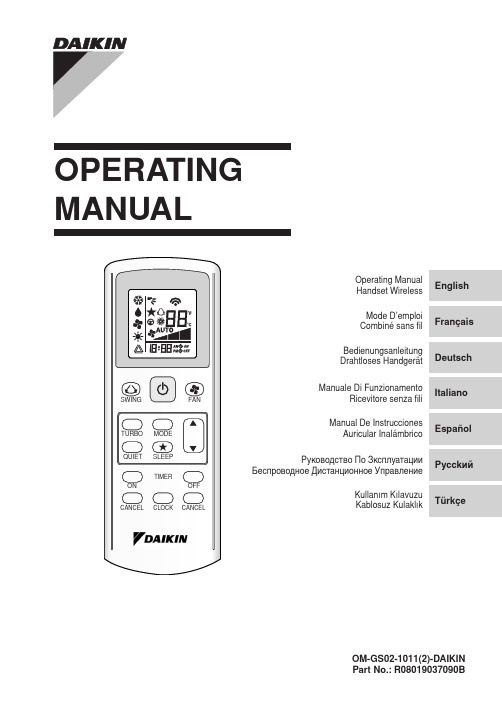
InstallationFaites correspondre l’anneau de l’extrémité de la chaînette à boules avec le trou de vis situé au dos de la télécommande et À xez-le à l’aide de la vis.Fixez le support et la chaînette à boules comme ci-dessus, dans une position permettant une réception facile des signaux de la télécommande.Passez la chaînette à boules à l’arrière du support et faites correspondre l’anneau de l’extrémité de la chaînette à boules avec le trou supérieur du support. Fixez le support au mur à l’aide de 2 vis.InstallationLegen Sie den Ring am Ende der Kugelkette auf die Schraubbohrung an der Rückseite der Fernbedienung und befestigen Sie ihn mit der Schraube.Montieren Sie die Halterung und die Kugelkette wie oben gezeigt an der Stelle, an der Signale von der Fernbedienung gut empfangen werden können.Führen Sie die Kugelkette durch die Rückseite der Halterung und legen Sie den Ring am Kettenende auf das obere Loch in der Halterung. Befestigen Sie die Halterung mit 2 Schrauben an der Wand.InstallazioneFar combaciare l’anello all’estremità della catena a sfera con il foro della vite sul retro del telecomando e À ssare bene con la vite.Fissare il supporto e la catena a sfera al di sopra del punto in cui possono essere ricevuti facilmente i segnali dal telecomando.Far passare la catena a sfera attraverso il retro del supporto e far combaciare l’anello all’estremità della catena con il foro superiore del supporto. Fissare il supporto alla parete mettendo 2 viti attraverso di esso.1.2.3.1.2.3.1.2.3.InstalaciónUna el anillo del À nal de la cadena de bolas con el agujero del tornillo de la parte trasera del control remoto y fíjelo con el tornillo.Coloque el soporte y la cadena de bolas, como indica la imagen superior, en una posición en que las señales del control remoto se puedan recibir con facilidad.Pase la cadena de bolas por la parte trasera del soporte y una el anillo del À nal de la cadena de bolas con el agujero superior del soporte. Fije el soporte en la pared colocando 2 tornillos a través del soporte.МонтажСоотнесите кольцо на конце шариковой цепи с винтовым отверстием в задней части пульта дистанционного управления и закрепите его с помощью винта.Прикрепите держатель и шариковую цепь, как показано выше, в положении, где обеспечивается легкий прием сигнала ПДУ.Проденьте шариковую цепь через заднюю часть держателя и соотнесите кольцо на конце шариковой цепи с верхним отверстием держателя. Прикрепите держатель к стене с помощью 2 винтов.MontajZincirin sonundaki halkayla uzaktan kumandan›n arkas›ndaki vida deli¤ini efllefltirin ve vidayla sabitleyin.Tutucu ve zinciri uzaktan kumandadan gelen sinyallerin kolayca al›nabilece¤i yerin üzerine yerlefltirin.Zinciri tutucunun arkas›ndan geçirin ve zincirin sonundaki halkay› tutucunun üst deli¤i ile efllefltirin. Tutucuyu her iki viday› içinden geçirerek duvara sabitleyin.1.2.3.1.2.3.1.2.3.MEMO / LE MÉMO / MITTEILUNG / PROMEMORIA / EL MEMORÁNDUM / ПАМЯТКА/ NOT。
大金ACK70N操作说明书

各部名称湿度センサー:湿度感应部操作パネル:控制面板前面表示ランプ:前指示灯前面パネル:前面板吸込口:进风口取っ手:提手吹出口:出风口ルーバー:顶盖アクティブプラズマイオン発生ユニット:离子净化发生部(内部)機種名製造番号:制造号電源コード:电源线電源プラグ:插头前面パネル:前面板プレフィルター:前置滤网脱臭フィルター:除臭滤网集塵フィルター:集尘滤网ユニット1(プラズマイオン化部):滤芯(离子化部)ユニット2(ストリーマユニット):滤芯2(流光净化部)ニオイセンサー:异味感应器ホコリセンサー:灰尘感应器安全ガード:安全网加湿フィルターユニット:加湿滤芯水タンク:水箱加湿トレー:加湿托盘送風ファン:风扇フロート:卡扣(禁止拆卸)銀イオンカートリッジ:银离子感应芯片使用前的准备前面指示灯お知らせランプ:提示灯。
与滤芯1,2和加水指示灯同时亮。
ハウスダスト:灰尘指示灯。
分为绿色,橙色,红色。
正常时为绿色,中等灰尘为橙色,严重为红色。
(开后7秒内一直为绿色,是检测中)ニオイ:异味指示灯。
分为绿色,橙色,红色。
正常为绿色,中等为橙色,严重为红色。
插拔电源和重按前面板后,开机第一分钟内显示为绿色。
水除菌中:加湿工作时会亮。
現在湿度目安(%):现在湿度指示器。
表示范围20%到90%之间。
低于20%时,显示为20。
高于90%时,显示为90%。
控制面板ユニット1洗浄:滤芯1需要清洗时会亮ユニット2洗浄:滤芯2需要清洗时会亮給水:水箱没有水时会亮(没有水时,空气净化机也可以单独使用)会有PPP的提示音2秒押し:长按两秒{表示ランプ(明暗切)}控制面板会锁住,可以仿制小孩误操作表示ランプ(明暗切):指示灯亮度调节键,分别是亮,暗,关闭。
切タイマー:定时关机键,按一下是1小时,两下是两小时,三下是4小时,四下是停止定时关机,相应指示灯会亮。
入タイマー:定时开机键,按一下是4小时后,两下是6小时后,三下是8小时后,四下是停止定时开机,相应指示灯会亮。
大金空调使用指南
大金空调使用指南尊敬的业主:您好!感谢您使用大金空调,您选购的大金空调我们已为您安装、调试完毕,从现在起您就可以享受大金空调为您带来的舒适和温馨了。
这里,我们主要向您介绍一些大金空调在使用过程中需要注意的事项,以方便您的使用。
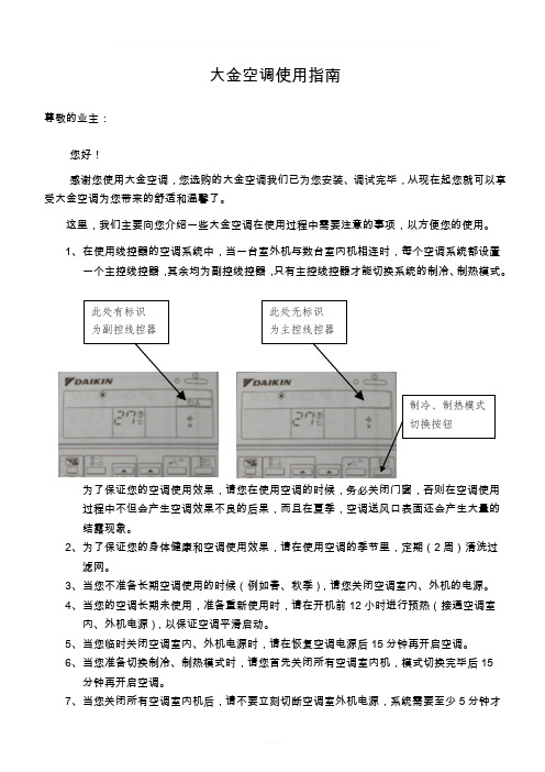
1、 在使用线控器的空调系统中,当一台室外机与数台室内机相连时,每个空调系统都设置一个主控线控器,其余均为副控线控器,只有主控线控器才能切换系统的制冷、制热模式。
为了保证您的空调使用效果,请您在使用空调的时候,务必关闭门窗,否则在空调使用过程中不但会产生空调效果不良的后果,而且在夏季,空调送风口表面还会产生大量的结露现象。
2、 为了保证您的身体健康和空调使用效果,请在使用空调的季节里,定期(2周)清洗过滤网。
3、 当您不准备长期空调使用的时候(例如春、秋季),请您关闭空调室内、外机的电源。
4、 当您的空调长期未使用,准备重新使用时,请在开机前12小时进行预热(接通空调室内、外机电源),以保证空调平滑启动。
5、 当您临时关闭空调室内、外机电源时,请在恢复空调电源后15分钟再开启空调。
6、 当您准备切换制冷、制热模式时,请您首先关闭所有空调室内机,模式切换完毕后15分钟再开启空调。
7、 当您关闭所有空调室内机后,请不要立刻切断空调室外机电源,系统需要至少5分钟才能使空调系统完全回复到关机状态,立即关闭电源会导致漏水或故障。
8、 在制热模式下开启空调时,空调室内机可能不会立刻运转或吹冷风,需等待5~15分钟在主机正式运转前系统需对主机的各个组件进行自动预热。
10、在制热运转过程中,系统可能会停止制热几分钟,那不是空调故障,是空调室外机在进行化霜运转。
系统在进行化霜运转时,线控器上有标识显示。
11、当空调室内机运行一定时间后,系统会显示标识提醒您清洗回风过滤网,您清洗完过滤网后,按“滤网清洗复位”按钮就可以继续正常使用了。
12、当您刚开始使用空调时,如果您需要快速降低室内温度,可使用风速按钮调节风量,最大风量时,线控器液晶显示屏上将会显示“H ”。
家用空气净化器使用说明书
家用空气净化器使用说明书使用说明书一、产品简介家用空气净化器是一种能够过滤空气中的污染物,并提供清新、干净空气的设备。
本产品采用先进的空气净化技术,能够有效地去除空气中的颗粒物、有害气体和异味,为您提供健康舒适的室内环境。
二、产品特点1. 多功能过滤系统:本产品配备了高效HEPA过滤器、活性炭吸附层和负离子发生器,可以彻底过滤空气中的微尘、细菌、病毒、有害气体等污染物。
2. 低噪音设计:采用静音技术,运行过程中噪音低于30分贝,不会干扰您的休息和工作。
3. 多档调节:具备多种风速档位,可根据室内空气质量的不同需求进行调节。
4. 智能传感器:内置空气质量感应器,可自动检测室内空气质量的变化,并根据需要调整工作模式,保障空气的清洁度。
5. 持久耐用:采用优质材料和稳定的结构设计,保证产品的使用寿命和性能稳定性。
三、使用方法1. 安装:将空气净化器放置在通风良好的室内位置,并接通电源。
2. 电源开关:按下电源开关,指示灯亮起,表示设备已经开始运行。
3. 风速调节:通过调节风速按钮,将风速档位调至适当位置。
一般情况下,室内空气质量较好时,可以选择较低的档位;而在空气质量较差的情况下,可以调至较高的档位以加强过滤效果。
4. 定时功能:如需设置定时开关机功能,可以按下定时按钮,根据需要进行相应设置。
5. 滤网更换:根据产品说明书的指引,定期检查和更换滤网,以保证净化器的过滤效果和使用寿命。
四、注意事项1. 请勿将本产品暴露于潮湿、高温或者极低温的环境中,以免影响性能和寿命。
2. 请保持插座和电源线的清洁和干燥,避免积水、灰尘等的积累。
3. 请定期清洁产品外壳和滤网,以保持其良好的工作状态。
4. 当设备长时间不使用时,请及时拔除电源插头,并将设备置于干燥通风处存放。
5. 请勿私自拆卸或修理本产品,如需维修,请联系专业人士或售后服务中心。
五、售后服务如在使用过程中遇到任何问题,请联系我们的售后服务中心,我们将为您提供及时的维修和技术支持。
家用空气净化器操作手册

家用空气净化器操作手册一、简介家用空气净化器是一种能够净化室内空气,提供健康安全环境的电器设备。
本操作手册旨在帮助用户正确操作和使用家用空气净化器,以获得更好的空气质量和使用体验。
二、净化器外观及部件1. 外观家用空气净化器外观一般由主机、控制面板、空气出风口等部分组成。
主机通常为方形或圆柱形状,具有美观大方的设计。
2. 控制面板控制面板用于设置净化器的工作模式、调节风速等。
常见的控制按钮和显示器包括开/关机按钮、风速调节按钮、定时设置按钮、工作模式设置按钮等。
3. 空气出风口空气出风口用于释放被净化后的空气,通常位于净化器的正面或侧面。
三、净化器使用步骤1. 确定使用场所在选择使用家用空气净化器前,需要考虑使用的场所大小和污染程度。
一般来说,较小的空间可选择较小功率的净化器,而较大的空间则需要选择功率较大的净化器。
2. 连接电源将净化器的电源线插入电源插座,并确保电源供应正常。
如果家用空气净化器配备有电池,也可以选择使用电池供电。
3. 控制面板设置根据自身需求,设置工作模式、风速、定时等功能。
通常可以选择自动模式、静音模式、强力模式等不同工作模式。
4. 开启净化器按下开/关机按钮开启净化器。
净化器开始工作时,可以听到风机运转的声音。
5. 调整风速根据需要,可适时调整净化器的风速。
较高的风速能够更快速地净化室内空气,而较低的风速则更为安静舒适。
6. 定时设置若需要在特定时间段内自动关闭净化器,可设置定时功能。
净化器会在设定的时间到达后自动关闭。
四、净化器维护与清洁1. 定期更换滤芯滤芯是空气净化器的核心部件,需要定期更换以保证净化效果。
一般情况下,滤芯建议每3-6个月更换一次,具体时间可根据使用环境和使用频率进行调整。
2. 清洁净化器外壳定期使用干净柔软的布清洁净化器外壳,并避免使用含有酸性和腐蚀性的清洁剂。
确保净化器外观整洁,不影响美观和运行效率。
3. 注意安全使用在清洁净化器或更换滤芯时,务必先拔掉电源插头,避免触电和其他安全问题。
室内空气净化器使用手册

室内空气净化器使用手册一、产品介绍室内空气净化器是一种用于净化室内空气的设备,能够去除空气中的颗粒物、异味和有害物质,提供清洁、健康的室内空气环境。
本手册将详细介绍室内空气净化器的使用方法和注意事项,帮助用户正确使用和维护设备。
二、使用准备1. 选择合适的位置:将空气净化器放置在离墙壁和家具约30厘米的距离内,确保空气流动良好。
2. 接通电源:将电源线插入室内电源插座,并确保供电稳定。
3. 清洁滤网:在首次使用前,请按照说明书清洁滤网,并进行必要的滤网更换。
三、操作说明1. 开关机:按下电源按钮,设备启动,指示灯亮起,空气净化器开始工作。
再次按下电源按钮,设备关闭。
2. 模式选择:根据需要,选择合适的净化模式。
通常有自动模式、睡眠模式和强力模式可选。
3. 风速调节:根据室内空气质量需要,调节风速档位,一般有低、中、高三档可选。
4. 定时功能:根据个人需要,设置定时功能,在预定的时间内自动关闭或开启空气净化器。
5. 过滤器更换提醒:根据设备所配备的指示灯或音频提示,及时更换过滤器,确保净化效果持续优良。
四、使用注意事项1. 保持通风:在使用空气净化器的同时,确保室内有良好的通风,可开窗换气,提高空气流通效果。
2. 长时间使用:如需长时间使用空气净化器,请关闭门窗,确保室内空气循环清洁。
3. 防尘保养:定期清理设备表面和滤网,防止灰尘和污垢堆积影响净化效果。
4. 水质要求:对于带加湿功能的空气净化器,请使用纯净水或蒸馏水,避免水垢对设备产生影响。
5. 定期更换滤网:滤网使用一段时间后会积累过多的颗粒物,建议按照说明书要求定期更换,以保证净化效果和设备寿命。
五、故障排除1. 电源故障:若设备无法启动,请检查电源线是否插紧或更换电源插座尝试。
2. 异常噪音:若设备工作时发出异常噪音,请检查是否有杂物或故障部件引起,如无法排除请咨询售后服务。
3. 净化效果下降:若空气净化效果明显下降,请检查滤网是否需要更换或清洁。
家用空气净化器用户手册
家用空气净化器用户手册使用家用空气净化器用户手册1.产品介绍家用空气净化器是一款用于净化室内空气的设备,有效去除空气中的细菌、病毒、灰尘等有害物质,为您提供洁净健康的室内空气环境。
本手册将为您详细介绍净化器的使用方法和注意事项,请您仔细阅读并按照指导操作。
2.安装使用2.1 净化器的安装将净化器放置在室内通风良好的位置,确保周围没有遮挡物。
将电源线插入插座,确保电源线不被拉扯或压到重物上。
注意避免触摸电源线或插头带电的部分,以免发生电击事故。
2.2 净化器的开关按下净化器面板上的开关键,净化器将启动并开始工作。
可以调节风速档位,根据室内空气污染程度选择适当的档位,高速档位使用于严重污染的环境,低速档位适用于一般清洁的环境。
3.使用注意事项3.1 安全使用使用过程中,请确保净化器稳固放置,避免碰撞、倾倒或受到外力撞击。
离开房间或长时间不使用时,建议将净化器关闭并拔掉电源插头。
3.2 定期清洁定期清洁空气净化器非常重要,可以延长其使用寿命并保持良好的净化效果。
请按照说明书进行清洁步骤,注意断开电源并使用清洁剂和软布进行清洁。
不要用水直接清洗净化器,以免发生电气故障。
3.3 滤芯更换净化器的滤芯是净化空气的核心部件,随着使用时间的增长,滤芯会逐渐堵塞,影响净化效果。
请定期检查滤芯的状态,根据使用情况及时更换新的滤芯。
请确保选购的滤芯与您所使用的净化器型号相匹配。
4.故障排除4.1 故障现象:净化器无法正常启动。
解决方法:检查电源插头是否插紧,确保供电正常;检查是否按下开关键。
4.2 故障现象:净化器工作时产生异常噪音。
解决方法:检查是否有异物掉入净化器内部,及时清除;如问题依旧,请联系售后服务中心。
5.保养与维修5.1 保养方法定期进行清洁和滤芯更换,保持净化器的良好工作状态。
在清洁和维修之前,请务必切断电源并等待几分钟,以免触电事故。
5.2 维修服务如发现净化器出现故障或需要维修时,请联系售后服务中心,由专业人员进行检修和维护。
空气净化器说明书
空气质量
进风机
排风机
负氧离子
紫外杀毒
0-25
优
关
关
关
关
25-75
良
低速
开
关
关
75-115
轻度污染
低速
开
开
开
11Hale Waihona Puke -150中度污染中速
开
开
开
>150
重度污染
高速
开
开
开
自动模式下,按控制面板上的任一负载对应的按键,系统自动切换到手动模式,手动模式优先于自动模式执行。
按红外遥控器上的“自动”按键,系统切换到自动模式下运行。
当指示灯3点亮时表示负氧离子发生器开,否则为负氧离子发生器关。
当指示灯4点亮时表示紫外杀毒(菌)开,否则为紫外杀毒(菌)关。
TVOC浓度显示
3格亮时表示轻度污染。
6格亮时表示中度污染。
9格亮时表示重度污染。
不亮时表示无TVOC污染。
风速显示
3格亮时表示进风机风速为低速。
6格亮时表示进风机风速为中速。
9.无有效三包凭证及有效发票的(能够证明该商品在三包有效期内的除外);
10.因不可抗力造成损坏的。
空气净化器说明书(总15页)
专利产品 仿冒必究
安阳振动器有限责任公司(集团)
为确保产品的正确、安全使用,请在使用前仔细阅读本说明书
产品简介
◆ 产品简介.................................................................................1
二、以下情况不执行三包政策:
1.超过三包有效期的;
Daikin 环保氧氮系列空调产品说明书
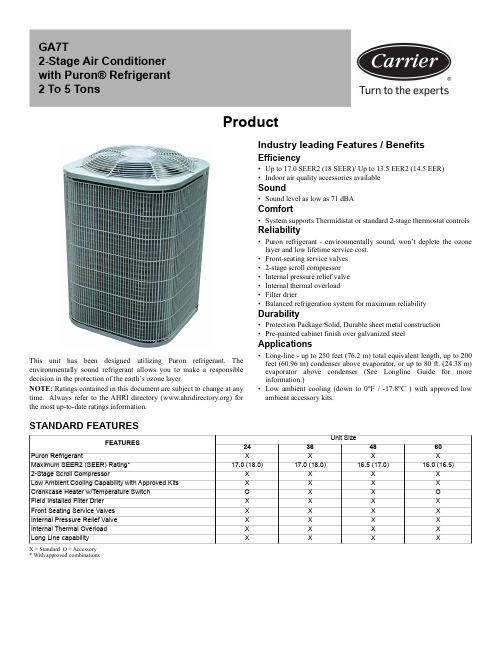
ProductThis unit has been designed utilizing Puron refrigerant. The environmentally sound refrigerant allows you to make a responsible decision in the protection of the earth’s ozone layer.NOTE: Ratings contained in this document are subject to change at any time. Always refer to the AHRI directory () for the most up-to-date ratings information.Industry leading Features / BenefitsEfficiency •Up to 17.0 SEER2 (18 SEER)/ Up to 13.5 EER2 (14.5 EER)•Indoor air quality accessories available Sound•Sound level as low as 71 dBAComfort•System supports Thermidistat or standard 2-stage thermostat controlsReliability•Puron refrigerant - environmentally sound, won’t deplete the ozone layer and low lifetime service cost.•Front-seating service valves •2-stage scroll compressor •Internal pressure relief valve •Internal thermal overload •Filter drier•Balanced refrigeration system for maximum reliabilityDurability•Protection Package:Solid, Durable sheet metal construction •Pre-painted cabinet finish over galvanized steelApplications•Long-line - up to 250 feet (76.2 m) total equivalent length, up to 200feet (60.96 m) condenser above evaporator, or up to 80 ft. (24.38 m)evaporator above condenser (See Longline Guide for more information.)•Low ambient cooling (down to 0°F / -17.8°C ) with approved low ambient accessory kits.X = Standard O = Accessory * With approved combinationsGA7T2-Stage Air Conditioner with Puron® Refrigerant 2 To 5 TonsSTANDARD FEATURESFEATURESUnit Size24364860Puron RefrigerantXXXXMaximum SEER2 (SEER) Rating*17.0 (18.0)17.0 (18.0)16.5 (17.0)16.0 (16.5)2-Stage Scroll CompressorX X X X Low Ambient Cooling Capability with Approved Kits X X X X Crankcase Heater w/Temperature Switch O X X O Field Installed Filter Drier X X X X Front Seating Service Valves X X X X Internal Pressure Relief Valve X X X X Internal Thermal Overload X X X X Long Line capabilityXXXXAHRI RATINGSFor AHRI ratings certificates, please refer to the AHRI directory Additional ratings and system combinations can be accessed via the Ratings Database here: MODEL NUMBER NOMENCLATURE12345678, 9101112G A 7T A N 42400W BrandingOD TypeSEER2OD Design TypeMajor SeriesVoltageRefrigerantNominal Capacity FeatureSpecial FeatureRegion G = Generic A = AC7 = 17 SEER2T =2-Stage A-Z = Major Iteration N = 208-230-1or 208/230-1P = 208-230-3or 208/230-3E = 460-34 = R410A24 = 24,000 BTUH (2 Tons)36 = 36,000 BTUH (3 Tons)48 = 48,000 BTUH (4 Tons)60 = 50,000 BTUH (5 Tons)0 = Standard 0 =StandardW = Standard SouthwestACCATALOG ORDERING NUMBERSSize Model Ordering Number24GA7TAN42400W 36GA7TAN43600W 48GA7TAN44800W 60GA7TAN46000WPHYSICAL DATAUNIT SIZE24364860Compressor Type Scroll REFRIGERANT PuronControlTXV (Puron® Hard Shutoff) Charge lb (kg) 6.03 (2.74)10.3 (4.67)12.22 (5.54)9.27 (4.20)COND FAN Propeller Type, Direct DriveAir Discharge VerticalAir Qty (CFM)2640283047794779 Motor HP 1/121/121/41/4 Motor RPM 800800800800COND COILFace Area (Sq ft)19.320.125.125.1 Fins per In.25202020 Rows 1222 Circuits5877VALVE CONNECT. (In. ID) Vapor 3/47/87/87/8Liquid3/8"REFRIGERANT TUBES* (In. OD) Rated Vapor(0-80 Ft Tube Length)3/47/81 1/81 1/8Liquid (0-80 Ft Tube Length)3/8"REFRIGERANT PIPING LENGTH LIMITATIONSLiquid Line Sizing and Maximum Total Equivalent Lengths† for Cooling Only Systems with R-410APuron® Refrigerant:The maximum allowable length of a residential split system depends on the liquid line diameter and vertical separation between indoor and outdoor units.See Table below for liquid line sizing and maximum lengths :Table 1 – Maximum Total Equivalent LengthOutdoor Unit BELOW Indoor Unit* Maximum actual length not to exceed 200 ft (61 m)†Total equivalent length accounts for losses due to elbows or fitting. See the Long Line Guideline for details. -- = outside acceptable range* Maximum actual length not to exceed 200 ft (61 m)†Total equivalent length accounts for losses due to elbows or fitting. See the Long Line Guideline for details.Units are factory charged for 15 ft (4.6 m) of 3/8” liquid line. The factory charge for 3/8” lineset 9 oz.(266.16 g). When using other length or diameter liquid lines, charge adjustments are required per the chart above.Charging Formula:[(Lineset oz/ft x total length) – (factory charge for lineset)] = charge adjustmentExample 1: System has 15 ft of line set using existing 1/4“ liquid line. What charge adjustment is required? Formula:(.27 oz/ft x 15ft) – (9 oz) = (-4.95) oz.Net result is to remove 4.95 oz of refrigerant from the systemExample 2: System has 45 ft of existing 5/16” liquid line. What is the charge adjustment?Formula:(.40 oz/ft. x 45ft) – (9 oz.) = 9 oz.Net result is to add 9 oz of refrigerant to the systemNOTE: Conditions must be favorable for charging by subcooling method. Indoor temperature must be 70°F to 80°F (21.1°C to 26.7°C), and outdoor temperature must be 70°F to 100°F (21.1°C to 37.8°C). If outside these conditions, adjust charge for long line sets by weigh-in method.SizeLiquid Line ConnectionLiquid Line Diam.w/TXV AC with Puron Refrigerant Maximum Total Equivalent Length†: Outdoor unit BELOW IndoorVertical Separation ft (m)0-5(0-1.5)6-10(1.8-3.0)11-20(3.4-6.1)21-30(6.4-9.1)31-40(9.4-12.2)41-50(12.5-15.2) 51-60(15.5-18.3)61-70(18.6-21.3)71-80(21.6-24.4)24 3/81/4 7575755050--------5/16250*250*250*250*250*225*1751251003/8250*250*250*250*250*250*250*250*250*36 3/85/1617515015010010010075----3//8250*250*250*250*250*250*250*250*250*483/83/8250*250*250*250*250*250*230160--603/83/8250*250*250*225*190150110----Table 2 – Maximum Total Equivalent LengthOutdoor Unit ABOVE Indoor UnitSizeLiquid LineConnectionLiquid LineDiam.w/TXVAC with Puron Refrigerant Maximum Total Equivalent Length †:Outdoor unit ABOVE Indoor Vertical Separation ft (m)25(7.6)26-50(7.9-15.2)51-75(15.5-22.9)76-100(23.2-30.5)101-125(30.8-38.1)126-150(38.4-45.7)151-175(46.0-53.3)176-200(53.6-61.0)243/81/4100125175200225*250*250*250*5/16250*250*250*250*250*250*250*250*3/8250*250*250*250*250*250*250*250*363/85/16225*250*250*250*250*250*250*250*3/8250*250*250*250*250*250*250*250*483/83/8250*250*250*250*250*250*250*250*603/83/8250*250*250*250*250*250*250*250*Table 3 – Refrigerant Charge AdjustmentsLiquid Line SizePuron Charge oz/ft (g/m)3/80.60 (17.74)(Factory charge for lineset = 9 oz / 266.16 g)5/160.40 (11.83)1/40.27 (7.98)LONG LINE APPLICATIONSAn application is considered Long Line, when the refrigerant level in the system requires the use of accessories to maintain acceptable refrigerant management for systems reliability. See Accessory Usage Guideline table for required accessories. Defining a system as long line depends on the liquid line diameter, actual length of the tubing, and vertical separation between the indoor and outdoor units. For Air Conditioner systems, the chart below shows when an application is considered Long Line.NOTE: See Residential Piping and Long Line Guideline for detailsVAPOR LINE SIZING AND COOLING CAPACITY LOSSAcceptable vapor line diameters provide adequate oil return to the compressor while avoiding excessive capacity loss. The suction line diameters shown in the chart below are acceptable for AC systems with Puron refrigerant:* Units are rated with 25 ft (7.6 m) of lineset length. See Vapor Line Sizing and Cooling Capacity Loss table when using other sizes and lengths of lineset.Table 4 – AC with Puron Refrigerant Long Line Description ft (m) Beyond these lengths, a TXV is requiredTotal LengthOutdoor Unit Above or Below Indoor UnitTXV required beyond 50 ft. (15.2 m)TXV required beyond 20 ft. (6.1 m)Table 5 – AC with Puron Refrigerant Long Line Description ft (m) (Beyond these lengths, long line accessories are required)Liquid Line Size Units On Same LevelOutdoor Below Indoor Outdoor Above Indoor1/4 + TXV No accessories needed within allowedlengths No accessories needed withinallowed lengths175 (53.3) 5/16 + TXV 120 (36.6)50 (15.2) vertical or 120 (36.6) total 120 (36.6) 3/8 + TXV80 (24.4)35 (10.7) vertical or 80 (24.4) total80 (24.4)Table 6 – Vapor Line Sizing and Cooling Capacity Losses — Puron Refrigerant 2-Stage Air Conditioner ApplicationsUnit Nominal Size (Btuh)Maximum Liquid Line Diameters (In. OD)Vapor Line Diameters(In.) ODCooling Capacity Loss (%)Total Equivalent Line Length ft. (m)26-50 (7.9-15.2)51-80 (15.5-24.4)81-100(24.7-30.5)101-125 (30.8-38.1)126-150 (38.4-45.7)151-175 (46.0-50.3)176-200 (53.6-60.0)201-225 (61.3-68.6)226-250(68.9-76.2)243/85/80112334453/4000011111363/85/8124567910113/40011223347/8000011112483/83/41223456777/80112223331-1/800———————603/83/4124567910117/80122344551-1/8000111111Applications in this area may be long line and may have height restrictions. See the Residential Piping and Long Line Guideline.— Applications in this area are not recommended due to insufficient oil return* Permissible limits of the voltage range at which the unit will operate satisfactorily † Time-Delay fuse.FLA - Full Load Amps LRA - Locked Rotor Amps MCA - Minimum Circuit Amps RLA - Rated Load AmpsNOTE : Control circuit is 24-V on all units and requires external power source. Copper wire must be used from service disconnect to unit.All motors/compressors contain internal overload protection.Complies with 2010 requirements of ASHRAE Standards 90.1NOTE : Tested in compliance with AHRI 270 but not listed with AHRI.Electrical DataUNIT SIZEV/PHOPER VOLTS*COMPR FAN MCA MAX FUSE†orCKT BRK AMPSMAXMINLRA RLA FLA 24208-230/125319761.010.90.4314.0203692.015.40.5019.83548126.519.9 1.2026.14060158.025.61.2033.250A-WEIGHTED Sound SOUND POWER LEVEL (dBA) w/o ACCESSORY SOUND SHIELDUNIT SIZESTANDARD RATINGTYPICAL OCTAVE BAND SPECTRUM (without tone adjustment)12525050010002000400080002473 - High Stage 63.463.465.466.562.158.654.473 - Low Stage 62.062.862.864.059.958.151.53674 - High Stage 74.269.464.963.961.259.755.974 - Low Stage 73.371.065.663.761.259.957.04875 - High Stage 67.566.068.969.663.459.755.574 - Low Stage 68.368.968.469.262.658.853.56075 - High Stage 66.367.767.969.363.361.559.474 - Low Stage68.565.367.667.763.960.556.0A-WEIGHTED Sound SOUND POWER LEVEL (dBA) WITH ACCESSORY SOUND SHIELDUNIT SIZESTANDARD RATINGTYPICAL OCTAVE BAND SPECTRUM (without tone adjustment)12525050010002000400080002472- High Stage 62.962.162.562.158.252.947.672 - Low Stage 62.162.862.862.258.355.248.43672 - High Stage 74.068.965.662.860.859.154.972 - Low Stage 73.471.165.562.660.659.155.54872 - High Stage 68.765.567.368.161.857.652.071 - Low Stage 68.866.667.266.862.458.352.16074 - High Stage 67.566.767.668.461.258.054.172 - Low Stage68.566.166.765.762.558.653.7Charging Subcooling (TXV-Type Expansion Device)UNIT SIZEREQUIRED SUBCOOLING °F (°C)249 (5.0)3611 (6.1)4811 (6.1)609 (5.0)X = Accessory* For tubing line sets between 80 and 200 ft. (24.38 and 60.96 m) and/or 20 ft. (6 m) vertical differential, refer to Residential Piping and Longline Guideline.Accessory Description and Usage (Listed Alphabetically)1. Crankcase HeaterAn electric resistance heater which mounts to the base of the compressor to keep the lubricant warm during off cycles. Improves compressor lubrication on restart and minimizes the chance of liquid age Guideline:Required in low ambient cooling applications.Required in long line applications.Suggested in all commercial applications.2. Evaporator Freeze ThermostatAn SPST temperature-actuated switch that stops unit operation when evaporator reaches freeze-up age Guideline:Required when low ambient kit has been added.3. Liquid-Line Solenoid Valve (LLS)An electrically operated shutoff valve which stops and starts refrigerant liquid flow in response to compressor operation. It is to be installed at the outdoor unit to control refrigerant off cycle migration in the heating mode.Usage Guideline:An LLS is required in all long line heat pump applications to control refrigerant off cycle migration inthe heating mode. See Long Line Guideline.Suggested for all commercial applications.4. Low-Ambient Pressure SwitchA long life pressure switch which is mounted to outdoor unit service valve. It is designed to cycle the outdoor fan motor in order to maintain head pressure within normal operating limits. The control will maintain working head pressure at low-ambient temperatures down to 0°F (-17.8°C) when properly installed.Usage Guideline:A Low-Ambient Pressure Switch must be used when cooling operation is used at outdoor temperatures below 55°F (12.8°C). 5. Thermostatic Expansion Valve (TXV)A modulating flow-control valve which meters refrigerant liquid flow rate into the evaporator in response to the superheat of the refrigerant gas leaving the evaporator.Kit includes valve, adapter tubes, and external equalizer tube. Hard shut off types are available.NOTE: When using a hard shut off TXV with single phase reciprocating compressors, a Compressor Start Assist Capacitor and Relay is required. Usage Guideline:Required to achieve AHRI ratings in certain equipment combinations.Refer to combination ratings.Hard shut off TXV or LLS required in air conditioner long line applications.6. Winter Start ControlThis control is designed to alleviate nuisance opening of the low-pressure switch by bypassing it for the first 3 minutes of operation.AccessoriesKIT NUMBER KIT NAME24364860KSAFT0101AAA Evaporator Freeze Stat X X X X KAATD0101TDR Time Delay Relay X X X X KSALA0301410Low Ambient X X X X KSALA1001AAA MotorMaster X X X X KSAHS2501AAA Hard Start X X KSAHS2801AAA Hard StartX X KSACY0101AAA Cycle Protection X X X X KSASF0201AAA Support Feet X X X X KAALS0201LLS Solenoid Valve X X X X KAAWS0101AAA Winter StartX X X X KAACH1701AAA Crankcase Heater X SKAACH1601AAA Crankcase HeaterSXKSATX0201PUR TXV KIT (for use with copper coils)XKSATX0301PUR TXV KIT (for use with copper coils)XKSATX0401PUR TXV KIT (for use with copper coils)XXKSBTX0201PUR TXV KIT (for use with aluminum coils)XKSBTX0301PUR TXV KIT (for use with aluminum coils)XKSBTX0401PUR TXV KIT (for use with aluminum coils)XX KSASH2301COP Sound Blanket X X KSASH2401COP Sound BlanketX X KAALP0401PUR Pressure Switch Low X X X X KAAHI0501PURPressure Switch HighXXXX ACCESSORY USAGE GUIDELINEAccessoryRequired for Low Ambient Cooling Applications (Below 55°F / 12.8°C)Required for Long Line Applications*Required for Sea Coast Applications(within 2 miles/3.2 km)Ball Bearing Fan Motor StandardStandardStandard Crankcase HeaterYes (standard on some units)Yes (standard on some units)No Evaporator Freeze Thermostat YesNoNoHard Shutoff TXV Yes(standard w/factory approvedindoor unit)Yes(standard w/factory approvedindoor unit)Yes(standard w/factory approvedindoor unit)Liquid Line Solenoid Valve No See Residential Piping and Long Line GuidelineNo Low-Ambient Control Yes No No Winter Start ControlYesNoNoGA7T: ProductManufacturer reserves the right to change, at any time, specifications and designs without notice and without obligations.13Condenser Only Ratings*SST °F (°C)CONDENSER ENTERING AIR TEMPERATURES °F (°C)55.0 (12.8)65.0 (18.3)75.0 (23.9)85.0 (29.4)95.0 (35.0)105.0 (40.6)115.0 (46.1)30.0 (-1.1)TCG 20.0919.1018.0716.9915.8614.7113.52SDT 67.0276.6386.2195.77105.31114.76124.12KW 0.93 1.08 1.23 1.40 1.57 1.77 2.0035.0 (1.7)TCG 22.1821.1119.9918.8217.6016.3315.03SDT 68.0277.6087.1596.67106.17115.64124.96KW 0.92 1.08 1.23 1.40 1.58 1.78 2.0140.0 (4.4)TCG 24.4123.2622.0720.8019.4818.0916.65SDT 69.1378.6788.1497.65107.06116.46125.85KW 0.91 1.07 1.23 1.40 1.58 1.79 2.0245.0 (7.2)TCG 26.8125.5924.2822.9121.4919.9918.46SDT 70.3479.7689.2398.67108.01117.36126.44KW 0.90 1.06 1.23 1.40 1.59 1.80 2.0250.0 (10.0)TCG 29.4028.0826.6825.1823.6122.0220.31SDT 71.4580.8890.2899.72109.15118.25127.57KW 0.88 1.05 1.22 1.40 1.60 1.80 2.0455.0 (12.8)TCG 32.1630.7329.2227.6125.9224.1622.32SDT 72.7382.1291.44100.80110.10119.35128.53KW 0.86 1.04 1.22 1.40 1.60 1.822.0630.0 (-1.1)TCG 13.6913.1912.5911.8610.999.998.86SDT 63.5273.3283.0792.75102.36111.87121.33KW 0.680.790.91 1.04 1.19 1.36 1.5535.0 (1.7)TCG 15.3314.7314.0413.2412.3111.2910.10SDT 64.3174.0683.7793.42103.08112.47121.97KW 0.650.770.89 1.03 1.18 1.35 1.5440.0 (4.4)TCG 17.1016.3915.6114.7313.7212.6411.43SDT 65.1674.8584.5194.13103.76113.19122.60KW 0.630.740.87 1.01 1.16 1.33 1.5245.0 (7.2)TCG 19.0018.1817.2916.3215.2514.1012.85SDT 66.1175.6985.3094.88104.47113.87123.21KW 0.600.720.850.99 1.14 1.31 1.5050.0 (10.0)TCG 21.0420.0919.0918.0316.8715.6514.31SDT 67.0676.5786.1395.66105.22114.58123.99KW 0.570.690.820.97 1.12 1.29 1.4855.0 (12.8)TCG 23.2422.1321.0219.8518.6217.3115.89SDT 68.0077.5687.0096.48105.93115.32124.68KW 0.540.670.800.95 1.10 1.271.4630.0 (-1.1)TCG 31.0729.3927.7626.1224.4422.6820.83SDT 67.8577.2786.7296.16105.59114.99124.35KW 1.47 1.67 1.87 2.09 2.33 2.62 2.9535.0 (1.7)TCG 34.2232.4330.6628.8827.0325.1323.10SDT 69.0778.4487.8397.23106.60115.94125.22KW 1.49 1.69 1.89 2.10 2.35 2.63 2.9640.0 (4.4)TCG 37.6135.6933.7831.8429.8427.7525.46SDT 70.3879.7089.0498.38107.68116.94126.14KW 1.52 1.70 1.90 2.12 2.36 2.65 2.9845.0 (7.2)TCG 41.2539.1937.1335.0232.8430.5528.13SDT 71.8081.0690.3499.61108.80118.02127.16KW 1.54 1.72 1.92 2.13 2.38 2.66 2.9950.0 (10.0)TCG 45.1542.9440.7138.4236.0433.5230.90SDT 73.3282.5291.73100.92110.04119.17128.21KW 1.56 1.74 1.94 2.15 2.39 2.68 3.0155.0 (12.8)TCG 49.3246.9344.5242.0339.2436.6933.82SDT 74.9584.0893.22102.33111.29120.39129.34KW1.591.77 1.962.17 2.41 2.693.02GA7T: ProductManufacturer reserves the right to change, at any time, specifications and designs without notice and without obligations.1430.0 (-1.1)TCG 20.1019.4518.6517.6816.5215.1513.59SDT 63.4773.2382.9492.57102.14111.65121.08KW 0.99 1.14 1.32 1.51 1.73 1.98 2.2735.0 (1.7)TCG 22.5221.7120.7819.7118.4617.0615.46SDT 64.3974.0883.7393.32102.88112.35121.77KW 0.95 1.11 1.29 1.48 1.70 1.95 2.2440.0 (4.4)TCG 25.1524.1623.0921.9020.5519.0817.42SDT 65.3874.9984.5994.13103.64113.09122.48KW 0.91 1.08 1.26 1.46 1.68 1.93 2.2145.0 (7.2)TCG 28.0126.8125.5724.2522.7821.2319.48SDT 66.4775.9885.5195.00104.46113.87123.23KW 0.87 1.05 1.23 1.43 1.65 1.90 2.1850.0 (10.0)TCG 31.0629.6628.2326.7525.1623.4921.65SDT 67.6377.0686.5195.93105.34114.69124.00KW 0.83 1.02 1.21 1.41 1.63 1.88 2.1555.0 (12.8)TCG 34.3132.7031.0629.4027.6725.8623.90SDT 68.8778.2287.5796.93106.26115.56124.81KW 0.800.99 1.19 1.39 1.62 1.862.1330.0 (-1.1)TCG 42.8640.4438.1735.9633.7231.4028.92SDT 67.0076.2785.6395.07104.51113.94123.37KW 2.07 2.33 2.59 2.88 3.19 3.55 3.9635.0 (1.7)TCG 47.1244.5842.1639.7737.3234.7932.08SDT 68.1377.3586.6696.04105.41114.80124.17KW 2.10 2.36 2.62 2.91 3.22 3.58 3.9940.0 (4.4)TCG 51.7249.0346.4543.8841.2138.4535.47SDT 69.3878.5287.7797.08106.41115.74125.04KW 2.14 2.39 2.66 2.94 3.25 3.61 4.0245.0 (7.2)TCG 56.7253.8351.0748.2945.4042.3939.15SDT 70.8279.7988.9998.24107.49116.75125.97KW 2.20 2.43 2.69 2.97 3.29 3.64 4.0650.0 (10.0)TCG 61.9559.0456.0353.0449.8946.6243.10SDT 72.1381.2690.3199.50108.66117.84126.97KW 2.23 2.49 2.73 3.01 3.32 3.68 4.0955.0 (12.8)TCG 67.7364.5761.3858.0954.7051.1447.29SDT 73.9282.7891.79100.82109.92119.00128.00KW 2.32 2.54 2.78 3.05 3.36 3.714.1330.0 (-1.1)TCG 26.6826.1925.0323.3621.3319.0616.67SDT 62.3672.2281.9191.51101.04110.51119.96KW 1.43 1.67 1.90 2.13 2.37 2.64 2.9335.0 (1.7)TCG 29.8229.2728.0126.2324.0621.6519.08SDT 63.1572.9782.6492.20101.69111.13120.54KW 1.37 1.62 1.85 2.09 2.33 2.60 2.8940.0 (4.4)TCG 33.1832.5831.2329.2927.0224.4521.69SDT 63.9973.7883.4292.97102.40111.80121.16KW 1.31 1.57 1.81 2.05 2.30 2.56 2.8545.0 (7.2)TCG 36.8336.1334.6932.6330.2227.4624.52SDT 64.9074.6684.2793.77103.17112.51121.83KW 1.26 1.53 1.77 2.01 2.26 2.53 2.8150.0 (10.0)TCG 40.8639.9438.3936.2433.5830.7127.57SDT 65.9275.6185.1894.63104.00113.28122.55KW 1.22 1.49 1.74 1.99 2.24 2.50 2.7855.0 (12.8)TCG 44.9644.0442.3540.0537.2634.1930.85SDT 66.9876.6686.1695.56104.88114.11123.33KW1.141.47 1.72 1.972.22 2.482.76Condenser Only Ratings* (Continued)SST °F (°C)CONDENSER ENTERING AIR TEMPERATURES °F (°C)55.0 (12.8)65.0 (18.3)75.0 (23.9)85.0 (29.4)95.0 (35.0)105.0 (40.6)115.0 (46.1)GA7T: ProductManufacturer reserves the right to change, at any time, specifications and designs without notice and without obligations.15* AHRI listing applies only to systems shown in Combination Ratings table.KW - Outdoor Unit Kilowatts Only.SDT -Saturated Temperature Leaving Compressor (°F)SST -Saturated Temperature Entering Compressor (°F/°C)TCG -Gross Cooling Capacity (1000 Btuh)30.0 (-1.1)TCG 50.2847.6845.0342.3239.5436.5933.50SDT 69.1778.4787.6496.85106.13115.37124.61KW 2.52 2.85 3.18 3.55 3.97 4.44 4.9835.0 (1.7)TCG 55.3452.5149.6746.7743.7040.4837.08SDT 70.5679.7588.8998.07107.23116.39125.54KW 2.55 2.88 3.21 3.59 4.00 4.48 5.0240.0 (4.4)TCG 60.9857.7854.7151.5348.1744.6240.90SDT 72.6681.2390.2899.36108.43117.49126.53KW 2.65 2.91 3.25 3.62 4.04 4.52 5.0745.0 (7.2)TCG 66.7763.5260.1356.6352.9649.0944.94SDT 73.9282.9191.79100.75109.71118.67127.57KW 2.65 2.96 3.29 3.66 4.08 4.56 5.1150.0 (10.0)TCG 73.0669.5865.8962.0758.0553.8049.25SDT 75.6384.6193.40102.23111.07119.90128.70KW 2.69 3.01 3.33 3.70 4.12 4.61 5.1655.0 (12.8)TCG 79.8276.0672.0567.8763.4558.7553.78SDT 77.5386.5095.10103.79112.51121.21129.87KW 2.72 3.07 3.38 3.75 4.17 4.665.2230.0 (-1.1)TCG 33.5831.4329.3527.2325.0322.5919.94SDT 64.1073.5182.9592.41101.86111.29120.67KW 1.73 1.99 2.26 2.53 2.83 3.15 3.5035.0 (1.7)TCG 37.1734.9632.7830.5328.1525.5622.71SDT 65.0274.4083.7993.23102.62112.01121.34KW 1.67 1.94 2.21 2.50 2.80 3.12 3.4840.0 (4.4)TCG 41.0738.7536.4734.0631.4828.7725.71SDT 66.0275.3484.7394.10103.45112.79122.07KW 1.62 1.89 2.17 2.46 2.76 3.09 3.4545.0 (7.2)TCG 45.2842.9040.4737.9335.2032.2328.96SDT 67.0476.4185.7295.06104.38113.64122.86KW 1.56 1.85 2.13 2.42 2.73 3.06 3.4250.0 (10.0)TCG 49.8947.4244.8142.1239.1635.9232.45SDT 68.2277.5986.8196.11105.35114.55123.72KW 1.51 1.80 2.09 2.38 2.70 3.03 3.3955.0 (12.8)TCG 55.0952.3049.5746.6743.4839.9736.20SDT 69.9678.8288.0397.26106.44115.56124.64KW1.511.762.05 2.35 2.673.003.36Condenser Only Ratings* (Continued)SST °F (°C)CONDENSER ENTERING AIR TEMPERATURES °F (°C)55.0 (12.8)65.0 (18.3)75.0 (23.9)85.0 (29.4)95.0 (35.0)105.0 (40.6)115.0 (46.1)GA7T: ProductManufacturer reserves the right to change, at any time, specifications and designs without notice and without obligations.16Guide Specifications GENERALSystem DescriptionOutdoor-mounted, air-cooled, split-system air conditioner unit suitable for ground or rooftop installation. Unit consists of a hermetic compressor, an air-cooled coil, propeller-type condenser fan, and a control box. Unit will discharge supply air upward as shown on contract drawings. Unit will be used in a refrigeration circuit to match up to a packaged fan coil or coil unit.Quality Assurance–Unit will be rated in accordance with the latest edition of AHRI Standard 210.–Unit will be certified for capacity and efficiency, and listed in the latest AHRI directory.–Unit construction will comply with latest edition of ANSI/ASHRAE and with NEC.–Unit will be constructed in accordance with UL standards and will carry the UL label of approval. Unit will have c-UL approval.–Unit cabinet will be capable of withstanding Federal TestMethod Standard No. 141 (Method 6061) 500-hr salt spray test.–Air-cooled condenser coils will be leak tested and pressure tested.–Unit constructed in ISO9001 approved facility.Delivery, Storage, and Handling–Unit will be shipped as single package only and is stored and handled per unit manufacturer’s recommendations.Warranty (for inclusion by specifying engineer)–U.S. and Canada only.PRODUCTSEquipment–Factory assembled, single piece, air-cooled air conditioner unit.Contained within the unit enclosure is all factory wiring, piping,controls, compressor, refrigerant charge Puron r (R-410A), and special features required prior to field start-up.Unit Cabinet –Unit cabinet will be constructed of galvanized steel, bonderized,and coated with pre-paint.FansCondenser fan will be direct-drive propeller type, discharging air upward.–Condenser fan motors will be totally enclosed, 1-phase type with class B insulation and permanently lubricated bearings. Shafts will be corrosion resistant.–Fan blades will be statically and dynamically balanced.–Condenser fan openings will be equipped with coated steel wire safety guards.Air-cooled, split-system air conditionerGA7T2 to 5 nominal tonsCompressor–Compressor will be hermetically sealed.–Compressor will be mounted on rubber vibration isolators.Condenser Coil–Condenser coil will be air cooled.–Coil will be constructed of aluminum fins mechanically bonded to copper or aluminum tubes which are then cleaned, dehydrated, and sealed. Refrigeration Components–Refrigeration circuit components will include liquid-line shutoff valve with sweat connections, vapor-line shutoff valve with sweat connections, system charge of Puron r (R-410A), refrigerant, and compressor oil.–Unit will be shipped with filter drier for Puron r (R-410A),refrigerant.Operating Characteristics–The capacity of the unit will meet or exceed _____ Btuh at a suction temperature of _____ _F/_C. The power consumption at full load will not exceed _____ kW.–Combination of the unit and the evaporator or fan coil unit will have a total net cooling capacity of _____ Btuh or greater at conditions of _____ CFM entering air temperature at the evaporator at _____ _F/_C wet bulb and _____ _F/_C dry bulb, and air entering the unit at _____ _F/_C.–The system will have a SEER of _____ Btuh/watt or greater at DOE conditions.Electrical Requirements–Nominal unit electrical characteristics will be _____ v, single phase, 60 hz. The unit will be capable of satisfactory operation within voltage limits of _____ v to _____ v.–Unit electrical power will be single point connection.–Control circuit will be 24v.Special Features–Refer to section of this literature identifying accessories and descriptions for specific features and available enhancements.GA7T: ProductManufacturer reserves the right to change, at any time, specifications and designs without notice and without obligations.17System Design Summary1.Intended for outdoor installation with free air inlet and outlet. Outdoor fan external static pressure available is less than 0.01-in. wc.2.Minimum outdoor operating air temperature without low-ambient operation accessory is 55_F (12.8_C).3.The maximum outdoor operating ambient in cooling mode is 125_F (51.67_C) when operating voltage is 230v.4.For reliable operation, unit should be level in all horizontal planes.5.For interconnecting refrigerant tube lengths greater than 80 ft (23.4 m) and/or elevation differences between indoor and outdoor units greater than 20 ft (6.1 m), consult Residential Piping and Longline Guideline and Service Manual available from equipment distributor.6.If any refrigerant tubing is buried, provide a 6 in. (152.4 mm) vertical rise to the valve connections at the unit. Refrigerant tubing lengths up to 36in. (914.4 mm) may be buried without further consideration. Do not bury refrigerant lines longer than 36 in. (914.4 mm).e only copper wire for electric connection at unit. Aluminum and clad aluminum are not acceptable for the type of connector provided.8.Do not apply capillary tube indoor coils to these units.9.Factory-supplied filter drier must be installed.。
大金中央空调控制器使用说明书

DA IKIH大金中央空调控器使用说明书公司工程部制作.遥控薨15 14 1617 21图1 1 .开/关钮:按下按钮,则系统开始运转,再按一次按钮,则系统停止运转。
2.运转指示灯(红色):在运转时,该指示灯点亮。
3. “mW”显示在控制下转换:当该显示出现时,不能使用控制器进行制冷、制 热、、除湿运转的转换。
4.“余”显示摆动挡板:可进行固定风向和自动摆动设定;可通过 21键来进行调 节。
L “ W,,- …、 … ……、5. L E 显示(设定温度):可通过17键来调节温度。
I 境I"「、歹—J 6. * 1—1 田 ・ 显示(您转方式):该显示表示现在您转的方式;可通过20键来调节。
7.显示(程序设定的时间):该显示表示程序的系统开始运转和停止运转的时 间。
8. “卷TEST ”显示(检验/试运转):当按下检验/试运转按钮时,该显示表示系 6 12 4 2 17 -85 '1393统现在的运转方式。
9. %一”显示(处于集中控制之下):当该显示出现时,表示系统处于集中控制之下(本显示不是标准规格)10. “ L H ”显示(送风速度):该显示表示风扇的速度,“低”或“高”。
11 . “ .窘”显示(空气滤尘网清扫时期):请参照室内机附带的使用说明书。
12.⑴除霜运转随着室外机盘管上凝结的冰霜增多,制热效果将降低,系统将自动进入除霜运转;室内机风扇停止运转,控制器上显示“瓯]”(除霜/热起动);除霜运转6至8分钟(最长10分钟)以后,系统将回到制热运转。
⑵热起动为了防止在制热开始运转时,从室内机吹出冷风,室内机的风扇自动停止运转。
控制器上显示“(除霜/热起动)。
13. 定时器方式启动/停止钮:由专业人员操作。
14. 定时器开/关钮:由专业人员操作。
15. 检验/运转钮:本按钮仅可由专业的维修人员进行维修时使用!正常运转时请勿使用!16. 程序设定时间钮:使用该钮,可设定程序“启动或停止”系统运转的时间。
大金空气净化器说明书
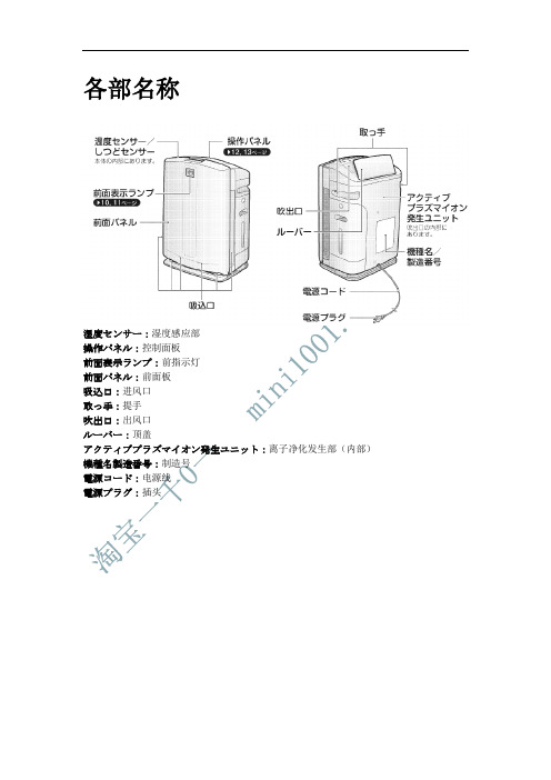
各部名称湿度センサー:湿度感应部操作パネル:控制面板前面表示ランプ:前指示灯前面パネル:前面板吸込口:进风口取っ手:提手吹出口:出风口ルーバー:顶盖アクティブプラズマイオン発生ユニット:离子净化发生部(内部)機種名製造番号:制造号電源コード:电源线電源プラグ:插头前面パネル:前面板プレフィルター:前置滤网脱臭フィルター:除臭滤网集塵フィルター:集尘滤网ユニット1(プラズマイオン化部):滤芯(离子化部)ユニット2(ストリーマユニット):滤芯2(流光净化部)ニオイセンサー:异味感应器ホコリセンサー:灰尘感应器安全ガード:安全网加湿フィルターユニット:加湿滤芯水タンク:水箱加湿トレー:加湿托盘送風ファン:风扇フロート:卡扣(禁止拆卸)銀イオンカートリッジ:银离子感应芯片使用前的准备前面指示灯お知らせランプ:提示灯。
与滤芯1,2和加水指示灯同时亮。
ハウスダスト:灰尘指示灯。
分为绿色,橙色,红色。
正常时为绿色,中等灰尘为橙色,严重为红色。
(开后7秒内一直为绿色,是检测中)ニオイ:异味指示灯。
分为绿色,橙色,红色。
正常为绿色,中等为橙色,严重为红色。
插拔电源和重按前面板后,开机第一分钟内显示为绿色。
水除菌中:加湿工作时会亮。
現在湿度目安(%):现在湿度指示器。
表示范围20%到90%之间。
低于20%时,显示为20。
高于90%时,显示为90%。
控制面板ユニット1洗浄:滤芯1需要清洗时会亮ユニット2洗浄:滤芯2需要清洗时会亮給水:水箱没有水时会亮(没有水时,空气净化机也可以单独使用)会有PPP的提示音2秒押し:长按两秒{表示ランプ(明暗切)}控制面板会锁住,可以仿制小孩误操作表示ランプ(明暗切):指示灯亮度调节键,分别是亮,暗,关闭。
切タイマー:定时关机键,按一下是1小时,两下是两小时,三下是4小时,四下是停止定时关机,相应指示灯会亮。
入タイマー:定时开机键,按一下是4小时后,两下是6小时后,三下是8小时后,四下是停止定时开机,相应指示灯会亮。
空气净化器使用指南

空气净化器使用指南空气净化器是一种有效提高室内空气质量的设备。
使用空气净化器可以帮助净化室内空气中的污染物,保持空气清新和健康。
本文档将介绍如何正确使用空气净化器,并提供一些建议,以确保您充分利用其功能。
步骤一:选择合适的空气净化器在购买空气净化器之前,请考虑以下因素:- 房间尺寸:确保选购的空气净化器适合您的房间大小,以确保其有效性。
- 污染源:如果您的房间内有明显的污染源(如卧室内的宠物、烟草烟雾等),则选择具有对应过滤功能的空气净化器。
步骤二:放置和安装1. 将空气净化器放置在离墙面一定距离的位置,以确保空气的均匀循环。
避免将其放置在堵塞的角落或附近有阻挡物的地方。
2. 接通电源并按照说明书的指引安装空气净化器。
确保净化器处于稳定的位置,并与电源线相连。
步骤三:正确操作1. 在使用空气净化器之前,请仔细阅读说明书,并按照说明进行操作。
2. 打开空气净化器的开关,并选择适当的运行模式,如全天候模式、睡眠模式等,根据需要进行调整。
3. 定期更换滤网以确保空气净化器的有效性。
具体的更换周期和方式,请参考说明书。
步骤四:注意事项1. 使用空气净化器时,请确保房间的门窗关闭,以防止室外空气的污染物进入室内影响空气净化效果。
2. 避免将金属或其他异物接近空气净化器,以防止发生故障或触电。
3. 定期清洁空气净化器的外壳和过滤器,以保持设备的正常运行和净化效果。
空气净化器可以为您的生活环境提供洁净的空气和舒适的居住条件。
通过正确选择、安装和使用空气净化器,并遵循上述注意事项,您可以充分发挥其功能并改善室内空气质量。
请注意,本文档提供了一般性的使用指南,具体的操作步骤和注意事项可能因不同的空气净化器品牌和型号而有所不同。
因此,请在使用前仔细阅读和遵循产品说明书的指引。
Daikin 环保冷气系统产品说明书
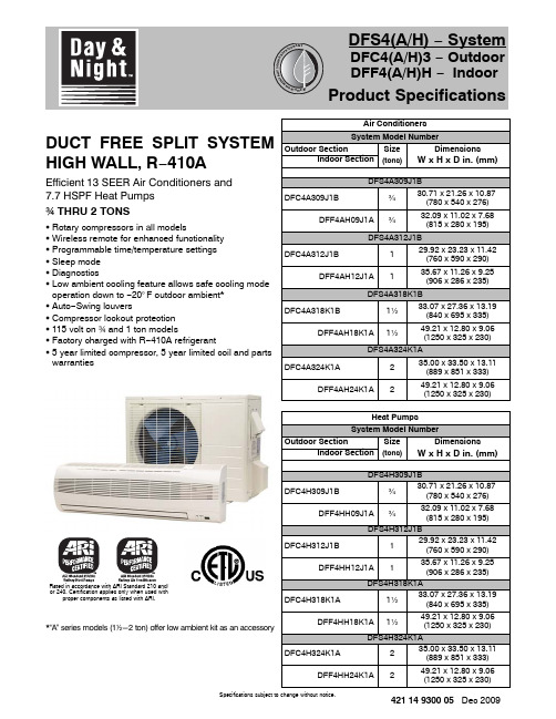
Specifications subject to change without notice.421 14 9300 05 Dec 2009DUCT FREE SPLIT SYSTEM HIGH WALL, R −410AEfficient 13 SEER Air Conditioners and 7.7 HSPF Heat Pumps w THRU 2 TONSS Rotary compressors in all modelsS Wireless remote for enhanced functionality S Programmable time/temperature settings S Sleep mode S DiagnosticsS Low ambient cooling feature allows safe cooling modeoperation down to −20°F outdoor ambient *S Auto −Swing louversS Compressor lockout protection S 115 volt on w and 1 ton modelsS Factory charged with R −410A refrigerantS 5 year limited compressor, 5 year limited coil and parts warrantiesRated in accordance with ARI Standard 210 and/or 240. Certification applies only when used withproper components as listed with ARI.*“A ” series models (12-2 ton) offer low ambient kit as an accessoryAir Conditioners System Model NumberOutdoor Section SizeDimensionsIndoor Section (tons)W x H x D in. (mm)DFS4A309J1BDFC4A309J1B¾30.71 x 21.26 x 10.87(780 x 540 x 276)DFF4AH09J1A¾32.09 x 11.02 x 7.68(815 x 280 x 195)DFS4A312J1BDFC4A312J1B129.92 x 23.23 x 11.42(760 x 590 x 290)DFF4AH12J1A135.67 x 11.26 x 9.25(906 x 286 x 235)DFS4A318K1BDFC4A318K1B1½33.07 x 27.36 x 13.19(840 x 695 x 335)DFF4AH18K1A1½49.21 x 12.80 x 9.06(1250 x 325 x 230)DFS4A324K1ADFC4A324K1A235.00 x 33.50 x 13.11(889 x 851 x 333)DFF4AH24K1A249.21 x 12.80 x 9.06(1250 x 325 x 230)Heat Pumps System Model NumberOutdoor Section SizeDimensionsIndoor Section (tons)W x H x D in. (mm)DFS4H309J1BDFC4H309J1B¾30.71 x 21.26 x 10.87(780 x 540 x 276)DFF4HH09J1A¾32.09 x 11.02 x 7.68(815 x 280 x 195)DFS4H312J1BDFC4H312J1B129.92 x 23.23 x 11.42(760 x 590 x 290)DFF4HH12J1A135.67 x 11.26 x 9.25(906 x 286 x 235)DFS4H318K1ADFC4H318K1A1½33.07 x 27.36 x 13.19(840 x 695 x 335)DFF4HH18K1A1½49.21 x 12.80 x 9.06(1250 x 325 x 230)DFS4H324K1ADFC4H324K1A235.00 x 33.50 x 13.11(889 x 851 x 333)DFF4HH24K1A249.21 x 12.80 x 9.06(1250 x 325 x 230)PRODUCT SPECIFICATIONS Duct Free Split System − High Wall: DFS4(A/H), DFC4(A/H)3, DFF4(A/H)HSpecifications subject to change without notice.2421 14 9300 05Fig. 1 - DFF4(A/H)H/DFC4(A/H)3 09−12Parts List and ClearancesNote :- If the outdoor unit is higher than the indoor unit, prevent rain from flowing into the indoor unit along the connection pipe by making a downward arc in the connection pipe before it enters the wall to the indoor unit. This will ensure that rain will drip from the connection pipe before it enters the wall.- The illustration above is only a sketch. Different models may be slightly different.PRODUCT SPECIFICATIONS Duct Free Split System − High Wall: DFS4(A/H), DFC4(A/H)3, DFF4(A/H)H Specifications subject to change without notice.421 14 9300 053Fig. 2 - DFF4(A/H)H/DFC4(A/H)3 18−24Parts List and ClearancesNote :- If the outdoor unit is higher than the indoor unit, prevent rain from flowing into the indoor unit along the connection pipe by making a downward arc in the connection pipe before it enters the wall to the indoor unit. This will ensure that rain will drip from the connection pipe before it enters the wall.- The illustration above is only a sketch. Different models may be slightly different.PRODUCT SPECIFICATIONS Duct Free Split System − High Wall: DFS4(A/H), DFC4(A/H)3, DFF4(A/H)HSpecifications subject to change without notice.4421 14 9300 05DIMENSIONSINDOOROUTDOORSERVICE VALVE LOCATIONSPRODUCT SPECIFICATIONS Duct Free Split System − High Wall: DFS4(A/H), DFC4(A/H)3, DFF4(A/H)HSpecifications subject to change without notice.421 14 9300 055Outdoor/Indoor Model Size 09J1B 12J1B 18K1B 24K1A PHYSICAL DATA − Air ConditionerCooling Capacity (BTU/hr)9,20011,40017,50022,000SEER13.013.013.013.0Moisture Removal Gallons/hr (Liters/hr).24 (0.9).36 (1.35).41 (1.55).53 (2.0)Indoor Fan CFM (High speed)325425630750Indoor Sound Rating (dBA High − dBA Low)53 − 3958 − 5159 − 5464 − 59Outdoor Sound Rating (dBA)65656867Liquid Line Connection Size (in.)1/41/41/43/8Vapor Line Connection Size (in.)3/81/21/25/8Maximum Vertical Separation (ft.)Indoor Higher than Outdoor 35355060Maximum Vertical Separation (ft.)Indoor Lower than Outdoor 35355060Maximum Line −set Length (ft.)6565100100Factory Charge R −410A (lbs.){2.32.94.15.3{ Models 09, 12, and 18 are factory charged for 25 feet of interconnecting line. For greater line lengths (out to the limits specified in the literature) charge should be added at 0.1 oz. per each additional foot of line added.Net Weight, Outdoor Lbs. (Kg)70.4 (32)79.2 (36)116.6 (53)149.6 (68)Net Weight, Indoor Lbs. (Kg)17.6 (8)25.3 (11.5)39.6 (18)39.6 (18)OUTDOOR ELECTRICAL DATA − Air ConditionerRequired Supply Voltage 115−1−60 AC 208/230−1−60 AC Minimum Circuit Ampacity −MCA (amps)12151114Maximum OverCurrentProtective device − MOCP (amps)20252025Compressor RLA (Rated Load Amps )LRA (Locked Rotor Amps)7.5409.9477.332.69.734.8Fan Motor Amps 0.690.690.780.62INDOOR ELECTRICAL DATA − Air ConditionerRequired Supply Voltage 35 DC208/230−1−60 AC FLA (Full Load Amps)1.1 1.180.260.39PRODUCT SPECIFICATIONS Duct Free Split System − High Wall: DFS4(A/H), DFC4(A/H)3, DFF4(A/H)HSpecifications subject to change without notice.6421 14 9300 05Outdoor/Indoor Model Size 09J1B 12J1B 18K1B 24K1A PHYSICAL DATA − Heat PumpCooling Capacity (BTU/hr)9,60011,50017,50022,000SEER13.013.013.013.0Heating Capacity (BTU/hr)9,40011,50017,00021,400HSPF7.77.77.77.7Moisture Removal Gallons/hr (Liters/hr).24 (0.9).36 (1.35).41 (1.55).53 (2.0)Indoor Fan CFM (High speed)325425630750Indoor Sound Rating (dBA High − dBA Low)52 − 4259 − 5154 − 5855−60Outdoor Sound Rating (dBA)66647267Liquid Line Connection Size (in.)1/41/41/43/8Vapor Line Connection Size (in.)3/81/21/25/8Maximum Vertical Separation (ft.)Indoor Higher than Outdoor 35355060Maximum Vertical Separation (ft.)Indoor Lower than Outdoor 35355060Maximum Line −set Length (ft.)6565100100Factory Charge R −410A (lbs.){2.43.04.55.3{ Models 09 and 12 are factory charged for 25 feet of interconnecting line. For greater line lengths (out to the limits specified in the literature) charge should be added at 0.1 oz. per each additional foot of line added.Net Weight, Outdoor Lbs. (Kg)72.6 (33)83.6 (38)117.7 (53.5)151 (68.5)Net Weight, Indoor Lbs. (Kg)17.6 (8)25.3 (11.5)39.6 (18)39.6 (18)OUTDOOR ELECTRICAL DATA − Heat PumpRequired Supply Voltage 115−1−60 AC 208/230−1−60 AC Minimum Circuit Ampacity −MCA (amps)12151114Maximum OverCurrentProtective device − MOCP (amps)20252025Compressor RLA (Rated Load Amps )LRA (Locked Rotor Amps)7.5409.9477.332.69.734.8Fan Motor Amps 0.690.690.780.62INDOOR ELECTRICAL DATA − Heat PumpRequired Supply Voltage 35 DC208/230−1−60 AC FLA (Full Load Amps)1.1 1.180.260.39PRODUCT SPECIFICATIONS Duct Free Split System − High Wall: DFS4(A/H), DFC4(A/H)3, DFF4(A/H)HSpecifications subject to change without notice.421 14 9300 057ACCESSORIESPart Number Description Used On Model SizeNADA001DK Condensate Pump 9, 12NADA002DK Condensate Pump 18, 24NADA002LA Low Ambient Kit *ALL NADA003CH Crankcase Heater (120V)9, 12NADA004CH Crankcase Heater (240V)18, 241173540Isolation Relay (120V) *9, 121174662Isolation Relay (240V) *18, 24* When Low Ambient Kit is used with Heat Pump, additional Isolation Relay is required.PRODUCT SPECIFICATIONS Duct Free Split System − High Wall: DFS4(A/H), DFC4(A/H)3, DFF4(A/H)HSpecifications subject to change without notice.8421 14 9300 05DUCT FREE SPLIT SYSTEM MODEL NUMBER IDENTIFICATION GUIDE − OUTDOORDFC 4A 309J 1BDFC = Duct Free CondenserDFS = Duct Free System4 = Environmentally Sound R −410A REFRIGERANT A = Air Conditioner H = Heat Pump TYPE3 = 134 = 14NAMEPLATE SEER09 = 9,000 BTUH = ¾ ton 12 = 12,000 BTUH = 1 ton 18 = 18,000 BTUH = 1½ tons 24 = 24,000 BTUH = 2 tons NOMINAL CAPACITYJ = 115−1−60K = 208/230−1−60SUPPLY VOLTAGE1 = Single Zone2 = Dual Zone3 = Tri Zone SALES CODE / FEATURESSales CodeDUCT FREE SPLIT SYSTEM MODEL NUMBER IDENTIFICATION GUIDE − INDOORDFF 4A H 09J 1BDFF = Duct Free Fan CoilDFS = Duct Free System4 = Environmentally Sound R −410A REFRIGERANTA = Air Conditioner H = Heat Pump TYPEH = High Wall U= Under Ceiling C = CassetteAPPLICATION09 = 9,000 BTUH = ¾ ton 12 = 12,000 BTUH = 1 ton 18 = 18,000 BTUH = 1½ tons 24 = 24,000 BTUH = 2 tons NOMINAL CAPACITYJ = 115−1−60K = 208/230−1−60SUPPLY VOLTAGE1 = Single Zone2 = Dual Zone3 = Tri Zone SALES CODE / FEATURESSales CodeInternational Comfort Products, LLC Lewisburg, T ennessee 37091 USA。
