DAIKIN大金 ACK70N 空气净化器 中文说明书
空气净化器使用方法

空气净化器使用方法
空气净化器是一种能够净化室内空气的电器设备,它可以有效去除空气中的灰尘、细菌、病毒、花粉、甲醛等有害物质,提供健康的室内空气环境。
以下是使用空气净化器的步骤:
1. 确定使用需求:根据自身需求选择适合的空气净化器,包括净化器的净化面积、过滤效果和附加功能等。
2. 放置位置:将空气净化器放置在通风良好的位置,远离障碍物,确保净化器能够顺畅吸入空气。
3. 连接电源:将空气净化器插入电源插座,并打开电源开关。
4. 设定模式:根据需要选择合适的净化模式,如自动模式、静音模式或强力模式等。
5. 启动净化:按下启动按钮,让空气净化器开始工作。
一般情况下,净化器会自动监测室内空气质量,并调整净化器的工作强度。
6. 定期更换滤芯:根据空气净化器的使用说明,定期更换滤芯。
滤芯的寿命因不同品牌和型号而异,一般为3-6个月。
7. 定期清洁:定期清洁空气净化器的外壳和进风口,保持净化器的正常工作状态。
8. 注意安全:使用空气净化器时,应注意避免水分进入净化器
内部,避免长时间暴露于阳光直射下。
使用空气净化器能够改善室内空气质量,提高居住环境的舒适度和健康程度。
但需要注意的是,空气净化器并不能完全替代良好的通风和保持清洁的环境,因此仍需注意保持良好的室内通风。
空气净化器用户使用手册
Scqair1苍穹空气净化器用户使用手册P01 目录企业简介 (2)整机及配件 (3)产品部件介绍 (4)快速使用指南 (5)注意事项............................................................ 6-7 操作说明............................................................ 8-9 净化功能.. (10)技术创新 (11)工作原理 (12)技术参数 (13)保养维护 (14)故障排除 (15)使用前操作事项 (16)售后服务 (17)产品合格证 (17)售后服务卡 (18)感谢您使用苍穹空气净化器,使用前请仔细阅读使用手册并妥善保管。
企业介绍P02上海苍穹环保科技有限公司致力于健康型高科技事业,专注空气净化系列产品的研发、生产、安装和销售。
公司的“圆孔通道均场空气净化装置”、“高频高压除尘灭菌装置“等专利技术,“符合国际上高压静电空气净化技术的发展方向”,属国内领先,并达到国际同类技术的先进水平“。
此技术最重要的特点是,能在有人场所连续同步高效除尘、除菌、除放射性氡子体。
此外,这一技术与一种新型的纳米催化剂材料配合使用,能高效去除空气中的甲醛、苯TVOC等有害气体。
静电式空气净化器技术已经列入卫生部《医疗卫生机构消毒规范》。
苍穹空气净化器通过国家疾控中心检测、获得卫生部(消)字号批文。
苍穹空气净化器已在地铁、机场、医院、学校、宾馆、商场、办公大楼、公交车等公共场和食品、药品、化妆品厂等对空气洁净度有苛刻要求的领域,得以成功应用。
苍穹“静电式车用空调配套空气净化装置”是中华人民共和国科技部创新基金支持项目,这项技术产品在2010年世博会专用申沃大巴成功推广。
它能同时除尘杀菌出醛、去除PM2.5,是目前洁净车内空气、保障司乘人员健康呼吸的最为便捷有效的技术。
首创的苍穹“除氡”专利技术,改变了原来的空气净化器不能去除空气中放射性污染认识。
空气净化器产品说明书滤芯更换与空气检测

空气净化器产品说明书滤芯更换与空气检测空气净化器产品说明书一、概述空气净化器是一种用于净化室内空气的设备,通过滤芯的过滤和空气检测功能,有效减少室内空气中的颗粒物、异味和有害气体,提供清新健康的室内环境。
本说明书将详细介绍空气净化器滤芯的更换方法和空气检测功能。
二、滤芯更换1. 滤芯种类空气净化器滤芯主要分为预过滤网、HEPA滤网和活性炭滤芯三种类型。
预过滤网:预过滤网位于空气净化器进风口,主要用于过滤大颗粒的灰尘、粉尘和宠物毛发等。
HEPA滤网:HEPA滤网是核心滤芯,在空气净化器中起到最重要的过滤作用。
它可以有效去除细小至0.3微米的颗粒物,如花粉、粉尘、细菌、病毒等。
活性炭滤芯:活性炭滤芯主要用于吸附异味和有害气体,如甲醛、苯等。
2. 滤芯更换步骤(1)断电:在更换滤芯前,请确保空气净化器已断电,并拔掉电源插头。
(2)打开滤芯仓:根据所使用的空气净化器型号,找到滤芯仓的位置,并打开滤芯仓盖。
(3)取出旧滤芯:将旧滤芯从滤芯仓中取出,并丢弃。
(4)安装新滤芯:将新滤芯按照箭头指示的方向放入滤芯仓中,保证滤芯与仓壁完全贴合。
(5)关闭滤芯仓:将滤芯仓盖盖紧,并确保没有松动。
(6)接通电源:将电源插头插入插座,并接通电源。
(7)复位滤芯指示灯:根据具体型号,找到滤芯指示灯并按下复位按钮,使指示灯恢复正常状态。
三、空气检测功能空气净化器通常配备了空气检测功能,可以实时监测室内空气质量,并提供相应的指示。
1. 空气质量指示灯空气净化器上有一个空气质量指示灯,通常分为红、黄和绿三个档位,分别代表差、一般和好的室内空气质量。
指示灯会根据空气检测结果自动调整颜色,提醒用户当前空气质量状况。
2. PM2.5检测部分空气净化器配备了PM2.5检测功能,可以实时监测室内空气中PM2.5颗粒物的浓度,并通过显示屏上的数字或指示灯显示结果。
用户可以根据检测结果,调整净化器的工作模式,以达到更好的空气净化效果。
3. 智能模式智能模式是一种根据空气质量自动调整净化器工作模式的功能。
空气净化器使用指南

空气净化器使用指南随着城市化的加速,人们的生活方式也发生着巨大的变化,而人工劣化的环境也直接影响了人们的生活质量。
我们的身体对环境中的污染会产生很大的影响,尤其是室内空气质量的问题更加复杂。
因此,如今的市场上出现了很多种各异的空气净化器用来解决这一问题。
然而,对于一些可能没有了解清晰的人来说,怎样选择和使用一款空气净化器是不易的。
那么,这里提供一份空气净化器使用指南,以帮助你更好地选择和使用一款符合你需求的空气净化器。
1. 如何选择一款适合自己的空气净化器?首先,当你购买一个空气净化器时,要确定你所要处理的房间大小,这将决定你需要何种尺寸的净化器。
其次,查看一下净化器的CADR评级,该评级代表着净化器处理空气的效率。
如果你有任何宠物或是有过敏史,我们建议选择一个带有真正的HEPA滤网的空气净化器,它可以有效地过滤出一些较小的空气污染颗粒。
此外,综合考虑过滤器的独特功能、滤网的使用寿命以及在空气中能够净化的种类,可以帮助你选择出适合自己的净化器。
2. 如何正确地使用空气净化器?不同机型空气净化器具有不同的操作方式和设置,因此,请仔细阅读所购买空气净化器的使用说明书。
净化器必须放置在一个适当的位置,通常是那些可以有效扩散净化空气的地方,例如客厅或是卧房的中央位置。
净化器可以扩散的区域所依据空气净化器的尺寸和功率而定。
3. 如何维护空气净化器以使其保持最高状态?不同类型的空气净化器带有不同的滤网,要定期更换滤网,以保证净化器的高效过滤,并且总的更换频率取决于使用的频率和环境。
可以适当地定时清洗除尘器,通常每周至少清理一次,有助于保持净化器的正常运转。
还要保持净化器和周围环境的干净,这有助于确保其过滤空气的干净和功效。
4. 使用空气净化器有什么影响?使用空气净化器可以提高室内空气质量,减少对人体的危害,这对有敏感性群体,如婴儿、孕妇以及一些疾病高发人群让直接受益。
使用空气净化器还可以控制室内空气湿度,缓解一些病痛和呼吸问题的出现。
大金中央空调控制器使用说明书
大金中央空调线控器使用说明书公司工程部制作年月日1.开/关钮:按下按钮,则系统开始运转,再按一次按钮,则系统停止运转。
2.运转指示灯(红色):在运转时,该指示灯点亮。
3.“”显示在控制下转换:当该显示出现时,不能使用控制器进行制冷、制热、、除湿运转的转换。
4.“”显示摆动挡板:可进行固定风向和自动摆动设定;可通过21键来进行调节。
5.“”显示(设定温度):可通过17键来调节温度。
6.“”“”“”“”显示(运转方式):该显示表示现在运转的方式;可通过20键来调节。
7.“”显示(程序设定的时间):该显示表示程序的系统开始运转和停止运转的时间。
8.“”显示(检验/试运转):当按下检验/试运转按钮时,该显示表示系统现在的运转方式。
9.“”显示(处于集中控制之下):当该显示出现时,表示系统处于集中控制之下(本显示不是标准规格)。
10.“”显示(送风速度):该显示表示风扇的速度,“低”或“高”。
11.“”显示(空气滤尘网清扫时期):请参照室内机附带的使用说明书。
12.“”显示(除霜/热起动):⑴除霜运转随着室外机盘管上凝结的冰霜增多,制热效果将降低,系统将自动进入除霜运转;室内机风扇停止运转,控制器上显示“”(除霜/热起动);除霜运转6至8分钟(最长10分钟)以后,系统将回到制热运转。
⑵热起动为了防止在制热开始运转时,从室内机吹出冷风,室内机的风扇自动停止运转。
控制器上显示“”(除霜/热起动)。
13.定时器方式启动/停止钮:由专业人员操作。
14.定时器开/关钮:由专业人员操作。
15.检验/运转钮:本按钮仅可由专业的维修人员进行维修时使用!正常运转时请勿使用!16.程序设定时间钮:使用该钮,可设定程序“启动或停止”系统运转的时间。
17.温度设定钮:使用该钮,可设定温度调节器的设定温度。
18.空气滤尘网清扫指示复位钮:请参照室内机附带的使用说明书。
19.风扇速度控制钮:按该钮,可根据您的要求选择风扇的速度,“低”或“高”。
空气净化器说明书.pdf_1701989189.964476

2
max mark.
max
1
3. Close the lid of the dispenser for rinse aid. a The lid clicks into position.
Adding detergent
1. Add the detergent to the dry detergent dispenser.
Programme
1) Duration [h:min] 2) Energy [kWh] 3) Water [l]
Intensive 70°
1) 2:05 - 2:15 2) 1,300 - 1,400 3) 11,5 - 14,0
Auto 45-65°
1) 1:40 - 2:45 2) 0,900 - 1,500 3) 7,0 - 15,5
50 ml
2. Close the lid of the deter-
25 ml
gent dispenser.
15 ml
a The lid clicks into position.
Programmes
The programme data has been measured in the laboratory according to European standard EN 60436. The consumption figures depend on the programme and additional function selected. The runtime will change if the rinse aid system is switched off or rinse aid needs to be added.
室内空气净化器的使用说明
室内空气净化器的使用说明室内空气净化器使用说明为了保障家庭成员的健康和舒适,室内空气净化器成为现代家庭必备的电器。
它可以有效去除室内空气中的异味、细菌和有害物质,提供一个清新、健康的室内环境。
但室内空气净化器的使用也需注意一些细节,下面,我们将详述使用说明。
1. 选购合适的空气净化器。
首先,根据室内面积选择合适的空气净化器。
一般来说,小型空气净化器适用于小型卧室或办公室,而大型空气净化器适用于客厅或大面积空间。
其次,需要根据需要选择不同类型的净化器,如活性炭过滤器、HEPA过滤器或光触媒过滤器等,以满足不同的净化需求。
最后,确保选购的空气净化器符合国家相关标准,具备合格的净化效果和可靠的品质。
2. 安装净化器。
在安装空气净化器之前,需要将净化器放置于远离阳光直射和异味源的地方。
保持周围空间畅通,不要堵塞空气进出口。
同时,确保电源线路的接地良好,以确保电器的正常运行和安全使用。
3. 清洁和更换滤芯。
空气净化器的滤芯需要定期清洁和更换。
根据使用频率和环境,一般建议每3-6个月更换一次滤芯。
在更换滤芯之前,务必关闭电源,然后按照说明书的指导清洁或更换滤芯。
清洁滤芯时,可以用软毛刷轻轻刷洗,或者用适量清洁液清洗,然后晾干。
更换滤芯时,注意选择适合的滤芯规格,确保净化器的正常运行。
4. 正确使用空气净化器。
在使用空气净化器时,为了保证净化效果,可以根据环境需要选择合适的净化模式。
一般为了达到最佳净化效果,可以选择自动模式或者静音模式。
同时,需要定期清洁空气净化器的外壳和面板,以保持设备的整洁和正常运行。
5. 定期检测空气质量。
空气净化器需要定期检测室内空气质量,以确定净化器的净化效果和滤芯的更换时机。
可以使用空气质量检测仪器进行测量,或者根据净化器的显示器显示的空气质量状况进行判断。
如果发现净化效果下降,或者显示器显示空气质量较差,应及时清洁或更换滤芯。
总结:室内空气净化器的使用对于保障家庭成员的健康和舒适环境非常重要。
大金ACK70N操作说明书

各部名称湿度センサー:湿度感应部操作パネル:控制面板前面表示ランプ:前指示灯前面パネル:前面板吸込口:进风口取っ手:提手吹出口:出风口ルーバー:顶盖アクティブプラズマイオン発生ユニット:离子净化发生部(内部)機種名製造番号:制造号電源コード:电源线電源プラグ:插头前面パネル:前面板プレフィルター:前置滤网脱臭フィルター:除臭滤网集塵フィルター:集尘滤网ユニット1(プラズマイオン化部):滤芯(离子化部)ユニット2(ストリーマユニット):滤芯2(流光净化部)ニオイセンサー:异味感应器ホコリセンサー:灰尘感应器安全ガード:安全网加湿フィルターユニット:加湿滤芯水タンク:水箱加湿トレー:加湿托盘送風ファン:风扇フロート:卡扣(禁止拆卸)銀イオンカートリッジ:银离子感应芯片使用前的准备前面指示灯お知らせランプ:提示灯。
与滤芯1,2和加水指示灯同时亮。
ハウスダスト:灰尘指示灯。
分为绿色,橙色,红色。
正常时为绿色,中等灰尘为橙色,严重为红色。
(开后7秒内一直为绿色,是检测中)ニオイ:异味指示灯。
分为绿色,橙色,红色。
正常为绿色,中等为橙色,严重为红色。
插拔电源和重按前面板后,开机第一分钟内显示为绿色。
水除菌中:加湿工作时会亮。
現在湿度目安(%):现在湿度指示器。
表示范围20%到90%之间。
低于20%时,显示为20。
高于90%时,显示为90%。
控制面板ユニット1洗浄:滤芯1需要清洗时会亮ユニット2洗浄:滤芯2需要清洗时会亮給水:水箱没有水时会亮(没有水时,空气净化机也可以单独使用)会有PPP的提示音2秒押し:长按两秒{表示ランプ(明暗切)}控制面板会锁住,可以仿制小孩误操作表示ランプ(明暗切):指示灯亮度调节键,分别是亮,暗,关闭。
切タイマー:定时关机键,按一下是1小时,两下是两小时,三下是4小时,四下是停止定时关机,相应指示灯会亮。
入タイマー:定时开机键,按一下是4小时后,两下是6小时后,三下是8小时后,四下是停止定时开机,相应指示灯会亮。
(整理)大金空气净化器docx.

售后服务:全国联保
(2)环境的非使用价值。环境的非使用价值(NUV)又称内在价值,相当于生态学家所认为的某种物品的内在属性,它与人们是否使用它没有关系。适用对象:家用
适用面积:41m^2 (含)-60m^2 (含)
(二)安全评价的基本原则外观尺寸:576*395*230/576*403*24(含突起处)
(2)列出有关的法律、法规、规章、标准、规范和评价对象被批准设立的相关文件及其他有关参考资料等安全预评价的依据。功能:除甲醛、除烟除尘、杀菌
(1)资质等级。评价机构的环评资பைடு நூலகம்分为甲、乙两个等级。环评证书在全国范围内使用,有效期为4年。工作原理:活性炭,等离子,HEPA技术,光触媒等
同建设项目安全评价相关但又有不同的还有:《地质灾害防治管理办法》规定的地质灾害危险性评估,《地震安全性评价管理条例》中规定的地震安全性评价,《中华人民共和国职业病防治法》中规定的职业病危害预评价等。大金空气净化器 家用除甲醛MC70KMV2-N
3)选择价值。选择价值(OV)又称期权价值。我们在利用环境资源的时候,并不希望它的功能很快消耗殆尽,也许会设想未来该资源的使用价值会更大。产品名称:Daikin/大金MC70KMV2-N
品牌:Daikin/大金
环境,是指影响人类生存和发展的各种天然的和经过人工改造的自然因素的总体。型号:MC70KMV2-N
噪音:31-60dB
控制方式:遥控式
规划编制单位应当在报送审查的环境影响报告书中附具对公众意见采纳与不采纳情况及其理由的说明。滤网类型:复合滤网
4.广泛参与原则。颜色:香槟金
三、规划环境影响评价风量:420立方米/小时
空气净化器使用指南

空气净化器使用指南空气污染已经成为全球关注的焦点,空气净化器作为一种有效的治理手段,越来越受人们的青睐。
但是,购买了空气净化器并不代表空气质量就变得优良了。
使用时一些小技巧也至关重要。
本篇文章将为您介绍空气净化器的使用指南。
1. 了解你的空气净化器空气净化器有多种型号,不同的型号使用方法和功能各有不同。
在购买空气净化器后,首先应当了解清楚自己的空气净化器是什么型号的、有哪些功能、如何使用以及如何维护。
空气净化器的功能通常有净化空气、除湿、杀菌除臭、添加湿气等。
在使用空气净化器时,应该根据自己的实际需求选择适合自己的功能,以达到最优的使用效果。
2. 空气净化器的放置位置很重要一般来说,空气净化器应该放置在离人体距离较近的地方。
这样能够保证空气净化器的净化效果最大化,更多的废气被过滤掉,人体受到的污染才会降低。
同时,在放置空气净化器时要注意不要阻碍空气流通。
放置空气净化器的最佳位置是房间中央,这样才能达到更好的气流效果。
3. 关注空气净化器的过滤系统空气净化器使用的过滤系统非常重要,因为它决定了空气净化器能否彻底过滤掉空气中的废气。
根据过滤系统的不同,空气净化器可以分为四种类型:含筛网、带静电吸附板、使用高效过滤器和带有紫外线杀菌功能的空气净化器。
具体的选择应该根据实际需求而定。
在使用空气净化器时,应经常检查过滤器的清洁程度,如果已经过于脏污或饱和,则需要更换。
同时,还应注意定期清洗过滤器以确保过滤效果。
4. 合理使用空气净化器空气净化器的使用应该根据实际情况,选择适当的时间和工作模式。
一般来说,在室内有人的情况下,可以选择低档或中档的工作模式。
当室内人数较少或者没有人时,可以选择关闭空气净化器以节省能源。
此外,使用空气净化器时还应该注意清洁空气净化器周围的环境,避免影响空气净化器的净化效果。
5. 定期维护你的空气净化器定期维护空气净化器可以保证其长期运作和净化效果。
一般来说,需要定期更换空气净化器的过滤器、清洁空气净化器周围的空气、定期检查和更换损坏的配件等。
Daikin 环保冷气系统产品说明书
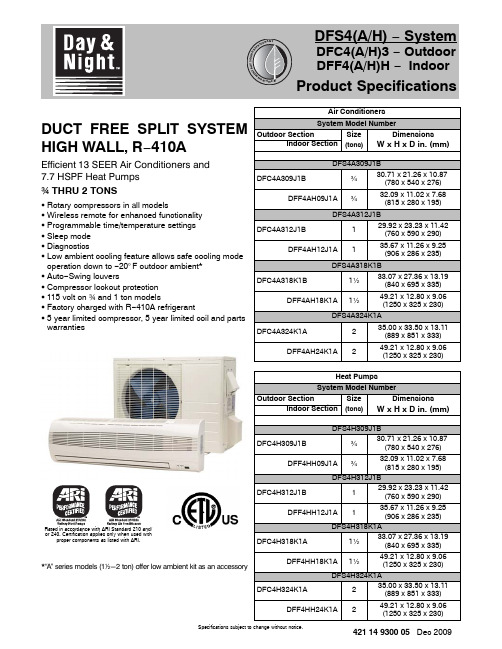
Specifications subject to change without notice.421 14 9300 05 Dec 2009DUCT FREE SPLIT SYSTEM HIGH WALL, R −410AEfficient 13 SEER Air Conditioners and 7.7 HSPF Heat Pumps w THRU 2 TONSS Rotary compressors in all modelsS Wireless remote for enhanced functionality S Programmable time/temperature settings S Sleep mode S DiagnosticsS Low ambient cooling feature allows safe cooling modeoperation down to −20°F outdoor ambient *S Auto −Swing louversS Compressor lockout protection S 115 volt on w and 1 ton modelsS Factory charged with R −410A refrigerantS 5 year limited compressor, 5 year limited coil and parts warrantiesRated in accordance with ARI Standard 210 and/or 240. Certification applies only when used withproper components as listed with ARI.*“A ” series models (12-2 ton) offer low ambient kit as an accessoryAir Conditioners System Model NumberOutdoor Section SizeDimensionsIndoor Section (tons)W x H x D in. (mm)DFS4A309J1BDFC4A309J1B¾30.71 x 21.26 x 10.87(780 x 540 x 276)DFF4AH09J1A¾32.09 x 11.02 x 7.68(815 x 280 x 195)DFS4A312J1BDFC4A312J1B129.92 x 23.23 x 11.42(760 x 590 x 290)DFF4AH12J1A135.67 x 11.26 x 9.25(906 x 286 x 235)DFS4A318K1BDFC4A318K1B1½33.07 x 27.36 x 13.19(840 x 695 x 335)DFF4AH18K1A1½49.21 x 12.80 x 9.06(1250 x 325 x 230)DFS4A324K1ADFC4A324K1A235.00 x 33.50 x 13.11(889 x 851 x 333)DFF4AH24K1A249.21 x 12.80 x 9.06(1250 x 325 x 230)Heat Pumps System Model NumberOutdoor Section SizeDimensionsIndoor Section (tons)W x H x D in. (mm)DFS4H309J1BDFC4H309J1B¾30.71 x 21.26 x 10.87(780 x 540 x 276)DFF4HH09J1A¾32.09 x 11.02 x 7.68(815 x 280 x 195)DFS4H312J1BDFC4H312J1B129.92 x 23.23 x 11.42(760 x 590 x 290)DFF4HH12J1A135.67 x 11.26 x 9.25(906 x 286 x 235)DFS4H318K1ADFC4H318K1A1½33.07 x 27.36 x 13.19(840 x 695 x 335)DFF4HH18K1A1½49.21 x 12.80 x 9.06(1250 x 325 x 230)DFS4H324K1ADFC4H324K1A235.00 x 33.50 x 13.11(889 x 851 x 333)DFF4HH24K1A249.21 x 12.80 x 9.06(1250 x 325 x 230)PRODUCT SPECIFICATIONS Duct Free Split System − High Wall: DFS4(A/H), DFC4(A/H)3, DFF4(A/H)HSpecifications subject to change without notice.2421 14 9300 05Fig. 1 - DFF4(A/H)H/DFC4(A/H)3 09−12Parts List and ClearancesNote :- If the outdoor unit is higher than the indoor unit, prevent rain from flowing into the indoor unit along the connection pipe by making a downward arc in the connection pipe before it enters the wall to the indoor unit. This will ensure that rain will drip from the connection pipe before it enters the wall.- The illustration above is only a sketch. Different models may be slightly different.PRODUCT SPECIFICATIONS Duct Free Split System − High Wall: DFS4(A/H), DFC4(A/H)3, DFF4(A/H)H Specifications subject to change without notice.421 14 9300 053Fig. 2 - DFF4(A/H)H/DFC4(A/H)3 18−24Parts List and ClearancesNote :- If the outdoor unit is higher than the indoor unit, prevent rain from flowing into the indoor unit along the connection pipe by making a downward arc in the connection pipe before it enters the wall to the indoor unit. This will ensure that rain will drip from the connection pipe before it enters the wall.- The illustration above is only a sketch. Different models may be slightly different.PRODUCT SPECIFICATIONS Duct Free Split System − High Wall: DFS4(A/H), DFC4(A/H)3, DFF4(A/H)HSpecifications subject to change without notice.4421 14 9300 05DIMENSIONSINDOOROUTDOORSERVICE VALVE LOCATIONSPRODUCT SPECIFICATIONS Duct Free Split System − High Wall: DFS4(A/H), DFC4(A/H)3, DFF4(A/H)HSpecifications subject to change without notice.421 14 9300 055Outdoor/Indoor Model Size 09J1B 12J1B 18K1B 24K1A PHYSICAL DATA − Air ConditionerCooling Capacity (BTU/hr)9,20011,40017,50022,000SEER13.013.013.013.0Moisture Removal Gallons/hr (Liters/hr).24 (0.9).36 (1.35).41 (1.55).53 (2.0)Indoor Fan CFM (High speed)325425630750Indoor Sound Rating (dBA High − dBA Low)53 − 3958 − 5159 − 5464 − 59Outdoor Sound Rating (dBA)65656867Liquid Line Connection Size (in.)1/41/41/43/8Vapor Line Connection Size (in.)3/81/21/25/8Maximum Vertical Separation (ft.)Indoor Higher than Outdoor 35355060Maximum Vertical Separation (ft.)Indoor Lower than Outdoor 35355060Maximum Line −set Length (ft.)6565100100Factory Charge R −410A (lbs.){2.32.94.15.3{ Models 09, 12, and 18 are factory charged for 25 feet of interconnecting line. For greater line lengths (out to the limits specified in the literature) charge should be added at 0.1 oz. per each additional foot of line added.Net Weight, Outdoor Lbs. (Kg)70.4 (32)79.2 (36)116.6 (53)149.6 (68)Net Weight, Indoor Lbs. (Kg)17.6 (8)25.3 (11.5)39.6 (18)39.6 (18)OUTDOOR ELECTRICAL DATA − Air ConditionerRequired Supply Voltage 115−1−60 AC 208/230−1−60 AC Minimum Circuit Ampacity −MCA (amps)12151114Maximum OverCurrentProtective device − MOCP (amps)20252025Compressor RLA (Rated Load Amps )LRA (Locked Rotor Amps)7.5409.9477.332.69.734.8Fan Motor Amps 0.690.690.780.62INDOOR ELECTRICAL DATA − Air ConditionerRequired Supply Voltage 35 DC208/230−1−60 AC FLA (Full Load Amps)1.1 1.180.260.39PRODUCT SPECIFICATIONS Duct Free Split System − High Wall: DFS4(A/H), DFC4(A/H)3, DFF4(A/H)HSpecifications subject to change without notice.6421 14 9300 05Outdoor/Indoor Model Size 09J1B 12J1B 18K1B 24K1A PHYSICAL DATA − Heat PumpCooling Capacity (BTU/hr)9,60011,50017,50022,000SEER13.013.013.013.0Heating Capacity (BTU/hr)9,40011,50017,00021,400HSPF7.77.77.77.7Moisture Removal Gallons/hr (Liters/hr).24 (0.9).36 (1.35).41 (1.55).53 (2.0)Indoor Fan CFM (High speed)325425630750Indoor Sound Rating (dBA High − dBA Low)52 − 4259 − 5154 − 5855−60Outdoor Sound Rating (dBA)66647267Liquid Line Connection Size (in.)1/41/41/43/8Vapor Line Connection Size (in.)3/81/21/25/8Maximum Vertical Separation (ft.)Indoor Higher than Outdoor 35355060Maximum Vertical Separation (ft.)Indoor Lower than Outdoor 35355060Maximum Line −set Length (ft.)6565100100Factory Charge R −410A (lbs.){2.43.04.55.3{ Models 09 and 12 are factory charged for 25 feet of interconnecting line. For greater line lengths (out to the limits specified in the literature) charge should be added at 0.1 oz. per each additional foot of line added.Net Weight, Outdoor Lbs. (Kg)72.6 (33)83.6 (38)117.7 (53.5)151 (68.5)Net Weight, Indoor Lbs. (Kg)17.6 (8)25.3 (11.5)39.6 (18)39.6 (18)OUTDOOR ELECTRICAL DATA − Heat PumpRequired Supply Voltage 115−1−60 AC 208/230−1−60 AC Minimum Circuit Ampacity −MCA (amps)12151114Maximum OverCurrentProtective device − MOCP (amps)20252025Compressor RLA (Rated Load Amps )LRA (Locked Rotor Amps)7.5409.9477.332.69.734.8Fan Motor Amps 0.690.690.780.62INDOOR ELECTRICAL DATA − Heat PumpRequired Supply Voltage 35 DC208/230−1−60 AC FLA (Full Load Amps)1.1 1.180.260.39PRODUCT SPECIFICATIONS Duct Free Split System − High Wall: DFS4(A/H), DFC4(A/H)3, DFF4(A/H)HSpecifications subject to change without notice.421 14 9300 057ACCESSORIESPart Number Description Used On Model SizeNADA001DK Condensate Pump 9, 12NADA002DK Condensate Pump 18, 24NADA002LA Low Ambient Kit *ALL NADA003CH Crankcase Heater (120V)9, 12NADA004CH Crankcase Heater (240V)18, 241173540Isolation Relay (120V) *9, 121174662Isolation Relay (240V) *18, 24* When Low Ambient Kit is used with Heat Pump, additional Isolation Relay is required.PRODUCT SPECIFICATIONS Duct Free Split System − High Wall: DFS4(A/H), DFC4(A/H)3, DFF4(A/H)HSpecifications subject to change without notice.8421 14 9300 05DUCT FREE SPLIT SYSTEM MODEL NUMBER IDENTIFICATION GUIDE − OUTDOORDFC 4A 309J 1BDFC = Duct Free CondenserDFS = Duct Free System4 = Environmentally Sound R −410A REFRIGERANT A = Air Conditioner H = Heat Pump TYPE3 = 134 = 14NAMEPLATE SEER09 = 9,000 BTUH = ¾ ton 12 = 12,000 BTUH = 1 ton 18 = 18,000 BTUH = 1½ tons 24 = 24,000 BTUH = 2 tons NOMINAL CAPACITYJ = 115−1−60K = 208/230−1−60SUPPLY VOLTAGE1 = Single Zone2 = Dual Zone3 = Tri Zone SALES CODE / FEATURESSales CodeDUCT FREE SPLIT SYSTEM MODEL NUMBER IDENTIFICATION GUIDE − INDOORDFF 4A H 09J 1BDFF = Duct Free Fan CoilDFS = Duct Free System4 = Environmentally Sound R −410A REFRIGERANTA = Air Conditioner H = Heat Pump TYPEH = High Wall U= Under Ceiling C = CassetteAPPLICATION09 = 9,000 BTUH = ¾ ton 12 = 12,000 BTUH = 1 ton 18 = 18,000 BTUH = 1½ tons 24 = 24,000 BTUH = 2 tons NOMINAL CAPACITYJ = 115−1−60K = 208/230−1−60SUPPLY VOLTAGE1 = Single Zone2 = Dual Zone3 = Tri Zone SALES CODE / FEATURESSales CodeInternational Comfort Products, LLC Lewisburg, T ennessee 37091 USA。
Daikin 环保氧氮系列空调产品说明书
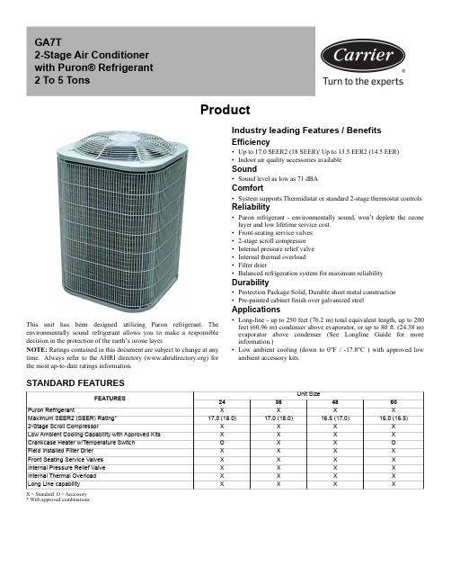
ProductThis unit has been designed utilizing Puron refrigerant. The environmentally sound refrigerant allows you to make a responsible decision in the protection of the earth’s ozone layer.NOTE: Ratings contained in this document are subject to change at any time. Always refer to the AHRI directory () for the most up-to-date ratings information.Industry leading Features / BenefitsEfficiency •Up to 17.0 SEER2 (18 SEER)/ Up to 13.5 EER2 (14.5 EER)•Indoor air quality accessories available Sound•Sound level as low as 71 dBAComfort•System supports Thermidistat or standard 2-stage thermostat controlsReliability•Puron refrigerant - environmentally sound, won’t deplete the ozone layer and low lifetime service cost.•Front-seating service valves •2-stage scroll compressor •Internal pressure relief valve •Internal thermal overload •Filter drier•Balanced refrigeration system for maximum reliabilityDurability•Protection Package:Solid, Durable sheet metal construction •Pre-painted cabinet finish over galvanized steelApplications•Long-line - up to 250 feet (76.2 m) total equivalent length, up to 200feet (60.96 m) condenser above evaporator, or up to 80 ft. (24.38 m)evaporator above condenser (See Longline Guide for more information.)•Low ambient cooling (down to 0°F / -17.8°C ) with approved low ambient accessory kits.X = Standard O = Accessory * With approved combinationsGA7T2-Stage Air Conditioner with Puron® Refrigerant 2 To 5 TonsSTANDARD FEATURESFEATURESUnit Size24364860Puron RefrigerantXXXXMaximum SEER2 (SEER) Rating*17.0 (18.0)17.0 (18.0)16.5 (17.0)16.0 (16.5)2-Stage Scroll CompressorX X X X Low Ambient Cooling Capability with Approved Kits X X X X Crankcase Heater w/Temperature Switch O X X O Field Installed Filter Drier X X X X Front Seating Service Valves X X X X Internal Pressure Relief Valve X X X X Internal Thermal Overload X X X X Long Line capabilityXXXXAHRI RATINGSFor AHRI ratings certificates, please refer to the AHRI directory Additional ratings and system combinations can be accessed via the Ratings Database here: MODEL NUMBER NOMENCLATURE12345678, 9101112G A 7T A N 42400W BrandingOD TypeSEER2OD Design TypeMajor SeriesVoltageRefrigerantNominal Capacity FeatureSpecial FeatureRegion G = Generic A = AC7 = 17 SEER2T =2-Stage A-Z = Major Iteration N = 208-230-1or 208/230-1P = 208-230-3or 208/230-3E = 460-34 = R410A24 = 24,000 BTUH (2 Tons)36 = 36,000 BTUH (3 Tons)48 = 48,000 BTUH (4 Tons)60 = 50,000 BTUH (5 Tons)0 = Standard 0 =StandardW = Standard SouthwestACCATALOG ORDERING NUMBERSSize Model Ordering Number24GA7TAN42400W 36GA7TAN43600W 48GA7TAN44800W 60GA7TAN46000WPHYSICAL DATAUNIT SIZE24364860Compressor Type Scroll REFRIGERANT PuronControlTXV (Puron® Hard Shutoff) Charge lb (kg) 6.03 (2.74)10.3 (4.67)12.22 (5.54)9.27 (4.20)COND FAN Propeller Type, Direct DriveAir Discharge VerticalAir Qty (CFM)2640283047794779 Motor HP 1/121/121/41/4 Motor RPM 800800800800COND COILFace Area (Sq ft)19.320.125.125.1 Fins per In.25202020 Rows 1222 Circuits5877VALVE CONNECT. (In. ID) Vapor 3/47/87/87/8Liquid3/8"REFRIGERANT TUBES* (In. OD) Rated Vapor(0-80 Ft Tube Length)3/47/81 1/81 1/8Liquid (0-80 Ft Tube Length)3/8"REFRIGERANT PIPING LENGTH LIMITATIONSLiquid Line Sizing and Maximum Total Equivalent Lengths† for Cooling Only Systems with R-410APuron® Refrigerant:The maximum allowable length of a residential split system depends on the liquid line diameter and vertical separation between indoor and outdoor units.See Table below for liquid line sizing and maximum lengths :Table 1 – Maximum Total Equivalent LengthOutdoor Unit BELOW Indoor Unit* Maximum actual length not to exceed 200 ft (61 m)†Total equivalent length accounts for losses due to elbows or fitting. See the Long Line Guideline for details. -- = outside acceptable range* Maximum actual length not to exceed 200 ft (61 m)†Total equivalent length accounts for losses due to elbows or fitting. See the Long Line Guideline for details.Units are factory charged for 15 ft (4.6 m) of 3/8” liquid line. The factory charge for 3/8” lineset 9 oz.(266.16 g). When using other length or diameter liquid lines, charge adjustments are required per the chart above.Charging Formula:[(Lineset oz/ft x total length) – (factory charge for lineset)] = charge adjustmentExample 1: System has 15 ft of line set using existing 1/4“ liquid line. What charge adjustment is required? Formula:(.27 oz/ft x 15ft) – (9 oz) = (-4.95) oz.Net result is to remove 4.95 oz of refrigerant from the systemExample 2: System has 45 ft of existing 5/16” liquid line. What is the charge adjustment?Formula:(.40 oz/ft. x 45ft) – (9 oz.) = 9 oz.Net result is to add 9 oz of refrigerant to the systemNOTE: Conditions must be favorable for charging by subcooling method. Indoor temperature must be 70°F to 80°F (21.1°C to 26.7°C), and outdoor temperature must be 70°F to 100°F (21.1°C to 37.8°C). If outside these conditions, adjust charge for long line sets by weigh-in method.SizeLiquid Line ConnectionLiquid Line Diam.w/TXV AC with Puron Refrigerant Maximum Total Equivalent Length†: Outdoor unit BELOW IndoorVertical Separation ft (m)0-5(0-1.5)6-10(1.8-3.0)11-20(3.4-6.1)21-30(6.4-9.1)31-40(9.4-12.2)41-50(12.5-15.2) 51-60(15.5-18.3)61-70(18.6-21.3)71-80(21.6-24.4)24 3/81/4 7575755050--------5/16250*250*250*250*250*225*1751251003/8250*250*250*250*250*250*250*250*250*36 3/85/1617515015010010010075----3//8250*250*250*250*250*250*250*250*250*483/83/8250*250*250*250*250*250*230160--603/83/8250*250*250*225*190150110----Table 2 – Maximum Total Equivalent LengthOutdoor Unit ABOVE Indoor UnitSizeLiquid LineConnectionLiquid LineDiam.w/TXVAC with Puron Refrigerant Maximum Total Equivalent Length †:Outdoor unit ABOVE Indoor Vertical Separation ft (m)25(7.6)26-50(7.9-15.2)51-75(15.5-22.9)76-100(23.2-30.5)101-125(30.8-38.1)126-150(38.4-45.7)151-175(46.0-53.3)176-200(53.6-61.0)243/81/4100125175200225*250*250*250*5/16250*250*250*250*250*250*250*250*3/8250*250*250*250*250*250*250*250*363/85/16225*250*250*250*250*250*250*250*3/8250*250*250*250*250*250*250*250*483/83/8250*250*250*250*250*250*250*250*603/83/8250*250*250*250*250*250*250*250*Table 3 – Refrigerant Charge AdjustmentsLiquid Line SizePuron Charge oz/ft (g/m)3/80.60 (17.74)(Factory charge for lineset = 9 oz / 266.16 g)5/160.40 (11.83)1/40.27 (7.98)LONG LINE APPLICATIONSAn application is considered Long Line, when the refrigerant level in the system requires the use of accessories to maintain acceptable refrigerant management for systems reliability. See Accessory Usage Guideline table for required accessories. Defining a system as long line depends on the liquid line diameter, actual length of the tubing, and vertical separation between the indoor and outdoor units. For Air Conditioner systems, the chart below shows when an application is considered Long Line.NOTE: See Residential Piping and Long Line Guideline for detailsVAPOR LINE SIZING AND COOLING CAPACITY LOSSAcceptable vapor line diameters provide adequate oil return to the compressor while avoiding excessive capacity loss. The suction line diameters shown in the chart below are acceptable for AC systems with Puron refrigerant:* Units are rated with 25 ft (7.6 m) of lineset length. See Vapor Line Sizing and Cooling Capacity Loss table when using other sizes and lengths of lineset.Table 4 – AC with Puron Refrigerant Long Line Description ft (m) Beyond these lengths, a TXV is requiredTotal LengthOutdoor Unit Above or Below Indoor UnitTXV required beyond 50 ft. (15.2 m)TXV required beyond 20 ft. (6.1 m)Table 5 – AC with Puron Refrigerant Long Line Description ft (m) (Beyond these lengths, long line accessories are required)Liquid Line Size Units On Same LevelOutdoor Below Indoor Outdoor Above Indoor1/4 + TXV No accessories needed within allowedlengths No accessories needed withinallowed lengths175 (53.3) 5/16 + TXV 120 (36.6)50 (15.2) vertical or 120 (36.6) total 120 (36.6) 3/8 + TXV80 (24.4)35 (10.7) vertical or 80 (24.4) total80 (24.4)Table 6 – Vapor Line Sizing and Cooling Capacity Losses — Puron Refrigerant 2-Stage Air Conditioner ApplicationsUnit Nominal Size (Btuh)Maximum Liquid Line Diameters (In. OD)Vapor Line Diameters(In.) ODCooling Capacity Loss (%)Total Equivalent Line Length ft. (m)26-50 (7.9-15.2)51-80 (15.5-24.4)81-100(24.7-30.5)101-125 (30.8-38.1)126-150 (38.4-45.7)151-175 (46.0-50.3)176-200 (53.6-60.0)201-225 (61.3-68.6)226-250(68.9-76.2)243/85/80112334453/4000011111363/85/8124567910113/40011223347/8000011112483/83/41223456777/80112223331-1/800———————603/83/4124567910117/80122344551-1/8000111111Applications in this area may be long line and may have height restrictions. See the Residential Piping and Long Line Guideline.— Applications in this area are not recommended due to insufficient oil return* Permissible limits of the voltage range at which the unit will operate satisfactorily † Time-Delay fuse.FLA - Full Load Amps LRA - Locked Rotor Amps MCA - Minimum Circuit Amps RLA - Rated Load AmpsNOTE : Control circuit is 24-V on all units and requires external power source. Copper wire must be used from service disconnect to unit.All motors/compressors contain internal overload protection.Complies with 2010 requirements of ASHRAE Standards 90.1NOTE : Tested in compliance with AHRI 270 but not listed with AHRI.Electrical DataUNIT SIZEV/PHOPER VOLTS*COMPR FAN MCA MAX FUSE†orCKT BRK AMPSMAXMINLRA RLA FLA 24208-230/125319761.010.90.4314.0203692.015.40.5019.83548126.519.9 1.2026.14060158.025.61.2033.250A-WEIGHTED Sound SOUND POWER LEVEL (dBA) w/o ACCESSORY SOUND SHIELDUNIT SIZESTANDARD RATINGTYPICAL OCTAVE BAND SPECTRUM (without tone adjustment)12525050010002000400080002473 - High Stage 63.463.465.466.562.158.654.473 - Low Stage 62.062.862.864.059.958.151.53674 - High Stage 74.269.464.963.961.259.755.974 - Low Stage 73.371.065.663.761.259.957.04875 - High Stage 67.566.068.969.663.459.755.574 - Low Stage 68.368.968.469.262.658.853.56075 - High Stage 66.367.767.969.363.361.559.474 - Low Stage68.565.367.667.763.960.556.0A-WEIGHTED Sound SOUND POWER LEVEL (dBA) WITH ACCESSORY SOUND SHIELDUNIT SIZESTANDARD RATINGTYPICAL OCTAVE BAND SPECTRUM (without tone adjustment)12525050010002000400080002472- High Stage 62.962.162.562.158.252.947.672 - Low Stage 62.162.862.862.258.355.248.43672 - High Stage 74.068.965.662.860.859.154.972 - Low Stage 73.471.165.562.660.659.155.54872 - High Stage 68.765.567.368.161.857.652.071 - Low Stage 68.866.667.266.862.458.352.16074 - High Stage 67.566.767.668.461.258.054.172 - Low Stage68.566.166.765.762.558.653.7Charging Subcooling (TXV-Type Expansion Device)UNIT SIZEREQUIRED SUBCOOLING °F (°C)249 (5.0)3611 (6.1)4811 (6.1)609 (5.0)X = Accessory* For tubing line sets between 80 and 200 ft. (24.38 and 60.96 m) and/or 20 ft. (6 m) vertical differential, refer to Residential Piping and Longline Guideline.Accessory Description and Usage (Listed Alphabetically)1. Crankcase HeaterAn electric resistance heater which mounts to the base of the compressor to keep the lubricant warm during off cycles. Improves compressor lubrication on restart and minimizes the chance of liquid age Guideline:Required in low ambient cooling applications.Required in long line applications.Suggested in all commercial applications.2. Evaporator Freeze ThermostatAn SPST temperature-actuated switch that stops unit operation when evaporator reaches freeze-up age Guideline:Required when low ambient kit has been added.3. Liquid-Line Solenoid Valve (LLS)An electrically operated shutoff valve which stops and starts refrigerant liquid flow in response to compressor operation. It is to be installed at the outdoor unit to control refrigerant off cycle migration in the heating mode.Usage Guideline:An LLS is required in all long line heat pump applications to control refrigerant off cycle migration inthe heating mode. See Long Line Guideline.Suggested for all commercial applications.4. Low-Ambient Pressure SwitchA long life pressure switch which is mounted to outdoor unit service valve. It is designed to cycle the outdoor fan motor in order to maintain head pressure within normal operating limits. The control will maintain working head pressure at low-ambient temperatures down to 0°F (-17.8°C) when properly installed.Usage Guideline:A Low-Ambient Pressure Switch must be used when cooling operation is used at outdoor temperatures below 55°F (12.8°C). 5. Thermostatic Expansion Valve (TXV)A modulating flow-control valve which meters refrigerant liquid flow rate into the evaporator in response to the superheat of the refrigerant gas leaving the evaporator.Kit includes valve, adapter tubes, and external equalizer tube. Hard shut off types are available.NOTE: When using a hard shut off TXV with single phase reciprocating compressors, a Compressor Start Assist Capacitor and Relay is required. Usage Guideline:Required to achieve AHRI ratings in certain equipment combinations.Refer to combination ratings.Hard shut off TXV or LLS required in air conditioner long line applications.6. Winter Start ControlThis control is designed to alleviate nuisance opening of the low-pressure switch by bypassing it for the first 3 minutes of operation.AccessoriesKIT NUMBER KIT NAME24364860KSAFT0101AAA Evaporator Freeze Stat X X X X KAATD0101TDR Time Delay Relay X X X X KSALA0301410Low Ambient X X X X KSALA1001AAA MotorMaster X X X X KSAHS2501AAA Hard Start X X KSAHS2801AAA Hard StartX X KSACY0101AAA Cycle Protection X X X X KSASF0201AAA Support Feet X X X X KAALS0201LLS Solenoid Valve X X X X KAAWS0101AAA Winter StartX X X X KAACH1701AAA Crankcase Heater X SKAACH1601AAA Crankcase HeaterSXKSATX0201PUR TXV KIT (for use with copper coils)XKSATX0301PUR TXV KIT (for use with copper coils)XKSATX0401PUR TXV KIT (for use with copper coils)XXKSBTX0201PUR TXV KIT (for use with aluminum coils)XKSBTX0301PUR TXV KIT (for use with aluminum coils)XKSBTX0401PUR TXV KIT (for use with aluminum coils)XX KSASH2301COP Sound Blanket X X KSASH2401COP Sound BlanketX X KAALP0401PUR Pressure Switch Low X X X X KAAHI0501PURPressure Switch HighXXXX ACCESSORY USAGE GUIDELINEAccessoryRequired for Low Ambient Cooling Applications (Below 55°F / 12.8°C)Required for Long Line Applications*Required for Sea Coast Applications(within 2 miles/3.2 km)Ball Bearing Fan Motor StandardStandardStandard Crankcase HeaterYes (standard on some units)Yes (standard on some units)No Evaporator Freeze Thermostat YesNoNoHard Shutoff TXV Yes(standard w/factory approvedindoor unit)Yes(standard w/factory approvedindoor unit)Yes(standard w/factory approvedindoor unit)Liquid Line Solenoid Valve No See Residential Piping and Long Line GuidelineNo Low-Ambient Control Yes No No Winter Start ControlYesNoNoGA7T: ProductManufacturer reserves the right to change, at any time, specifications and designs without notice and without obligations.13Condenser Only Ratings*SST °F (°C)CONDENSER ENTERING AIR TEMPERATURES °F (°C)55.0 (12.8)65.0 (18.3)75.0 (23.9)85.0 (29.4)95.0 (35.0)105.0 (40.6)115.0 (46.1)30.0 (-1.1)TCG 20.0919.1018.0716.9915.8614.7113.52SDT 67.0276.6386.2195.77105.31114.76124.12KW 0.93 1.08 1.23 1.40 1.57 1.77 2.0035.0 (1.7)TCG 22.1821.1119.9918.8217.6016.3315.03SDT 68.0277.6087.1596.67106.17115.64124.96KW 0.92 1.08 1.23 1.40 1.58 1.78 2.0140.0 (4.4)TCG 24.4123.2622.0720.8019.4818.0916.65SDT 69.1378.6788.1497.65107.06116.46125.85KW 0.91 1.07 1.23 1.40 1.58 1.79 2.0245.0 (7.2)TCG 26.8125.5924.2822.9121.4919.9918.46SDT 70.3479.7689.2398.67108.01117.36126.44KW 0.90 1.06 1.23 1.40 1.59 1.80 2.0250.0 (10.0)TCG 29.4028.0826.6825.1823.6122.0220.31SDT 71.4580.8890.2899.72109.15118.25127.57KW 0.88 1.05 1.22 1.40 1.60 1.80 2.0455.0 (12.8)TCG 32.1630.7329.2227.6125.9224.1622.32SDT 72.7382.1291.44100.80110.10119.35128.53KW 0.86 1.04 1.22 1.40 1.60 1.822.0630.0 (-1.1)TCG 13.6913.1912.5911.8610.999.998.86SDT 63.5273.3283.0792.75102.36111.87121.33KW 0.680.790.91 1.04 1.19 1.36 1.5535.0 (1.7)TCG 15.3314.7314.0413.2412.3111.2910.10SDT 64.3174.0683.7793.42103.08112.47121.97KW 0.650.770.89 1.03 1.18 1.35 1.5440.0 (4.4)TCG 17.1016.3915.6114.7313.7212.6411.43SDT 65.1674.8584.5194.13103.76113.19122.60KW 0.630.740.87 1.01 1.16 1.33 1.5245.0 (7.2)TCG 19.0018.1817.2916.3215.2514.1012.85SDT 66.1175.6985.3094.88104.47113.87123.21KW 0.600.720.850.99 1.14 1.31 1.5050.0 (10.0)TCG 21.0420.0919.0918.0316.8715.6514.31SDT 67.0676.5786.1395.66105.22114.58123.99KW 0.570.690.820.97 1.12 1.29 1.4855.0 (12.8)TCG 23.2422.1321.0219.8518.6217.3115.89SDT 68.0077.5687.0096.48105.93115.32124.68KW 0.540.670.800.95 1.10 1.271.4630.0 (-1.1)TCG 31.0729.3927.7626.1224.4422.6820.83SDT 67.8577.2786.7296.16105.59114.99124.35KW 1.47 1.67 1.87 2.09 2.33 2.62 2.9535.0 (1.7)TCG 34.2232.4330.6628.8827.0325.1323.10SDT 69.0778.4487.8397.23106.60115.94125.22KW 1.49 1.69 1.89 2.10 2.35 2.63 2.9640.0 (4.4)TCG 37.6135.6933.7831.8429.8427.7525.46SDT 70.3879.7089.0498.38107.68116.94126.14KW 1.52 1.70 1.90 2.12 2.36 2.65 2.9845.0 (7.2)TCG 41.2539.1937.1335.0232.8430.5528.13SDT 71.8081.0690.3499.61108.80118.02127.16KW 1.54 1.72 1.92 2.13 2.38 2.66 2.9950.0 (10.0)TCG 45.1542.9440.7138.4236.0433.5230.90SDT 73.3282.5291.73100.92110.04119.17128.21KW 1.56 1.74 1.94 2.15 2.39 2.68 3.0155.0 (12.8)TCG 49.3246.9344.5242.0339.2436.6933.82SDT 74.9584.0893.22102.33111.29120.39129.34KW1.591.77 1.962.17 2.41 2.693.02GA7T: ProductManufacturer reserves the right to change, at any time, specifications and designs without notice and without obligations.1430.0 (-1.1)TCG 20.1019.4518.6517.6816.5215.1513.59SDT 63.4773.2382.9492.57102.14111.65121.08KW 0.99 1.14 1.32 1.51 1.73 1.98 2.2735.0 (1.7)TCG 22.5221.7120.7819.7118.4617.0615.46SDT 64.3974.0883.7393.32102.88112.35121.77KW 0.95 1.11 1.29 1.48 1.70 1.95 2.2440.0 (4.4)TCG 25.1524.1623.0921.9020.5519.0817.42SDT 65.3874.9984.5994.13103.64113.09122.48KW 0.91 1.08 1.26 1.46 1.68 1.93 2.2145.0 (7.2)TCG 28.0126.8125.5724.2522.7821.2319.48SDT 66.4775.9885.5195.00104.46113.87123.23KW 0.87 1.05 1.23 1.43 1.65 1.90 2.1850.0 (10.0)TCG 31.0629.6628.2326.7525.1623.4921.65SDT 67.6377.0686.5195.93105.34114.69124.00KW 0.83 1.02 1.21 1.41 1.63 1.88 2.1555.0 (12.8)TCG 34.3132.7031.0629.4027.6725.8623.90SDT 68.8778.2287.5796.93106.26115.56124.81KW 0.800.99 1.19 1.39 1.62 1.862.1330.0 (-1.1)TCG 42.8640.4438.1735.9633.7231.4028.92SDT 67.0076.2785.6395.07104.51113.94123.37KW 2.07 2.33 2.59 2.88 3.19 3.55 3.9635.0 (1.7)TCG 47.1244.5842.1639.7737.3234.7932.08SDT 68.1377.3586.6696.04105.41114.80124.17KW 2.10 2.36 2.62 2.91 3.22 3.58 3.9940.0 (4.4)TCG 51.7249.0346.4543.8841.2138.4535.47SDT 69.3878.5287.7797.08106.41115.74125.04KW 2.14 2.39 2.66 2.94 3.25 3.61 4.0245.0 (7.2)TCG 56.7253.8351.0748.2945.4042.3939.15SDT 70.8279.7988.9998.24107.49116.75125.97KW 2.20 2.43 2.69 2.97 3.29 3.64 4.0650.0 (10.0)TCG 61.9559.0456.0353.0449.8946.6243.10SDT 72.1381.2690.3199.50108.66117.84126.97KW 2.23 2.49 2.73 3.01 3.32 3.68 4.0955.0 (12.8)TCG 67.7364.5761.3858.0954.7051.1447.29SDT 73.9282.7891.79100.82109.92119.00128.00KW 2.32 2.54 2.78 3.05 3.36 3.714.1330.0 (-1.1)TCG 26.6826.1925.0323.3621.3319.0616.67SDT 62.3672.2281.9191.51101.04110.51119.96KW 1.43 1.67 1.90 2.13 2.37 2.64 2.9335.0 (1.7)TCG 29.8229.2728.0126.2324.0621.6519.08SDT 63.1572.9782.6492.20101.69111.13120.54KW 1.37 1.62 1.85 2.09 2.33 2.60 2.8940.0 (4.4)TCG 33.1832.5831.2329.2927.0224.4521.69SDT 63.9973.7883.4292.97102.40111.80121.16KW 1.31 1.57 1.81 2.05 2.30 2.56 2.8545.0 (7.2)TCG 36.8336.1334.6932.6330.2227.4624.52SDT 64.9074.6684.2793.77103.17112.51121.83KW 1.26 1.53 1.77 2.01 2.26 2.53 2.8150.0 (10.0)TCG 40.8639.9438.3936.2433.5830.7127.57SDT 65.9275.6185.1894.63104.00113.28122.55KW 1.22 1.49 1.74 1.99 2.24 2.50 2.7855.0 (12.8)TCG 44.9644.0442.3540.0537.2634.1930.85SDT 66.9876.6686.1695.56104.88114.11123.33KW1.141.47 1.72 1.972.22 2.482.76Condenser Only Ratings* (Continued)SST °F (°C)CONDENSER ENTERING AIR TEMPERATURES °F (°C)55.0 (12.8)65.0 (18.3)75.0 (23.9)85.0 (29.4)95.0 (35.0)105.0 (40.6)115.0 (46.1)GA7T: ProductManufacturer reserves the right to change, at any time, specifications and designs without notice and without obligations.15* AHRI listing applies only to systems shown in Combination Ratings table.KW - Outdoor Unit Kilowatts Only.SDT -Saturated Temperature Leaving Compressor (°F)SST -Saturated Temperature Entering Compressor (°F/°C)TCG -Gross Cooling Capacity (1000 Btuh)30.0 (-1.1)TCG 50.2847.6845.0342.3239.5436.5933.50SDT 69.1778.4787.6496.85106.13115.37124.61KW 2.52 2.85 3.18 3.55 3.97 4.44 4.9835.0 (1.7)TCG 55.3452.5149.6746.7743.7040.4837.08SDT 70.5679.7588.8998.07107.23116.39125.54KW 2.55 2.88 3.21 3.59 4.00 4.48 5.0240.0 (4.4)TCG 60.9857.7854.7151.5348.1744.6240.90SDT 72.6681.2390.2899.36108.43117.49126.53KW 2.65 2.91 3.25 3.62 4.04 4.52 5.0745.0 (7.2)TCG 66.7763.5260.1356.6352.9649.0944.94SDT 73.9282.9191.79100.75109.71118.67127.57KW 2.65 2.96 3.29 3.66 4.08 4.56 5.1150.0 (10.0)TCG 73.0669.5865.8962.0758.0553.8049.25SDT 75.6384.6193.40102.23111.07119.90128.70KW 2.69 3.01 3.33 3.70 4.12 4.61 5.1655.0 (12.8)TCG 79.8276.0672.0567.8763.4558.7553.78SDT 77.5386.5095.10103.79112.51121.21129.87KW 2.72 3.07 3.38 3.75 4.17 4.665.2230.0 (-1.1)TCG 33.5831.4329.3527.2325.0322.5919.94SDT 64.1073.5182.9592.41101.86111.29120.67KW 1.73 1.99 2.26 2.53 2.83 3.15 3.5035.0 (1.7)TCG 37.1734.9632.7830.5328.1525.5622.71SDT 65.0274.4083.7993.23102.62112.01121.34KW 1.67 1.94 2.21 2.50 2.80 3.12 3.4840.0 (4.4)TCG 41.0738.7536.4734.0631.4828.7725.71SDT 66.0275.3484.7394.10103.45112.79122.07KW 1.62 1.89 2.17 2.46 2.76 3.09 3.4545.0 (7.2)TCG 45.2842.9040.4737.9335.2032.2328.96SDT 67.0476.4185.7295.06104.38113.64122.86KW 1.56 1.85 2.13 2.42 2.73 3.06 3.4250.0 (10.0)TCG 49.8947.4244.8142.1239.1635.9232.45SDT 68.2277.5986.8196.11105.35114.55123.72KW 1.51 1.80 2.09 2.38 2.70 3.03 3.3955.0 (12.8)TCG 55.0952.3049.5746.6743.4839.9736.20SDT 69.9678.8288.0397.26106.44115.56124.64KW1.511.762.05 2.35 2.673.003.36Condenser Only Ratings* (Continued)SST °F (°C)CONDENSER ENTERING AIR TEMPERATURES °F (°C)55.0 (12.8)65.0 (18.3)75.0 (23.9)85.0 (29.4)95.0 (35.0)105.0 (40.6)115.0 (46.1)GA7T: ProductManufacturer reserves the right to change, at any time, specifications and designs without notice and without obligations.16Guide Specifications GENERALSystem DescriptionOutdoor-mounted, air-cooled, split-system air conditioner unit suitable for ground or rooftop installation. Unit consists of a hermetic compressor, an air-cooled coil, propeller-type condenser fan, and a control box. Unit will discharge supply air upward as shown on contract drawings. Unit will be used in a refrigeration circuit to match up to a packaged fan coil or coil unit.Quality Assurance–Unit will be rated in accordance with the latest edition of AHRI Standard 210.–Unit will be certified for capacity and efficiency, and listed in the latest AHRI directory.–Unit construction will comply with latest edition of ANSI/ASHRAE and with NEC.–Unit will be constructed in accordance with UL standards and will carry the UL label of approval. Unit will have c-UL approval.–Unit cabinet will be capable of withstanding Federal TestMethod Standard No. 141 (Method 6061) 500-hr salt spray test.–Air-cooled condenser coils will be leak tested and pressure tested.–Unit constructed in ISO9001 approved facility.Delivery, Storage, and Handling–Unit will be shipped as single package only and is stored and handled per unit manufacturer’s recommendations.Warranty (for inclusion by specifying engineer)–U.S. and Canada only.PRODUCTSEquipment–Factory assembled, single piece, air-cooled air conditioner unit.Contained within the unit enclosure is all factory wiring, piping,controls, compressor, refrigerant charge Puron r (R-410A), and special features required prior to field start-up.Unit Cabinet –Unit cabinet will be constructed of galvanized steel, bonderized,and coated with pre-paint.FansCondenser fan will be direct-drive propeller type, discharging air upward.–Condenser fan motors will be totally enclosed, 1-phase type with class B insulation and permanently lubricated bearings. Shafts will be corrosion resistant.–Fan blades will be statically and dynamically balanced.–Condenser fan openings will be equipped with coated steel wire safety guards.Air-cooled, split-system air conditionerGA7T2 to 5 nominal tonsCompressor–Compressor will be hermetically sealed.–Compressor will be mounted on rubber vibration isolators.Condenser Coil–Condenser coil will be air cooled.–Coil will be constructed of aluminum fins mechanically bonded to copper or aluminum tubes which are then cleaned, dehydrated, and sealed. Refrigeration Components–Refrigeration circuit components will include liquid-line shutoff valve with sweat connections, vapor-line shutoff valve with sweat connections, system charge of Puron r (R-410A), refrigerant, and compressor oil.–Unit will be shipped with filter drier for Puron r (R-410A),refrigerant.Operating Characteristics–The capacity of the unit will meet or exceed _____ Btuh at a suction temperature of _____ _F/_C. The power consumption at full load will not exceed _____ kW.–Combination of the unit and the evaporator or fan coil unit will have a total net cooling capacity of _____ Btuh or greater at conditions of _____ CFM entering air temperature at the evaporator at _____ _F/_C wet bulb and _____ _F/_C dry bulb, and air entering the unit at _____ _F/_C.–The system will have a SEER of _____ Btuh/watt or greater at DOE conditions.Electrical Requirements–Nominal unit electrical characteristics will be _____ v, single phase, 60 hz. The unit will be capable of satisfactory operation within voltage limits of _____ v to _____ v.–Unit electrical power will be single point connection.–Control circuit will be 24v.Special Features–Refer to section of this literature identifying accessories and descriptions for specific features and available enhancements.GA7T: ProductManufacturer reserves the right to change, at any time, specifications and designs without notice and without obligations.17System Design Summary1.Intended for outdoor installation with free air inlet and outlet. Outdoor fan external static pressure available is less than 0.01-in. wc.2.Minimum outdoor operating air temperature without low-ambient operation accessory is 55_F (12.8_C).3.The maximum outdoor operating ambient in cooling mode is 125_F (51.67_C) when operating voltage is 230v.4.For reliable operation, unit should be level in all horizontal planes.5.For interconnecting refrigerant tube lengths greater than 80 ft (23.4 m) and/or elevation differences between indoor and outdoor units greater than 20 ft (6.1 m), consult Residential Piping and Longline Guideline and Service Manual available from equipment distributor.6.If any refrigerant tubing is buried, provide a 6 in. (152.4 mm) vertical rise to the valve connections at the unit. Refrigerant tubing lengths up to 36in. (914.4 mm) may be buried without further consideration. Do not bury refrigerant lines longer than 36 in. (914.4 mm).e only copper wire for electric connection at unit. Aluminum and clad aluminum are not acceptable for the type of connector provided.8.Do not apply capillary tube indoor coils to these units.9.Factory-supplied filter drier must be installed.。
空气净化器科普知识手册说明书
空气净化器技术顾问:曲宗峰(中国家用电器研究院副院长)撰 稿:张 晓(中国家用电器研究院微生物试验室/除菌、净化性能试验室主任)编 辑:王向龙美 编:张雯嘉空气质量与我们的健康息息相关。
为了更好地改善家居环境,近年来人们热衷于选购空气净化器。
但对影响室内环境的因素有哪些、空气净化器的净化原理和功能是怎样的,以及如何选购和使用适合自己家庭的空气净化器等,许多消费者并不十分了解。
本手册就有关问题提供专家解答。
前 言15 空气净化器科普知识手册室内空气污染物有哪些?室内空气的污染物主要分为3类,分别是颗粒物(PM2.5、花粉等)、化学气体(甲醛、苯、臭氧等)和微生物(细菌、霉菌、病毒等)。
这些污染物会引起各类健康问题,尤其对于老幼人群,轻的会引起喉咙不适等症状,严重的甚至会导致急性流行病。
颗粒物微生物化学气体国内现行的评价室内空气污染程度的标准是GB/ T 18883-2002《室内环境空气质量标准》,该标准对室内的物理性、化学性、生物性、放射性共4大类污染物总计19项具体物质,都有明确的限值规定。
1室内空气的污染源主要是什么?大气环境渗透家用电器人的行为室内装修及家具厨房油烟室内空气污染源主要来自人的行为(抽烟、病人呼吸等)、室内装修及家具(家具、涂料、纺织品等)、家用电器(空调、复印机等)、厨房油烟、大气环境渗透(柳絮、雾霾等)等。
23从净化功能上,分为去除颗粒物、去除甲醛、除菌、去除某些特定气态污染物等。
按安装方式,可分为便携式、驻立式、壁挂式等。
按使用方式,可分为桌面型、车载型、家用型、商用型(会议室、医院、幼儿园等公共场所用)和空调系统用净化器(中央空调风道或出风口用)等。
空气净化器分几类?3空气净化器的净化技术目前主要有:物理过滤(HEPA)、活性炭吸附、静电集尘、等离子体、负离子、分子络合、光触媒等。
其中HEPA、活性炭吸附、静电集尘这3类技术应用最多,HEPA 和静电集尘技术主要用于净化颗粒物,活性炭吸附技术主要用于去除气态污染物。
达苑室内空气条件器可选瘦胖遥控器操作手册说明书
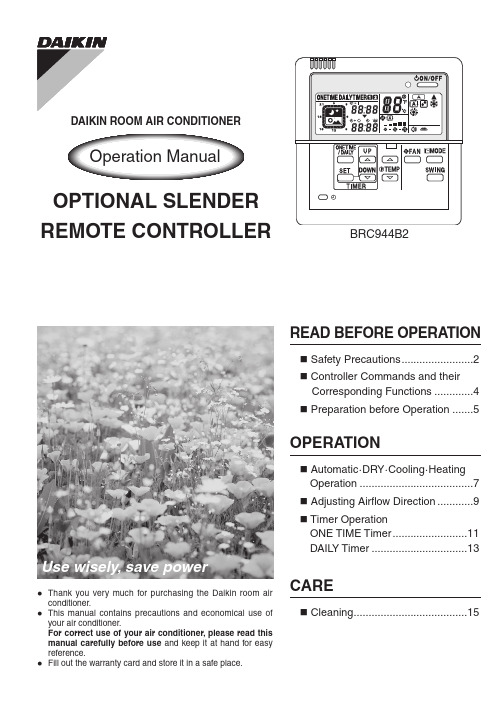
BRC944B2DAIKIN ROOM AIR CONDITIONEROperation ManualOPTIONAL SLENDER REMOTE CONTROLLERThank you very much for purchasing the Daikin room air conditioner.This manual contains precautions and economical use of your air conditioner.For correct use of your air conditioner, please read this manual carefully before use and keep it at hand for easy reference.Fill out the warranty card and store it in a safe place.Use wisely, save powerSafety Precautions ........................2 Controller Commands and their Corresponding Functions .............4 Preparation before Operation . (5)READ BEFORE OPERATIONAutomatic ·D RY ·C ooling ·H eating Operation ......................................7 Adjusting Airflow Direction ............9 Timer OperationONE TIME Timer .........................11DAIL Y Timer .. (13)OPERATIONCleaning (15)CARE2Safety Precautions•Keep this manual where the operator can easily find it.•Read this manual carefully before starting the unit.•For safety reason, the operator must read the following cautions carefully.•This manual classifies precautions into DANGER, WARNING and CAUTION. Be sure to follow all precautions below: they are all important for ensuring safety.DANGER•For refrigerant leakage, consult your dealer.Refrigerant gas is heavier than air and replaces oxygen. A massive leak could lead to oxygen depletion, especially in basements, and an asphyxiation hazard could occur leading to serious injury or death.•Refrigerant gas may produce a toxic gas if it comes in contact with fire such as from a fan heater, stove or cooking device. Exposure to this gas could cause severe injury or death.•Any abnormalities in the operation of the air conditioner such as smoke or fire could result in severe injury or death. Turn off the power and contact your dealer immediately for instructions.•Do not install the unit in an area where flammable materials are present due to risk of explosion resulting in serious injury or death.•If equipment utilizing a burner is used in the same room as the air conditioner, there is the danger of oxygen deficiency which could lead to an asphyxiation hazard resulting in serious injury or death. Be sure to ventilate the room sufficiently to avoid this hazard.•Safely dispose of the packing materials.Packing materials, such as nails and other metal or wooden parts, may cause stabs or other injuries. Tear apart and throw away plastic packaging bags so that children will not play with them. Children playingwith plastic bags face the danger of death by suffocation.WARNING•It is not good for health to expose your body to the air flow for a long time.•Do not put your finger, a rod or other objects into the air outlet or inlet. As the fan is rotating at a high speed and could, cause injury. Always keep small children away from the unit during operation.•Do not attempt to repair, relocate, modify or reinstall the air conditioner by yourself. Incorrect work or modifications could cause electric shocks, fire or other damage.For repairs and reinstallation, consult your Daikin dealer for advice and information. Never do.Be sure to follow the instructions.Be sure to ground the air conditioner.Never cause the air conditioner (including the remote controller) to get wet.Never touch the air conditioner (including the remote controller) with a wet hand.CAUTION•The air conditioner must be grounded to the earth. Improper grounding may result in electricshocks. Do not connect the earth grounding wire to a gas pipe, water pipe, lightning rod, or atelephone ground line. Follow all local and state electrical codes.authorized dealer if relocation is necessary for moving or remodeling.3Controller Commands and their Corresponding Functions45Preparation before OperationChecking the powerIf nothing appears on the remote controller's display, turn on the circuit breaker.Setting the current time1231Celsius temperature is indicated.Preparation before Operation2the Fahrenheit temperature isindicated.Setting Temperature Indication changeTemperature indication can be changed between Celsius and Fahrenheit before use.1Each time the button is pressed, the modechanges as follows.The system does not have the FAN mode.Automatic ·D RY ·C ooling ·H eating Operation2.The run indicator lamp lights up.Select your desired operation mode.Once preset, the system can get restarted in the same operation mode.Cooling onlymodelHeat pumpmodelThe run indicator lamp goes out.To adjust the temperature and airflow rate:To adjust the airflow direction:( page 9)When the unit runs in the cooling or heating mode at a low airflow rate, the cooling or heating effect may be insufficient.Adjusting Airflow Direction1 .Each time the button is pressed, the airflow direction louvers change their movement.Adjust the airflow direction for maximum comfort.W all Mounted Types (without horizontal swing function)The horizontal airflow direction louvers move up and down.The louvers stop just when the button is pressed.W all Mounted Type (with horizontal swing function)The horizontal airflow direction louversmove up and down.The horizontal airflow direction louversstop just when the button is pressed.Then the vertical ones start movingright and left.The vertical airflow direction louversstop just when the button is pressed.The vertical and horizontal louvers cannot move at the same time.D uct Connected Type (without swing function)This function cannot be used.Timer OperationTo select the ONE TIME timermode:1PEach time the button is pressed,the modes change as follows.The Timer Operation feature automatically turns off operation when you go to sleep and turns it back on when you wake up.Use the DAIL Y Timer mode on weekdays, and the ONE TIME timer mode on weekends.To cancel the timer settings:1(Timer settings displayed) The timer lamp lights up.The ONE TIME orDAIL Y TIMER disappearsfrom the display, and thetimer lamp goes out too.1P to select the ONE TIME timer.2P3PONE TIME timerOnce the timer has been activated and then deactivated, it is in the OFF mode.The ON or OFF timers can be programmed.light up.ONE TIMEEach time the button is pressed,the setting changes in a 10-minute increment or decrement.Hold the button down to advancequickly.When the ON timer is not used,save the setting as4P5P6PBoth of the ON and OFF timecannot be set assave the setting as .Timer OperationTo select the DAIL 1 P change as follows.1 The timer lamp lights up.(Timer settings displayed)1to select the DAIL Y timer.2Make the ON and OFF time settings. T ake the steps from to .Program example: 8:00 ~ 10:00, and 18:00 ~ 23:00DAIL Y timerAfter programming, the system starts and stops each day at the preset times. T wo pairs of time settings can be programmed.(Example: 8:00~10:00, and 18:00 ~ 23:00)lights up.3P Y timer is now programmed.CleaningM08B096(0807)3P202922-2B AKHTTwo-dimensional bar code is a code for manufacturing.。
大金空气净化器说明书
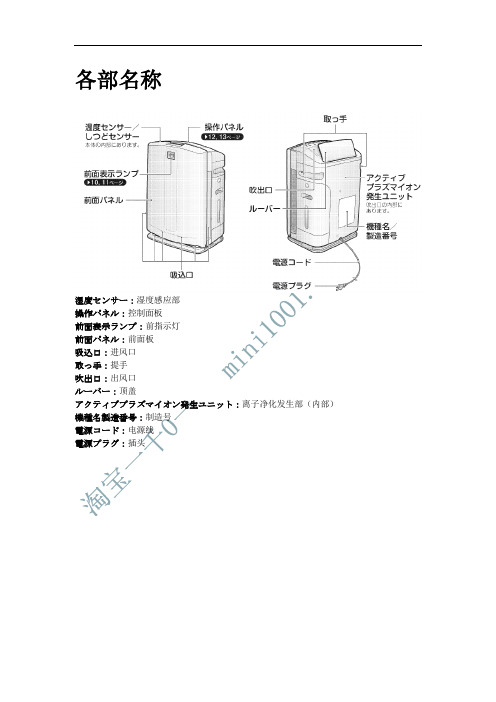
各部名称湿度センサー:湿度感应部操作パネル:控制面板前面表示ランプ:前指示灯前面パネル:前面板吸込口:进风口取っ手:提手吹出口:出风口ルーバー:顶盖アクティブプラズマイオン発生ユニット:离子净化发生部(内部)機種名製造番号:制造号電源コード:电源线電源プラグ:插头前面パネル:前面板プレフィルター:前置滤网脱臭フィルター:除臭滤网集塵フィルター:集尘滤网ユニット1(プラズマイオン化部):滤芯(离子化部)ユニット2(ストリーマユニット):滤芯2(流光净化部)ニオイセンサー:异味感应器ホコリセンサー:灰尘感应器安全ガード:安全网加湿フィルターユニット:加湿滤芯水タンク:水箱加湿トレー:加湿托盘送風ファン:风扇フロート:卡扣(禁止拆卸)銀イオンカートリッジ:银离子感应芯片使用前的准备前面指示灯お知らせランプ:提示灯。
与滤芯1,2和加水指示灯同时亮。
ハウスダスト:灰尘指示灯。
分为绿色,橙色,红色。
正常时为绿色,中等灰尘为橙色,严重为红色。
(开后7秒内一直为绿色,是检测中)ニオイ:异味指示灯。
分为绿色,橙色,红色。
正常为绿色,中等为橙色,严重为红色。
插拔电源和重按前面板后,开机第一分钟内显示为绿色。
水除菌中:加湿工作时会亮。
現在湿度目安(%):现在湿度指示器。
表示范围20%到90%之间。
低于20%时,显示为20。
高于90%时,显示为90%。
控制面板ユニット1洗浄:滤芯1需要清洗时会亮ユニット2洗浄:滤芯2需要清洗时会亮給水:水箱没有水时会亮(没有水时,空气净化机也可以单独使用)会有PPP的提示音2秒押し:长按两秒{表示ランプ(明暗切)}控制面板会锁住,可以仿制小孩误操作表示ランプ(明暗切):指示灯亮度调节键,分别是亮,暗,关闭。
切タイマー:定时关机键,按一下是1小时,两下是两小时,三下是4小时,四下是停止定时关机,相应指示灯会亮。
入タイマー:定时开机键,按一下是4小时后,两下是6小时后,三下是8小时后,四下是停止定时开机,相应指示灯会亮。
商品说明书健康家电空气净化器的使用与清洁方法

商品说明书健康家电空气净化器的使用与清洁方法商品说明书:健康家电空气净化器的使用与清洁方法一、引言空气净化器是现代家庭中必备的健康家电之一,它能够有效地净化室内空气中的有害物质,提供一个更加清洁和舒适的生活环境。
本篇说明书旨在向用户介绍健康家电空气净化器的正确使用方法及清洁注意事项。
二、使用方法1. 放置位置选择健康家电空气净化器适用于各种室内环境,但应避免阳光直射和潮湿的地方。
选择放置在通风良好、无遮挡物的地方,以确保充足的空气流通。
2. 连接电源将空气净化器插头连接到电源插座,并确保电源供应稳定。
请不要将空气净化器插头与其他电器共用一个插座,以免发生电气故障。
3. 打开开关找到空气净化器的开关,并将其切换至“开启”状态。
此时,指示灯亮起,表示空气净化器已经启动工作。
4. 调节风速根据需求,选择合适的风速档位。
通常情况下,一般的家庭环境可选择低档,而特殊环境或者对空气质量要求较高的场所可选择高档。
5. 定期更换滤芯空气净化器的滤芯是保证其正常工作的重要组成部分。
根据使用频率和环境污染程度,建议每2-3个月更换一次滤芯,以确保过滤效果的持续。
三、清洁方法1. 断电和拆卸在进行清洁之前,务必先将空气净化器断电并拔掉电源插头。
然后,按照用户手册的指引,小心拆卸和取出滤芯,以便更好地清洁各个部件。
2. 清洗外观使用柔软的湿布或者中性清洁剂,轻轻擦拭空气净化器的外壳和控制面板,去除灰尘和污渍。
切勿使用酸性或碱性清洁剂,以免损坏外壳的表面。
3. 清洗滤芯根据滤芯材质和型号的不同,可选用水洗或抖动的方式清洗滤芯。
若采用水洗方式,请注意用清水冲洗,切勿使用洗涤剂或化学物质。
4. 晾干和安装清洗后的滤芯应晾干,确保没有残留水分。
然后按照正确的方向和位置重新安装滤芯到空气净化器中。
5. 定期检查为了保证空气净化器的正常运行和过滤效果,建议每2-3个月对其进行一次全面的检查,包括滤芯的清洁和更换、风道的排污等。
四、注意事项1. 儿童禁止操作由于空气净化器有电器连接和高转速风扇等部件,儿童在使用时应在成人的监护下进行。
