电力物联网汇聚节点使用手册
UT-IBS3.0节点使用手册
UT-IBS3.0节点使用手册1. 综述 (2)2. 系统结构 (2)2.1 管理结构 (2)2.2名词解释(术语说明): (3)3. 计费节点管理员 (4)3.1 Web界面: (4)3.2 增加新营业员 (5)3.3 修改经理密码 (5)3.4 修改营业员信息 (5)3.5 查询及修改用户 (5)3.6 查询及修改帐户 (5)3.7 用户停用 (5)3.8 帐户停用 (6)3.9 删除帐户 (6)3.10 启动用户 (6)3.11 启动帐户 (6)3.12 营业员及所开用户,帐户信息总览 (7)3.13 营业员及所开用户资费信息总览 (7)3.14 联合查询 (7)3.15 统计 (8)4. 营业员 (9)4.1 Web 界面: (9)4.2 增加新用户及帐户 (10)4.3 修改营业员密码 (14)4.4 设置帐户密码 (14)4.5 查询用户 (14)4.6 查询帐户 (14)4.6 已开用户信息总览 (15)4.7 已开帐户信息总览 (15)4.8 帐户资费信息总览 (16)4.9 统计 (16)5. 普通用户 (17)Web 界面: (17)6. 常见问题处理 ....................................................................................................... 错误!未定义书签。
1. 综述本系统是 UT斯达康公司为中国大、中型 ISP 设计、开发的 Internet 用户管理与计费系统。
它的主要特点有:分布式的体系结构、层次式的管理结构与集中式数据库处理相结合;●数据传输采用 SSL、 DES 等加密手段,安全性强;●系统使用分中心管理员、节点管理员、业务员和普通用户四个层次,结构清晰、管理方便;●拨号、专线、漫游用户用相同界面统一管理,计费、折扣政策用填表方式实现,灵活、方便;●基于 HTML 的用户界面,操作简单、易学,不需专门软件,用户可从网络上查询自己的使用明细、折扣和费用系统提供管理类型有:●PPP 拨号管理●TERMNAL 拨号管理●专线用户管理●漫游用户管理系统支持的用户类型有:●PPP拨号用户----用户具有拨号上网的权限,同时拥有email信箱●SHELL用户----用户具有telnet权限●专线用户---DDN用户●只有MAIL用户---用户只有mail帐号,不能拨号上网●PPP+SHELL拨号用户---用户具有拨号上网和telnet权限●个人主页用户---将个人主页连接到www服务器●PPPWithoutMail用户---用户具有拨号上网的权限,但不拥有email信箱●LimitedPPP用户---用户具有拨号上网的权限,同时拥有email信箱,但对同时上网人数进行限制●RealtimePPP用户---一次性PPP用户(尚未实现)●Vhost用户---虚拟主机用户,用户的www服务器为用户名.domain本系统分为计费中心系统和计费节点系统两部分。
最新集中器使用手册

集中器使用手册集中器使用说明书一、概述 (3)二、执行标准 (3)三、系统特点 (3)四、主要技术指标 (4)4.1 基本参数 (4)4.2 硬件组成表 (5)4.3 软件构成表 (5)五、功能配置表 (6)六、工作原理 (7)6.1 工作原理简述 (7)6.2 硬件原理图 (8)6.3 软件流程图 (9)6.4现场拓扑图 (10)6.5系统架构图 (11)七、外观及端子说明 (12)7.1 安装尺寸图 (12)7.2 外观结构示意图 (13)7.3 接线图 (13)八、操作说明 (14)8.1 操作流程 (14)8.2 安装说明 (16)8.3 指示灯 (16)8.4 主站操作说明 (17)8.5 界面操作说明 (18)8.6 短信控制说明 (18)8.7 级联操作说明 (19)8.8 升级操作说明 (20)九、初始化 (21)9.1 集中器核心板程序烧写流程 (21)9.2 集中器功能测试流程 (43)9.3集中器常见故障处理 (47)十、维护 (49)十一、注意事项 (49)一、概述集中器是集抄系统中心管理设备负责主站命令的传送,抄表数据的存储,自动抄表任务的执行与事件的记录等功能。
二、执行标准《Q/GDW 374.2-2009电力用户用电信息采集系统技术规范:集中抄表终端技术规范》《Q/GDW 375.2-2009电力用户用电信息采集系统技术规范:集中器型式规范》《Q/GDW 376.1-2009电力用户用电信息采集系统技术规范:主站与采集终端通信协议》《Q/GDW 376.2-2009电力用户用电信息采集系统技术规范:集中器本地通信模块接口协议》三、系统特点◆工业级32位ARM9处理器和Linux嵌入式系统与嵌入式数据库技术。
◆同时支持无线、晓程、东软等本地模块的模块路由模式或集中器路由模式。
◆智能的集中器中继路由抄表算法(基于嵌入式数据库数据挖掘统计分析能力与速度),配主流厂家的芯片现场平均每户3到4秒的实时表码抄表速度与100%的实时抄到率。
WTOS-02H系列汇聚型数字视频光端机用户手册v1.0版
数字光纤传输产品使用手册
3.汇聚式设备功能型号对照表
序号 前端设备 1 路视频+1 路双向音频+1 1 HT1D-ADK 路总线 RS485 控制数据+1 路报警开关量发射机 1 路视频+1 路总线 RS485 2 3 汇聚点设备 4 5 HC40D HC80D 4 光纤方向汇聚点设备 8 光纤方向汇聚点设备
2 产品特点
WELLTRANS WTOS-02H 系列汇聚型数字光端机汇聚型光端机可 以实现 4 或 8 个前端的接入,最多传输 8 路非压缩数字视频。汇聚 型光端机分两级进行传输, 首先前端将模拟视频信号数字化后转换 成光信号,并经光纤传输到汇聚点;汇聚点先将各路光信号还原成 高速数字电信号,再对多路信号进行高速复接后转换成光信号,再 经光纤送往接收端; 接收端将收到的所有数字视频信号恢复成模拟 信号输出。在汇聚点只完成光-电(复接)-光的转换,信号不被还 原成模拟信号。汇聚式系列光端机支持微创 eGuide 网管系统,网 管系统的安装和开通详见网管系统说明书。 汇聚式光端机的组网系 统结构图如下所示:
6
HC31D-ADK
双向音频+1 路总线 RS485 控制数 据+1 路报警开关量汇聚点设备
3 方向支持本地 1 路视频+ 7 HC31D-DK 1 路总线 RS485 控制数据+ 1 路报警开关量汇聚点设备 4 光纤方向支持本地 1 路视 8 HC41D-ADK 频+1 路双向音频+1 路总线 RS485 控制数据+1 路报警 开关量汇聚点设备 4 方向支持本地 1 路视频+ 9 HC41D-DK 1 路总线 RS485 控制数据+ 1 路报警开关量汇聚点设备
3 光纤方向支持本地 1 路视频+1 路
型
号
FTR-01中文说明书2008-10-27故障录波

FTR-01 电力系统故障录波及分析装置用户手册FTR-01H 便携式电力系统故障录波及分析装置用户手册武汉方得电子有限公司Wuhan Fount Electronics Co., Ltd.Document Number WH40-9101-03 Version 2008-10-27FTR-01电力系统故障录波及分析装置用户手册FTR-01H便携式电力系统故障录波及分析装置用户手册本手册内容如有更改,恕不通告。
没有武汉方得电子有限公司的书面许可,本手册任何部分都不许以任何(电子的或机械的)形式、方法或以任何目的而进行传播。
是武汉方得电子有限公司的商标ReplayB 是武汉方得电子有限公司的商标Windows 是微软公司的商标所有其他公司的商标和知识产权在本手册中都予以认可©2008武汉方得电子有限公司版权所有中华人民共和国湖北省武汉市东湖开发区关山二路特1号国际企业中心栖凤楼B座4层电话 +86 027 8266 8396传真 +86 027 6784 8757邮政编码 430074E-mail: whft@Information of modifying2007-07-03 2007-07-04 2007-07-05 2007-07-09 2007-07-10 2007-07-12 2007-07-13 2007-07-18 2007-07-20 2007-11-02 2008-07-21 2008-09-22 2008-10-27FTR-01型电力系统故障录波及分析装置用户手册I目录第一章FTR-01的系统功能及技术指标.......................................................................................... 11.1装臵概述.......................................................................................................................................... 11.1.1用途............................................................................................................................................. 11.1.2FTR-01结构体系 .................................................................................................................... 11.1.3输入信号.................................................................................................................................... 11.2系统新特性 ..................................................................................................................................... 11.2.1软件与硬件 ............................................................................................................................... 11.2.2高抗干扰性 ............................................................................................................................... 21.2.3专用DSP ................................................................................................................................... 21.2.4高速的PCI总线 ..................................................................................................................... 21.2.5工频信号自动频率跟踪 ........................................................................................................ 21.2.6采集单元远距离分布式安装 ............................................................................................... 21.3主要技术指标................................................................................................................................. 21.4设备的选配................................................................................................................................... 41.4.1设备型号的定义...................................................................................................................... 41.4.2开关量扩展 ............................................................................................................................... 41.4.3可供选用的型号...................................................................................................................... 4第二章FTR-01的被测输入量的接入 .............................................................................................. 52.1交流电压量的接入 ..................................................................................................................... 52.2交流电流量的接入 ..................................................................................................................... 52.3开关量的接入 .............................................................................................................................. 62.4数据采集单元(RAU)量程的硬件调整.................................................................................. 7第三章FTR-01的面板功能 ................................................................................................................ 83.1FTR-01前面板............................................................................................................................... 83.2面板功能.......................................................................................................................................... 83.2.1状态指示灯 ............................................................................................................................... 83.2.2液晶屏功能指示...................................................................................................................... 83.3功能菜单.......................................................................................................................................... 93.4功能菜单的使用 ........................................................................................................................ 103.4.1通道监控................................................................................................................................ 103.4.2记录列表................................................................................................................................ 103.4.3打印机配臵 ........................................................................................................................... 113.5FTR-01后面板与功能 ............................................................................................................. 123.5.1FTR-01后面板布臵............................................................................................................ 123.5.2FTR-01后面板结构与功能 .............................................................................................. 123.6RAU后面板与功能.................................................................................................................. 133.6.1RAU后面板 .......................................................................................................................... 133.6.2RAU后面板布臵与功能 ................................................................................................... 13第四章软件“FTR录波器管理系统”....................................................................................... 14IIFTR-01型电力系统故障录波及分析装置用户手册什么是“FTR录波器管理系统”........................................................................................ 144.2“FTR录波器管理系统”运行环境...................................................................................... 144.3FTR-01与后台的连接 ............................................................................................................. 144.3.1网络物理连接....................................................................................................................... 144.3.2网络连通的试验.................................................................................................................. 144.4使用M ODEM进行远方传送................................................................................................... 154.5安装和运行软件“FTR录波器管理系统”...................................................................... 164.6FTR录波器管理系统(R EPLAY B)件................................................................................ 174.7FTR录波器管理系统(R EPLAY B)对FTR-01设备群的管理.................................... 184.7.1在软件ReplayB中添加子站名称及设备名称............................................................ 184.7.2获取FTR-01的前台配臵.................................................................................................. 19第五章FTR-01输入通道属性的描述与起动的整定............................................................... 205.1模拟通道属性的描述............................................................................................................... 205.2模拟通道起动录波的设臵...................................................................................................... 215.3开关量输入通道属性的设臵 ................................................................................................. 225.4记录格式的设定 ........................................................................................................................ 235.4.1瞬态故障DFR(Disturbance Fault Recording)记录格式的设臵 ....................... 235.4.2连续稳态记录CSS(Continuous Steady State recording)记录格式的设臵 ...... 24第六章FTR-01的校准 ..................................................................................................................... 256.1校准信号源设备的准备 .......................................................................................................... 256.2确定硬件量程和通道配臵...................................................................................................... 256.3FTR录波器校准软件R EPLAY C AL 的使用 ......................................................................... 25第七章FTR-01故障记录的读取 ................................................................................................... 287.1在R EPLAY B中选定目标设备................................................................................................ 287.2设臵数据抽取策略.................................................................................................................... 297.3瞬态故障记录文件DFR(D ISTURBANCE F AULT R ECORDING)的提取 ...................... 297.4连续式稳态记录CSS(C ONTINUOUS S TEADY S TATE RECORDING)文件的提取...... 307.5触发式稳态记录TSS(T RIGGERED S TEADY S TATE RECORDING)文件的读取 ......... 317.6故障记录文件的断点续传...................................................................................................... 32第八章使用软件CMDVIEW观察分析故障记录................................................................... 348.1打开故障记录............................................................................................................................. 348.2C MD V IEW工具栏图标的功能................................................................................................ 358.3选择显示通道............................................................................................................................. 368.4通道交换显示位臵.................................................................................................................... 368.5改变波形和背景的颜色 .......................................................................................................... 368.6使若干通道幅度的比例尺一致与通道的叠加.................................................................. 378.7移动时标...................................................................................................................................... 378.8记录排序与检索 ........................................................................................................................ 388.9记录的E XCEL格式输出.......................................................................................................... 388.10记录的COMTRADE格式输出 .......................................................................................... 398.11记录的打印输出 ........................................................................................................................ 39第九章在CMDVIEW中输入线路参数信息 ............................................................................ 40FTR-01型电力系统故障录波及分析装置用户手册III “定义线路”的概念............................................................................................................... 409.2在C MD V IEW中定义线路的方法 .......................................................................................... 409.3定义线路参数表的应用 .......................................................................................................... 41第十章FTR-01互感器配臵 ............................................................................................................ 4210.1互感器(或其他传感器)的配臵 ...................................................................................... 42第十一章用计算量起动FTR-01与稳态量录波的指定.......................................................... 4511.1计算量的概念............................................................................................................................. 4511.2设臵计算量起动录波............................................................................................................... 4511.3连续稳态量CSS(C ONTINUOUS S TEADY S TATE RECORDING)记录内容的指定...... 47第十二章用FTR-01实时监测电力系统的远程模拟盘.......................................................... 4812.1实时监测的概念 .................................................................................................................... 4812.2用户自行设计的实时监测界面......................................................................................... 4812.3在系统图中添加监测点 ...................................................................................................... 49第十三章FTR-01日志查阅............................................................................................................. 5013.1FTR-01的日志....................................................................................................................... 5013.2FTR-01日志读取方法 ......................................................................................................... 50第十四章用保护动作量起动FTR-01........................................................................................... 5114.1保护动作量起动录波的慨念 ............................................................................................. 5114.2设臵保护动作量起动录波.................................................................................................. 5114.3各种保护动作量的整定 ...................................................................................................... 5314.3.1发电机比率制动式纵差保护(DL/T 684-1999, P2, 4.1.1) ....................................... 5314.3.2发电机标积制动式纵差保护(DL/T 684-1999, P4, 4.1.2) ....................................... 5314.3.3发电机故障分量比率制动式纵差保护(DL/T 684-1999, P4, 4.1.3)..................... 5414.3.4发电机单元件横差保护(DL/T 684-1999, P6, 4.1.5b).............................................. 5414.3.5发电机纵向零序过电压保护(DL/T 684-1999, P8, 4.1.7) ....................................... 5514.3.6发电机故障分量负序方向保护(DL/T 684-1999, P8, 4.1.9)................................... 5514.3.7发电机三次谐波电压单相接地保护(DL/T 684-1999, P10, 4.3.2a)..................... 5614.3.8发电机阻抗法低励失磁保护......................................................................................... 5614.3.9以系统两点间相位差为依据的失步保护 .................................................................. 5714.3.10发电机定子铁心过励磁保护(DL/T 684-1999, P24, 4.8.1)................................. 5714.3.11发电机频率异常保护(DL/T 684-1999, P24, 4.8.2)............................................... 5814.3.12发电机逆功率保护(DL/T 684-1999, P24, 4.8.3) ................................................... 5814.3.13发电机定子过电压保护(DL/T 684-1999, P24, 4.8.4).......................................... 5814.3.14变压器纵差保护(DL/T 684-1999, P25, 5.1)........................................................... 5914.3.15变压器零序差动保护(DL/T 684-1999, P31, 5.3.1)............................................... 5914.3.16变压器过流保护(DL/T 684-1999, P32, 5.5.1 P33, 5.5.2) .............................. 6014.3.17空载投运变压器保护................................................................................................... 6014.3.18启停机保护(DL/T 684-1999, P25, 4.8.5)................................................................. 60第十五章FTR-01用于电力设备的试验 ...................................................................................... 6115.1试验的抽象 ............................................................................................................................. 6115.2试验的设计 ............................................................................................................................. 6215.2.1可选择的试验变量 ........................................................................................................... 62IVFTR-01型电力系统故障录波及分析装置用户手册支持直角坐标、极坐标 .................................................................................................. 6215.2.3支持多种试验并行 ........................................................................................................... 6215.3虚拟试验.................................................................................................................................. 62第十六章FTR-01故障记录的分析 ............................................................................................... 6316.1序分量分析 ............................................................................................................................. 6316.2谐波分析.................................................................................................................................. 6316.3故障测距.................................................................................................................................. 6416.4阻抗轨迹分析......................................................................................................................... 6516.5通道波形整合......................................................................................................................... 6516.6计算量显示 ............................................................................................................................. 66第十七章 FTR-01H便携式故障录波器.......................................................................................... 6717.1FTR-01H便携式故障录波器外形 ..................................................................................... 6717.2FTR-01H便携式故障录波器的可识别适配器............................................................... 6717.3FTR-01H便携式故障录波器的使用................................................................................. 6817.4FTR-01H便携式录波器适配器的接入 ............................................................................ 6917.5FTR-01H更换适配器模块后的操作说明........................................................................ 6917.6FTR-01H便携式录波器的网络连接电缆........................................................................ 69附录Ⅰ:FTR-01使用流程图.......................................................................................................... 71附录Ⅱ:FTR-01瞬态故障录波时段组成和故障记录时限................................................... 72FTR-01型电力系统故障录波及分析装置用户手册1第一章FTR-01的系统功能及技术指标1.1 装臵概述1.1.1 用途FTR-01型电力系统故障录波及分析装臵广泛地应用于电力系统,记录发电机、变压器、电力输送线路、电站、电厂的瞬态、稳态模拟量与事件量信息,监视电力系统运行,保存试验数据,记录和捕捉故障信息,为研究电网运行方式及评价保护装臵的性能提供依据。
电能电网门户900用户指南说明书
Power Xpert Gateway 900Product snapshotThe Power Xpert® Gateway 900 (PXG 900)has been designed to be installed in electrical assemblies or systems—low- and medium-voltage switchgear, switchboards, panelboards, transfer switches, and motor control centers to acquire and consolidate data available from components such as trip units, meters, relays, drives, and I/O. Product overview• Open communication architecture• Connects to both Eaton and third-partyelectrical equipment; communicatesto INCOM E, Modbus T TCP, andModbus RTU devices• Modbus TCP, BACnet/IP and SNMP v.1 / v.3support facilitates integration withthird-party monitoring solutions• Ethernet/web-based support uses yourexisting network infrastructure, reducing costs • Flexible and expandable solutions• Stand-alone or small systems benefit fromcomprehensive, on-board web pages; noadditional programming or software isnecessary for virtually out-of-the-box,plug-and-play functionality• Larger systems, such as campus installationsor power systems with remote locations canview multiple PXGs via Foreseer or PowerXpert Energy Visualization and Analytics or athird-party monitoring system• Existing equipment can be connected tothe PXG at minimal cost, without the needto upgrade• Information at a glance• Private Network mode on the Net 2port will allow for the ability to establisha private subnet to attach Modbus TCPcommunication devices• Using a standard web browser, view thePXG’s web interfaces that include a Networktab, Alarms tab, individual device detailpop-outs, and One Line graphics tab• Comprehensive, well-organized device webpages present measured parameters such ascurrent, voltage, power, energy, frequency,power factor, and voltage THD, just to namea few• Combine with Foreseer or Power XpertEnergy Visualization and Analytics (PX-EVA)for viewing multiple gateways and otherpower system equipment for more extensiveenergy monitoring and capacity analysisDelivers real-time, web-enabled monitoring of electrical distribution and control equipment2Technical Data TD152008ENEffective June 2021Power Xpert Gateway 900EATON Monitoring power and energy in a networked worldThrough standard on-board web pages, Foreseer or PX-EVA, orthird-party software, Eaton’s Power Xpert Gateway (PXG) 900 allows you to closely monitor the performance of your power and energy efficiency with easily accessed, real-time, web-enabled data. Eaton’s PXG 900 provides a central point to connect devices to an Ethernet network. The gateway may be used as a standalone device to view one system or location, or it can be easily integrated into a large, multi-location system.The PXG is our configurable data acquisition solution for facility equipment like switchgear, switchboards, motor control centers, etc. Power and energy data from the downstream devices are time stamped and stored in non-volatile memory. This interval data can be stored or updated to a destination of the user’s choice through CSV . Data can also be accessed through any web browser directly on the PXG. Users can move data into Foreseer, PX-EVA, BMS, BAS, building dashboards, custom software applications, or virtually any web interface.Features and benefitsRugged, industrial design•Designed specifically for industrial environments, the PXG has a compact design that only requires convection cooling•Stringent EMI design requirements ensure that the PXG willfunction in the most difficult EMI situations to deliver high reliability •Mounting options are provided for panel mounting or DIN rail, allowing for installation flexibilitySmart configuration and user interface•As an out-of-the-box, plug-and-play device, there is no additional software required to configure and view downstream devices • All configuration menus are straightforward and easy to follow •Upon configuring the PXG and associated devices, the data will automatically appear in the web UI when you point your browser to the IP address of the PXGT wo operational modesThe Power Xpert Gateway can operate in two modes, simultaneously if required, providing flexibility for varying protocols, devices, and systems. For further details of each operational mode, see user manual. For a graphical representation of each mode, see Figure 1.1. Modbus RTU to Modbus TCP Pass-Through andModbus TCP Pass-Through modeThe Modbus RTU-Modbus TCP Pass-Through mode allows information from Modbus serial devices to pass directly through the gateway to be viewed by a (or multiple)Modbus TCP monitoring software, i.e., an existing Building Management System.−The PXG allows users to do simple protocol translation,with minimal configuration in the PXG for those applications where they need Modbus TCP to bring devices into their existing system.−The flexibility of the PXG for simple Modbus protocol translation in conjunction with other mode’s makes the PXG more than a simple Modbus protocol translator.2. Web browser or Cache modeCache mode allows data from INCOM serial devices and Modbus RTU and TCP devices into the gateway, creating real-time viewing status through a web browser as well as logging for historical reference and trending. Cached data from the connected devices can be shared with other client software similar to pass through.−The PXG in Cache mode serves as an acquisition tool and provides the ability for users to view their devices on the ports connected to the PXG through a web browser. This allows users to bring power infrastructure equipment online to monitor operation and record power and energy usage.The Power Xpert Gateway also supports legacy PowerNet Esystems. Expansion of an existing PowerNet system with additional equipment can be easily achieved by adding a PXG 900 to the system to bring the INCOM communicating devices online via INCOM pass-through.INCOM pass-through allows data from INCOM serial devices to flow directly through the gateway to be viewed in PowerNet software for logging and consolidation with other connected devices.ote: N INCOM serial communication can either be cached or pass-through, not both at the same time.Secure cyber communicationControlling access to the PXG 900 is a vital component in any effort to secure it. Many regulatory agencies and standards organizations now recommend/require Role-Based Access Control (RBAC) password management and previous login notification as part of any access control effort. To support this, the PXG 900 has a robust set of tools you can use to create the set of users and role-based permissions with password management you need to comply with security policies in effect at your site.•Password protection and managementRole-Based Access Control (RBAC) as part of any access control effort. To support this, the PXG 900 has a robust set of tools you can use to create the set of users and role-based permissions as well as a comprehensive set of password management features you need to comply with security policies in effect at your site •Secure web browsingSSL Encryption option ensures that information and passwords exchanged with the PXG’s web server cannot be intercepted on the LAN•Access control / trusted host listProvides an additional method of security by limiting access to the communication ports by authorized trusted hosts’ IP addresses •Third-party certificatesSupports the use of third-party certificates to ensure that all connected devices are securedTime synchronizationThe PXG supports synchronization of clocks on INCOM devices that support the set time and date command. Additionally, the PXG can be combined with a network time server for accurate time stamping via NTP .3Technical Data TD152008ENEffective June 2021Power Xpert Gateway 900 EATON Cached data modeModbus modeCached dataPass-through Modbus RTU-TCPModbus serial devices Modbus TCP devicesINCOM serial devices Modbus serial devices Modbus TCP devicesPowerPort-EWeb browserModbus masters Figure 1. T wo operational modesReal-time trending and viewingThe PXG 900 allows the user to enable pre-selected parameters to be trended for each supported device. This feature is user-selectable on the device configuration page. A trend symbol is displayed next to the trended parameter on the device page. Selecting the trend symbol will generate a real-time graph via the web UI for that parameter and can be viewed for the past 24 hours, 7 days, 30 days or all past history.T rend and alarm logging and analysisThe PXG 900 stores both historical data and alarms that can be downloaded into a comma separated value (CSV) file format. Using Excel ® will allow you to perform analysis to discover potential system issues or proactively perform maintenance.Waveforms capture and downloadsThe PXG 900 supports waveform acquisition for INCOM supported devices capable of generating waveforms. This feature is user-selectable on the device configuration page. The waveform files are converted and stored as a COMTRADE file format in the PXG 900. The files can then be downloaded and viewed using a standard COMTRADE waveform viewer of your choice.Email notifications related to captured waveforms is now available providing a link back to the waveform to be downloaded.ote: N The Eaton Power Xpert Gateway 900 includes the Power Xpert Gateway Module, USB A to Mini-B USB cable, and DIN rail adapter with mounting screws.4Technical Data TD152008ENEffective June 2021Power Xpert Gateway 900EATON Power Xpert Insight Gateway user interface Network tabDefault log-in screen that provides general configuration of the gateway, serial communication ports, and devices. The Network tab provides a simple view of the serial devices and their current status of operation by color changes and symbols. Additional detail and functionality is accessible from the Network tab sidebar for allcommunicating devices.Alarms tabProvides a single screen that provides details on all alarmsassociated with the device communicating in cache mode through the gateway. Alarms can be reviewed and acknowledged, as well as sorted and filtered based on status. Additional information regarding the alarm can be found by selecting the alarm and specifics on thealarm will be displayed in the sidebar.One-lines tabAllows users the ability to create a graphical representation of a one- line diagram based on the user’s desired representation. Through the device tree, a user can select devices and group them in locations and generate a multiple level one-line representing the devices connected to the gateway. The one-line graphic will provide device status graphically, and additional detail can be found on the device and its supported channels in the sidebar of a selected device onthe one-line or device tree.Device details and trend viewerSelected devices on the Network tab and One-lines tab provide a device sidebar. From that sidebar, a user can get additional detail about the device and its monitored channels, by selecting thechoose an action menu on the sidebar. This will allow users to see the device details pop-out as well as gain access to historical trenddata and other available information regarding the selected device.5Technical Data TD152008ENEffective June 2021Power Xpert Gateway 900 EATON User-defined alarmsThe PXG 900 supports the setting of user-defined alarms on an individual device and channel basis. This feature is set for enabled channels via the Setting button in the header under the alarmssetting tab. An example of a user-defined alarm would be a low and high limit on the phase A current channel for a device. The alarm limit values and the alarm names can be chosen by the user.Email notificationA user has the ability to customize and direct email to notifications to up to 10 users in their organization. Select from alarm notifications, waveform notifications, trend log, alarm log, and daily emails. This function provides yet one more way to effectively and proactively manage your monitored system.Save and restore configuration settingsThe PXG provides the ability to save the PXG device and network configuration settings to an XML file format. It can be used to restore settings to any PXG to facilitate configuration of similar systems.RS-485connections USB connection for local configuration capabilityPower StatusWebBridge Com2Com1INCOMDHCPNTP 24 Vdc input powerRJ-45 connections with link speed and activity indicatorsFigure 2. Power Xpert Gateway 900Figure 3. Power Xpert Gateway 900 with standard panel mountingFigure 4. Power Xpert Gateway 900 with DIN rail mounting (brackets included)6Technical Data TD152008ENEffective June 2021Power Xpert Gateway 900EATON Power Xpert Gateway enclosed versionEnclosed version•Cost-effective solution to add communications to new or existing equipment that has no physical space to install the PXG in the equipment structure • NEMA ® 12 enclosure rating•Prewired with a PSG60N24RP power supply and terminal blocksfor ease of wiring of incoming power and connected devicesFigure 5. Power Xpert Gateway enclosure dimensionsPXG daisy-chain application in bridge modeThe PXG allows for units to be connected together through two RJ-45 10/100/1000 connectors on the front of the PXG series of products. Default is bridged mode for the daisy-chain application. This arrangement is a pass-through of Ethernet communications, allowing a single network drop to connect up to five Ethernet communicating devices. The maximum length of a copper cable run should not exceed 295 ft (90 m) total.ote: N In this configuration, if any of the PXG units go offline or lose power, the communication to the downstream Ethernet devices will lose connection to the LAN.Supported device list for integratorsPlease visit /pxg for a list of supported devices.PXM2000Figure 6. PXG daisy-chain application7Technical Data TD152008ENEffective June 2021Power Xpert Gateway 900 EATON Technical specificationsT able 2. PXG part numbersDescriptionEatonstyle numberEatoncatalog numberPower Xpert Gateway 90066D2325G01PXG900Power supply—24 Vdc PSG60N24RP-A2PSG60N24RP Enclosed Power Xpert GatewayPXG900-2A Enclosed Power Xpert Gateway—480 V PXG900-2BMemory• Flash: 2 GB •RAM: 1 GBCommunication ports• Network ports: Two 10/100/1000BASE-T RJ-45 connectors •Serial ports−Two RS-485 ports for connection to Modbus RTU devices −One dedicated INCOM port for INCOM devices •Configuration port: One USB portNetwork protocols supported• Modbus TCP/IP: Supports data access from Modbus TCP clients •Web server: Supports data access from web browsers (HTTP and HTTPS)• DHCP: Supports automatic IP address assignments, if enabled •NTP: Supports time synchronization via a network time server for PXG synchronization• SMTP: Supports mail server for email notification • BACnet/IP: Supports data access from BACnet clients•SNMP v.1 / v.3: Supports data access from SNMP clients using the following supported MIBs (Eaton OIDs reference MIB, Eaton Alarms+Traps MIB, RFC 4133 Entity MIB,RFC 4268 Entity State MIB, Eaton Power Device MIB, and Eaton Power Meter MIB)Serial protocols supported• INCOM •Modbus RTUWeb browser recommended•Google ChromePower input• Input voltage, nominal: 24 Vdc; 0.3 A minimum •Input voltage range: ±10% nominalPower consumption•8 W maximumOperating temperature•+32 to +140 °F (0 to +60 °C)Ambient storage temperature•–40 to +185 °F (–40 to +85 °C)Relative humidity•5 to 95% noncondensing at 122 °F (50 °C)Size (H x D x L) in inches•2.00 x 4.50 x 6.00Weight•1.7 poundsSupported devices and performancePXG performance will vary depending upon the number and type of connected devices. This is driven by the following:•Each supported device has a distinct number of channels to report back to the PXG, ranging from as few as 4 to over 900• The channels are prioritized • Device protocol, Modbus or INCOM •Baud rate settingFor this reason, a PXG modeling tool has been developed to assist in understanding the expected performance for a givenapplication because all systems are unique. This tool can be found at /pxg. For a high level performance comparison, see the table below for three examples.How long does it takeFor this combination of devices (all times in seconds)64 INCOM/ 32 Modbus15 INCOM/15 Modbus 5 INCOMBetween value change in the UI (INCOM 9600)—Priority 121.9 3.7 1.4Between value change in the UI (Modbus 57600)—Priority 1 3.5 1.6—Between value change in the UI (INCOM 9600)—Priority 244.37.4 2.6Between value change in the UI (Modbus 57600)—Priority 27.0 3.1—Modbus server pass-through response time (57600) (local connection)0.0610.059—For the UI to show an alarm (INCOM device)17.0 3.0 3.0To boot up (all devices communicating)399.085.051.0Regulatory and standards compliance• UL ® 508, Standard for Programmable Controller Equipment • FCC, Class A, Part 15, Subpart B, Sections 15.107b and 15.109b •EN55022:2010/A1:2011 Class A and EN55024:2010 Information Technology Equipment•EN 61326-1:2006 and EN 61326-2-2:2006 Electromagnetic Compatibility (EMC) in Industrial Environmentsote: N Features and specifications listed in this document are subject to change without notice and represent the maximum capabilities of the product with all options installed. Although every attempt has been made to ensure the accuracy of information contained within, Eaton makes no representation about the completeness, correctness, or accuracy and assumes no responsibility for any errors or omissions. Features and functionality may vary depending on selected options.Eaton1000 Eaton Boulevard Cleveland, OH 44122 United States © 2021 EatonAll Rights ReservedPrinted in USAPublication No. TD152008EN / Z25105 June 2021Eaton is a registered trademark.All other trademarks are propertyof their respective owners.Power Xpert Gateway 900Technical Data TD152008EN Effective June 2021。
林洋能源 NLY1220 单相物联网电能表 使用说明书

NLY1220单相物联网电能表(单相电子式电能表)使用说明书(Ver1.0)江苏林洋能源股份有限公司目录一、概述 (1)二、产品规格 (1)三、主要技术指标 (1)3.1性能指标 (1)3.2无线技术参数 (2)四、外观结构及接线图 (2)4.1外形及结构尺寸 (2)4.2端子接线图 (3)五、安装与维护 (4)六、使用说明 (4)6.1面板说明 (4)6.2功能说明 (4)6.2.1计量 (4)6.2.2时钟 (5)6.2.3显示及特殊设置 (5)6.2.4抄表和电能管理功能 (5)6.3通讯说明 (6)6.3.1通信方式 (6)6.3.2通信协议 (6)七、调试 (7)八、运输存储 (7)九、售后服务 (7)一、概述NLY1220单相物联网电能表是针对新兴出租公寓能源管理市场开发的一款单相电子式电能表。
该产品应用在公寓或者集中建筑管理的场景中,通过WiFi通信方式把单相表采集数据传送给主站,有专业的第三方管理团队进行能源管理和运营服务。
对于公寓电表来说,通信稳定、低成本(表和通信)、安装方便、维护便利、数据可靠非常重要。
NLY1220型单相电能表具备本地和远程费控功能,支持通断电操作是这个场景的重要需求。
电表上行通信协议采用JSON协议格式。
支持主动上报和主站数据招测等多种采集方式。
通讯模块能按主站设置的采集周期采集基表的电能示值,日、月冻结电能示值,电流、电压、有功功率、功率因数等数据。
最小采集频率支持1分钟。
二、产品规格表1支持产品规格接入方式准确度等级额定电压(V)电流规格(A)脉冲常数(imp/kWh)直接接入有功1级2205(60)1200直接接入有功1级2205(40)1200三、主要技术指标3.1性能指标表2主要技术指标工作电压范围0.8Un~1.15Un频率范围50Hz,允许偏差±5%工作温度-25℃~+70℃相对湿度≤95%(无凝露)整机功耗≤3W/10VA时钟精度(23℃)≤1s/d外形尺寸4P(位),85mm(长)×72mm(宽)×72mm(厚)通信接口WiFi:1路通讯协议JSON协议3.2无线技术参数表3无线技术指标频率范围 2.4GHz-2.5GHzWiFi协议802.11b/g/n输出功率**************20dBm@11b模式接收灵敏度-98dBm@DSSS,1Mbps-91dBm@CCK,11Mbps四、外观结构及接线图4.1外形及结构尺寸整机外形如图1所示,结构尺寸为85mm(长)×72mm(宽)×72mm(厚),外形及安装尺寸如图2所示。
电力物联网运维云平台安全操作及保养规程

电力物联网运维云平台安全操作及保养规程1. 引言电力物联网运维云平台是基于云计算和物联网技术的一种新型电力运维管理系统。
在使用电力物联网运维云平台时,安全操作和保养规程是非常重要的,可以确保系统的稳定运行,防止不必要的安全隐患。
本文将介绍电力物联网运维云平台的安全操作及保养规程,以帮助用户更好地维护和管理平台。
2. 安全操作规程2.1 登录与密码安全•用户在登录电力物联网运维云平台时,应确保提供的用户名和密码准确无误。
•用户应定期更换密码,并确保密码的复杂度和安全性。
•不要将密码告知他人,以免引发安全问题。
2.2 安全审计与监控•定期进行系统安全审计和监控,及时发现并解决潜在的安全问题。
•安装防火墙、入侵检测系统等安全设备,防止未经授权的访问和攻击。
2.3 数据备份与恢复•定期进行数据备份,并将备份数据存储在安全可靠的地方。
•在数据丢失或系统崩溃时,及时进行数据恢复。
2.4 软件安全更新•定期进行软件安全更新,确保系统使用的软件和组件都是最新版本。
•及时安装安全补丁,修复已知漏洞。
2.5 权限管理与访问控制•对平台的各个功能和模块进行权限管理,根据用户角色设置不同的权限。
•对外网和内网的访问应进行合理的控制,限制非授权用户的访问。
2.6 硬件设备安全•对服务器、交换机、路由器等硬件设备进行定期巡检和维护,确保设备的正常运行。
•硬件设备应放置在安全可靠的机房环境中,避免遭受物理破坏或非法访问。
3. 保养规程3.1 保持清洁•定期对设备和系统进行清洁,避免灰尘和脏物积累导致故障。
•使用清洁剂和软毛刷清洁设备表面和接口。
3.2 定期维护•对设备进行定期的硬件和软件维护,检查并更换老化或故障的部件。
•对软件进行更新和升级,保持系统功能的完整性和稳定性。
3.3 温度和湿度控制•保持机房的适宜温度和湿度,避免过高或过低的环境温度对设备的影响。
•定期检查空调系统和湿度控制设备的工作状态,确保其正常运行。
3.4 及时处理故障•对系统的异常情况和报警信息要及时处理,避免因故障未及时修复而导致系统损坏。
电力用户用电信息采集系统操作手册2
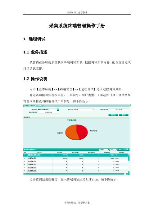
采集系统终端管理操作手册1.远程调试1.1业务描述从营销业务应用系统获取终端调试工单,根据调试工单内容,配合现场完成终端调试工作。
1.2操作说明点击【基本应用】->【终端管理】->【远程调试】进入远程调试页面。
通过该功能可实现按单位、工单编号、用户类型、工单起始日期、调试结果等查询条件查询终端调试工单信息。
如下图所示:点击查询结果超链接,进入终端调试结果明细页面,如下图所示:点击工单编号超链接,在下方展示选中终端下的表计信息;选择一条工单,点击触发调试按钮,进行终端调试页面,如下图所示:调试触发与在运系统终端调试业务基本一致,不一样的地方为调试结果页面增加了调试结果记录功能,记录终端进行那几步调试;如下图所示:选择一条工单,点击【归档】按钮,将此工单进行归档保存,仅能对调试完成的工单进行归档。
2终端参数设置2.1业务描述对终端设置终端配置参数、控制参数、限值参数等,设置的参数如下:注意:此功能页面只支持09或13规约终端进行参数设置,对于04或山东规约终端任然在终端调试功能功能菜单下操作,与在运系统业务一致。
2.2操作说明点击【基本应用】->【终端管理】->【参数管理】->【终端参数设置】进入终端参数设置页面,如下图所示:【保存召测结果】按钮为将右侧的召测值保存到数据库;【保存】按钮为将左侧的维护值保存到数据库;【保存并下发】按钮为将左侧的维护值保存到数据库并下发到终端;【按默认值下发】按钮为直接将数据库中终端的参数值直接下发到终端。
3软件升级3.1软件版本管理3.1.1终端版本召测3.1.1.1业务描述对升级程序版本进行管理;上传检测通过的厂家终端升级文件,对其升级目的、支持的原版本文件、升级后的新版本文件进行管理。
3.1.1.2操作说明点击【基本应用】->【终端管理】->【软件升级】->【软件版本管理】页面,可通过单位、终端类型、终端规约等查询条件进行查询,如下图所示:【召测】按钮实现对选中的单条终端进行召测,并将召测结果保存到数据库中;【保存全部召测结果】按钮实现对全部查询结果(限制了最多查300行的限制)进行召测,并将召测结果保存到数据库中;【按查询条件召测并保存】按钮实现对符合查询条件的全部终端进行召测,并将召测结果保存到数据库中。
WFET-1600E低压集抄集中器使用说明书(2023年)

XX工程配电箱招标技术要求及规范标准一、总体技术要求:1.投标技术条件应对本招标技术要求有文字性的响应。
2.投标人应提供IS09000系列质量体系认证证书。
3.投标人应按照设计研究院提供的配电箱(柜)的标准图纸(结构、形式)进行生产。
4.中标人所提供的产品必须保证能够通过天津市及其所属区、质检部门的各级验收。
5.投标人应具有机械工业部和电子工业部颁发的生产许可证。
6.投标人应具有中国电器工业协会会员证书。
7.投标人提供的产品应具有符合北京供电局对相关产品技术规格要求的资质证明。
8.投标人应提供设备所选用的材料(包括所选用的板材)厂家的质量体系认证证书,主要元器件必须有质量体系认证证明。
9.投标人应提供由国家电控配电设备质量监督检验中心出示的企业主要产品检验报告。
10投标人应提供所购买的元件及材料(包括开关、电线等)的中国电工产品认证委员会的安全认证书。
投标的主要元器件产品外壳上都应有长城标志或CCC标志。
11.投标人应提供企业相关产品样本。
12.投标人须明确提出设备制造、检验、试验、调试所采用的标准和规范,如与本技术要求所规定的要求出现差异时,投标人应明确所用的标准和规范,并说明其与中华人民共和国标准(GB)的差异和可靠程度。
招标人只接受等于或优于本技术要求的标准和规范。
13.招标人及本项目设计人提供的设计图纸、资料和相关信息,是本技术要求的重要组成部分,是技术要求编写和设备配置的依据,但投标人应承担对其中任何错误、遗漏和有失合理之处修正、增补、核实的全部责任。
中标方在招标方的要求下,对配电箱进行调整,只要不涉及系统的调整,均不涉及费用增加的问题。
14.招标技术文件与图纸内容是相辅相成的,二者如有矛盾,由投标方提出后以招标方的补充文字说明为准。
15.本技术要求提出的是最基本要求,投标人如对本技术要求有异议,应以书面形式明确提出,在征得招标人同意后,可对有关条文进行修改,如招标人不同意修改仍以原条文为准。
电力分布网络断路器操作说明说明书
Closed transition sequence of operationsInterlocking1. In “manual” and “automatic” mode ofoperation, main and tie breakers maynot be closed simultaneously.2. All “manual” operations of main and tiebreakers are performed using operatorinterface or breaker control switch. Whenin manual mode, control of breakers is inthe hands of the operator and no automatictransfers will occur.Lock-outOvercurrent trip switch (OTS) on main and tie breakers are incorporated in the control scheme such that there will be no closure of any breaker onto a fault. Scheme cannot be defeated andis active except during emergency operations (inoperative controls). Trip unit and OTS switch must be reset to resume automatic operations.Device definitions• 43-A device is the auto/manual switch• HMI retransfer mode is selectableon the HMI a• HMI transition is selectable on the HMI ba This feature can be a hardwired switch designated 43-1.b This feature can be a hardwired switch designated 43-2. Manual operations“Manual mode”43-A = manual, HMI retransfer = auto or manual, HMI transition = open or closedControl of breakers can be accessed through the HMI or the breaker control switch. To operate a breaker on the HMI tap the breaker you wish to operate. Automatic operation will not occur when in manual mode. However, if in closed transition and all three breakers are closed for 5 seconds (adjustable), then the tie breaker will open.Initial startup1. Place device 43-A in “manual” operation.2. Verify all transfer related circuit breakers are inthe fully-connected position in their cells.3. Open and close breakers (using operatorinterface or breaker control switch) to obtainnormal operating conditions.4. Configure settings as required on HMI.5. Place device 43-A in “automatic” operation.Normal conditions1. Main breakers 52-1 and 52-2 are closed.2. Tie breaker 52-T is open.3. Device 43-A in “automatic” position.Emergency operationIf controls are inoperative or no control power is available, all breakers may be manually operated.m CAUTIONUNDER THESE CONDITIONS, NO INTERLOCKING WILL BE ACTIVE. OPERATOR MUST NOT PARALLEL ANY SOURCES.Test modeThe system may be tested by operating in test mode on the HMI.ooee:N This is a live test, and the system will respond as if a real failure had occurred. Test function will self-cancel if a real failure should take place while testing.SettingsAll user-settable time delays are set using the timer settings page on the HMI. Delay times may be changed at any time.Eaoon1000 Eaton Boulevard Cleveland, OH 44122 United States © 2015 EatonAll Rights ReservedPrinted in USAPublication No. TD019007EN / Z17418 October 2015Eaton is a registered trademark.All other trademarks are propertyof their respective owners.Closed transition s equence of operationsTechnical Data TD019007EN Effective October 2015Sequence of automatic operations “Close transition switching”43-A = auto, HMI retransfer = auto, HMI transition = closed See normal conditions for initial configuration.A. Loss of utility power at main 52-11. Device 27/47-1 detects loss of normal voltage.2. Time delay 5 seconds (adjustable 0–60 seconds).3. Main 52-1 opens.4. Time delay 2 seconds (adjustable 0–10 seconds)then tie breaker 52-T closes.B. Loss of utility power at main 52-21. Device 27/47-2 detects loss of normal voltage.2. Time delay 5 seconds (adjustable 0–60 seconds).3. Main 52-2 opens.4. Time delay 2 seconds (adjustable 0–10 seconds),and then tie breaker 52-T closes.C. Loss of utility power at main 52-1 and 52-2No action is taken.D. Return of normal voltage to main 52-1(following sequence “A” above)1. Device 27/47-1 detects normal voltage.2. Time delay 10 seconds (adjustable 0–60 seconds).3. Device 25 verifies synchronism.4. Main 52-1 closes.5. Time delay 2 seconds(adjustable 0–10 seconds),and then tie breaker 52-T opens.E. Return of normal voltage to main 52-2(following sequence “B” above)1. Device 27/47-2 detects normal voltage.2. Time delay 10 seconds (adjustable 0–60 seconds).3. Device 25 verifies synchronism.4. Main 52-2 closes.5. Time delay 2 seconds(adjustable 0–10 seconds),and then tie breaker 52-T opens.Sequence of automatic operations “Manual re-transfer”43-A = auto, HMI retransfer = manual,HMI transition = open or closedSee normal conditions for initial configuration.ooee:N Retransfer following return of a failed source is initiated by operator. However, if second source fails, followed by return of the first-failed source, the system will transfer to the live source, and remain single-ended.A. Loss of utility power at main 52-11. Device 27/47-1 detects loss of normal voltage.2. Time delay 5 seconds (adjustable 0–60 seconds).3. Main 52-1 opens.4. Time delay 2 seconds (adjustable 0–10 seconds),and then tie breaker 52-T closes.B. Loss of utility power at main 52-21. Device 27/47-2 detects loss of normal voltage.2. Time delay 5 seconds (adjustable 0–60 seconds).3. Main 52-2 opens.4. Time delay 2 seconds (adjustable 0–10 seconds),and then tie breaker 52-T closes.C. Loss of utility power at main 52-1 and 52-2No action is taken.D. Return of normal voltage to main 52-1(following sequence “A” above)No action is taken, requires manual transfer by operator:1. Set 43-A switch to manual.2. Use breaker control switches.Or1. Navigate to one-line screen on HMI.2. Press “initiate retransfer” button on HMI screen.E. Return of normal voltage to main 52-2(following sequence “B” above)No action is taken, requires manual transfer by operator:1. Set 43-A switch to manual.2. Use breaker control switches.Or1. Navigate to one-line screen on HMI.2. Press “initiate retransfer” button on HMI screen.。
电力线宽带集抄系统安装说明
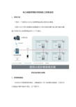
电力线宽带集抄系统施工安装说明1、系统方案:下图为一个典型的小区电力线宽带载波通讯系统的示意图。
主要分为位于单元表箱端的采集器和位于配电室侧的集中器。
集中器和采集器之间通过电力线宽带载波进行上下行通讯。
系统总体架构示意图2、系统网络建设本组网方式是根据现场情况,采集器通过485线采集电表数据,并通过电力线载波与集中器进行通讯,如下图所示:3、采集器与电能表组网方式本组网方式针对带485通讯接口的低压居民电能表环境进行组网,网络采取485总线方式进行连接,即“手拉手”方式。
如下图所示。
将485电能表A/B口分别以“手拉手”的485总线形式连接起来,最后接入采集器,完成连接。
此方式布线要满足以下要求。
1、485总线用来连接电表的485接口,电表的485端口按照电表端子盖说明进行接线。
2、485线中的红色线接入电表和采集器的485A端口,蓝色线接入到电表和采集器的485B端口,接头必须固定,不能松脱。
3、485线的安装,红色线和蓝色线之间不能短路(使用万用表检测),不能反接,也不能接触到电源。
电能表485口分为A和B两个接口,不可短路。
表箱内485线要放置规矩,并扎上扎带,保持表箱内的整洁美观。
4、宽带载波采集器4.1端口说明(本图只为参考介绍,不同批次设备的端口可能有所变化,须严格按照具体设备端盖标示的端口定义进行接线。
)宽带载波采集器端口图解端口定义描述如下:端口序号端口定义详细描述1,4L:火线N:零线供电端口,给宽带载波终端供电的电源端口,220V交流电。
5,6 P+,P- 耦合信号线端口,通过耦合器将信号注入到电力线上,采用内耦合时,此端口不用。
9,10 A,B 485信号线端口,连接电表的485输出端口或者脉冲转换器的485端口。
11,12 A,B 485信号线端口,仅供维护时使用。
4.2宽带载波采集器参数宽带载波采集器内部的采集器模块和网桥模块,两个部分的配置需要单独进行。
宽带载波采集器的采集模块参数使用手持抄表机进行设置:(1)采集器本地IP地址:采集器本身的IP地址,通过这个地址可以与采集进行通讯。
电力物联网安全防护策略手册

电力物联网安全防护策略手册第一章电力物联网概述 (3)1.1 电力物联网的定义与发展 (3)1.2 电力物联网的安全挑战 (3)第二章物理安全防护策略 (4)2.1 设备物理安全防护 (4)2.2 环境安全防护 (4)2.3 设备接入安全 (4)第三章网络安全防护策略 (5)3.1 网络架构安全设计 (5)3.2 数据传输安全 (5)3.3 网络隔离与防护 (6)第四章设备安全防护策略 (6)4.1 设备硬件安全 (6)4.2 设备软件安全 (7)4.3 设备身份认证与权限管理 (7)第五章数据安全防护策略 (7)5.1 数据加密与完整性保护 (7)5.1.1 数据加密技术概述 (7)5.1.2 对称加密技术 (8)5.1.3 非对称加密技术 (8)5.1.4 混合加密技术 (8)5.1.5 数据完整性保护 (8)5.2 数据备份与恢复 (8)5.2.1 数据备份概述 (8)5.2.2 备份策略 (8)5.2.3 数据恢复 (8)5.3 数据访问控制与审计 (8)5.3.1 数据访问控制概述 (8)5.3.2 身份认证 (9)5.3.3 访问控制列表(ACL) (9)5.3.4 数据审计 (9)第六章应用层安全防护策略 (9)6.1 应用系统安全 (9)6.2 用户身份认证与权限管理 (9)6.3 应用数据安全 (10)第七章安全监测与预警 (10)7.1 安全事件监测 (11)7.2 安全预警与应急响应 (11)7.3 安全审计与评估 (11)第八章安全管理策略 (12)8.1 安全组织与管理 (12)8.1.1 安全组织结构 (12)8.1.2 安全管理职责 (12)8.2 安全策略制定与执行 (13)8.2.1 安全策略制定 (13)8.2.2 安全策略执行 (13)8.3 安全培训与意识提升 (13)8.3.1 安全培训 (13)8.3.2 意识提升 (14)第九章法律法规与合规 (14)9.1 电力物联网相关法律法规 (14)9.1.1 法律层面 (14)9.1.2 行政法规层面 (14)9.1.3 部门规章层面 (14)9.2 合规性评估与监管 (15)9.2.1 合规性评估 (15)9.2.2 监管措施 (15)9.3 法律风险防范 (15)9.3.1 完善法律法规体系 (15)9.3.2 强化合规意识 (15)9.3.3 加强风险监控 (16)第十章技术发展趋势 (16)10.1 人工智能在电力物联网安全中的应用 (16)10.2 区块链技术与应用 (16)10.3 5G技术在电力物联网中的应用 (16)第十一章案例分析与启示 (17)11.1 国内外电力物联网安全案例 (17)11.1.1 国内案例 (17)11.1.2 国际案例 (17)11.2 案例分析与总结 (18)11.2.1 案例分析 (18)11.2.2 启示 (18)第十二章电力物联网安全防护实践 (18)12.1 电力物联网安全防护方案设计 (18)12.1.1 安全需求分析 (18)12.1.2 安全防护策略制定 (19)12.1.3 安全防护技术选型 (19)12.2 安全防护体系实施与运维 (19)12.2.1 安全防护体系实施 (19)12.2.2 安全防护体系运维 (19)12.3 安全防护效果评估与优化 (20)12.3.1 安全防护效果评估 (20)12.3.2 安全防护优化 (20)第一章电力物联网概述1.1 电力物联网的定义与发展电力物联网,是指将物联网技术与电力系统相结合,通过感知层、网络层、平台层和应用层的技术应用,实现电力系统各环节的智能化、信息化和自动化的现代电力服务系统。
电力物联网汇聚节点使用手册

汇聚节点使用说明书南京英锐祺科技有限公司二零二零年七月目录1. 汇聚节点功能特点 (1)2. 技术指标 (1)3. 硬件设备列表 (1)4. 安装所需环境 (2)5. 安装 (2)5.1 安装步骤 (2)5.2 通电前检查 (4)5.3 通电检查 (4)6. 现场需要记录的数据 (5)7. 注意事项 (5)1.汇聚节点功能特点(1)接收多种类型的周边传感器节点信息,覆盖范围大;(2)转发传感器节点信息到接入节点。
2.技术指标(1)通信频率:2.4GHz~2.5GHz;(2)天线增益:5dBi(全向);(3)辐射功率:10dbm(2.4GHz);(4)接收灵敏度:-129dBm(2.4GHz);(5)通信距离:>1000米(5db天线空旷环境中)(6)可管理节点数量:实时管理1000个;(7)工作温度:-40°C ~ +75°C;(8)功耗:<0.75W;(9)尺寸:280mm*170mm*110mm(主机);(10)供电方式:交流电AC220V;(11)封装:IP65;(12)安装方式:螺丝固定。
3.硬件设备列表中继型汇聚节点外置天线:3个470,2个2.4G六角螺母:两侧各一个固定螺丝:数个基本型汇聚节点外置天线:2个470, 1个2.4G六角螺母:两侧各一个固定螺丝:数个4.安装所需环境汇聚节点现场安装布设中需要综合考虑现场传感器和设备的分布、天线的特性、电磁波的传输特性等情况。
室内安装应该选择远离金属体、墙体、立柱等,同时要选择模块覆盖范围广、电磁波视线良好,便于安装,调试维护工作的位置。
汇聚节点可上墙式固定,也可以固定到监测柜柜顶,实际布设需综合考虑。
考虑到开关柜屏蔽效应,有可能少量微功耗长寿命传感器无法上线,所以必须就近布置基站,而传感器因为微功耗长寿命设计,发射功率小于1mw,受功耗限制无法加大发射功率,无法采用多跳MESH组网,只能通过增加基站来解决覆盖问题。
联合节点网络技术说明

遭受干扰、通信距离变短
自动愈合
无中心网络 快速路径选择
机动性好
设备体积小,便于携带 支持高速移动,最大支持350公里/小时
隐蔽性强
敌方电子侦测 “大功率”易被侦测
传统通信方式
敌方电子侦测
多跳自组网支持“微功率”接力通信、隐蔽性好
高带宽与兼容性
采用宽带调制解调技术,最大有效传输带宽可达每秒几十兆 比特,支持视频、图像、语音、数据等各种信息化应用。 全IP化的网络系统,能够兼容所有IP化的信息应用与保密手 段,能够与其他具备IP通信能力的系统(如卫星、光纤、微 波、集群等)实现互连互通。
有线
P2P对等 不依赖于后台有线交换
WiFi/Wimax/3G/光纤/ 以太网
集中式 依赖于Boss系统
2G/2.5G/2.75G
P2P对等 不依赖后台有线交换
3G
联合节点网络技术说明
无线通信网络类型
有基础设施网络
如手机网络、WiFi等。需要固定基 站、大型天线、发射塔架等基础设 施支持。网络为星型结构,基站为 中心站点,终端与终端通信需要通 过基站转发。
基站
无基础设施网络
如无线自组织网络。网络为分布式 网状结构,没有中心基站,每个网 络节点既是组网设备又是接入设备。
无线信号电平变化示例
快速路径选择
视频画面流畅不间断
技术对比2
Wi-Fi 典型应用 典型带宽 使用频率 热点 几Mbps~几十Mbps 开放频段 联合节点网络 大面积连续组网 几Mbps~几十Mbps上下 行对称 2.4G开放频段或 专用频段 3G 大面积连续组网 下行:1~3Mbps 上行:几百Kbps 专用频段 LTE 大面积连续组网 下行:100M 上行:50M 专用频段
电力物联网管理平台协议适配方案

• 40•电力物联网建设过程中,协议适配是解决存量设备接入物管平台的关键点和难点。
本文提出一种协议适配方案,高效实现协议解析、封装和数据的处理,实现设备的统一接入、管理。
2019年,国网公司启动智慧物联体系建设,国网互联网部会同设备部、营销部、物资部等部门,开展智慧物联体系总体架构设计和试点探索,取得了阶段性成果。
电力物联网管理平台协议适配方案北京中电普华信息技术有限公司 王 莹 陈渲颖 吕亚男图1 智慧物联体系如图1所示,智慧物联体系分为应用层、平台层、感知层。
物联管理平台处于平台层,部署在云平台上,是打通应用层、平台层、感知层三层之间的数据通信管道。
物联管理平台对于南向感知层的作用是负责边设备、端设备的接入,接收边、端设备上报的数据,以及对南向设备下发控制命令,对边缘物联代理进行设备管理等工作。
同时可以将设备上报的业务数据导入到数据中台,对北向业务主站开放接口,供主站通过物联管理平台读取设备的业务数据、告警信息,并下发设备的控制命令。
电力系统设备数量庞大,将这些数量众多的分散设备信息有效的收集和综合判断是智能电网必不可少的环节。
各智能设备的联系必须根据所需要交互的信息采取合适的协议,新型融合终端直接采用MQTT 协议的方式接入物联管理平台,用采、配电存量设备使用DL/T698.45、IEC104等电力专有规约,无法直接连接到物联平台中。
采用协议解析组件可以将各类设备打通,信息汇集到统一物联平台进行管理。
1 协议适配方案1.1 总体设计如图2所示,针对物联管理平台接入非MQTT 协议,研发多协议统一接入服务、协议转换模块,为电力专有L/T698.45、IEC104等协议提供通道接入服务,从而实现专有协议的数据接入。
多协议统一接入服务:基于微服务架构,实现海量终端接入的• 41•横向服务扩展,将不同业务部门的多协议接入通道统一。
协议转换模块:将各种不同的协议模式进行封装处理,对需要新配置的协议可通过系统可视化的操作方式将各参数协议配置成功,以实现智能化的协议管理。
电力物联网部署示意图、平台开发框架
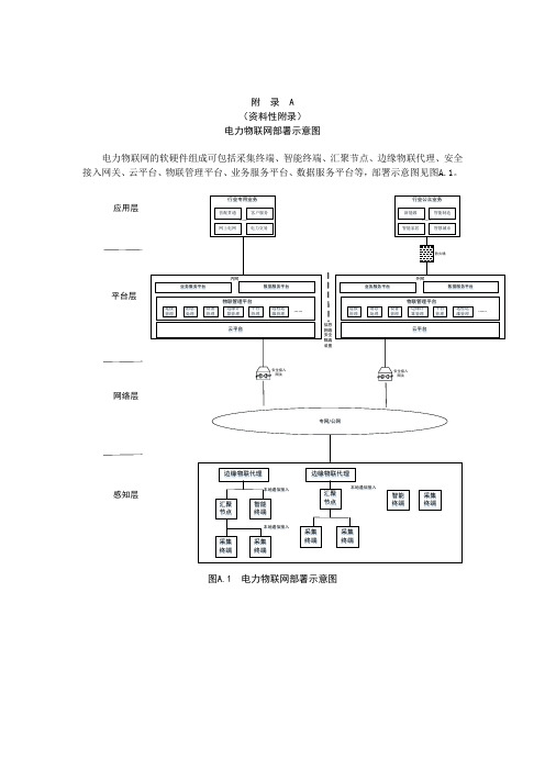
附 录 A (资料性附录) 电力物联网部署示意图电力物联网的软硬件组成可包括采集终端、智能终端、汇聚节点、边缘物联代理、安全接入网关、云平台、物联管理平台、业务服务平台、数据服务平台等,部署示意图见图A.1。
图A.1 电力物联网部署示意图内网安全接入网关专网/公网感知层网络层平台层应用层外网行业专用业务行业公众业务营配贯通客户服务网上电网电力交易新能源智能制造智能家居智慧城市…………防火墙安全接入网关云平台物联管理平台连接管理消息处理设备管理边缘计算管理平台管理远程运维管理……业务服务平台数据服务平台云平台物联管理平台连接管理消息处理设备管理边缘计算管理平台管理远程运维管理……业务服务平台数据服务平台边缘物联代理汇聚节点采集终端智能终端采集终端本地通信接入本地通信接入边缘物联代理采集终端采集终端本地通信接入汇聚节点智能终端采集终端附 录 B(资料性附录) 平台开发框架微服务是一种软件架构风格,将一个复杂应用拆分成多个服务模块,每个模块可独立编译及部署,且各模块之间可互相通信、彼此协作。
建议Paas 平台采用微服务框架,将平台功能分解到每个微服务中,从而每个功能组件都是一个可独立开发、独立运行、独立测试及独立部署的单元,见图B.1。
图B.1 平台开发框架微服务可基于Linux ,通过容器方式进行部署,微服务之间的通信宜采用与语言无关、与平台无关的轻量级通信机制,容器集群之间需要容器集群管理工具进行集群的编排、管理和维护;每个微服务可采用持续集成工具进行容器的运维和持续集成;可采用微服务注册中心实现服务发现及负载均衡。
在高并发、高实时业务场景下,Paas 平台的开发宜引入微服务消息中间件技术,保证Paas 平台的稳定性及可靠性等。
微服务架构及技术选型,见表。
表A.1 技术选型微服务容器集群轻量级通信机制(REST/RPC)轻量级通信格式(XML/JSON)容器容器微服务容器容器微服务容器微服务容器通信协议(HTTP/WebSocket)表B.1中,很多技术都是开源的,因此个人或企业在使用开源软件时,应考虑因开源许可证的规定或变动,可能面临的知识产权及合规风险、安全风险、运维和技术风险。
- 1、下载文档前请自行甄别文档内容的完整性,平台不提供额外的编辑、内容补充、找答案等附加服务。
- 2、"仅部分预览"的文档,不可在线预览部分如存在完整性等问题,可反馈申请退款(可完整预览的文档不适用该条件!)。
- 3、如文档侵犯您的权益,请联系客服反馈,我们会尽快为您处理(人工客服工作时间:9:00-18:30)。
汇聚节点使用说明书
南京英锐祺科技有限公司
二零二零年七月
目录
1. 汇聚节点功能特点 (1)
2. 技术指标 (1)
3. 硬件设备列表 (1)
4. 安装所需环境 (2)
5. 安装 (2)
5.1 安装步骤 (2)
5.2 通电前检查 (4)
5.3 通电检查 (4)
6. 现场需要记录的数据 (5)
7. 注意事项 (5)
1.汇聚节点功能特点
(1)接收多种类型的周边传感器节点信息,覆盖范围大;
(2)转发传感器节点信息到接入节点。
2.技术指标
(1)通信频率:2.4GHz~2.5GHz;
(2)天线增益:5dBi(全向);
(3)辐射功率:10dbm(2.4GHz);
(4)接收灵敏度:-129dBm(2.4GHz);
(5)通信距离:>1000米(5db天线空旷环境中)
(6)可管理节点数量:实时管理1000个;
(7)工作温度:-40°C ~ +75°C;
(8)功耗:<0.75W;
(9)尺寸:280mm*170mm*110mm(主机);
(10)供电方式:交流电AC220V;
(11)封装:IP65;
(12)安装方式:螺丝固定。
3.硬件设备列表
中继型汇聚节点
外置天线:3个470,2个2.4G
六角螺母:两侧各一个
固定螺丝:数个
基本型汇聚节点
外置天线:2个470, 1个2.4G
六角螺母:两侧各一个
固定螺丝:数个
4.安装所需环境
汇聚节点现场安装布设中需要综合考虑现场传感器和设备的分布、天线的特性、电磁波的传输特性等情况。
室内安装应该选择远离金属体、墙体、立柱等,同时要选择模块覆盖范围广、电磁波视线良好,便于安装,调试维护工作的位置。
汇聚节点可上墙式固定,也可以固定到监测柜柜顶,实际布设需综合考虑。
考虑到开关柜屏蔽效应,有可能少量微功耗长寿命传感器无法上线,所以必须就近布置基站,而传感器因为微功耗长寿命设计,发射功率小于1mw,受功耗限制无法加大发射功率,无法采用多跳MESH组网,只能通过增加基站来解决覆盖问题。
5.安装
5.1安装步骤
●测量安装高度,安装位置应在开关室检修电源箱附近墙上,离地高度约3.5
米。
●汇聚节点用六角螺母固定在支架上,整体要求简洁美观。
●安装汇聚节点天线。
●将汇聚节点通过支架固定在墙上预先留好的位置,用电钻将螺丝打入墙。
●汇聚节点接电应单独接一路电源空气开关,根据现场实际情况利用原有电源空气开关或从交流屏柜中新增一路放电缆至汇聚节点处。
●墙面处电源线开槽入墙或布放线槽,现场线槽布放应横平竖直,采用膨胀螺丝固定,电源线、放置在线槽内,现场无明线。
5.2通电前检查
(1)检查汇聚节点的机械零件、元器件是否松动、脱落,有无机械损伤,接线是否牢固;
(2)检查汇聚节点的天线是否拧紧,电源线是否插入到位。
5.3通电检查
接通电源后,按照以下步骤检查:
(1)前面板指示灯是否亮灯;
(2)亮灯后指示灯是否频繁闪烁,约0.5s/次;
(3)1分钟后指示灯1s/次闪烁为正常。
6.现场需要记录的数据
●每个汇聚节点均有一唯一编码ID号,在安装过程中,需记录好编码与安装位置对应关系(填写:《传感器安装信息表》)。
●通过安装记录表先分配好每个编号所对应的安装位置,再根据该信息表进行安装。
原则是保证记录表上信息的可靠性。
●被测位置描述:开关室、电缆层墙上(写明具体方位)。
7.注意事项
●安装人员初次安装前必须熟悉产品的各种配件和整个安装流程;
●汇聚节点应避开强电、强磁、潮湿、不通风的地点;
●汇聚节点布放电缆过程中不可以破坏原有电缆;
●汇聚节点安装后应牢固稳定,美观,不易被破坏;
●汇聚节点应保证表面清洁、光滑,无划痕及硬伤,轻拿轻放。
