ADAM-6251快速入门手册 - 免费文档
chroma63212编程手册

Chromaxxx编程手册一、概述Chromaxxx是一款先进的电子测试与测量仪器,广泛应用于电子设备制造、航空航天、通讯等领域。
为了更好地发挥Chromaxxx的功能,掌握其编程方法至关重要。
本手册将详细介绍Chromaxxx的编程接口、指令集和使用方法,帮助用户轻松实现自动化测试与数据采集。
二、编程接口介绍1. 通讯接口Chromaxxx支持多种通讯接口,包括GPIB、USB、LAN等。
用户可以根据实际需求选择合适的通讯接口,方便与PC或其他设备进行数据交互。
2. 编程语言支持Chromaxxx提供了丰富的编程语言支持,包括LabVIEW、C/C++、C#、VB等。
用户可以根据自己的熟悉程度和项目需求选择合适的编程语言,实现与Chromaxxx的无缝集成。
三、指令集介绍1. 基本指令Chromaxxx的基本指令包括初始化连接、设置参数、发送指令、接收数据等。
用户可以通过这些基本指令实现对Chromaxxx的控制和数据采集。
2. 高级指令Chromaxxx还提供了丰富的高级指令,包括自动测试程序的执行、数据分析和报告生成等。
用户可以利用这些高级指令实现更复杂的功能,提高测试效率和数据处理能力。
四、编程实例以下是一个简单的LabVIEW编程实例,演示了如何使用Chromaxxx进行电压测量:1. 初始化连接:使用GPIB接口初始化与Chromaxxx的连接;2. 设置参数:设置电压测量的范围和精度;3. 发送指令:发送测量指令给Chromaxxx,触发电压测量;4. 接收数据:接收Chromaxxx返回的电压测量结果;5. 数据显示:将测量结果显示在LabVIEW界面上,方便用户观察和分析。
五、编程注意事项1. 错误处理在编程过程中,用户应注意加入错误处理机制,及时捕获和处理Chromaxxx返回的错误信息,确保编程的稳定性和可靠性。
2. 资源释放在编程结束后,用户应注意及时释放Chromaxxx所占用的资源,包括关闭通讯接口、释放内存等,以避免资源泄漏和系统不稳定性。
str-a6252m

(Ver1.3)
6.3 控制部電氣特性
項
目
Parameter
動作開始電源電壓 動作停止電源電壓 動作時電路電流 非動作時電路電流(Vcc=12V) 平均振盪頻率 振盪頻率變動幅度 最大 ON-Duty FM 端子 High 電壓 FM 端子 Low 電壓 FM 端子流出電流 FM 端子流入電流 S/OCP 門檻(threshold)電壓 Leading edge blanking時間 自 動 間 隙 (Intermittent) 振盪門檻(threshold)電壓 OLP 門檻(threshold)電壓 OLP 流出電流 OLP 延遲時間 最大 FB 流出電流 CC Set 電壓 CC Reset 電壓 起動電流 OVP 動作電源電壓 鎖定(Latch)電路保持電流 鎖定(Latch)電路解除電壓 過熱保護動作溫度
UVLO
14 .3V/10V
⑧
1 .1mA
⑦
1 .2mA
Dra in
Dr ive
MOS FET
C .V ./C .C . Con tro l
QR S
Tmi er tFM ×128
7 .3V 7 .6V
10V 9 .6V
280 µA 310 µA
16 µA 17 µA
So f t S tar t
R QS
FB/CC/OLP terminal constant current operation control signal / over
load protection signal
電源端子
控制路電源输入
Power supply terminal Input of power supply for control circuit
快速入门指南说明书

Quick start guide for System p 550and 550Q (9133-55A)and 550(9113-550)IBM SystempRack-mounted devices are not to be used as a shelf or workspace.Do notplace any object on top of rack-mounted devices.CAUTION:The weight of this part or unit is between 32 and 55 kg (70.5 and121.2 lb.) It takes three persons to safely lift this part or unit.(C010)The exclamation mark surrounded by a gray triangle denotes caution.A CAUTIONnotice indicates the presence of a hazard that has the potential of causingmoderate or minor personal injury.Before doing a step that contains a caution icon,read and understand the caution statement that accompanies it.1Before youbeginUse safe practices when lifting.This Quick start guide contains an abbreviated set of setup instructions designed to help you quickly unpack and set up a standard system.Users unfamiliar with this IBM hardware should use the fully detailed,setup instructions that you can find in the IBM Systems Hardware Information Center.For details about how to access the information center,see task 9.Finish your system setup2.12.2Inventory Complete an inventory of the external parts.Locate the kitting report (inventory list) in the bag that contains the informationcenter CD-ROM (SK3T -8159).Make sure you received all of the parts that youordered.Y our order information should be located in an envelope adhered to theoutside of your system box.Y ou can also obtain order information from yourmarketing representative or IBM Business Partner.If you are not installing your system unit into a rack,skip to task 7.Cable theHMC and the system unit Y our IBM resellerIBM Rochester manufacturing automated information line at1-800-300-8751(United States only)Directory of worldwide contacts at /planetwide.Select your location to view the service and support contact information.2Rack-mounting hardware kitLarge retaining screws Small retaining screws Blue thumbscrews Rack-latch bracketsRack-latch bracket screwsCable-management arm bracketRack latches6822212If you have incorrect,missing,or damaged parts,consult any of the followingresources:If you are installing your system unit into a rack,you will need the following parts:3.1 3.2 3.3If you are installing your system unit into a new rack,ensure that you have completed the unpacking instructions that were provided with the rack.If your system unit is already installed in a rack,skip to taskPlace the rack in the location of the installation.Use the wrench that was provided with your rack to level the rack by raising or lowering the front and back leveling feet.Install the stabilizer bracket on the front of the rack.If necessary,remove any trim kit pieces that were previously installed on the rack.Removing the trim kit pieces allows you to read the EIA units on the rack..ABTip:7Cable the HMC and the system unit3.43Prepare the rack for installationAB4.14.2Use the rack-mounting template to determine where in therack to place the system unit.Remove any filler panelsnecessary to allow adequate access to the location whereyou will install your system.Install units into the lower part of the rack first.Placelarger and heavier units in the lower part of the rack.Follow the rack-mounting template to mark the location on therack where you will place the e the self-adhesiveplacement dots found on the rack-mounting template.Note:If you do not have enough space around your rack to open the front and back doors completely,remove the doors before starting this task to allow adequate access.Install the slide rail assemblies4Locate the rack-mounting template,the rack-mounting hardware kit,the cable-management arm,and the slide rail assemblies that were included with your system.4.4Install the slide rail assemblies .A Remove the inner slide of the slide rail by extending the slide rail,pressing theblue release button ,and fully removing the inner slide of the slide rail.B C 1.4.34.5Repeat all the steps in 4.4 for each slide rail assembly .4.Insert the front-alignment pin into the front rack flange hole as identified bythe self-adhesive placement dot.Align the back-alignment pins of the slide rail with the holes at the back of therack as identified by the self-adhesive placement dots.The back EIA position isone position higher than the front position.Ensure that the slide rails are level.Press the back latch-assembly-release tab to extend the two back-alignmentpins into the holes in the rack flange.From the back of the rack,finger tighten one of the large retaining screws intothe hole that is located between the two back-alignment pins.Repeat steps 1- 6 for the other slide rail assembly .From the front of the rack,finger tighten one of the large retaining screws intothe hole that is located above the front-alignment pin .Locate one of the latch brackets .Insert the tab at the top of the latch bracketinto the rack as shown .Attach the latch bracket to the rack with a rack-latch bracket screw ,andfinger tighten the screw in place.G D H G I J K --5.6.7.8.9.3.10.5.3Insert the inner slide of the slide rail into the slide rails mounted in the rack.D B 5.1Using the eight small retaining screws ,mount the inner slide of the slide rails to each side of the system unit,using four screws per side.Tighten the screws with a screwdriver.A B 5.25Attention:When matching the inner slide rails to the outer slide rails,ensure that both slide rail face plates glide past each other.Do not force the slide rails.If the system unit does not glide freely into the rack,completely remove the system unit from the outer slide rails,reposition the system unit,then reinsert into the outer slide rails until it glides freely into the rack.Install the system unit onto the slide rail assemblyInstall the system unit onto the slide rail assembly .CAUTION:Before installing the system unit onto the slide rail assembly,ensure that the leveling feet are extended and that the stabilizer bracket is correctly installed to prevent the rack from falling forward.Before you begin:Read this entire task before completing any individual steps.5.8Use a screwdriver to tighten the retaining screws that secure the rails to thefront rack flange.Tip:If you detect any binding,loosen the retaining screws (front and back)and repeat steps 5.5 through 5.8.5.9(Optional)transporting the rack with the systemunit installed,the rack by inserting the bluethumbscrews chassis bracket,and screwing thesystem unit to the rack flange.F 5.55.6Slide the system unit about halfway out.5.7buttons unit into the rack.E 5.46.3Use the second pin to affix the other end of the cable-management arm to thecable-management arm bracket .F A 6.1From the back of the rack,use two screws to attach the cable-management armbracket to the back left side of the system unit.B A 6.2Use one pin to affix the cable-management arm to the rack frame .F E DTip:If space is limited inside the rack,slide the system unit out part of the way to install the cable-management arm.7.17.27.3Route the power cords through the rings or clamps,if available,on theback of the server,and connect to the system unit,monitor,and HMC.Connect the mouse and keyboard cables to the appropriate ports on theback of the HMC.If your mouse and keyboard use Universal Serial Bus(USB) cables,you can connect these to the ports on the front of theHMC.Donot connect the power cords to a power source until instructed todo so.Important:Ensure that if there is a voltage switch next to the powerconnector on the monitor,it is in the appropriate position for the voltageused in your geography.7.4Attach the monitor cable to the monitor connector on the HMCand tighten the screws.A Hardware Management Console (HMC) is a system that connects to the server and manages it through a network.If you are using a rack-mounted HMC,these steps assume it is already installed in the rack.If you need to install the HMC into the rack,follow the instructions in the IBM Systems Hardware Information Center,and return to this guide when you are ready to begin cabling your HMC.For details about how to access the information center ,see task 9If you are not using an HMC to manage your server,you can use the Integrated Virtualization Manager (IVM),a graphics terminal,or an ASCII terminal.If you plan to use IVM,which allows you to create and manage partitions,skip to task 8.For information about the other console options,go to the IBM Systems Hardware Information Center.For details about how to access the information center,see task 9.Cable the system unit and access the Integrated Virtualization Manager Finish your system setup Finish your system setup.If you are using any optional adapters,connect the cables to the appropriate adapter connectors in the PCI slots of your system unit and HMC.Cable the HMC and the system unit7Tip:I f you are using the rack-mounted LCD monitor andkeyboard (7316-TF3),use the C2T -to-KVM adapterbreakout cable to attach to the HMC.7.57.6If you are not using a modem,skip to step 7.6.If you are using the integrated HMC modem,connect the telephone cable tothe modem and to the analog jack on the wall.If you are using an externalmodem,connect the modem data cable to the external modem and to a serialport on the HMC.Then connect the telephone cable to the external modemand to the analog jack on the wall.Connect the Ethernet cable to the Ethernet port on the HMC and tothe Ethernet port labeled HMC1on the system unit.7.77.87.9If using an external modem,plug the power cord into the modem.CAUTION:This product is equipped with a 3-wire (two conductors and aground) power cable and e this power cable with a properlygrounded electrical outlet to avoid electrical shock.(C018)Y ou have completed the basic setup.Skip to task 9Finish your system setup.Route the cables through the cable-management arm on the system unit and secure the cables with the straps provided.For a stand-alone HMC,use the integrated Ethernet port.For the 7310-CR2rack-mounted HMC,use the bottom-right Ethernet port.For the 7310-CR3 rack-mounted HMC,use the left port of the two planar board Ethernet ports.7.127.107.11Start and configure the HMC,which includes the Guided Setup Wizard.Y ou canfind the instructions for configuring the HMC in the Hardware Information Center.For details about how to access the information center,see task 9,.Finish yoursystem setup Press the white Power On button on the control panel.Connect the system unit to a power source and wait for the control panel on thefront of the server to display .his might take several minutes.01T Plug the power cords for the monitor,HMC,and external modem into a power source.Do not connect the system unit to a power source until instructed to do so.8.1 8.2Connect one end of a serial cable to the system port on your server,and the otherend to a serial port on a PC that has Microsoft Internet Explorer 6.0,Netscape 7.1,orOpera 7.23 installed.8Connect an Ethernet cable from the PC to the port labeled HMC1on the back ofthe system unit.If HMC1is copied,use the port labeled HMC2.If you are using any optional adapters,connect the cables to the appropriateadapter connectors in the PCI slots of your system unit and PC.Cable the system unit and access theIntegrated Virtualization ManagerCAUTION:This product is equipped with a 3-wire (two conductors and aground) power cable and e this power cable with a properlygrounded electrical outlet to avoid electrical shock.(C018)Route the power cords through the rings or clamps,if available,on the back of theserver,and connect the server to a power source.Wait for the control panel on the8.38.48.88.6At the login display appears,enter the following default passwords:In the navigation area,expand .Click .Select in the Boot to system server firmware field.Click .Power/Restart Control Power On/Off System Standby Save settings and power on User IDadmin Password admin Configure the Ethernet interface on the PC to an IP address and subnet maskwithin the same subnet as the system unit.This is the IP address for the serviceprocessor.Server connectorHMC1HMC2Subnet mask 255.255.255.0255.255.255.0IP address 192.168.2.147192.168.3.147For example,if you connected your PC to HMC1,the IP address for your serviceprocessor might be 192.168.2.1and the subnet mask would be 255.255.255.0.Setthe gateway IP address to the same IP address as that of the PC.Using a Web browser,enter the IP address into the field that correspondsto the port to which your PC is connected.For example,enter https://192.168.2.147.Address Possible values:Note :If you do not know how to do this,see the instructions in the IBM SystemsHardware Information Center.For details about how to access the informationcenter,see task 9Finish your system setup.When you are prompted,change the default password.8.78.108.91.2.3.4.Change the state of the system server firmware.8.5If this server is installed in a rack,route the cables through the cable-management arm and secure the cables to the cable-management arm.8.12Open a terminal session on the PC,using an application such asHyperT erminal.Be sure the line speed is set to 19,200 bits per second to communicate with the system unit.8.15Change the partition mode.Insert the Virtual I/O Server CD into the optical drive of the system.1.2.3.4.5.In the navigation area,expand .Click .Select in the AIX/Linux partition mode boot field.Select in the Boot to system server firmware field.Click .Power/Restart Control Power On/Off System Boot to SMS menu Running Save settings and continue system server firmware boot 8.13 1.2.3.4.In the ASMI navigation area,expand .Click .Select in the AIX/Linux partition mode boot field.Click .Power/Restart Control Power On/Off System Continue to operating system Save settings 8.14Change the partition mode back so that the server continues to load the operating system during startup.8.11After the system has reached the firmware standby state,enter the activationcode for the Virtualization Engine technologies.TM In the navigation area,expand .Click .Enter the activation key into the field.This key was included with the printedmaterial inside your system box.Click .The advanced POWER Virtualization feature is enabled.On Demand Utilities CoD Activation Continue 1.2.3.4.1.2.3.4.Select the console,and press Enter.Select a language for the BOS menus,and press Enter.Select .Select .The managed system restarts after theinstallation is complete,and the login prompt is displayed on the ASCIIterminal.Start Install Now with Default Settings Continue with Install 8.17Install the Virtual I/O Server.8.16When the system management services (SMS) menu is displayed in theterminal session over the connection that you set up in step 8.1,chooseand follow the menu options to set the optical drive asthe initial boot device.Select Boot Options Tip:Additional Information about the Virtual I/O Server,such as how to check forupdates,configure network connections,and configure partitions,is located in theIBM Hardware Information Center.Y ou have completed the basic setup.Continue to task 9Finish your system setup.Finish your system setup9Using a Web browser,go to /systems/infocenter/hardware or go tothe preinstalled version on the HMC.Answer the questions in the interactive interview,and follow the procedures in theresulting checklist.From the navigation bar,click Systems Hardware information System pinformation Initial server setup Create a customized initial server setup checklist.>>>Y ou have completed the basic tasks to set up your server.Y ou now access the .Follow these steps to create a customized checklist that you configure your server and console,install software,apply fixes,and establish connections with your service provider:can IBM Systems Hardware Information Center helps If you cannot access the online version of the information center,it is also provided on a CD with your system (SK3T -8159).9.19.29.3International Business Machines Corporation 2005,2007 Printed in USASeptember 2007All Rights ReservedMail comments to:IBM CorporationAttention Department DDR3605 Highway 52 NorthRochester,MN U.S.A.55901-7829Fax comments to:1-800-937-3430 (U.S.or Canada)1-507-253-5192 (outside the U.S.or Canada)Internet URL: /systems/infocenter/hardware References in this publication to IBM products orservices do not imply that IBM intends to makethem available in every country or region.IBM,the IBM logo and System p are trademarks and/or registered trademarks of International BusinessMachines Corporation in the United States,othercountries or both.Microsoft,Windows,Windows NT,and the Windowslogo are trademarks of Microsoft Corporation inthe United States,other countries,or both.Other company,product,and service names maybe trademarks or service marks of others.29R1711SA41-5164-04。
第2章 快速入门教程

P15第2章快速入门教程本章提要●练习1:用ArcCatalog组织数据●练习2:向地理数据库中导入数据●练习3:创建子类和属性域●练习4:创建对象间的关系●练习5:创建几何网络●练习6:为数据创建注记●练习7:为地理数据库中的数据创建层●练习8:编辑地理数据库通过数据管理工具ArcCatalog创建一个地理数据库或增加一个数据库非常容易,不需要编写任何程序就能实现。
ArcCatalog可用来浏览、储存、组织和发布数据。
在ArcMap中查询和编辑地理数据库时——ArcMap用于编辑、分析和编辑地图——不需要定制任何代码,就能充分利用地理数据库。
在教程中,利用ArcCatalog创建一个地理数据库来模拟自来水设施网络(water utility netword)。
将通过创建子类、有效性规则、关系和几何网络增加行为(behavior)到地理数据库中。
利用ArcMap编辑已有的要素和增加其它要素到地理数据库时,会体会到在地理数据库中使用行为的好处。
本教程研究的区域是位于Alabama的Montgoney市的一个部分。
这个地理数据库中包含大部分资料:表示一个自来水侧水管(water laterals)的一个Coverage,INFO表表示宗地属主(parcel owner)数据,我们需要将Coverage和INFO表导入到地理数据库中,然后修改属性以赋予其行为。
本教程通过ArcMap、ArcCatalog,掌握使用地理数据库的能力。
可以在机器上根据自己的安排而无须其它辅助完成这本教程。
本章教程包括8个练习,每个练习大约需要10-20分钟完成。
P16本章将使用多个数据集。
下面的表是对这些数据集的具体描述:要素类描述Parcels Parcel多边形Road_cl 道路中心线Road_eop 道路边线Roadnames 道路中心线注记Dimensions 度量要素Distbmains 自来水分配主水管DistmainDiam 自来水分配主水管注记Fittings 自来水网络装置Gatevalves 自来水阀门Hydrants 自来水消防栓Pipencasement 自来水管箱Prodwell1 生产井1Prodwell2 生产井1Pumpstat 泵站Sysvalves 自来水系统阀Tanks 自来水箱Transmains 传输主水管transmainsdiam 传输主水管注记trtplant 自来水处理厂vaults 自来水表拱顶P17本教程中的数据由Alabama的Montgoney市水厂和污水公司提供,ESRI公司把这些数据简单化。
海泰克
貳.软件操作及练习前言:为了协助您很快的了解ADP3的规划操作,本章将详细介绍常用画面组成组件的基本范例,及几种典型组件的设计操作方法让初学者很快地就可以完成实际的画面编辑工作,并且逐步说明实际和P.L.C.联机之执行步骤及相关参数设定注意事项;并可立即和PLC联机操作。
而相关组件进阶应用之设计说明请洽各区经销商的人机应用课程介绍。
※本章说明乃针对PLC厂牌为S7-200 CPU214机型。
练习1、开启应用档1). 方法一:在档案栏的下拉窗体中选开新档案。
方法二:鼠标直接点取功能按钮行之开新档案图式按钮。
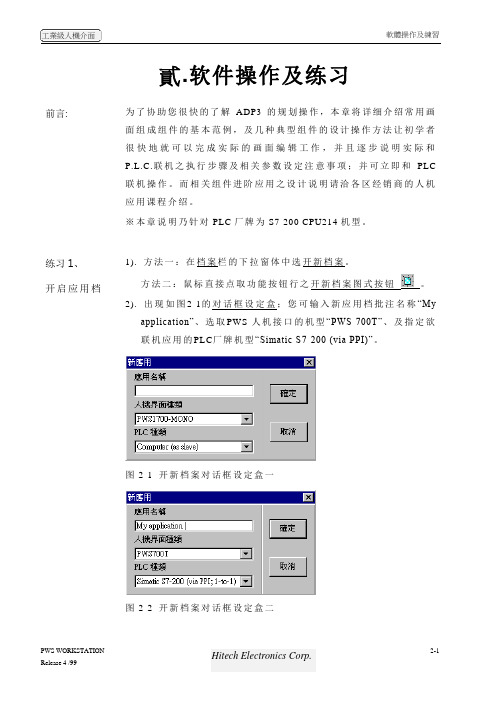
2). 出现如图2-1的对话框设定盒;您可输入新应用档批注名称“Myapplication”、选取PWS-人机接口的机型“PWS-700T”、及指定欲联机应用的PLC厂牌机型“Simatic S7-200 (via PPI)”。
图2-1 开新档案对话框设定盒一图2-2 开新档案对话框设定盒二3、当新应用文件被开启后,屏幕会出现图2-3 ADP3画面层程序窗口。
图2-3 ADP3程序窗口_应用文件层窗口练习2、认识画面组件可对应的PLC资料地址在ADP3开始规划画面组件前,设计者必须清楚了解可以使用的PLC资料地址的格式及范围;在ADP3软件中大部份均依照PLC本身原厂格式,所以您可以参考PLC原厂技术手册;下表所列为针对SIEMENS S7-200 CPU216:表1. 在ADP3软件规划可以使用的P.L.C.缓存器地址的格式及范围缓存器种类代号格式编号范围资料长度Remark Input Image IWn n=0-6 WordInput Image IDn n=0-4 Double WordOutput Image QWn n=0-6 WordOutput Image QDn n=0-4 Double WordInternal Bits MWnn nn=0-30 WordInternal Bits MDnn nn=0-28 Double WordSpecial Bits SMWnnn nnn=0-27 Word Read only Special Bits SMWnnn nnn=28-192 WordSpecial Bits SMDnnn nnn=28-190 Double WordData Area VWnnnn nnnn=0-5118 WordData Area VDnnnn nnnn=0-5116 Double WordSpecial S SWnn nn=0-30 WordSpecial S SDnn nn=0-28 Double WordTimer Tnnn nnn=0-255 WordCounter Cnnn nnn=0-255 WordAnalog input word AIWnn nn=0-30 Word Read only Analog output word AQWnn nn=0-30 Word Read only功能圖式按鈕行開新檔案圖式按鈕標題行存檔圖式按鈕開新畫面圖式按鈕呼叫畫面圖式按鈕呼叫舊檔圖式按鈕注意1:CPU-212 不能使用AIW, AQW, SW, SD注意2:PLC缓存器地址的范围须受限于P.L.C主机CPU的机型,应用时,请限制不可超过该CPU本身的最大值,否则会通讯失败。
NI 6251 M系列数据采集器产品规范说明书

产品规范NI 6251M系列数据采集:16 AI、1.25 MS/s、24 DIO、2 AO除非另外声明,否则下列规范的适用温度均为25 °C。
关于NI 6251的详细信息,请参考/manuals上的M Series User Manual。
模拟输入通道数8个差分或16个单端ADC分辨率16位DNL保证无丢失代码INL请参考AI绝对精度采样率单通道最大值 1.25 MS/s多通道最大值(多路综合) 1.00 MS/s最小值无最小值定时分辨率50 ns定时精度采样率的50 ppm输入耦合DC输入范围±0.1 V、±0.2 V、±0.5 V、±1 V、±2 V、±5 V、±10 V±11 V,AI GND模拟输入的最大工作电压(信号+共模)CMRR(DC至60 Hz)100 dB输入阻抗设备开启AI+对AI GND>10 GΩ,与100 pF电容并联AI-对AI GND>10 GΩ,与100 pF电容并联设备关闭AI+对AI GND820 ΩAI-对AI GND820 Ω输入偏置电流±100 pA串扰(100 kHz)相邻通道-75 dB非相邻通道-95 dB小信号带宽(-3 dB) 1.7 MHz输入FIFO容量4,095个采样扫描列表内存4,095项数据传输PCI/PCI Express/PXI/PXI Express DMA(分散-收集)、中断、编程控制I/O USB USB信号流、编程控制I/O所有模拟输入和SENSE通道的过压保护设备开启±25 V,最多4个AI引脚设备关闭±15 V,最多4个AI引脚过压时的输入电流±20 mA/AI引脚,最大值多通道测量的稳定时间表1.多通道测量的稳定时间2||NI 6251产品规范典型特性图图 1. 稳定误差和不同源阻抗时间的关系时间 (µs)误差(跳变大小的p p m )图 2. AI 小信号带宽–8–7–6–5–4–3–2–1011 k10 k100 k 1000 k10000 k频率 (Hz)归一化信号幅值 (d B )NI 6251产品规范 | © National Instruments | 3图3. AI CMRR频率 (Hz)CMRR(dB)AI绝对精度注:自设备外部校准起,表中给出精度的有效期为两年。
ADAM-6000快速入门手册

ADAM-6000快速入门手册一、ADAM-6000概述ADAM-6000智能型Ethernet I/O模块是基于以太网远程数据采集模块,提供摸拟量输入及输出、数字量输入及输出、继电器输出及计数器/定时模. 独特的最佳化I/O 群组设计,使ADAM-6000系列智能型模块成为可利用Ethernet达成数据撷取及控制的产品。
ADAM-6000系列的设计为工业自动化I/O系统带来变革性发展。
ADAM-6000系列特点:1. 工业以太网络(Industrial Ethernet)通讯基准: ADAM-6000模块支持TCP/IP及UDP over 10/100 Mbps Ethernet networks. 支持Modbus协议。
2 . 智能型运算逻辑: ADAM-6000系列提供内建控制运算逻辑与数学程序,以立即执行现场控制策略,简化中央监控主机之运算负荷。
3. 简易型HMI浏览器: ADAM-6000系列不仅提供标准网页监控接口,也同时具备客制化监控网页编辑功能。
因特网的普及,让客户可以轻易的从企业端、家庭里或便携式计算机,随时随地的浏览现场制程状况。
4. 最佳化I/O群组设计: ADAM-6000的最佳化I/O群组是根据应用导向的概念来设计,一对一的搭配使用(I/O模块对监控设备),可让I/O系统的应用达到最佳化,同时减少工程和维护成本。
ADAM-6000小型网络I/O模块是一款在工业自动化环境下,以太网网络工作解决方法的工业级以太网集线器/开关.它允许用户快速有效的扩展他们的工业网络。
ADAM-6000可以通过ADAM-5000TCP-6000 Utility对其进行配置和测试,提供DLL函数库供用户编程调用,提供Modbus OPC Server用于和其它软件进行整合。
二、智能 Web I/O 模块(ADAM-6000)ADAM-6050 18路隔离数字量I/O模块ADAM-6051 16路带计数器的隔离数字量I/O模块ADAM-6052 16路源点型数字量I/O模块ADAM-6060 6路DI/6路继电器模块ADAM-6066 6路DI/6路功率继电器模块ADAM-6015 7路热电阻模块ADAM-6017 8路带DO的模拟量输入模块ADAM-6018 8路带DO的热电偶输入模块ADAM-6024 12路通用输入/输出模块ADAM-6022 基于以太网的双回路PID控制器三、 ADAM-6000硬件连接1.电源连接:2.网络连接:用RJ-45连接器连接ADAM-6000的连接器到通过直连网线连接到HUB上,最大的通信长度支持10M和100M网速。
Paramics快速入门手册

Paramics快速入门手册本手册旨在提高广大用户的基础应用能力,为广大用户入门提供参考,手册涵盖了软件的安装与运行、仿真路网状态的查看、数据报告的查看和三维仿真方面的基础操作等内容。
用户可以以本手册作为学习Paramics软件的辅助手册,结合软件其他的技术操作手册(软件自带的manual)进行Paramics软件的基础学习。
用户在使用本手册的过程中如有疑问,请跟我们技术支持部门联系,发邮件至Paramics-China@, 或登陆我们的网站,九州联宇将给您提供完善的技术支持服务。
第一章 安装、运行软件 (3)1.1安装软件 (3)1.2运行软件 (3)第二章 使用Paramics软件 (4)2.1、二维模式下 (4)2.2、三维模式下 (4)2.3、观察点控制 (4)2.4、地图窗口 (6)2.5、仿真控制操作 (6)第三章 仿真分析 (7)3.1、OD显示 (7)3.2、热点显示 (8)3.3、车辆动态信息显示 (9)3.4、车辆追踪 (11)3.5、公共交通信息显示 (12)第四章数据报告 (13)第五章演示 (14)5.1、设置图层 (14)5.2、图层叠加 (14)5.3、PMX模型 (15)5.4、环境影响因素 (16)5.5、飞越播放 (17)第六章制作仿真视频 (18)结语 (19)第一章 安装、运行软件1.1安装软件用户在安装Paramics V6安装之前,必须确认安装了.NET Framework 3.0以上的版本。
确认安装之后按照以下步骤操作:1、插入安装光盘,以下两部分是必不可少的,点击Paramics V6 setup,运行软件2、按照屏幕出现的安装指南进行操作3、安装结束后要重启计算机1.2运行软件用户在启动Paramics之前,确保USB软件狗的红灯闪亮用户可以通过一下操作打开Paramics路网点击开始菜单,打开Paramics建模器(Modeller);在软件中点击File ――Open,打开存放路网文件的文件夹;选中Demo1,点击OK即可载入演示网络。
- 1、下载文档前请自行甄别文档内容的完整性,平台不提供额外的编辑、内容补充、找答案等附加服务。
- 2、"仅部分预览"的文档,不可在线预览部分如存在完整性等问题,可反馈申请退款(可完整预览的文档不适用该条件!)。
- 3、如文档侵犯您的权益,请联系客服反馈,我们会尽快为您处理(人工客服工作时间:9:00-18:30)。
免费文档中心免费文档中心可免积分在线阅读和下载文档∙免费文档∙高等教育∙高中教育∙初中教育∙小学教育∙外语考试∙资格考试∙工作范文∙求职职场∙党团工作∙表格模板∙总结汇报∙经管营销∙工程科技您的位置:免费文档所有分类工程科技信息与通信 ADAM-6251快速入门手册ADAM-6251快速入门手册Adam-6251 快速入门手册 ADAMADAM-6251 快速入门手册第一章产品介绍 .................................................................. ............................................................ 2 1.1 Adam-6200 概述................................................................... ......................................................... 2 1.2 Adam-6251 概述................................................................... ......................................................... 4 1.3 规格说明 .................................................................. ......................................................................4 1.3.1 一般规格 .................................................................. ............................................................. 4 1.3.2环境 .................................................................. .....................................................................5 1.3.3 Adam-6200 系列私有特性 .................................................................. ................................ 5 1.3.4 数字量输入参数 .................................................................. ................................................. 5 第二章 Adam 的软件安装................................................................... ............................................. 6 2.1 初始检查 .................................................................. ....................................................................6 2.2 安装 Advantech Adam/Utility ............................................................. ..................... 6 2.2.1 软件下载路径 .................................................................. ....................................................... 6 2.2.2 软件支持的操作系统 .................................................................. ........................................... 6 2.2.3 安装 Advantech Adam/Utility ............................................................. ................. 6 第三章硬件连接及测试 .................................................................. ................................................ 9 3.1 硬件连接 .................................................................. ......................................................................9 3.1.1 电源连接................................................................... ............................................................ 9 3.1.2 硬件接线................................................................... ............................................................ 9 3.1.3 Adam-6251 数字量输入功能接线 .................................................................. ................... 11 3.2 Adam-6251 的 Modbus TCP 通信协议编程时的地址映射....................................................... 13 3.3 软件测试 .................................................................. .................................................................... 15 3.3.1 Adam 模块通用参数配置 .................................................................. .................................. 15 3.3.2 Adam-6251 模块功能测试................................................................... ................................ 21 (1)数字量输入功能概述 .................................................................. ...................................... 22 (2) DI 通道高级功能设置 .................................................................. ..................................... 24 3.3.3 Adam-6251 GCL 功能 .................................................................. ...................................... 27 第四章例程使用详解 .................................................................. .................................................... 27 4.1 Adam-6251 板卡支持例程列表 .................................................................. ................................ 28 4.2 常用例子使用说明(以 CSharp 例程为例) ................................................................ .............. 28 4.2.1 Adam62XXDIO(数字量输入输出状态瞬时读值) ...................................................... 28 4.2.2 DataStreaming(主动定时上传功能,监测数据流信息) ............................................. 29 4.2.3P2P_UdpEvent(点对点功能和事件触发)..................................................................... 30 第五章遇到问题,如何解决? ................................................................ .................................... 32 1页下一页文档免费下载:ADAM-6251快速入门手册(共32页,当前第1页)你可能喜欢∙快速入门手册∙使用手册∙技术手册∙客户手册∙用户手册∙评价手册∙实施手册∙计价手册∙F2MC-16 SOFTUNE V3 快速入门手册73页∙lingo8.0中文快速入门手册53页∙M218 快速入门手册_V1.2_2010060841页∙TKSA40快速入门手册2页∙通达OA工作流程案例及快速入门手册135页∙会议快速入门手册(浦口区行政服务中心)4页更多与“快速入门手册”相关的内容>>∙DH-DRS录音系统使用手册16页∙OA操作使用手册[1]10页∙电子环使用手册3页∙老板无忧监控管理软件-使用手册26页∙ASA301硬件使用手册10页∙PriciseProject使用手册219页更多与“使用手册”相关的内容>>∙YF17技术手册63页∙R434a技术手册10页∙弯头技术手册24页∙SPE技术手册82页∙项目技术管理手册9页∙A4900A技术手册2页更多与“技术手册”相关的内容>>∙2012年集团客户营销产品手册32页∙装饰管客户服务流程手册18页∙大客户流程手册175页∙客户沟通手册4页∙400终端客户操作手册41页∙金牌客户服务人员手册07072565页更多与“客户手册”相关的内容>>∙PM-300用户手册159页∙TRSWCMV6用户安装手册(标准版)46页∙STM32F103-EVAL+用户手册38页∙CmailPlus用户手册18页∙出纳机用户手册5页∙企业用户操作手册50页更多与“用户手册”相关的内容>>∙英语评价手册(1-6Vocabulaary2011-12)7A30页∙附1嵘昌集团评价手册42页∙扎旗音三中课堂教学评价手册3页∙绩效评价应用手册26页∙评价手册参考11页∙教育教学实践评价手册34页更多与“评价手册”相关的内容>>∙课题管理与实施手册9页∙san实施手册58页∙5S实施手册21页∙erp实施手册73页∙Vmware_vsphere 实施手册48页∙课题实施手册27页更多与“实施手册”相关的内容>>∙计价手册办理程序2页∙计价手册申请范本6页∙《计价手册》登记表3页∙浙江03计价培训手册39页∙《模具计价手册》简介1页∙建设工程计价手册年检认证表6页更多与“计价手册”相关的内容>>ADAM 6251快速入门手册的相关文档搜索∙win10快速入门手册∙起亚k2快速入门手册∙thinkphp快速入门手册∙起亚k5快速入门手册∙起亚k3快速入门手册∙拍立得快速入门手册∙tiny快速入门手册∙adam4000手册ADAM 6251快速入门手册相关文档∙ADAM-6052快速入门手册38 1 Adam-6052 快速入门手册第一章产品介绍 1.1 adamadam-6052概述Adam-6052 是一款基于以太网远程数据采集的智能型 I/O 模块。