基于LSM303DLH集成传感器的电子罗盘实现方法
电子罗盘调研
电子罗盘调研2014-02-211 电子罗盘功能介绍1.1 名字解释电子罗盘,也叫数字指南针,是利用地磁场来定北极的一种方法。
古代称为罗经,现代利用先进加工工艺生产的磁阻传感器为罗盘的数字化提供了有力的帮助。
现在一般有用磁阻传感器和磁通门加工而成的电子罗盘。
电子罗盘具有以下特点:●三轴磁阻效应传感器测量平面地磁场,双轴倾角补偿。
●高速高精度A/D转换。
●内置温度补偿,最大限度减少倾斜角和指向角的温度漂移。
●内置微处理器计算传感器与磁北夹角。
●具有简单有效的用户标校指令。
●具有指向零点修正功能。
1.2 电子罗盘作用1.2.1 GPS导航定位的缺陷1) 虽然GPS在导航、定位、测速、定向方面有着广泛的应用,但由于其信号常被地形、地物遮挡,导致精度大大降低, 其信号可用性仅为60% ,甚至不能使用。
产生不精确定位的原因包括:①多路径效应:建筑物对GPS信号的反射②阴影:城市中高楼与高楼之间形成的“峡谷”内、浓密的植被下,信号接收效果较差③在隧道、地下停车厂造成的信号失锁④在接收信号差的地区延长了初始化时间⑤一些动态影响,如汽车大幅度增速与减速等。
以上原因都会导致GPS无法提供任何位置或者定位精度陡然下降。
2) 在静止的情况下,GPS也无法给出航向信息。
高精度电子罗盘可以对GPS信号进行有效补偿,保证导航定向信息100%有效,即使是在GPS信号失锁后也能正常工作,做到“丢星不丢向”。
3) 安全及可靠性风险。
美国出于自身利益上的考虑,从不承诺不实施SA干扰和区域关闭,这更给GPS用户带来很大疑惑和担心。
因此,将GPS与电子罗盘相结合,二者相互补充,组合使用是导航领域的理想选择。
例如:美国虽然其完全独立掌握GPS 的卫星资源,但为了使系统更加可靠,使导航信息100%有效,其M1坦克及其它一些重要装备上仍加装了C100电子罗盘。
1.2.2 电子罗盘主要用途电子罗盘主要用于辅助GPS导航及在静止状态获取航向,具体包括加速度和方向的定位、倾角测量等功能。
基于电子罗盘的方向传感器系统设计

基于电子罗盘的方向传感器系统设计一、引言随着科技的不断发展和应用范围的不断拓展,传感器的应用已经渗透到了我们日常生活的方方面面。
其中,方向传感器系统作为一种不可或缺的设备,已经得到了广泛的应用。
在本文中,我们将会针对基于电子罗盘的方向传感器系统进行设计和探讨。
二、方向传感器系统的基本原理方向传感器通常是一种基于电子技术的系统,它可以用来检测和记录一个物体(如汽车、飞机或船舶)的方向。
而其原理主要是基于磁力传感器的工作方式。
磁力传感器利用磁场来检测物体的方向,这些磁场通常是由地球的自然磁场所产生的,也可以是由外部磁体产生的。
在这种情况下,我们需要采用电子罗盘作为磁力传感器,以确保方向传感器系统具有高精度和高可靠性。
电子罗盘是一种电子设备,可以通过感应地球磁场的变化来测量真实的方向。
三、基于电子罗盘的方向传感器系统的设计基于电子罗盘的方向传感器系统是一种重要的辅助导航设备,通常应用于航空、航海、轨道交通等领域。
因此,该系统的设计需要充分考虑其应用环境和场景,以确保其满足工程应用的要求。
1. 硬件设计基于电子罗盘的方向传感器系统的硬件设计包括传感器、模拟部分和数字部分。
(1)传感器该系统的传感器通常应为硬铁置于电子罗盘板上的八方向3轴磁场传感器。
八方向表面是一个晶圆盘,罗盘板上的硬铁从纵向和横向的8个方向上紧密环绕。
3轴磁场传感器可检测物体沿X、Y和Z轴方向的磁场变化,这是漂移抑制的关键。
(2)模拟部分模拟部分主要是用来对传感器的输出进行放大、滤波和A/D转化等处理。
由于系统的精度和稳定性直接取决于该部分的设计,因此在进行模拟部分的设计时需要充分考虑其系统电源选择、运放选择、滤波器电容和放大倍数等因素。
(3)数字部分数字部分是基于单片机的编程处理,主要用来完成接收、转换和显示数据。
该部分的设计需要考虑系统设计的应用和性能要求,以确保其能够满足不同应用场景的需求,并实现高速响应、低能耗和实时数据传输。
2. 软件设计基于电子罗盘的方向传感器系统的软件设计主要包括算法设计和界面设计。
《传感器与自动检测技术(第4版)》教学教案(模块7)
【图示】记忆合金曲别针;自适应巡航
概念讲演法
概念讲演法
图示展演法
概念讲演法
图示展演法
概念讲演法
列表归纳法
图示展演法
案例分析
【应用案例】二维自适应图像智能传感器
由上述内容可知,智能传感器是“电五官”与“微电脑”的有机结合,对外界信息具有检测、判断、自诊断、数据处理和自适应能力的集成一体化的多功能传感器。
2.微结构(智能结构)是今后智能传感器重要发展方向之一。
3.利用生物工艺和纳米技术研制传感器功能材料,以此技术为基础研制分子和原子生物传感器是一门新兴学科,是21世纪的超前技术。
4.完善智能器件原理和智能材料的设计方法,也将是今后几十年极其重要的课题。
【图示】ABS的防侧翻稳定控制系统(RSC);西门子智能视觉传感器。
【图示】二维自适应图像智能传感器;三维多功能单片智能传感器。
【图示】精密智能压力变送器;A2彩色平板环保扫描仪;智能血糖仪;汽车电池监控智能传感器;奥地利medel公司中耳植入振动声桥
案例教学法
图示展演法
图示讲演法
图示展演法
概念分析
三、智能传感器的发展前景
1.利用微电子学,使传感器和微处理器结合在一起实现各种功能的单片智能传感器,仍然是智能传感器的主要发展方向之一。
【图示】智能手机电子指南针
【图示】LSM303DLH传感器模块结构示意图
电子指南针集成了三轴磁力传感器和三轴加速度传感器,分别用于检测磁场数据和航向倾角,如LSM303DLH传感器模块。
案例教学法
图示展演法
图示讲演法
作业
教材认知训练7-1、7-2
练习巩固法
本课教育评注(课堂设计理念,实际教学效果及改进设想)
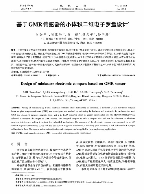
基于GMR传感器的小体积二维电子罗盘设计
第2 卷第6 9 期
21年6 02 月
机
电
工
程
Vo .2 o6 1 9 N .
Ju n lo c a ia o ra fMe h nc l& E e tc lEn ie r g lcr a gn ei i n
Jn 0 2 u .2 1
基于 G MR传 感器 的小体 积二维 电子罗盘设计水
环境 中 , 通过旋转校 准 , 然可 以保证较 高的精度 。同时 , 依 将校准数据 I P A 到单 片机 Fah中 , l s 即使 系统掉 电也可 以保证数据不 丢 失 。经 国防科技工业弱磁一级计量站的测试 , 其测试结果表 明, 该设 备在无 干扰情况下精度可达± 。 在强 干扰下精度依然较高 , 2, 具 有较强的工程实用价值 。 关键词 :G MR传感 器 ; 二维罗盘 ; 抗干扰
时劭 华 , 正 洪 , 茹 , 天 平 , 宇 澄 。 钱 白 龚 孙
(. 1 杭州 电子科技 大学 磁 电子 中心 ,浙 江 杭州 30 1 ; 10 8 2 东 方微磁科 技有 限责任公 司 ,湖北 宜 昌 4 30 ) . 4 0 3
摘要 : 针对二维 电子 罗盘存在 的体积 、 精度较难平衡等问题 , 对二维 电子罗盘展开 了研究 。通过对硬件与算法的优 化设计 , 出了 提
基于单片机的二维电子罗盘设计

基于单片机的二维电子罗盘设计
孙军亮
【期刊名称】《信息与电脑》
【年(卷),期】2022(34)3
【摘要】随着科技的快速发展,电子罗盘逐渐替代传统的导航定向工具指南针,在组合导航、航海航天、航海测绘以及飞行器控制等领域得到了广泛的应用。
电子罗盘是一种利用地磁场实现方位角测量的定向导航仪器,在各种导航技术蓬勃发展的背景下,电子罗盘产品以其独有的优良特性在导航定向方面仍被作为基本的工具广泛使用。
基于这一背景,笔者以专用的磁场传感器为基础来建立测量磁场的新方法。
通过SPI总线与磁传感器驱动芯片进行通信,完成磁场参数的采集,并利用软件编程对其进行精度处理,再显示出方向角。
基于单片机的二维电子罗盘实现了对磁场参数的采集、校正处理以及显示,精度和灵敏度较高且扩展性较强,可用于普通导航领域。
【总页数】4页(P17-20)
【作者】孙军亮
【作者单位】陕西陕煤韩城矿业有限公司
【正文语种】中文
【中图分类】TP212.9
【相关文献】
1.基于GMR传感器的小体积二维电子罗盘设计
2.基于STC单片机的电子罗盘-超声波测障系统设计
3.基于磁阻传感器的二维电子罗盘设计
4.基于GMR传感器的车载二维电子罗盘设计
5.基于磁阻传感器与微处理器的二维磁电子罗盘的设计
因版权原因,仅展示原文概要,查看原文内容请购买。
基于MEMS传感器的高精度电子罗盘研究

基于MEMS传感器的高精度电子罗盘研究葛海浪;佘勃;陶迁【摘要】针对电子罗盘易受到干扰和成本高等问题,对电子罗盘结构、倾角补偿、误差分析、误差校正等方面进行了研究,对电子罗盘在实际应用中的误差来源和校正算法进行了归纳,提出了基于STM32 ARM Cortex-M3内核单片机以及MEMS 传感器构建电子罗盘系统,开展了电子罗盘的误差分析,提出了电子罗盘误差模型,提出用卡尔曼滤波算法对磁阻传感器和加速度计进行了数据融合与滤波,在利用加速度计计算倾角的基础上对电子罗盘进行了倾角补偿,利用Matlab处理上位机采集到的电子罗盘数据,进行了电子罗盘的输出角度和精度试验.研究结果表明,该电子罗盘可获得高精度的静态姿态角.【期刊名称】《机电工程》【年(卷),期】2016(033)003【总页数】4页(P276-279)【关键词】微机电系统;磁阻传感器;电子罗盘;加速度计【作者】葛海浪;佘勃;陶迁【作者单位】宿迁学院机电工程学院,江苏宿迁223800;宿迁学院机电工程学院,江苏宿迁223800;宿迁学院机电工程学院,江苏宿迁223800【正文语种】中文【中图分类】TH7在机器人、航海和航空航天等领域中,都需要导航系统为其导航,导航系统中最重要的就是航向的获得,而传统的罗盘具有体积大、结构复杂、安装不便等诸多缺点,使传统的惯性导航系统无法得到广泛应用。
而随着微机电系统(MEMS)技术的快速发展,MEMS器件的制造工艺不断成熟,使MEMS传感器的制造成本不断降低。
基于MEMS传感器设计的电子罗盘具有高精度、低成本、结构简单等特点,因此其被广泛应用于军用民用领域[1]。
利用MEMS三轴加速度计SCA3100和三轴磁阻传感器HMC5883L,本研究以单片机STM32作为主控芯片构建电子罗盘[2],,提出用卡尔曼滤波算法对磁阻传感器和加速度计进行数据融合与滤波,构建电子罗盘误差模型,在倾角补偿的基础上以获得较高的航向精度。
基于MEMS传感器的可校准电子罗盘实验设计

基于MEMS传感器的可校准电子罗盘实验设计
应亚萍;王洁;倪佳乐;张逸宁;徐浩东
【期刊名称】《通信电源技术》
【年(卷),期】2022(39)21
【摘要】大多数的导航系统都使用电子罗盘,但电子罗盘的输出易受外界磁场干扰,需要进行校准后才能得到准确的航向角。
设计了一种基于微电机系统(Micro Electro Mechaical System,MEMS)传感器的可被校准补偿的三维电子罗盘,介绍
了电子罗盘的工作原理,推导出姿态角计算公式,分析了电子罗盘的罗差来源以及应
用基于椭圆拟合的补偿方法来校准罗差。
该电子罗盘具有体积小、功耗低、成本低、方法简单快速等特点,对未来要求小、体积高精度的电子罗盘设计具有参考价值。
【总页数】5页(P33-37)
【作者】应亚萍;王洁;倪佳乐;张逸宁;徐浩东
【作者单位】浙江工业大学之江学院
【正文语种】中文
【中图分类】TP2
【相关文献】
1.基于MEMS传感器的高精度电子罗盘研究
2.基于MEMS传感器的微小型三维
电子罗盘设计3.基于磁阻和MEMS加速度传感器的电子罗盘设计及应用4.基于MEMS传感器的电子罗盘设计5.基于磁感式和MEMS加速度传感器的电子罗盘设计
因版权原因,仅展示原文概要,查看原文内容请购买。
电子罗盘

哈尔滨理工大学开放实验报告实验项目名称:电子罗盘系统的原理与设计学生所在学院:测控技术与通信工程学院学生所在班级:学生姓名:实验总学时数:指导教师:哈尔滨理工大学教务处制20 年月日一、实验目的与任务:实验目的:通过对《电子罗盘系统的原理与设计》总体认识,学习电子罗盘的原理及涉及的相关知识,运用加速度计和磁阻传感器以MSP430单片机为核心处理器,1602为显示机构,完成电子罗盘的设计。
在完成设计的同时,对自身能力的提高,在科学技术飞速发展的社会里,增加自己的社会竞争力。
实验任务:1. 查阅资料在对电子罗盘原理的有一定了解的基础上,确定完成实验所需要的元器件2.设计电子罗盘的硬件系统并作出原理图。
3.对部分可仿真电路进行仿真,修改原理图。
4.学习Protel软件绘制PCB板,并绘制出PCB图。
5.掌握贴片电阻的焊接技术,焊接电路板,进行调试。
6.学习并掌握MSP430单片机上编程资源及相关的使用方法,在IAR软件开发环境上编制主程序及各部分子程序;完成磁阻电子罗盘的软硬件联合调试,实现系统功能。
7.开发开发板的其他功能。
二、实验前的准备工作(包括资料查找、相关知识准备等):1.查阅资料初步了解电子罗盘的原理,初步学习430正确选用试验中所需要的芯片,对电子罗盘的设计有整体的结构框架并设计出实验方案。
把实验方案交指导教师,根据指导教师建议对实验方案的可行性、实验室条件等因素对方案进行完善修正,使之具有可操作性,满足实验目的要求,确定实验方案并制定实验进度计划。
2. 分析磁阻效应从而了解磁阻传感器的工作原理及其输出信号特征,进而明确磁阻电子罗盘利用地球磁场测量载体方向的原理。
3. 根据实验进度依次完成各进度中所需知识的学习。
(1) 学会用Protel绘制电路板,并完成MSP430最小系统及传感器模块的原理图和PCB图的绘制。
(2) 加工印制电路板并完成焊接。
(3) 学习MSP430单片机原理,完成最小系统板的硬件调试。
基于GMR传感器的三轴电子罗盘
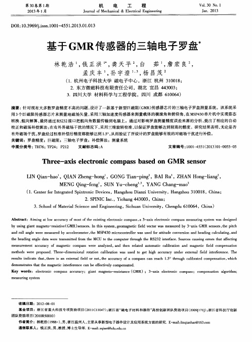
ME N G Q i n g — f e n g ,S U N Y u — c h e n g , YA N G C h a n g — ma o
用3 个 巨磁阻传感 器芯片来测量地磁场矢量 , 采用三轴加 速度传感器来测量载体 的横滚 角和俯仰 角 , 在 MS P 4 3 0 单片机 中实现姿态
转换 、 航 向解算 。 最终通过 R S 2 3 2 接 口把航 向角数据传输到 电脑上 。通过对影 响罗盘测 量精度误差来源的分析 , 提 出了相应 的 自动
D OI : 1 0 . 3 9 6 9 0 . i s s n . 1 0 0 1 — 4 5 5 1 . 2 0 1 3 . 0 1 . 0 1 3
基于 GMR传感器的三轴 电子罗盘
林 乾 浩 , 钱 正 洪 , 龚 天 平 , 白 茹 , 詹宏 良 , 孟庆 丰 , 孙 宇 澄 , 杨 昌茂
中 图分 类 号 : T H 7 6 ; T P 2 4 ;P 2 1 2 文献标志码 : A 文章 编 号 : 1 0 0 1 — 4 5 5 1 ( 2 0 1 3 ) 0 1 - 0 0 5 5 - 0 5
Th r e e ‘ _ 。 a x i s e l e c t r o n i c c o mp a s s b a s e d o n GM R s e n s o r
a n d r o l l ng a l e w e r e me a s u r e d b y a c c e l e r o me t e r , t h e MS P 4 3 0 mi c r o c o n t r o l l e r wa s u s e d f o r a t t i t u d e c o n v e r s i o n a n d h e a d i n g c a l c u l a t i n g , a n d t h e h e a d i n g a n g l e d a t a we r e t r a n s mi t t e d f r o m t h e MC U t o t h e c o mp u t e r t h r o u g h t h e RS 2 3 2 i n t e r f a c e . S o u r c e s c a u s i n g e r I l 0 r s t h a t a f f e c t i n g
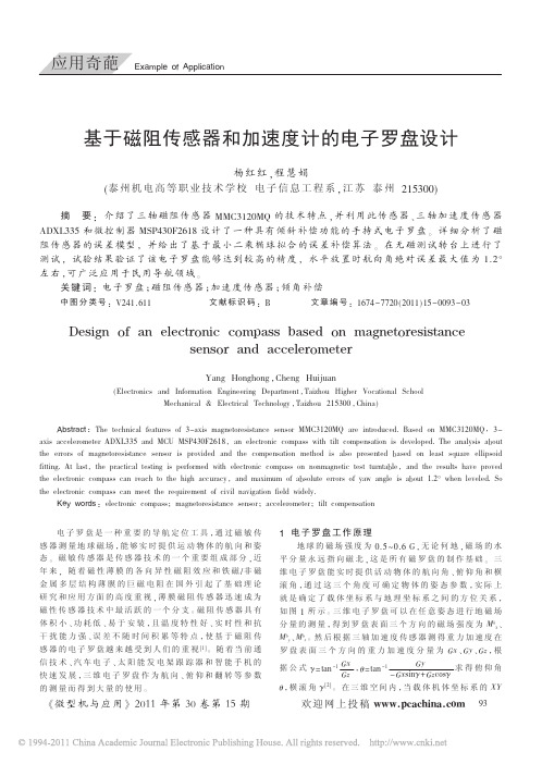
基于磁阻传感器和加速度计的电子罗盘设计
可用图 3(c)表示。
Z
Z
Z
Y
X
Y
X
(b) 存 在 零 位 误 差 及 (a) 无 误 差 情 况
灵敏度误差情况
Y X
(c) 存 在 误 差 及 干 扰 情 况
图 3 磁阻传感器 X、Y、Z 轴数据映射曲面
针对以上误差,本文使用最小二乘椭球拟合磁误差 补偿算法拟合磁阻传感器输出值映射的椭球曲面。 图 3
ADXL335 和 微 控 制 器 MSP430F2618 设 计 了 一 种 具 有 倾 斜 补 偿 功 能 的 手 持 式 电 子 罗 盘 。 详 细 分 析 了 磁
阻传感器的误差模型, 并给出了基于最小二乘椭球拟合的误差补偿算法。 在无磁测试转台上进行了
测试, 试验结果验证了该电子罗盘能够达到较高的精度, 水平放置时航向角绝对误差最大值为 1.2°
《 微 型 机 与 应 用 》 2011 年 第 30 卷 第 15 期
应用奇葩 Example of Application
所示的椭球曲面可用二次多项式方程表示:
!F(x,y,z)=aX2+bY2+cZ2+2fYZ+2gXY+2hYZ+2uX+2vY+2wZ+d (5) a+b+c=1
式(5)描 述 的 最 小 二 乘 问 题 具 有 椭 球 拟 合 唯 一 解 , 且 为全局最小解。 基于最小二乘椭球拟合磁误差补偿算法 的基本设计思路是:使磁阻传感器在环境磁场中均匀地 进行一次三维全方位的旋转,微控制器按一定的采样频 率同步采集原始磁场强度数据,然后进行最小二乘椭球 拟 合 磁 误 差 补 偿 算 法 得 到 式(5)的 系 数 ,根 据 系 数 即 可 求得磁阻传感器三轴输出椭球曲面模型的中心点、灵敏 度和椭球的倾斜度,由此完成磁阻传感器三轴数据的归 一 化过程,最后使用式(4)求得误差修正后的磁航向角值。 4 实验结果分析
电子罗盘基础知识及校准
无人机——磁力计/电子罗盘学习及校准电子罗盘是一种重要的导航工具,能实时提供移动物体的航向和姿态。
随着半导体工艺的进步和手机操作系统的发展,集成了越来越多传感器的智能手机变得功能强大,很多手机上都实现了电子罗盘的功能。
而基于电子罗盘的应用(如Android的Skymap)在各个软件平台上也流行起来。
要实现电子罗盘功能,需要一个检测磁场的三轴磁力传感器和一个三轴加速度传感器。
随着微机械工艺的成熟,意法半导体推出将三轴磁力计和三轴加速计集成在一个封装里的二合一传感器模块LSM303DLH,方便用户在短时间内设计出成本低、性能高的电子罗盘。
本文以LSM303DLH为例讨论该器件的工作原理、技术参数和电子罗盘的实现方法。
1.地磁场和航向角的背景知识如图1所示,地球的磁场象一个条形磁体一样由磁南极指向磁北极。
在磁极点处磁场和当地的水平面垂直,在赤道磁场和当地的水平面平行,所以在北半球磁场方向倾斜指向地面。
用来衡量磁感应强度大小的单位是Tesla或者Gauss(1Tesla=10000Gauss)。
随着地理位置的不同,通常地磁场的强度是0.4-0.6 Gauss。
需要注意的是,磁北极和地理上的北极并不重合,通常他们之间有11度左右的夹角。
图1 地磁场分布图地磁场是一个矢量,对于一个固定的地点来说,这个矢量可以被分解为两个与当地水平面平行的分量和一个与当地水平面垂直的分量。
如果保持电子罗盘和当地的水平面平行,那么罗盘中磁力计的三个轴就和这三个分量对应起来,如图2所示。
图2 地磁场矢量分解示意图实际上对水平方向的两个分量来说,他们的矢量和总是指向磁北的。
罗盘中的航向角(Azimuth)就是当前方向和磁北的夹角。
由于罗盘保持水平,只需要用磁力计水平方向两轴(通常为X轴和Y轴)的检测数据就可以用式1计算出航向角。
当罗盘水平旋转的时候,航向角在0?- 360?之间变化。
2.ST集成磁力计和加速计的传感器模块LSM303DLH2.1 磁力计工作原理在LSM303DLH中磁力计采用各向异性磁致电阻(Anisotropic Magneto-Resistance)材料来检测空间中磁感应强度的大小。
无人机——磁力计电子罗盘学习及校准

无人机——磁力计/电子罗盘学习及校准电子罗盘是一种重要的导航工具,能实时提供移动物体的航向和姿态。随着半导体工艺的进步和手机操作系统的发展,集成了越来越多传感器的智能手机变得功能强大,很多手机上都实现了电子罗盘的功能。而基于电子罗盘的应用(如Android的Skymap)在各个软件平台上也流行起来。要实现电子罗盘功能,需要一个检测磁场的三轴磁力传感器和一个三轴加速度传感器。随着微机械工艺的成熟,意法半导体推出将三轴磁力计和三轴加速计集成在一个封装里的二合一传感器模块LSM303DLH,方便用户在短时间内设计出成本低、性能高的电子罗盘。本文以LSM303DLH为例讨论该器件的工作原理、技术参数和电子罗盘的实现方法。1.地磁场和航向角的背景知识如图1所示,地球的磁场象一个条形磁体一样由磁南极指向磁北极。在磁极点处磁场和当地的水平面垂直,在赤道磁场和当地的水平面平行,所以在北半球磁场方向倾斜指向地面。用来衡量磁感应强度大小的单位是Tesla或者Gauss(1Tesla=10000Gauss)。随着地理位置的不同,通常地磁场的强度是0.4-0.6 Gauss。需要注意的是,磁北极和地理上的北极并不重合,通常他们之间有11度左右的夹角。图1 地磁场分布图地磁场是一个矢量,对于一个固定的地点来说,这个矢量可以被分解为两个与当地水平面平行的分量和一个与当地水平面垂直的分量。如果保持电子罗盘和当地的水平面平行,那么罗盘中磁力计的三个轴就和这三个分量对应起来,如图2所示。图2 地磁场矢量分解示意图实际上对水平方向的两个分量来说,他们的矢量和总是指向磁北的。罗盘中的航向角(Azimuth)就是当前方向和磁北的夹角。由于罗盘保持水平,只需要用磁力计水平方向两轴(通常为X轴和Y轴)的检测数据就可以用式1计算出航向角。当罗盘水平旋转的时候,航向角在0?- 360?之间变化。2.ST集成磁力计和加速计的传感器模块LSM303DLH2.1 磁力计工作原理在LSM303DLH中磁力计采用各向异性磁致电阻(Anisotropic Magneto-Resistance)材料来检测空间中磁感应强度的大小。这种具有晶体结构的合金材料对外界的磁场很敏感,磁场的强弱变化会导致AMR自身电阻值发生变化。在制造过程中,将一个强磁场加在AMR上使其在某一方向上磁化,建立起一个主磁域,与主磁域垂直的轴被称为该AMR的敏感轴,如图3所示。为了使测量结果以线性的方式变化,AMR材料上的金属导线呈45º角倾斜排列,电流从这些导线上流过,如图4所示。由初始的强磁场在AMR材料上建立起来的主磁域和电流的方向有45º的夹角。图3 AMR材料示意图图4 45º角排列的导线当有外界磁场Ha时,AMR上主磁域方向就会发生变化而不再是初始的方向了,那么磁场方向和电流的夹角θ也会发生变化,如图5所示。对于AMR材料来说,θ角的变化会引起AMR自身阻值的变化,并且呈线性关系,如图6所示。图5 磁场方向和电流方向的夹角图6 θ-R特性曲线ST利用惠斯通电桥检测AMR阻值的变化,如图7所示。R1/R2/R3/R4是初始状态相同的AMR电阻,但是R1/R2和R3/R4具有相反的磁化特性。当检测到外界磁场的时候,R1/R2阻值增加∆R而R3/R4减少∆R。这样在没有外界磁场的情况下,电桥的输出为零;而在有外界磁场时电桥的输出为一个微小的电压∆V。图7 惠斯通电桥当R1=R2=R3=R4=R,在外界磁场的作用下电阻变化为∆R时,电桥输出?V正比于?R。这就是磁力计的工作原理。2.2 置位/复位(Set/Reset)电路由于受到外界环境的影响,LSM303DLH中AMR上的主磁域方向不会永久保持不变。LSM303DLH内置有置位/复位电路,通过内部的金属线圈周期性的产生电流脉冲,恢复初始的主磁域,如图8所示。需要注意的是,置位脉冲和复位脉冲产生的效果是一样的,只是方向不同而已。图8 LSM303DLH置位/复位电路置位/复位电路给LSM303DLH带来很多优点:1) 即使遇到外界强磁场的干扰,在干扰消失后LSM303DLH也能恢复正常工作而不需要用户再次进行校正。2) 即使长时间工作也能保持初始磁化方向实现精确测量,不会因为芯片温度变化或内部噪音增大而影响测量精度。3) 消除由于温漂引起的电桥偏差。2.3 LSM303DLH的性能参数LSM303DLH集成三轴磁力计和三轴加速计,采用数字接口。磁力计的测量范围从1.3 Gauss到8.1 Gauss共分7档,用户可以自由选择。并且在20 Gauss以内的磁场环境下都能够保持一致的测量效果和相同的敏感度。它的分辨率可以达到8 mGauss并且内部采用12位ADC,以保证对磁场强度的精确测量。和采用霍尔效应原理的磁力计相比,LSM303DLH的功耗低,精度高,线性度好,并且不需要温度补偿。LSM303DLH具有自动检测功能。当控制寄存器A被置位时,芯片内部的自测电路会产生一个约为地磁场大小的激励信号并输出。用户可以通过输出数据来判断芯片是否正常工作。作为高集成度的传感器模组,除了磁力计以外LSM303DLH还集成一颗高性能的加速计。加速计同样采用12位ADC,可以达到1mg的测量精度。加速计可运行于低功耗模式,并有睡眠/唤醒功能,可大大降低功耗。同时,加速计还集成了6轴方向检测,两路可编程中断接口。3. ST电子罗盘方案介绍一个传统的电子罗盘系统至少需要一个三轴的磁力计以测量磁场数据,一个三轴加速计以测量罗盘倾角,通过信号条理和数据采集部分将三维空间中的重力分布和磁场数据传送给处理器。处理器通过磁场数据计算出方位角,通过重力数据进行倾斜补偿。这样处理后输出的方位角不受电子罗盘空间姿态的影响,如图9所示。图9 电子罗盘结构示意图LSM303DLH将上述的加速计、磁力计、A/D转化器及信号条理电路集成在一起,仍然通过I2C总线和处理器通信。这样只用一颗芯片就实现了6轴的数据检测和输出,降低了客户的设计难度,减小了PCB板的占用面积,降低了器件成本。LSM303DLH的典型应用如图10所示。它需要的周边器件很少,连接也很简单,磁力计和加速计各自有一条I2C总线和处理器通信。如果客户的I/O接口电平为1.8V,Vdd_dig_M、Vdd_IO_A和Vdd_I2C_Bus 均可接1.8V供电,Vdd使用2.5V以上供电即可;如果客户接口电平为2.6V,除了Vdd_dig_M要求1.8V以外,其他皆可以用2.6V。在上文中提到,LSM303DLH需要置位/复位电路以维持AMR的主磁域。C1和C2为置位/复位电路的外部匹配电容,由于对置位脉冲和复位脉冲有一定的要求,建议用户不要随意修改C1和C2的大小。图10 LSM303DLH典型应用电路图对于便携式设备而言,器件的功耗非常重要,直接影响其待机的时间。LSM303DLH可以分别对磁力计和加速计的供电模式进行控制,使其进入睡眠或低功耗模式。并且用户可自行调整磁力计和加速计的数据更新频率,以调整功耗水平。在磁力计数据更新频率为7.5Hz、加速计数据更新频率为50Hz时,消耗电流典型值为0.83mA。在待机模式时,消耗电流小于3uA。4. 铁磁场干扰及校准电子指南针主要是通过感知地球磁场的存在来计算磁北极的方向。然而由于地球磁场在一般情况下只有微弱的0.5高斯,而一个普通的手机喇叭当相距2厘米时仍会有大约4高斯的磁场,一个手机马达在相距2厘米时会有大约6高斯的磁场,这一特点使得针对电子设备表面地球磁场的测量很容易受到电子设备本身的干扰。磁场干扰是指由于具有磁性物质或者可以影响局部磁场强度的物质存在,使得磁传感器所放置位置上的地球磁场发生了偏差。如图11所示,在磁传感器的XYZ 坐标系中,绿色的圆表示地球磁场矢量绕z 轴圆周转动过程中在XY平面内的投影轨迹,再没有外界任何磁场干扰的情况下,此轨迹将会是一个标准的以O(0,0)为中心的圆。当存在外界磁场干扰的情况时,测量得到的磁场强度矢量α将为该点地球磁场β与干扰磁场γ的矢量和。记作:图11 磁传感器XY坐标以及磁力线投影轨迹一般可以认为,干扰磁场γ在该点可以视为一个恒定的矢量。有很多因素可以造成磁场的干扰,如摆放在电路板上的马达和喇叭,还有含有铁镍钴等金属的材料如屏蔽罩,螺丝,电阻, LCD背板以及外壳等等。同样根据安培定律有电流通过的导线也会产生磁场,如图12。图12 电流对磁场产生的影响为了校准这些来自电路板的磁场干扰,主要的工作就是通过计算将γ求出。4.1 平面校准方法针对XY轴的校准,将配备有磁传感器的设备在XY平面内自转,如图11,等价于将地球磁场矢量绕着过点O(γx,γy)垂直于XY平面的法线旋转, 而红色的圆为磁场矢量在旋转过程中在XY平面内投影的轨迹。这可以找到圆心的位置为((Xmax + Xmin)/2, (Ymax + Ymin)/2). 同样将设备在XZ平面内旋转可以得到地球磁场在XZ平面上的轨迹圆,这可以求出三维空间中的磁场干扰矢量γ(γx, γy, γz).4.2 立体8字校准方法一般情况下,当带有传感器的设备在空中各个方向旋转时,测量值组成的空间几何结构实际上是一个圆球,所有的采样点都落在这个球的表面上,如图13所示,这一点同两维平面内投影得到的圆类似。图13 地球磁场空间旋转后在传感器空间坐标内得到球体这种情况下,可以通过足够的样本点求出圆心O(γx, γy, γz), 即固定磁场干扰矢量的大小及方向。公式如下:8字校准法要求用户使用需要校准的设备在空中做8字晃动,原则上尽量多的让设备法线方向指向空间的所有8个象限,如图14所示。图14 设备的空中8字校准示意图4.2 十面校准方法同样,通过以下10面校准方法,也可以达到校准的目的。图15 10面交准法步骤如图16所示,经过10面校准方法之后,同样可以采样到以上所述球体表面的部分轨迹,从而推导出球心的位置,即固定磁场干扰矢量的大小及方向。图16 10面校准后的空间轨迹5.倾斜补偿及航偏角计算经过校准后电子指南针在水平面上已经可以正常使用了。但是更多的时候手机并不是保持水平的,通常它和水平面都有一个夹角。这个夹角会影响航向角的精度,需要通过加速度传感器进行倾斜补偿。对于一个物体在空中的姿态,导航系统里早已有定义,如图17所示,Android中也采用了这个定义。Pitch(Φ)定义为x轴和水平面的夹角,图示方向为正方向;Roll(θ)定义为y轴和水平面的夹角,图示方向为正方向。由Pitch角引起的航向角的误差如图18所示。可以看出,在x轴方向10度的倾斜角就可以引起航向角最大7-8度的误差。图17 Pitch角和Roll角定义图18 Pitch角引起的航向角误差手机在空中的倾斜姿态如图19所示,通过3轴加速度传感器检测出三个轴上重力加速度的分量,再通过式2可以计算出Pitch和Roll。图19 手机在空中的倾斜姿态式3可以将磁力计测得的三轴数据(XM,YM ,ZM)通过Pitch和Roll 转化为式1中计算航向角需要的Hy和Hx。之后再利用式1计算出航向角。6.Android平台指南针的实现在当前流行的android 手机中,很多都配备有指南针的功能。为了实现这一功能,只需要配备有ST提供的二合一传感模块LSM303DLH,ST 提供整套解决方案。Android中的软件实现可以由以下框图表示:其中包括:BSP ReferenceLinux Kernel Driver (LSM303DLH_ACC + LSM303DLH_MAG)HAL Library(Sensors_lsm303dlh + Liblsm303DLH) for sensors.default.so经过library 的计算,上层的应用可以很轻松的运用由Android定义由Library提供的航偏角信息进行应用程序的编写。。
AN3192Using LSM303DLH for a tilt compensated electronic compass
AN3192Application note Using LSM303DLH for a tilt compensated electronic compassIntroductionThis application note describes the method for building a tilt compensated electroniccompass using an LSM303DLH sensor module.The LSM303DLH is a 5 x 5 x 1 mm with LGA-28L package IC chip that includes a 3D digitallinear acceleration and a 3D digital magnetic sensor. It has a selectable linear accelerationfull scale range of ±2g / ±4g / ±8g and a selectable magnetic field full scale range of ±1.3 /±1.9 / ±2.5 / ±4.0 / ±4.7 / ±5.6 / ±8.1 gauss. Both the magnetic sensor and theaccelerometer parts can be powered down separately to reduce power consumption.Sensor measurements can be acquired by a microcontroller through an I2C serial businterface.The key features of the system are:■One single chip solution■I2C communication interface■Tilt compensationSection1 describes the basics of the electronic compass. Section2 presents a typicalhardware connection between the LSM303DLH and a microcontroller and sample code forsensor data acquisition. Section3 focuses on the methods of the determination of sensorcalibration parameters. Section4 shows the methods of lab testing and field testing forchecking the electronic compass performance. Section5 gives recommendations formicrocontroller firmware implementation when designing a standalone tilt compensatedelectronic compass.August 2010Doc ID 17353 Rev 11/34Contents AN3192Contents1Electronic compass basics . . . . . . . . . . . . . . . . . . . . . . . . . . . . . . . . . . . 51.1Definitions . . . . . . . . . . . . . . . . . . . . . . . . . . . . . . . . . . . . . . . . . . . . . . . . . . 51.2Heading calculation . . . . . . . . . . . . . . . . . . . . . . . . . . . . . . . . . . . . . . . . . . 61.3Tilt compensation . . . . . . . . . . . . . . . . . . . . . . . . . . . . . . . . . . . . . . . . . . . . 61.4Electronic compass system . . . . . . . . . . . . . . . . . . . . . . . . . . . . . . . . . . . . 71.5Getting started with LSM303DLH . . . . . . . . . . . . . . . . . . . . . . . . . . . . . . . . 82LSM303DLH configuration . . . . . . . . . . . . . . . . . . . . . . . . . . . . . . . . . . . . 92.1Typical hardware connection . . . . . . . . . . . . . . . . . . . . . . . . . . . . . . . . . . . 92.2LSM303DLH accelerometer data acquisition . . . . . . . . . . . . . . . . . . . . . . . 92.3LSM303DLH magnetic sensor data acquisition . . . . . . . . . . . . . . . . . . . . 103Calibrating the LSM303DLH . . . . . . . . . . . . . . . . . . . . . . . . . . . . . . . . . . 123.1LSM303DLH accelerometer calibration . . . . . . . . . . . . . . . . . . . . . . . . . . 123.2LSM303DLH magnetic sensor calibration . . . . . . . . . . . . . . . . . . . . . . . . 123.2.1Terminology . . . . . . . . . . . . . . . . . . . . . . . . . . . . . . . . . . . . . . . . . . . . . . 134Testing the electronic compass . . . . . . . . . . . . . . . . . . . . . . . . . . . . . . . 154.1Lab testing . . . . . . . . . . . . . . . . . . . . . . . . . . . . . . . . . . . . . . . . . . . . . . . . 154.1.1Absolute heading testing . . . . . . . . . . . . . . . . . . . . . . . . . . . . . . . . . . . . 154.1.2Tilt compensation testing . . . . . . . . . . . . . . . . . . . . . . . . . . . . . . . . . . . . 164.2Field testing . . . . . . . . . . . . . . . . . . . . . . . . . . . . . . . . . . . . . . . . . . . . . . . 164.2.1Relative heading testing . . . . . . . . . . . . . . . . . . . . . . . . . . . . . . . . . . . . . 174.2.2Tilt compensation testing . . . . . . . . . . . . . . . . . . . . . . . . . . . . . . . . . . . . 17 5Firmware implementation . . . . . . . . . . . . . . . . . . . . . . . . . . . . . . . . . . . . 18Appendix A LSM303DLH pitch/roll/heading calculation. . . . . . . . . . . . . . . . . . . 19A.1Pitch/roll calculation. . . . . . . . . . . . . . . . . . . . . . . . . . . . . . . . . . . . . . . . . . 20A.2Heading calculation. . . . . . . . . . . . . . . . . . . . . . . . . . . . . . . . . . . . . . . . . . 22 Appendix B Accelerometer calibration method. . . . . . . . . . . . . . . . . . . . . . . . . . 242/34 Doc ID 17353 Rev 1AN3192ContentsAppendix C Magnetic sensor calibration method. . . . . . . . . . . . . . . . . . . . . . . . 27C.1Step 1: Soft-iron effect verification . . . . . . . . . . . . . . . . . . . . . . . . . . . . . . 27C.2Step 2: Hard-iron, soft-iron and scale factor compensation . . . . . . . . . . . 27C.3Step 3: Misalignment error compensation. . . . . . . . . . . . . . . . . . . . . . . . . 30 6References . . . . . . . . . . . . . . . . . . . . . . . . . . . . . . . . . . . . . . . . . . . . . . . . 32 7Revision history . . . . . . . . . . . . . . . . . . . . . . . . . . . . . . . . . . . . . . . . . . . 33Doc ID 17353 Rev 13/34List of figures AN3192 List of figuresFigure 1.Body coordinates and attitude angles. . . . . . . . . . . . . . . . . . . . . . . . . . . . . . . . . . . . . . . . . . 5 Figure 2.Heading calculation . . . . . . . . . . . . . . . . . . . . . . . . . . . . . . . . . . . . . . . . . . . . . . . . . . . . . . . 6 Figure 3.Handheld device at tilted position. . . . . . . . . . . . . . . . . . . . . . . . . . . . . . . . . . . . . . . . . . . . . 7 Figure 4.Block diagram of electronic compass system. . . . . . . . . . . . . . . . . . . . . . . . . . . . . . . . . . . . 7 Figure 5.Typical hardware connection . . . . . . . . . . . . . . . . . . . . . . . . . . . . . . . . . . . . . . . . . . . . . . . . 9 Figure b testing setup . . . . . . . . . . . . . . . . . . . . . . . . . . . . . . . . . . . . . . . . . . . . . . . . . . . . . . . . 15 Figure 7.Field testing setup. . . . . . . . . . . . . . . . . . . . . . . . . . . . . . . . . . . . . . . . . . . . . . . . . . . . . . . . 16 Figure 8.Electronic compass coordinate system . . . . . . . . . . . . . . . . . . . . . . . . . . . . . . . . . . . . . . . 19 Figure 9.Rotation procedures. . . . . . . . . . . . . . . . . . . . . . . . . . . . . . . . . . . . . . . . . . . . . . . . . . . . . . 20 Figure 10.Heading calculation . . . . . . . . . . . . . . . . . . . . . . . . . . . . . . . . . . . . . . . . . . . . . . . . . . . . . . 22 Figure 11.3D rotations plus three 2D full round rotations. . . . . . . . . . . . . . . . . . . . . . . . . . . . . . . . . . 27 Figure 12.After hard-iron, soft-iron, and scale factor compensation. . . . . . . . . . . . . . . . . . . . . . . . . . 28 Figure 13.After misalignment compensation. . . . . . . . . . . . . . . . . . . . . . . . . . . . . . . . . . . . . . . . . . . . 31 4/34 Doc ID 17353 Rev 11 Electronic compass basicsThe strength of the earth's magnetic field is about 0.5 to 0.6 gauss and has a componentparallel to the earth's surface that always points toward the magnetic north pole. In thenorthern hemisphere, this field points down. At the equator, it points horizontally and in thesouthern hemisphere, it points up. This angle between the earth’s magnetic field and thehorizontal plane is defined as an inclination angle. Another angle between the earth'smagnetic north and geographic north is defined as a declination angle in the range of ± 20ºdepending on the geographic location.A tilt compensated electronic compass system requires a 3-axis magnetic sensor and a 3-axis accelerometer sensor. The accelerometer is used to measure the tilt angles of pitchand roll for tilt compensation. And the magnetic sensor is used to measure the earth’smagnetic field and then to determine the heading angle with respect to the magnetic north.If the heading with respect to the geographic north is required, the declination angle at thecurrent geographic location should be compensated to the magnetic heading.1.1 DefinitionsFor compass applications in a handheld device such as a cell phone or a PDA, the aircraftconvention is widely used to define the device body coordinates and three attitude anglespitch, roll and heading as shown in Figure1.Figure 1.Body coordinates and attitude anglesFrom Figure1, the device (or aircraft) body coordinates X b/Y b/Z b are defined asforward/right/down based on the right-hand rule.Three attitude angles are referenced to the local horizontal plane which is perpendicular toearth’s gravity.Heading is defined as the angle between the X b axis and the magnetic north on thehorizontal plane measured in a clockwise direction when viewing from the top of the device(or aircraft).Pitch is defined as the angle between the X b axis and the horizontal plane. When rotatingthe device around the Y b axis with the X b axis moving upwards, pitch is positive andincreasing.Roll is defined as the angle between the Yb axis and the horizontal plane. When rotating thedevice around the X b axis with the Y b axis moving downwards, roll is positive andincreasing.Doc ID 17353 Rev 15/346/34 Doc ID 17353 Rev 11.2 Heading calculationWhen the device is at a leveled position, pitch and roll angles are 0°. Then the headingangle can be determined as shown in Figure 2.Local earth magnetic field H has a fixed component H h on the horizontal plane pointing tothe earth’s magnetic north. This component can be measured by the magnetic sensorsensing axes X M and Y M that are named as X h and Y h . Then the heading angle is calculatedas:Equation 1In Figure 2, when the device body X b axis is parallel to H h which is pointing to the magneticnorth, then X h = max and Y h = 0 so that heading = 0°. Rotating the device clockwise on thehorizontal plane, the heading increases. When X h = 0 and Y h = min, then heading = 90°.Keep rotating until X h = min and Y h = 0, then heading = 180°. And so on. After a full round360° rotation, the user sees a centered circle if plotting X h and Y h values coming from themagnetic sensor measurements.1.3 Tilt compensationIf the handheld device is tilted, then the pitch and roll angles are not equal to 0° as shown inFigure 3, where the pitch and roll can be measured by a 3-axis accelerometer. Therefore,the magnetic sensor measurements X M , Y M , and Z M need to be compensated to obtain X hand Y h as shown in Equation 2. And then apply Equation 1 for the heading calculation.)X /Y arctan(Heading h h =Doc ID 17353 Rev 17/34Equation 2Where, X M , Y M , and Z M are magnetic sensor measurements.1.4 Electronic compass systemFigure 4 below shows the block diagram of an electronic compass system. A microcontroller(MCU) is used to collect the 3-axis accelerometer raw data for the pitch and roll calculationand collect the 3-axis magnetic sensor raw data for the heading calculation. The following isthe procedure for building a working electronic compass system.●Hardware design to make sure the MCU can get clean raw data from the accelerometer and the magnetic sensor ●Accelerometer calibration to obtain parameters to convert accelerometer raw data to normalized values for pitch and roll calculation ●Magnetic sensor calibration to obtain parameters to convert magnetic sensor raw data to normalized values for the heading calculation ●Test the performance of the electronic compass system.Pitchcos Roll sin Z Roll cos Y Pitch sin Roll sin X Y Pitchsin Z Pitch cos X X M M M h M M h −+=+=1.5 Getting started with LSM303DLHThe LSM303DLH from STMicroelectronics is a 6D sensor module that contains a 3Daccelerometer and a 3D magnetic sensor. It has an I2C digital interface so that the analog todigital converter is avoided. The MCU can collect 6D sensor data directly through the I2Cinterface.After understanding the electronic compass basics, it is time to get started on building aworking electronic compass system based on the LSM303DLH 6D sensor module. Thedetailed definition and pitch/roll/heading calculation are described in Appendix A.8/34 Doc ID 17353 Rev 1AN3192LSM303DLH configuration Doc ID 17353 Rev 19/342 L SM303D L H configuration2.1 Typical hardware connectionFigure 5 shows a typical hardware connection between the LSM303DLH and amicrocontroller. The +3 V power supply is used to power the LSM303DLH and the +1.8 Vpower supply is used for digital IO lines.The LSM303DLH is an I 2C slave and the microcontroller is an I 2C master. When designingthe hardware, the user should pay attention to the following:●Some reserved pins not shown in Figure 5 should be connected to their corresponding pins according to the LSM303DLH datasheet ●Power supply decoupling ceramic capacitors C3 (10 µF) and C4 (0.1 µF) should be placed as near as possible to the Vdd pin 6●Choose a microcontroller that has a built-in I 2C controller. If a bit-banging schemeimplemented in the microcontroller's firmware is used, pay attention to the I 2Ccommunication timing specifications●The +3 V and +1.8 V power supply should be regulated and clean to reduce the noise In addition, the handheld device may have high current active components, for example, anRF amplifier circuit. It may also have ferromagnetic metal materials that a magnet wouldstick to. These generate magnetic field distortion to the earth’s magnetic field. Even thoughthe magnetic sensor calibration can compensate these hard-iron and soft-iron distortions, itis recommended to place the LSM303DLH onto the device PCB as far away as possiblefrom the above distortions.2.2 LSM303DLH accelerometer data acquisitionSA0_A pin 4 in Figure 5 is tied to ground. So the 7-bit I 2C slave address for theaccelerometer, accordingly, is 0011000b or 0x18. For electronic compass applications, a fullscale range of ±2 gauss and bandwidth of 10 Hz should be sufficient.LSM303DLH configuration AN3192 After power-on of the LSM303DLH, two registers, CTRL_REG1_A (20h) andCTRL_REG4_A (23h) need to be configured. Write 0x27 to the CTRL_REG1_A register tobring the accelerometer into normal operation mode with ODR 50Hz. Write 0x40 to theCTRL_REG4_A register to keep a full scale range ±2 gauss in continuous data updatemode and change the little-endian to a big-endian structure.The following sample C code shows how to acquire accelerometer data:unsigned char ACC_Data[6];int Ax, Ay, Az;void main(void){Write(0x18, 0x20, 0x27);//set CTRL_REG1_A registerWrite(0x18, 0x23, 0x40);//set CTRL_REG4_A registerWhile (1){ACC_Data[0] = Read(0x18, 0x28);//read OUT_X_L_A (MSB)ACC_Data[1] = Read(0x18, 0x29);//read OUT_X_H_A (LSB)ACC_Data[2] = Read(0x18, 0x2A);//read OUT_Y_L_A (MSB)ACC_Data[3] = Read(0x18, 0x2B);//read OUT_Y_H_A (LSB)ACC_Data[4] = Read(0x18, 0x2C);//read OUT_Z_L_A (MSB)ACC_Data[5] = Read(0x18, 0x2D);//read OUT_Z_H_A (LSB)Ax = (int) (ACC_Data[0] << 8) + ACC_Data[1];Ay = (int) (ACC_Data[2] << 8) + ACC_Data[3];Az = (int) (ACC_Data[4] << 8) + ACC_Data[5];}}2.3 LSM303DLH magnetic sensor data acquisitionThe 7-bit I2C slave address for the magnetic sensor is 0011110b or 0x1E. For electroniccompass applications, a full scale range of ±1.3 gauss and ODR at 30Hz should besufficient.After power-on of the LSM303DLH, two registers CRA_REG_M (00h) and MR_REG_M(02h), need to be configured. Write 0x14 to the CRA_REG_M register to change the ODRfrom 15 Hz to 30 Hz. Write 0x00 to the MR_REG_M register to put the magnetic sensor intocontinuous mode from sleep mode.The following sample C code shows how to acquire magnetic sensor data:unsigned char temp, MR_Data[6];int Mx, My, Mz;void main(void)10/34 Doc ID 17353 Rev 1AN3192LSM303DLH configuration{Write(0x1E, 0x00, 0x14);//set CRA_REG_M registerWrite(0x1E, 0x02, 0x00);//set MR_REG_M registerWhile (1){Temp = Read(0x1E, 0x02); //read MR_REG_MMR_Data[0] = ReadCurrentAddress(); //read OUT_X_H_M (MSB)MR_Data[1] = ReadCurrentAddress(); //read OUT_X_L_M (LSB)MR_Data[2] = ReadCurrentAddress(); //read OUT_Y_H_M (MSB)MR_Data[3] = ReadCurrentAddress(); //read OUT_Y_L_M (LSB)MR_Data[4] = ReadCurrentAddress();//read OUT_Z_H_M (MSB)MR_Data[5] = ReadCurrentAddress(); //read OUT_Z_L_M (LSB)Mx = (int) (MR_Data[0] << 8) + MR_Data[1];My = (int) (MR_Data[2] << 8) + MR_Data[3];Mz = (int) (MR_Data[4] << 8) + MR_Data[5];}}The pointer address of the magnetic sensor of the LSM303DLH has an automatic updatefeature. After a read of the MR_REG_M (02h) register, the address pointer automaticallyincreases 1 to 03h which is the OUT_X_H_M register. After a read of the OUT_X_H_Mregister, the address pointer increases 1 to the OUT_X_L_M register. So one functionReadCurrentAddress() can be used to read 6 bytes of magnetic sensor X-Y-Z datacontinuously. Please refer to the LSM303DLH datasheet; Sensor module: 3-axisaccelerometer and 3-axis magnetometer, for more details.Doc ID 17353 Rev 111/3412/34 Doc ID 17353 Rev 13Calibrating the LSM303DLH 3.1 LSM303DLH accelerometer calibrationAll ST MEMS accelerometers are factory calibrated, allowing the user to avoid any furthercalibration for most of the applications now present in the market. However, to reach aheading accuracy of below 2°, an easy calibration procedure is hereafter described. Afterthe LSM303DLH is installed in the handheld device, it is necessary to calibrate theaccelerometer part again at the handheld device's manufacturers in order to determine theoffset, the scale factor, and the misalignment matrix with respect to the device body axesX b /Y b /Z b . After the device is released to the market, end users don't need to perform furtheraccelerometer calibration in field.The relationship between the normalized A x1, A y1, and A z1 and the accelerometer rawmeasurements Ax, Ay, and Az can be expressed as,Equation 3where [A_m] is a 3x3 misalignment matrix between the accelerometer sensing axes and thedevice body axes; A_SCi (i = x, y, z) is the scale factor and A_OSi is the offset.The goal of the accelerometer calibration is to determine 12 parameters from ACC10 toACC33 so that with any given raw measurements at arbitrary positions, the normalizedvalues can be obtained. Therefore, pitch and roll can be calculated by Equation 10 inAppendix A .The calibration can be performed at 6 stationary positions as shown in Table 2 in AppendixA. Collect 5 to 10 second accelerometer raw data at each position with known A x1, A y1, andA z1. Then apply the least square method to obtain the optimal 12 accelerometer calibrationparameters. Please refer to Appendix B for the accelerometer calibration.In order to get better pitch/roll accuracy, the user can add 4 more stationary positions foraccelerometer calibration. They are: 2 positions with A x = 0, A y = ±0.707g, A z = -0.707g, and2 positions with A x = ±0.707g, A y = 0, A z = -0.707g.3.2 LSM303DLH magnetic sensor calibrationLSM303DLH has a magnetic field resolution of 8 mGauss at Vdd = +3 V . And the averagemagnitude of the horizontal magnetic field component is in about the 200 mGauss range(more at the equator, less near the magnetic poles). Therefore, the expected headingaccuracy is about 2.3° [=arctan (8/200)].At a full scale range of ±1.3 gauss, the sensitivity of the LSM303DLH's magnetic sensor is1055 LSB/gauss for the X/Y axis and 950 LSB/gauss for the Z axis. For example in SanFrancisco, California, the earth’s magnetic field strength is 0.49932 gauss with a declination[]⎥⎥⎥⎦⎤⎢⎢⎢⎣⎡+⎥⎥⎥⎦⎤⎢⎢⎢⎣⎡⋅⎥⎥⎥⎦⎤⎢⎢⎢⎣⎡=⎥⎥⎥⎦⎤⎢⎢⎢⎣⎡−−−⋅⎥⎥⎥⎦⎤⎢⎢⎢⎣⎡=⎥⎥⎥⎦⎤⎢⎢⎢⎣⎡302010z y x 333231232221131211z z y y x x z y x 3x 31z 1y 1x ACC ACC ACC A A A ACC ACC ACC ACC ACC ACC ACC ACC ACC OS _A A OS _A A OS _A A SC _A /1000SC _A /1000SC _A /1m _A A A ADoc ID 17353 Rev 113/34angle of 15.5 º and an inclination angle of 61.4º. Then the Z b component, in Figure 1, is0.438 gauss. So the Mz raw measurement should be around 950 x 0.438 = +416 LSBs.The relationship between the normalized M x1, M y1, and M z1 and the magnetic sensor rawmeasurements M x , M y , and M z can be expressed as,Equation 4where [M_m] is a 3x3 misalignment matrix between the magnetic sensor sensing axes andthe device body axes; M_SCi (i = x, y, z) is the scale factor and M_OSi is the offset causedby hard-iron distortion; [M_si] is a 3x3 matrix caused by soft-iron distortion.The goal of the magnetic sensor calibration is to determine the parameters from MR10 toMR33 so that with any given raw measurements at arbitrary positions, the normalizedvalues can be obtained. Therefore, the heading can be calculated by Equation 12 and 13 inAppendix A for tilt compensation.3.2.1 TerminologyHard-iron interference magnetic field is normally generated by ferromagnetic materials withpermanent magnetic fields that are part of the handheld device structure. These materialscould be permanent magnets or magnetized iron or steel. They are time invariant. Theseunwanted magnetic fields are superimposed on the output of the magnetic sensormeasurements of the earth's magnetic field. The effect of this superposition is to bias themagnetic sensor outputs. It is described as M_OSi (i = x, y, z) or MR 10, MR 20 and MR 30 inEquation 4.A soft-iron interference magnetic field is generated by the items inside the handheld device.They could be current carrying traces on the PCB or magnetically soft materials. Theygenerate a time varying magnetic field that is superimposed on the magnetic sensor outputin response to the earth's magnetic field. The effect of the soft-iron distortion is to make afull round rotation circle become a tilted ellipse. It is described as the [M_si] 3x3 matrix inEquation 4.Scale factor error is defined as the mismatch of the sensitivity of the magnetic sensorsensing axes. Ideally, the 3-axis magnetic sensors that make up the triad are identical. Inreality, however, this may not be the case. Each magnetic sensor channel may have differentsensitivities. The effect of the scale factor error causes the full round rotation circle tobecome an ellipse. It is described as M_SCi (i = x, y, z) in Equation 4.Misalignment error is defined as the angles between the magnetic sensor sensing axes andthe device body axes. When assembling the LSM303DLH in the handheld device, thesesmall angles always exist and need to be compensated. It is described as [M_m] 3x3 matrixin Equation 4.Magnetic sensor calibration can be performed by 3 full round rotations along with devicebody axis Z b down, Y b down, and X b down respectively, at a leveled smooth surface withouta nearby interference magnetic field. They are 2D rotations. The rotation speed should be[][]⎥⎥⎥⎦⎤⎢⎢⎢⎣⎡−−−⋅⎥⎥⎥⎦⎤⎢⎢⎢⎣⎡=⎥⎥⎥⎦⎤⎢⎢⎢⎣⎡−−−⋅⎥⎥⎥⎦⎤⎢⎢⎢⎣⎡=⎥⎥⎥⎦⎤⎢⎢⎢⎣⎡30z 20y 10x 333231232221131211z zy y x x 3x 3z y x 3x 31z 1y 1x MR M MR M MR M MR MR MR MR MR MR MR MR MR OS _M M OS _M M OS _M M si _M SC _M /1000SC _M /1000SC _M /1m _M M M Mslow in order to collect as many data points as possible. But it does not require constantrotation speed and an accurate sampling time interval. The full round rotation can beclockwise or counterclockwise. Collected magnetic sensor raw data of 3 full round rotationsis used to accurately determine the 12 magnetic sensor calibration parameters.3D random rotations are performed by rotating the handheld device in random directions. Ifthe handheld device doesn't have hard-iron and soft-iron interference magnetic fields, andthe scale factor of each axis is identical, and the LSM303DLH magnetic sensor's sensingaxes are aligned to the device body axes, then each full round rotation forms a centeredcircle with the same radius and the 3D rotations form a centered sphere. However, due tothe hard-iron and soft-iron magnetic field distortions, and the errors of the scale factor andthe misalignment, the centered sphere becomes a shifted, tilted ellipsoid when plotting thecollected magnetic sensor raw data.The 3 steps for magnetic sensor calibration are presented in Appendix C.Please note that the magnetic sensor calibration can only compensate the hard-iron andsoft-iron interference magnetic field generated by the handheld device itself. This meansthat during full round rotations of the calibration, the hard-iron and soft-iron fields also rotatewith the device.The electronic compass is sensitive to environmental magnetic interference fields outside ofthe handheld device. A single Z-axis gyro chip can be used to aid the compass whenenvironmental magnetic interference is detected.14/34 Doc ID 17353 Rev 1Doc ID 17353 Rev 115/344 Testing the electronic compassAfter the calibration parameters for the accelerometer and the magnetic sensor of theLSM303DLH have been determined, it is necessary to check the performance of theelectronic compass. This could be carried out with accurate lab testing and rough fieldtesting. The expected pitch/roll/heading accuracy is shown in Table 1.4.1 L ab testingA convenient setup for accurate lab testing is a wooden platform with 3 degrees of rotationfreedom, as shown in Figure 6.There should be no strong external interference magnetic field close to the woodenplatform. CRT monitors, power cords, electrical equipment, and metallic frames, sometimeshidden in the structure below the wooden platform, have to be removed during testing. If thelocal magnetic north direction is known by means of a reference magnetometer, a sign canbe placed on a side panel and the handheld device fixed to the top of the platform. Anoptical head may be used to align X b to the mark.4.1.1 Absolute heading testing●Level the wooden platform ●Align the handheld device X b axis to the local magnetic north direction mark on the wall ●Check the heading output of the electronic compass. It should be 0º ± 2º. This is the absolute heading accuracy at 0º●Rotate the wooden platform horizontally clockwise or counterclockwise at a random angle which can be read from the marks on the platform. Then compare the compass Table 1.Expected pitch/roll/heading accuracyParameterValue Heading accuracy< 2° RMS (tilt within ±50°), range: 0° ~ 359.9°Pitch and roll accuracy< 1° RMS (tilt within ±50°), range: -90° ~ +90°Resolution 0.1° for heading, pitch, and rollheading output with the known heading angle. The difference should be within ± 2º.This is the absolute heading accuracy at random position.●Fix a certain position. Rotate the platform back and forth and then stop at the sameposition. The repeatability error also should be within ± 2º.compensationtesting4.1.2 Tilt●Level the wooden platform●Align the handheld device X b axis to any direction. Record the compass heading outputvalue●Rotate the platform around the Y b axis to generate a plus or minus pitch angle whichcan be read from the marks on the wooden platform. Compare the compass pitchoutput with the known pitch angle. The difference should be within ± 1º (see Table1).At the same time the change of the compass heading output should be within ± 2ºwhich means the compass is tilt compensated●Level the wooden platform●Align the handheld device X b axis to any direction. Record the compass heading outputvalue●Rotate the platform around the X b axis to generate a plus or minus roll angle which canbe read from the marks on the platform. Compare the compass roll output with theknown roll angle. The difference should be within ± 1º (see Table1). At the same timethe change of the compass heading output should be within ± 2º which means thecompass is tilt compensated.4.2 FieldtestingIn any physical situations outside the lab, rough field testing can be performed. A woodentable with a smooth surface is required. The surface does not have to be leveled. Drawsome lines, for example, 20º apart on a white sheet of paper as shown in Figure7.16/34 Doc ID 17353 Rev 1。
基于MEMS传感器的微小型三维电子罗盘设计
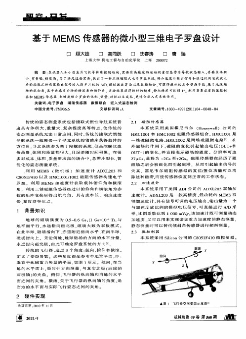
小、 重量 轻 、 度 高 。 了 满足 这 些 需 要 , 出 了一 种 三 维磁 阻 式 电子 罗盘 系统 , 加 速度 计输 出信 号 和 经 过 仪 用 运放 放 大 精 为 提 将
后 的磁 阻 式传 感 器输 出信 号 输 入 到 单 片机 的 D. 过 滤 波算 法 以及 数 据 融合 . 获得 载 体 的 三 个 姿 态参 数 : 于地 球 磁 通 可 基
基 于 ME 感器 的微 小 型 三维 电子 罗盘设 计 ቤተ መጻሕፍቲ ባይዱ MS传
口 顾 大雄 口 高 同跃 口 沈春 涛
上海
口
唐
瑞
上 海 大 学 机 电工 程 与 自动 化 学 院
207 002
摘
要 : 机 器人 和 小型 直 升 飞 机 等 特 殊 控 制领 域 , 在 需要 有 高精 度 的 运 动 测 量 信 息 作 为 导航 状 态输 入 , 要 求 体 积 并
场 的航 向 角 . 于 地球 重 力场 的 横 滚 角和 俯仰 角 实验 结 果 获 得 较 好 的精 度 . 态精 度 可达 到 1 。 用 高集 成 度 的微 控 制 基 静 。 利
器 和 MEMS传 感 器 , 幅 度 缩 小 罗 盘 的 体 积 、 量 、 耗 以 及 成 本 , 适 合 嵌 入 式 系 统 使 用 。 大 重 功 更
利 用 MEMS 微 机 械 ) 加 速 度 计 ADXL 0 和 f 23 C8 5 F 1 以 及 HMC1 0 / 0 2磁 阻 传 感 器 构 建 电 子 0 140 0 11 0
OU 一) 变 化 . 直 接 表 示 磁 场 的 强 度 。 分 辨 率 可 达 T 的 并 2 1 . 程 为 一 Gs至 + Gs 磁 阻 传 感 器 在 经 历 了 强 7. z Gs 量 2 2 。 磁 场 之 后 会 被 磁 化 而 引 起 磁 滞 . 从 而 引 起 输 出 信 号 的
毕业设计 基于磁阻式传感器的电子罗盘的设计
本科毕业论文便携式电子罗盘软件设计与校准学生姓名:沈彤学号:20120214241学院:机电工程学院专业:机械设计制造及其自动化(机电一体化)指导教师:葛海浪 (助教)2016年 5 月 9 日目录引言 (4)第一章.电子罗盘的测量与倾角补偿原理 (5)1.1 电子罗盘的测量原理 (5)1.2 倾角补偿原理 (6)第二章电子罗盘的硬件设计与实现 (7)2.1 系统框架 (7)2.2 传感器的选择 (7)2.3. 单片机开发环境 (8)第三章.电子罗盘误差分析与补偿 (9)3.1 误差来源 (9)3.2 误差的补偿 (10)3.2.1 漂移补偿 (10)3.2.2 椭球化补偿 (10)第四章.校正及其程序设计 (12)4.1 8字型校准 (12)4.2 8字型校准的程序设计 (12)4.3 倾斜补偿的程序设计与实现 (13)4.4 滤波算法 (14)第五章.结论与展望 (15)致谢 (16)参考文献 (17)便携式电子罗盘软件设计与校准摘要本设计采用了STM32F103C8T6高速单片机为控制核心,连接了采用IIC总线通讯方式的磁阻传感器HMC5883L集成模块和加速度传感器MMA8452集成模块,通过磁阻传感器测量大地磁场,但是测量的数据仅仅在水平面内有效。
在倾斜时侧需要使用加速度计进行补偿。
在经过加速度传感器的姿态数据采集后使用单片机进行数据整理、运算,经过加速度计得到的X、Y、Z三轴姿态信息进行分别计算出俯仰角PITCH和横滚角ROLL。
磁阻传感器采集的大地磁场的X、Y、Z三轴数据经过单片机进行俯仰角和横滚角的倾斜度补偿。
在经过补偿之后,通过SPI连接的OLED显示屏输出磁阻传感器的大地磁场角度信息。
关键词:STM32单片机磁阻传感器加速度计电子罗盘The design and calibration of portable electronic compass systemAbstract This design adopts the stm32f103c8t6 high-speed microcontroller as control core, connecting the IIC bus communication hmc5883l magnetoresistive sensor integrated module and acceleration sensor MMA8452 integrated module, by magnetoresistive sensor to measure the magnetic field of the earth, but the measurement data only in the horizontal plane effectively. Accelerometer is used to compensate for the inclination of the side. In after acceleration sensor attitude data acquisition SCM data arrangement, calculation, after acceleration meter is obtained the X, y, Z three-axis attitude information are respectively to calculate the pitching angle of pitch and transverse roll angle, roll. The X, Y and Z three axis data of the magnetic field of the magnetic field of the magnetic field of the magnetic field of the magnetic resistance sensor are carried out by the single chip microcomputer to carry on the pitch angle and roll angle of the roll angle compensation. After compensation, the earth's magnetic field angle information of the OLED display is connected with the SPI display screen.Key words STM32 MCU ; magnetoresistive sensor ;acceleration sensor; electronic compass引言本课题所使用的电子罗盘属于磁罗盘,它是一种根据大地磁场各个方向的矢量的大小计算出方向的装置。
- 1、下载文档前请自行甄别文档内容的完整性,平台不提供额外的编辑、内容补充、找答案等附加服务。
- 2、"仅部分预览"的文档,不可在线预览部分如存在完整性等问题,可反馈申请退款(可完整预览的文档不适用该条件!)。
- 3、如文档侵犯您的权益,请联系客服反馈,我们会尽快为您处理(人工客服工作时间:9:00-18:30)。
基于LSM303DLH集成传感器的电子罗盘实现方法电子罗盘是一种重要的导航工具,能实时提供移动物体的航向和姿态。
随着半导体工艺的进步和手机操作系统的发展,集成了越来越多传感器的智能手机变得功能强大,很多手机上都实现了电子罗盘的功能。
而基于电子罗盘的应用(如Android的Skymap)在各个软件平台上也流行起来。
要实现电子罗盘功能,需要一个检测磁场的三轴磁力传感器和一个三轴加速度传感器。
随着微机械工艺的成熟,意法半导体推出将三轴磁力计和三轴加速计集成在一个封装里的二合一传感器模块LSM303DLH,方便用户在短时间内设计出成本低、性能高的电子罗盘。
本文以LSM303DLH为例讨论该器件的工作原理、技术参数和电子罗盘的实现方法。
1. 地磁场和航向角的背景知识如图1所示,地球的磁场象一个条形磁体一样由磁南极指向磁北极。
在磁极点处磁场和当地的水平面垂直,在赤道磁场和当地的水平面平行,所以在北半球磁场方向倾斜指向地面。
用来衡量磁感应强度大小的单位是Tesla或者Gauss(1Tesla=10000Gauss)。
随着地理位置的不同,通常地磁场的强度是0.4-0.6 Gauss。
需要注意的是,磁北极和地理上的北极并不重合,通常他们之间有11度左右的夹角。
图1 地磁场分布图地磁场是一个矢量,对于一个固定的地点来说,这个矢量可以被分解为两个与当地水平面平行的分量和一个与当地水平面垂直的分量。
如果保持电子罗盘和当地的水平面平行,那么罗盘中磁力计的三个轴就和这三个分量对应起来,如图2所示。
图2 地磁场矢量分解示意图实际上对水平方向的两个分量来说,他们的矢量和总是指向磁北的。
罗盘中的航向角(Azimuth)就是当前方向和磁北的夹角。
由于罗盘保持水平,只需要用磁力计水平方向两轴(通常为X轴和Y轴)的检测数据就可以用式1计算出航向角。
当罗盘水平旋转的时候,航向角在0º- 360º之间变化。
2.ST集成磁力计和加速计的传感器模块LSM303DLH2.1 磁力计工作原理在LSM303DLH中磁力计采用各向异性磁致电阻(Anisotropic Magneto-Resistance)材料来检测空间中磁感应强度的大小。
这种具有晶体结构的合金材料对外界的磁场很敏感,磁场的强弱变化会导致AMR自身电阻值发生变化。
在制造过程中,将一个强磁场加在AMR上使其在某一方向上磁化,建立起一个主磁域,与主磁域垂直的轴被称为该AMR的敏感轴,如图3所示。
为了使测量结果以线性的方式变化,AMR材料上的金属导线呈45º角倾斜排列,电流从这些导线上流过,如图4所示。
由初始的强磁场在AMR材料上建立起来的主磁域和电流的方向有45º的夹角。
当有外界磁场Ha时,AMR上主磁域方向就会发生变化而不再是初始的方向了,那么磁场方向和电流的夹角θ也会发生变化,如图5所示。
对于AMR材料来说,θ角的变化会引起AMR自身阻值的变化,并且呈线性关系,如图6所示。
ST利用惠斯通电桥检测AMR阻值的变化,如图7所示。
R1/R2/R3/R4是初始状态相同的AMR电阻,但是R1/R2和R3/R4具有相反的磁化特性。
当检测到外界磁场的时候,R1/R2阻值增加∆R而R3/R4减少∆R。
这样在没有外界磁场的情况下,电桥的输出为零;而在有外界磁场时电桥的输出为一个微小的电压∆V。
图7 惠斯通电桥当R1=R2=R3=R4=R,在外界磁场的作用下电阻变化为∆R时,电桥输出∆V正比于∆R。
这就是磁力计的工作原理。
2.2 置位/复位(Set/Reset)电路由于受到外界环境的影响,LSM303DLH中AMR上的主磁域方向不会永久保持不变。
LSM303DLH内置有置位/复位电路,通过内部的金属线圈周期性的产生电流脉冲,恢复初始的主磁域,如图8所示。
需要注意的是,置位脉冲和复位脉冲产生的效果是一样的,只是方向不同而已。
图8 LSM303DLH置位/复位电路置位/复位电路给LSM303DLH带来很多优点:1) 即使遇到外界强磁场的干扰,在干扰消失后LSM303DLH也能恢复正常工作而不需要用户再次进行校正。
2) 即使长时间工作也能保持初始磁化方向实现精确测量,不会因为芯片温度变化或内部噪音增大而影响测量精度。
3) 消除由于温漂引起的电桥偏差。
2.3 LSM303DLH的性能参数LSM303DLH集成三轴磁力计和三轴加速计,采用数字接口。
磁力计的测量范围从1.3 Gauss到8.1 Gauss共分7档,用户可以自由选择。
并且在20 Gauss以内的磁场环境下都能够保持一致的测量效果和相同的敏感度。
它的分辨率可以达到8 mGauss并且内部采用12位ADC,以保证对磁场强度的精确测量。
和采用霍尔效应原理的磁力计相比,LSM303DLH的功耗低,精度高,线性度好,并且不需要温度补偿。
LSM303DLH具有自动检测功能。
当控制寄存器A被置位时,芯片内部的自测电路会产生一个约为地磁场大小的激励信号并输出。
用户可以通过输出数据来判断芯片是否正常工作。
作为高集成度的传感器模组,除了磁力计以外LSM303DLH还集成一颗高性能的加速计。
加速计同样采用12位ADC,可以达到1mg的测量精度。
加速计可运行于低功耗模式,并有睡眠/唤醒功能,可大大降低功耗。
同时,加速计还集成了6轴方向检测,两路可编程中断接口。
3. ST电子罗盘方案介绍一个传统的电子罗盘系统至少需要一个三轴的磁力计以测量磁场数据,一个三轴加速计以测量罗盘倾角,通过信号条理和数据采集部分将三维空间中的重力分布和磁场数据传送给处理器。
处理器通过磁场数据计算出方位角,通过重力数据进行倾斜补偿。
这样处理后输出的方位角不受电子罗盘空间姿态的影响,如图9所示。
图9 电子罗盘结构示意图LSM303DLH将上述的加速计、磁力计、A/D转化器及信号条理电路集成在一起,仍然通过I2C总线和处理器通信。
这样只用一颗芯片就实现了6轴的数据检测和输出,降低了客户的设计难度,减小了PCB板的占用面积,降低了器件成本。
LSM303DLH的典型应用如图10所示。
它需要的周边器件很少,连接也很简单,磁力计和加速计各自有一条I2C总线和处理器通信。
如果客户的I/O接口电平为1.8V,Vdd_dig_M、Vdd_IO_A和Vdd_I2C_Bus均可接1.8V供电,Vdd使用2.5V以上供电即可;如果客户接口电平为2.6V,除了Vdd_dig_M要求1.8V以外,其他皆可以用2.6V。
在上文中提到,LSM303DLH需要置位/复位电路以维持AMR的主磁域。
C1和C2为置位/复位电路的外部匹配电容,由于对置位脉冲和复位脉冲有一定的要求,建议用户不要随意修改C1和C2的大小。
对于便携式设备而言,器件的功耗非常重要,直接影响其待机的时间。
LSM303DLH可以分别对磁力计和加速计的供电模式进行控制,使其进入睡眠或低功耗模式。
并且用户可自行调整磁力计和加速计的数据更新频率,以调整功耗水平。
在磁力计数据更新频率为7.5Hz、加速计数据更新频率为50Hz时,消耗电流典型值为0.83mA。
在待机模式时,消耗电流小于3uA。
图10 LSM303DLH典型应用电路图4. 铁磁场干扰及校准电子指南针主要是通过感知地球磁场的存在来计算磁北极的方向。
然而由于地球磁场在一般情况下只有微弱的0.5高斯,而一个普通的手机喇叭当相距2厘米时仍会有大约4高斯的磁场,一个手机马达在相距2厘米时会有大约6高斯的磁场,这一特点使得针对电子设备表面地球磁场的测量很容易受到电子设备本身的干扰。
磁场干扰是指由于具有磁性物质或者可以影响局部磁场强度的物质存在,使得磁传感器所放置位置上的地球磁场发生了偏差。
如图11所示,在磁传感器的XYZ 坐标系中,绿色的圆表示地球磁场矢量绕z轴圆周转动过程中在XY平面内的投影轨迹,再没有外界任何磁场干扰的情况下,此轨迹将会是一个标准的以O(0,0)为中心的圆。
当存在外界磁场干扰的情况时,测量得到的磁场强度矢量α将为该点地球磁场β与干扰磁场γ的矢量和。
记作:图11 磁传感器XY坐标以及磁力线投影轨迹一般可以认为,干扰磁场γ在该点可以视为一个恒定的矢量。
有很多因素可以造成磁场的干扰,如摆放在电路板上的马达和喇叭,还有含有铁镍钴等金属的材料如屏蔽罩,螺丝,电阻, LCD背板以及外壳等等。
同样根据安培定律有电流通过的导线也会产生磁场,如图12。
图12 电流对磁场产生的影响为了校准这些来自电路板的磁场干扰,主要的工作就是通过计算将γ求出。
4.1 平面校准方法针对XY轴的校准,将配备有磁传感器的设备在XY平面内自转,如图11,等价于将地球磁场矢量绕着过点O(γx,γy)垂直于XY平面的法线旋转,而红色的圆为磁场矢量在旋转过程中在XY平面内投影的轨迹。
这可以找到圆心的位置为((Xmax + Xmin)/2, (Ymax + Ymin)/2). 同样将设备在XZ平面内旋转可以得到地球磁场在XZ平面上的轨迹圆,这可以求出三维空间中的磁场干扰矢量γ(γx, γy, γz).4.2 立体8字校准方法一般情况下,当带有传感器的设备在空中各个方向旋转时,测量值组成的空间几何结构实际上是一个圆球,所有的采样点都落在这个球的表面上,如图13所示,这一点同两维平面内投影得到的圆类似。
图13 地球磁场空间旋转后在传感器空间坐标内得到球体这种情况下,可以通过足够的样本点求出圆心O(γx, γy, γz), 即固定磁场干扰矢量的大小及方向。
公式如下:8字校准法要求用户使用需要校准的设备在空中做8字晃动,原则上尽量多的让设备法线方向指向空间的所有8个象限,如图14所示。
4.2 十面校准方法同样,通过以下10面校准方法,也可以达到校准的目的。
如图16所示,经过10面校准方法之后,同样可以采样到以上所述球体表面的部分轨迹,从而推导出球心的位置,即固定磁场干扰矢量的大小及方向。
图16 10面校准后的空间轨迹5.倾斜补偿及航偏角计算经过校准后电子指南针在水平面上已经可以正常使用了。
但是更多的时候手机并不是保持水平的,通常它和水平面都有一个夹角。
这个夹角会影响航向角的精度,需要通过加速度传感器进行倾斜补偿。
对于一个物体在空中的姿态,导航系统里早已有定义,如图17所示,Android中也采用了这个定义。
Pitch(Φ)定义为x轴和水平面的夹角,图示方向为正方向;Roll(θ)定义为y轴和水平面的夹角,图示方向为正方向。
由Pitch角引起的航向角的误差如图18所示。
可以看出,在x轴方向10度的倾斜角就可以引起航向角最大7-8度的误差。
图17 Pitch角和Roll角定义图18 Pitch角引起的航向角误差手机在空中的倾斜姿态如图19所示,通过3轴加速度传感器检测出三个轴上重力加速度的分量,再通过式2可以计算出Pitch和Roll。