通信工程专业英语课文翻译
电子与通信工程专业英语Unit 3 Integrated Circuit

9பைடு நூலகம்
4.Datasheets Datasheets are available for most ICs giving detailed information about their ratings and functions. In some cases example circuits are shown. The large amount of information with symbols and abbreviations can make datasheets seem overwhelming to a beginner, but they are worth reading as you become more confident because they contain a great deal of useful information for more experienced users designing and testing circuits.
3
Fig 3.1 Pin numbers
4
5
6
If you need to remove a chip it can be gently prised out of the holder with a small flat- blade screwdriver. Carefully lever up each end by inserting the screwdriver blade between the chip and its holder and gently twisting the screwdriver. Take care to start lifting at both ends before you attempt to remove the chip, otherwise you will bend and possibly break the pins.
电子信息与通信工程专业英语课文翻译1.4
基础电子学电子学衍生于对电力的研究和应用,是工程学和应用物理学的领域。
电力涉及力的产生,传输与使用金属导体。
电子学利用电子不同的运动方式及通过供气材料,如硅与锗等半导体,其他设备如太阳能电池,LED,微波激射器,激光及微波管等实现。
电子学应用于包括广播、雷达、电视、卫星系统传输,导航辅助设备系统,控制系统,空间探测设备,微型设备如电子表,许多电气设备和电脑等方面。
1.电子学的开端电子学的历史始于20世纪,包括三个关键元素:真空管,晶体管和集成电路。
19世纪早期是理论和发明取得重大发展的时代。
发现了红外线和紫外线。
道尔顿在1808年提出了原子理论。
在1840年之前就发现了热电效应、电解效应和光电效应。
20年之间相继产生了工作在低压下的放电管,辉光放电,新型电池及早期的扩音器。
因此,在1800—1875年之间,发现了基本的物理现象,电话,留声机,麦克风及扬声器等在实际应用中达到了极致。
至于19世纪末期,无线电报,磁记录,阴极射线示波器等都被发明了。
20世纪早期也见证了现代电子技术的开端。
1880年爱迪生发明了白炽灯成为现代电子领域的历史先驱者。
他发现有微弱的电流从加热的灯丝流向真空管内附着的金属板。
这就是众所周知的“爱迪生效应”。
如果使用了一个非电器的热源,注意到电池仅是必要的用来加热灯丝使电子移动。
1904年,约翰利用爱迪生效应发明了二极管,李.德.佛列思特紧接着在1906年发明了三极管。
这些真空管设备使电子能源控制的放大及传输成为可能。
20世纪初真空管的引入使现代电子学快速成长。
采用真空管让信号的控制成为可能,这是早期的电报电话电路不可能实现的,也是早期用高压电火花产生无线电波的发射机所不能实现的。
电子管首先应用于无线通信。
Guglielmo Marconi于1896年开辟了无线电报的发展,于1901年实现了远距离广播交流。
早期的收音机包括了无线电报(摩尔斯电码信号传输)或收音机电话(语音留言)。
通信工程专业外文翻译--码分多址
外文原文Code division multiple accessCode division multiple access (CDMA) is a channel access method used by various radio communication technologies. It should not be confused with the mobile phone standards called cdmaOne, CDMA2000 (the 3G evolution of cdmaOne) and WCDMA (the 3G standard used by GSM carriers), which are often referred to as simply CDMA, and use CDMA as an underlying channel access method.One of the concepts in data communication is the idea of allowing several transmitters to send information simultaneously over a single communication channel. This allows several users to share a band of frequencies (see bandwidth). This concept is called multiple access. CDMA employs spread-spectrum technology and a special coding scheme (where each transmitter is assigned a code) to allow multiple users to be multiplexed over the same physical channel. By contrast, time division multiple access (TDMA) divides access by time, while frequency-division multiple access (FDMA) divides it by frequency. CDMA is a form of spread-spectrum signalling, since the modulated coded signal has a much higher data bandwidth than the data being communicated.Steps in CDMA ModulationEach user in a CDMA system uses a different code to modulate their signal. Choosing the codes used to modulate the signal is very important in the performance of CDMA systems. The best performance will occur when there is good separation between the signal of a desired user and the signals of other users. The separation of the signals is made by correlating the received signal with the locally generated code of the desired user. If the signal matches the desired user's code then the correlation function will be high and the system can extract that signal. If the desired user's code has nothing in common with the signal the correlation should be as close to zero aspossible (thus eliminating the signal); this is referred to as cross correlation. If the code is correlated with the signal at any time offset other than zero, the correlation should be as close to zero as possible. This is referred to as auto-correlation and is used to reject multi-path interference.In general, CDMA belongs to two basic categories: synchronous (orthogonal codes) and asynchronous (pseudorandom codes).Code division multiplexing (Synchronous CDMA)Synchronous CDMA exploits mathematical properties of orthogonality between vectors representing the data strings. For example, binary string 1011 is represented by the vector (1, 0, 1, 1). Vectors can be multiplied by taking their dot product, by summing the products of their respective components (for example, if u = (a, b) and v = (c, d), then their dot product u·v = ac + bd). If the dot product is zero, the two vectors are said to be orthogonal to each other. Some properties of the dot product aid understanding of how W-CDMA works.Each user in synchronous CDMA uses a code orthogonal to the others' codes to modulate their signal. An example of four mutually orthogonal digital signals is shown in the figure. Orthogonal codes have a cross-correlation equal to zero; in other words, they do not interfere with each other. In the case of IS-95 64 bit Walsh codes are used to encode the signal to separate different users. Since each of the 64 Walsh codes are orthogonal to one another, the signals are channelized into 64 orthogonal signals. The following example demonstrates how each user's signal can be encoded and decoded.Asynchronous CDMAWhen mobile-to-base links cannot be precisely coordinated, particularly due to the mobility of the handsets, a different approach is required. Since it is not mathematically possible to create signature sequences that are both orthogonal forarbitrarily random starting points and which make full use of the code space, unique "pseudo-random" or "pseudo-noise" (PN) sequences are used in asynchronous CDMA systems. A PN code is a binary sequence that appears random but can be reproduced in a deterministic manner by intended receivers. These PN codes are used to encode and decode a user's signal in Asynchronous CDMA in the same manner as the orthogonal codes in synchronous CDMA (shown in the example above). These PN sequences are statistically uncorrelated, and the sum of a large number of PN sequences results in multiple access interference (MAI) that is approximated by a Gaussian noise process (following the central limit theorem in statistics). Gold codes are an example of a PN suitable for this purpose, as there is low correlation between the codes. If all of the users are received with the same power level, then the variance (e.g., the noise power) of the MAI increases in direct proportion to the number of users. In other words, unlike synchronous CDMA, the signals of other users will appear as noise to the signal of interest and interfere slightly with the desired signal in proportion to number of users.All forms of CDMA use spread spectrum process gain to allow receivers to partially discriminate against unwanted signals. Signals encoded with the specified PN sequence (code) are received, while signals with different codes (or the same code but a different timing offset) appear as wideband noise reduced by the process gain.Since each user generates MAI, controlling the signal strength is an important issue with CDMA transmitters. A CDM (synchronous CDMA), TDMA, or FDMA receiver can in theory completely reject arbitrarily strong signals using different codes, time slots or frequency channels due to the orthogonality of these systems. This is not true for Asynchronous CDMA; rejection of unwanted signals is only partial. If any or all of the unwanted signals are much stronger than the desired signal, they will overwhelm it. This leads to a general requirement in any asynchronous CDMA system to approximately match the various signal power levels as seen at the receiver.In CDMA cellular, the base station uses a fast closed-loop power control scheme to tightly control each mobile's transmit power.[edit] Efficient Practical utilization of Fixed Frequency SpectrumIn theory, CDMA, TDMA and FDMA have exactly the same spectral efficiency but practically, each has its own challenges – power control in the case of CDMA, timing in the case of TDMA, and frequency generation/filtering in the case of FDMA.TDMA systems must carefully synchronize the transmission times of all the users to ensure that they are received in the correct time slot and do not cause interference. Since this cannot be perfectly controlled in a mobile environment, each time slot must have a guard-time, which reduces the probability that users will interfere, but decreases the spectral efficiency. Similarly, FDMA systems must use a guard-band between adjacent channels, due to the unpredictable doppler shift of the signal spectrum because of user mobility. The guard-bands will reduce the probability that adjacent channels will interfere, but decrease the utilization of the spectrum.Flexible Allocation of ResourcesAsynchronous CDMA offers a key advantage in the flexible allocation of resources i.e. allocation of a PN codes to active users. In the case of CDM (synchronous CDMA), TDMA, and FDMA the number of simultaneous orthogonal codes, time slots and frequency slots respectively is fixed hence the capacity in terms of number of simultaneous users is limited. There are a fixed number of orthogonal codes, time slots or frequency bands that can be allocated for CDM, TDMA, and FDMA systems, which remain underutilized due to the bursty nature of telephony and packetized data transmissions. There is no strict limit to the number of users that can be supported in an asynchronous CDMA system, only a practical limit governed by the desired bit error probability, since the SIR (Signal to Interference Ratio) varies inversely with the number of users. In a bursty traffic environment like mobile telephony, the advantage afforded by asynchronous CDMA is that the performance(bit error rate) is allowed to fluctuate randomly, with an average value determined by the number of users times the percentage of utilization. Suppose there are 2N users that only talk half of the time, then 2N users can be accommodated with the same average bit error probability as N users that talk all of the time. The key difference here is that the bit error probability for N users talking all of the time is constant, whereas it is a random quantity (with the same mean) for 2N users talking half of the time.In other words, asynchronous CDMA is ideally suited to a mobile network where large numbers of transmitters each generate a relatively small amount of traffic at irregular intervals. CDM (synchronous CDMA), TDMA, and FDMA systems cannot recover the underutilized resources inherent to bursty traffic due to the fixed number of orthogonal codes, time slots or frequency channels that can be assigned to individual transmitters. For instance, if there are N time slots in a TDMA system and 2N users that talk half of the time, then half of the time there will be more than N users needing to use more than N time slots. Furthermore, it would require significant overhead to continually allocate and deallocate the orthogonal code, time slot or frequency channel resources. By comparison, asynchronous CDMA transmitters simply send when they have something to say, and go off the air when they don't, keeping the same PN signature sequence as long as they are connected to the system.Spread-spectrum characteristics of CDMAMost modulation schemes try to minimize the bandwidth of this signal since bandwidth is a limited resource. However, spread spectrum techniques use a transmission bandwidth that is several orders of magnitude greater than the minimum required signal bandwidth. One of the initial reasons for doing this was military applications including guidance and communication systems. These systems were designed using spread spectrum because of its security and resistance to jamming. Asynchronous CDMA has some level of privacy built in because the signal is spread using a pseudo-random code; this code makes the spread spectrum signals appearrandom or have noise-like properties. A receiver cannot demodulate this transmission without knowledge of the pseudo-random sequence used to encode the data. CDMA is also resistant to jamming. A jamming signal only has a finite amount of power available to jam the signal. The jammer can either spread its energy over the entire bandwidth of the signal or jam only part of the entire signal.CDMA can also effectively reject narrow band interference. Since narrow band interference affects only a small portion of the spread spectrum signal, it can easily be removed through notch filtering without much loss of information. Convolution encoding and interleaving can be used to assist in recovering this lost data. CDMA signals are also resistant to multipath fading. Since the spread spectrum signal occupies a large bandwidth only a small portion of this will undergo fading due to multipath at any given time. Like the narrow band interference this will result in only a small loss of data and can be overcome.Another reason CDMA is resistant to multipath interference is because the delayed versions of the transmitted pseudo-random codes will have poor correlation with the original pseudo-random code, and will thus appear as another user, which is ignored at the receiver. In other words, as long as the multipath channel induces at least one chip of delay, the multipath signals will arrive at the receiver such that they are shifted in time by at least one chip from the intended signal. The correlation properties of the pseudo-random codes are such that this slight delay causes the multipath to appear uncorrelated with the intended signal, and it is thus ignored.Some CDMA devices use a rake receiver, which exploits multipath delay components to improve the performance of the system. A rake receiver combines the information from several correlators, each one tuned to a different path delay, producing a stronger version of the signal than a simple receiver with a single correlation tuned to the path delay of the strongest signal.Frequency reuse is the ability to reuse the same radio channel frequency at other cell sites within a cellular system. In the FDMA and TDMA systems frequency planning is an important consideration. The frequencies used in different cells must be planned carefully to ensure signals from different cells do not interfere with each other. In a CDMA system, the same frequency can be used in every cell, because channelization is done using the pseudo-random codes. Reusing the same frequency in every cell eliminates the need for frequency planning in a CDMA system; however, planning of the different pseudo-random sequences must be done to ensure that the received signal from one cell does not correlate with the signal from a nearby cell.Since adjacent cells use the same frequencies, CDMA systems have the ability to perform soft hand offs. Soft hand offs allow the mobile telephone to communicate simultaneously with two or more cells. The best signal quality is selected until the hand off is complete. This is different from hard hand offs utilized in other cellular systems. In a hard hand off situation, as the mobile telephone approaches a hand off, signal strength may vary abruptly. In contrast, CDMA systems use the soft hand off, which is undetectable and provides a more reliable and higher quality signal.Collaborative CDMAIn a recent study, a novel collaborative multi-user transmission and detection scheme called Collaborative CDMA[12] has been investigated for the uplink that exploits the differences between users’ fading channel signatures to increase the user capacity well beyond the spreading length in multiple access interference (MAI) limited environment. The authors show that it is possible to achieve this increase at a low complexity and high bit error rate performance in flat fading channels, which is a major research challenge for overloaded CDMA systems. In this approach, instead of using one sequence per user as in conventional CDMA, the authors group a small number of users to share the same spreading sequence and enable group spreading and despreading operations. The new collaborative multi-user receiver consists of two stages: group multi-user detection (MUD) stage to suppress the MAI between thegroups and a low complexity maximum-likelihood detection stage to recover jointly the co-spread users’ data using minimum Euclidean distance measure and users’ channel gain coefficients. In CDM signal security is high.中文译文码分多址码分多址(CDMA)和各种无线电通信技术所使用的通道存取方法。
通信工程 专业英语翻译

Fiber to the Home(光纤到家)光纤到家(FTTH)是一个住宅的通信基础设施,光纤电缆运行所有的方式向用户。
经过多年的期待,各种部署光纤到户是最后出现在美国各地的社区虽然光纤到户是一种技术,它为本地接入市场的竞争动态有趣的影响。
光纤到户网络可以提供的带宽比目前现有的宽带技术的许多倍。
今天似乎每个人都想要的高速数据,可靠的语音服务,高质量的视频。
无论这些服务是由数字用户线(DSL)交付,电缆调制解调器或无线架构是微不足道的,只要服务是快速和可靠的。
FTTH使运营商能够提供多种通信和娱乐服务,包括高速互联网接入,广播,有线电视,直播卫星(DBS)电视,互动的双向视频服务。
此外,一个FTTH解决方案基于波分复用(WDM),允许更多的灵活性和适应性,进一步支持服务。
进一步支持服务的适应性。
在FTTH系统,在前端设备或是连接到公共交换电话网络(PSTN)唱DS-1和连接到ATM、以太网接口。
视频服务从有线电视(CATV)进入系统的头端或来至卫星饲料。
所有这些信号,然后合并成采用WDM技术单光纤传输通过无源光分路器的最终用户。
分路器通常放在离中心局(CO)约3000英尺。
分流比的范围可以从2到32的用户并没有在网络中使用任何活性成分。
然后将信号送到3个000英尺的家在一个单一的纤维。
一个理想的FTTH系统必须提供的所有服务用户的能力支付,如电路交换电话,视频服务、高速数据广播。
在家里,光信号转换成电信号的光电转换器(OEC)。
OEC把信号分成由最终用户所需的服务。
理想情况下,其将有标准的用户界面,提供所需的服务不集LLD盒。
这些接口包括电话RJ11插孔,RJ45接口的高速数据,和75欧姆同轴电缆端口的有线电视和卫星直播业务。
有关联的FTTH的几个优点,如下:这是一个被动网络,因此从有限无活性成分对最终用户这大大减少网络维护的成本和需求以及消除直流电源网络的需要。
它是一个单一的光纤到终端用户,提供各种服务与行业标准的用户界面,包括语音,高速数据,模拟或数字有线电视,星展,ANL视频。
通信工程专业英语文献翻译
Multi-Code TDMA (MC-TDMA) for Multimedia Satellite Communications用于多媒体卫星通信的MC--TDMA(多码时分多址复用)R. Di Girolamo and T. Le-NgocDepartment ofa Electricl and Computer Engineering - Concordia University1455 de Maisonneuve Blvd. West, Montreal, Quebec, Canada, H3G 1M8 ABSTRACT摘要In this paper, we propose a multiple access scheme basedon a hybrid combination of TDMA and CDMA,在这篇文章中,我们提出一种基于把时分多址复用和码分多址复用集合的多址接入方案。
referred toas multi-code TDMA (MC-TDMA). 称作多码—时分多址复用The underlying TDMAframe structure allows for the transmission of variable bitrate (VBR) information,以TDMA技术为基础的帧结构允许传输可变比特率的信息while the CDMA provides inherentstatistical multiplexing.和CDMA提供固有的统计特性多路复用技术The system is studied for a multimediasatellite environment with long-range dependentdata traffic,and VBR real-time voice and video traffic研究这个系统是为了在远程环境下依赖数据传输和可变比特率的语音和视频传输的多媒体卫星通信系统 . Simulationresults show that with MC-TDMA, the data packetdelay and the probability of real-time packet loss can bemaintained low. 仿真结果表明:采用MC-TDMA的多媒体卫星通信,数据包延时和实时数据丢失的可能性可以保持很低。
信息与通信工程专业科技英语翻译10

X. Third Generation Wireless Networks第三代无线网络移动通信简介电信工业面临着向用户稀少而安装固定电话网络成本很高的乡间地区提供电话服务的问题。
降低有线电话高昂基础设施费用的一个方法是使用固定无线电网络。
这一方面存在的问题是,对于乡间和城市需要由大的蜂窝单元以达到足够的覆盖。
而且由于多径传播的长时间延迟又遇到额外的问题。
目前在澳大利亚全球移动通信系统(GSM)技术正被用于农村地区的固定无线电话系统。
然而GSM使用时分复用(TDMA),这种技术的符号速率很高,会导致多径引起码间干扰的问题。
人们正在考虑用于下一代数字电话系统的好几种技术,目的是改进蜂窝单元的容量、抗多径干扰以及灵活性。
这些技术包括CDMA和COFDM,这两者都能用于向农村提供固定无线系统。
不过每一种技术有不同的性质,分别适用于特定的应用。
COFDM目前正用于一些新的无线广播系统包括高清晰度电视(HDTV)提案和数字音频广播(DAB),而对COFDM作为一种移动通信系统的传输方法却研究甚少。
在CDMA中所有用户在同一频带中传输,他们用特殊的码实现信道化。
基站和移动站都知道用于调制发送数据的码。
OFDM/COFDM通过将可用带宽分成许多窄带载波使许多用户能在给定的频带内发送信号。
每个用户分配到若干载波在其中发送数据。
传输以这样的方法进行:载波之间相互正交因而它们可以被安排得比标准得频分复用(FDM)拥挤得多,这就使OFDM/COFDM有很高的频谱使用效率。
第三代无线网络数字网络使用的扩展已经导致了设计大容量通信网络的需要。
在欧洲,蜂窝型系统到2000年的需求预计将达到1500至2000万户,而美国(1995年)已经超过了3000万户。
无线通信服务正以每年50%的速度增长,目前的第二代欧洲数字系统(GSM)预期在21世纪初达到饱和。
随着广泛的业务需求如视频会议、互联网服务、数据网络、多媒体等的发展,电信工业也在变化之中。
信息与通信工程专业科技英语翻译16
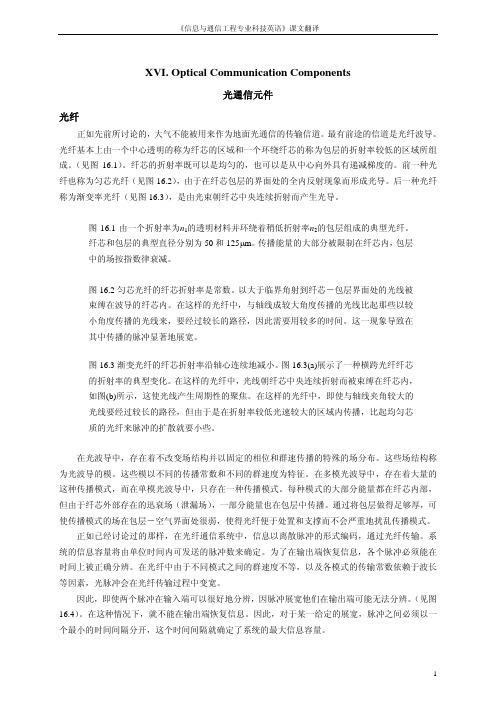
XVI. Optical Communication Components光通信元件光纤正如先前所讨论的,大气不能被用来作为地面光通信的传输信道。
最有前途的信道是光纤波导。
光纤基本上由一个中心透明的称为纤芯的区域和一个环绕纤芯的称为包层的折射率较低的区域所组成。
(见图16.1)。
纤芯的折射率既可以是均匀的,也可以是从中心向外具有递减梯度的。
前一种光纤也称为匀芯光纤(见图16.2),由于在纤芯包层的界面处的全内反射现象而形成光导。
后一种光纤称为渐变率光纤(见图16.3),是由光束朝纤芯中央连续折射而产生光导。
图16.1由一个折射率为n1的透明材料并环绕着稍低折射率n2的包层组成的典型光纤。
纤芯和包层的典型直径分别为50和125μm。
传播能量的大部分被限制在纤芯内,包层中的场按指数律衰减。
图16.2匀芯光纤的纤芯折射率是常数。
以大于临界角射到纤芯-包层界面处的光线被束缚在波导的纤芯内。
在这样的光纤中,与轴线成较大角度传播的光线比起那些以较小角度传播的光线来,要经过较长的路径,因此需要用较多的时间。
这一现象导致在其中传播的脉冲显著地展宽。
图16.3渐变光纤的纤芯折射率沿轴心连续地减小。
图16.3(a)展示了一种横跨光纤纤芯的折射率的典型变化。
在这样的光纤中,光线朝纤芯中央连续折射而被束缚在纤芯内,如图(b)所示,这使光线产生周期性的聚焦。
在这样的光纤中,即使与轴线夹角较大的光线要经过较长的路径,但由于是在折射率较低光速较大的区域内传播,比起均匀芯质的光纤来脉冲的扩散就要小些。
在光波导中,存在着不改变场结构并以固定的相位和群速传播的特殊的场分布。
这些场结构称为光波导的模。
这些模以不同的传播常数和不同的群速度为特征。
在多模光波导中,存在着大量的这种传播模式,而在单模光波导中,只存在一种传播模式。
每种模式的大部分能量都在纤芯内部,但由于纤芯外部存在的迅衰场(泄漏场),一部分能量也在包层中传播。
通过将包层做得足够厚,可使传播模式的场在包层-空气界面处很弱,使得光纤便于处置和支撑而不会严重地扰乱传播模式。
通信工程专业英语翻译

通信工程专业英语翻译Part B1. Desktop systems allow remote users to share CAD files as well as other office documents created in spreadsheets, word processors, presentation packages, etc.桌面系统让远程用户能够共享计算机辅助设计档案与其他一些制作在电子表格、文字处理器、图像程序包中的办公室文件。
3. At the World’s Fair 1964, AT&T demonstrated its first videophone, a desktop (or countertop)configuration that provided low quality images using analog technology.在1964年的世界博览会上,美国电话电报公司展示了其首款可视电话-一种桌面(或者台式)机器。
由于使用的是模拟技术,它提供的图像质量不高。
5. Today, systems level implementers have to live within the constraints of standards-based compression algorithms, since standards are the foundation for interoperability, which in the communications field is absolutely necessary.如今,系统水平的操作者不得不受限于基于标准的压缩算法,由于标准时互用性的基础。
而在通行领域,互用性是极其重要的。
Part A1. The word “multimedia”is being used to describe a mixture of hardware, software and applications, with a consequent confusion in people’s mind as to what it is.“多媒体”一词被用来描述硬件、软件及应用的混合体。
通信工程专业英语课文翻译

Technology of Modern CommunicationText A: BluetoothBluetooth wireless technology is a short-range communications technology intended to replace the cables connecting portable(轻便的)and fixed devices while maintaining high levels of security.The key features of Bluetooth technology are robustness(稳健), low power, and low cost .The Bluetooth specification defines a uniform structure for a wide range of devices to connect and communicate with each other.蓝牙无线技术是一种小范围无线通信技术,旨在保持高安全级的基础上,在便携式设备与固定设备之间实现无线连接。
蓝牙技术的主要特点是稳健,低功耗和低成本。
蓝牙规范定义了一个统一的结构,适用范围广的设备连接并相互沟通。
Bluetooth technology has achieved global acceptance such that any Bluetooth enable device, almost everywhere in the world, can connect to other Bluetooth enabled devices in proximity. Bluetooth enabled electronic devices connect and communicate wirelessly through short-range, ad hoc(特别)networks known as piconets Each device can simultaneously communicate with up to seven other devices within a single piconet. Each device can also belong to several piconets simultaneously. Piconets are established dynamically and automatically as Bluetooth enabled devices enter and leave radio proximity.蓝牙技术已取得全球认可,使得任何支持蓝牙的设备,几乎在世界各地,可以连接到其他支持蓝牙的邻近装置。
信息与通信工程专业科技英语翻译9
IX. Multiple Access Techniques: FDMA, TDMA and CDMA复用技术:频分复用、时分复用、码分复用复用方案用于使许多用户同时使用同一个固定的无线电频带。
在任何无线电系统中分配的带宽总是有限的。
移动无线电话系统的典型总带宽是50MHz,它被分成两半用以提供系统的前向和反向连接。
任何无线网络为了提高用户容量都需要共享频谱。
频分复用(FDMA)、时分复用(TDMA)、码分复用(CDMA)是无线系统中由众多用户共享可用带宽的三种主要方法。
这些方法又有许多扩展和混合技术,例如正交频分复用(OFDM),以及混合时分和频分复用系统。
不过要了解任何扩展技术首先要求对三种基本方法的理解。
频分复用在FDMA中,可用带宽被分为多个较窄的频带。
每一用户被分配一个独特的频带用于发送和接收。
在一次通话中其他用户不能使用同一频带。
每个用户分配到一个由基站到移动电话的前向信道以及一个返回基站的反向信道,每个信道都是一个单向连接。
在每个信道中发送信号是连续的,以便进行模拟通信。
FDMA信道的带宽一般较小(30kHz),每个信道只支持一个用户。
FDMA作为大多数多信道系统的一部分用于初步分割分配到的宽频带。
将可用带宽分配给几个信道的情况见图9.1和图9.2。
时分复用通过分配给每一个用户一个时隙以便在其中发送或接收,TDMA将可用频谱分成多个时隙。
图9.3显示如何以一种循环复用的方式把时隙分配给用户,每个用户每帧分得一个时隙。
TDMA以缓冲和爆发方式发送数据。
因此每个信道的发射是不连续的。
待发送的输入数据在前一帧期间被缓存,在分配给该信道的时隙中以较高速率爆发式发送出去。
TDMA不能直接传送模拟信号因为它需要使用缓冲,因而只能用于传输数字形式的数据。
由于通常发射频率很高,TDMA会受到多径效应的影响。
这导致多径信号引起码间干扰。
TDMA一般与FDMA结合使用,将可用的全部带宽划分为若干信道。
通信工程专业外语 unit13原文与翻译
Unit 13Comparison between GSM and CDMA GSM与CDMA之比较Using CDMA/FDD technology, subscribers of CDMA cellular mobile communication system can transmit their information simultaneously through the same channel. On the other hand, the GSM system adopts TDMA/FDD method to transmit and distinguish information from different GSM mobile stations. In addition, in favor of QCELP arithmetic, RAKE receiver, power control and soft switching etc., CDMA shows more advantages in its system performance than the GSM, such as greater anti-interference capability, bigger system capacity, higher successful connection ratio, fewer off-line chances, low probability of intercept(LPI), and so on.使用码分多址/频分双工技术,用户的蜂窝移动通信系统的传输信息的同时,通过同样的渠道。
另一方面,该系统采用时分多址/频分双工传输的方法和识别信息从不同的移动台。
此外,有利于中国电信集团广州研发中心算术,耙式接收器,功率控制和软开关等,显示出更多的优势在码分多址系统性能比,如更高的抗干扰能力,更大的系统容量,连接成功率较高,离线的机会少,低截获概率(低截获概率),等。
电子信息与通信工程专业英语课文翻译21

电子信息与通信工程专业英语课文翻译2.1————————————————————————————————作者:————————————————————————————————日期:2电路系统与设计2.1电路和系统1.基础概念电荷和导电性在Bohr的原子理论中(以Niels Bohr命名,1885-1962),电子围绕着质子和种子运动。
在相反极性电子和质子的电荷之间的吸引力使得原子连在一起。
具有同种电荷的粒子将会相互排斥。
电荷的测量值是库伦。
一个单独的电子或质子的电荷远小于一库伦,一个电子是—1.6×1(-19)库伦,一个质子是1.6×10(-19)库伦。
自然表明,只有一个质子的电荷和电子是反极性的。
这里没有固有的负极电子,只是很容易被称为正极的和质子负极的。
原子不同形态的电子有不同程度的自由度。
一些材料的形态,例如金属,最外层的电子受到很弱的约束使得它们能够在室温热能量的影响下载原子空间中自由运动。
因为这些事实上不受约束的电子式可以在自身的原子中自由运动的,也可以漂浮在临近的原子周围的空间中,它们常被称为自由电子。
在其他一些形态的材料中如玻璃,它的原子的电子几乎不能自由移动。
当外部的力量如物理摩擦时,能够强迫一些电子离开它们自身的原子,移动到其他物质的原子中,它们在材料的原子中不能很容易的移动。
这些在材料中电子的移动性的关系被认为是电子的导电性。
导电性决定于材料中原子的形态(每个原子核的栀子数,决定他的化学特性。
)和原子是怎样与另一个原子连接在一起的。
有高度灵活电子的材料(许多自由电子)被称为导体,而有很少灵活电子的材料(几乎或是没有自由电子)的材料被称为绝缘体。
必须知道,一些物质的化学特性将在不同环境下改变。
例如,玻璃在室温下是一个非常好的绝缘体,但当把它加热到相当高的温度时它就变成一个导体。
气体如空气,常态下是绝缘体,但如果加热到很高的温度也会变成导体。
大部分金属被加热时导电性能会下降,而被冷制的时候导电性能会更好。
通信工程专业英语翻译

Fiberto the Home(光纤到家)光纤到家(FTTH)是一个住宅的通信基础设施,光纤电缆运行所有的方式向用户。
经过多年的期待,各种部署光纤到户是最后出现在美国各地的社区虽然光纤到户是一种技术,它为本地接入市场的竞争动态有趣的影响。
光纤到户网络可以提供的带宽比目前现有的宽带技术的许多倍。
今天似乎每个人都想要的高速数据,可靠的语音服务,高质量的视频。
无论这些服务是由数字用户线(DSL)交付,电缆调制解调器或无线架构是微不足道的,只要服务是快速和可靠的。
FTTH使运营商能够提供多种通信和娱乐服务,包括高速互联网接入,广播,有线电视,直播卫星(DBS)电视,互动的双向视频服务。
此外,一个FTTH解决方案基于波分复用(WDM),允许更多的灵活性和适应性,进一步支持服务。
进一步支持服务的适应性。
在FTTH系统,在前端设备或是连接到公共交换电话网络(PSTN)唱DS-1和连接到A TM、以太网接口。
视频服务从有线电视(CATV)进入系统的头端或来至卫星饲料。
所有这些信号,然后合并成采用WDM技术单光纤传输通过无源光分路器的最终用户。
分路器通常放在离中心局(CO)约3000英尺。
分流比的范围可以从2到32的用户并没有在网络中使用任何活性成分。
然后将信号送到3个000英尺的家在一个单一的纤维。
一个理想的F TTH系统必须提供的所有服务用户的能力支付,如电路交换电话,视频服务、高速数据广播。
在家里,光信号转换成电信号的光电转换器(OEC)。
OEC把信号分成由最终用户所需的服务。
理想情况下,其将有标准的用户界面,提供所需的服务不集LL D 盒。
这些接口包括电话RJ11插孔,RJ45接口的高速数据,和75欧姆同轴电缆端口的有线电视和卫星直播业务。
电子信息与通信工程专业英语课文翻译3.2

3.2 数字信号处理1 简介数字信号处理是21世纪用于科学和工程领域最强大的技术之一,它使一个广阔的领域发生了革命性的改变:通信,医学影像,雷达或声纳,高保真音乐复制,石油勘测,以上只是列举几个。
每个领域都有它自身独特的算法(algorithm),数学运算(mathematic),专用工艺(specialized technique)。
数字信号处理在计算机科学方面有别于其他领域,因为他采用一种特殊的数据类型:信号。
现代社会中,我们的身边充满各种类型的信号。
有些信号是天然形成的,但大多数是人为制造的。
有些信号是必要的(语音),有些是宜人的(音乐),而有些信号在某个特定的场合是不需要或不必要的。
在大多数情况下,这些信号来源于人对真实世界的感觉,比如地震的震动,视觉图像,声音波形等。
数字信号处理是一种数学工具,是一种用来处理那些将上述信号转换成数字形式后的信号的算法和技术。
这包括一系列目的,如:视觉图像的优化处理,语音识别和生成,数据压缩存储和传输等。
在工程范围内,信号是信息的载体,既有益又有害。
信号处理中最简单的形式是从一连串相互矛盾的信息中提取和增强有用信息。
信息的有用和无用往往只是主管和客观的区别。
因此信号处理往往依赖于应用程序。
傅里叶分析和滤波器设计是信号处理时常用的方法。
他们的原则简单描述如下。
2 傅里叶分析函数的傅里叶表示,即将函数表示成正弦和余弦信号的叠加,这种方法已经广泛用于微分方程的解析法和数值法求解过程以及通信信号的分析和处理。
傅里叶变换的效用在于它能够在时域范围内分析它的频率内容。
变换的第一步是将时域上的函数转换为时域表示。
(The transform works by first translating a function in the time domain into a function in the frequency domain)。
然后就可以分析信号的频率内容了。
因为变换函数的傅里叶系数代表各个正弦和余弦函数在各自对应频率区间的分配。
通信工程专业英语翻译
通信一班杨林14112300954JXTA is a more than 20 years’hard-working work of Bill Joy, who is the chief scientist of Sun. JXTA technology is aplatform of network’s programming and computing, which is used to solve the modern distributed computing problems especially peer to peer problems. XTA’s research projectwill provide a new framework which canmake users more convenient to visit the PC, which is connected with the Internet, and thus further develop the space of Internet. At the same time, JXTA is also the continuation of Sun’s strategy ‘One Internet’. And JXTA will take a more positiveway to compete with the Microsoft’s Net strategy and Hailstorm’s plans.JXTA treaty defines a set of six protocols based on XML, which provides standardizedways fo r the nodes’ self-organizing into a node group, publishing and findingnotes resources, communicating and mutual monitoring. Firstly, The Endpoint Routing Protocol is used for founding node’s routing and sending message to the other node, and run across the potential of firewalls and network. Secondly, Rendezvous Protocol is used for spreading newsin the node group. Thirdly, Peer Resolver Protocolis used to send one or more notes to send common queries, and receives the response of query. Fourthly, Peer Discovery Protocol is used to release and find resources andinformation. Fifthly, Peer Information Protocolis used to obtain Information from other nodes.Finally, Peer Binding Protocol is used to allowa node to another node to set up virtual communication channels between multiple nodes or pipe.Compared to the general communication model, P2P has many advantages, but it also has a lot of problems to be solved. On the one hand, each Peer in P2P is active participants, but, in order to increase network performance, we need more peers’ participation.So, it will enlarge network, and it is a more complicated engineering to manage the network. On the other hand, the P2P protocol needs more interaction than the traditional ones, such as peer’s entering and quitt ing the network. And these factors will cause some negative influences to the function of the network.。
通信工程专业英语论文
通信工程专业英语论文外文翻译(原文)The General Situation of AT89C51The AT89C51 is a low-power, high-performance CMOS 8-bit microcomputer with 4K bytes of Flash Programmable and Erasable Read Only Memory (PEROM) and 128 bytes RAM. The device is manufactured using Atmel’s high density nonvolatilememory technology and is compatible with the industry standard MCS-51?instruction set and pin out. The chip combines a versatile 8-bit CPU with Flash on a monolithic chip; the Atmel AT89C51 is a powerful microcomputer which provides a highly flexible and cost effective solution to many embedded control applications.Features:• Compatible with MCS-51? Products• 4K Bytes of In-System Reprogrammable Flash Memory• Endurance: 1,000 Write/Erase Cycles• Fully Static Operatio n: 0 Hz to 24 MHz• Three-Level Program Memory Lock• 128 x 8-Bit Internal RAM• 32 Programmable I/O Lines• Two 16-Bit Timer/Counters• Six Interrupt Sources• Programmable Serial Channel• Low Power Idle and Power Down ModesThe AT89C51 provides the following standard features: 4K bytes of Flash, 128 bytes of RAM, 32 I/O lines, two 16-bit timer/counters, a five vector two-level interrupt architecture, a full duplex serial port, on-chip oscillator and clock circuitry. In addition, the AT89C51 is designed with static logic for operation down to zero frequency and supports two software selectable power saving modes. 1外文翻译(原文)The Idle Mode stops the CPU while allowing the RAM, timer/counters, serial port and interrupt system to continue functioning. The Power Down Mode saves the RAM contents but freezes the oscillator disabling all other chip functions until the next hardware reset.Block DiagramPin Description:VCC Supply voltage.GND Ground.Port 0:Port 0 is an 8-bit open drain bidirectional I/O port. As an output port eachpin can sink eight TTL inputs. When 1s are written to port 0 pins, the pins can be used as high impedance inputs. (Sink/flow) Port 0 may also be configured to be the multiplexed low order address/data bus during accesses to external program and data memory. In this mode P0 has 2外文翻译(原文)internal pull-ups.Port 0 also receives the code bytes during Flash programming, and outputs the code bytes during program verification. External pull-ups are required during program verification.Port 1:Port 1 is an 8-bit bidirectional I/O port with internal pull-ups. The Port 1 output buffers can sink/source four TTL inputs. When 1s are written to Port 1 pins they are pulled high by the internal pull-ups and can be used as inputs. As inputs, Port 1 pins that are externally being pulled low will source current (IIL) because of the internal pull-ups.Port 1 also receives the low-order address bytes during Flash programming and verification.Port 2 is an 8-bit bidirectional I/O port with internal pull-ups. The Port 2 Port 2:output buffers can sink/source four TTL inputs. When 1s are written to Port 2 pins they are pulled high by the internal pull-ups and can be used as inputs. As inputs, Port 2 pins that are externally being pulled low will source current (IIL) because of the internal pull-ups.Port 2 emits the high-order address byte during fetches fromexternal program memory and during accesses to external data memory that uses 16-bit addresses (MOVX @ DPTR). In this application it uses strong internal pull-ups when emitting 1s. During accesses to external datamemories that use 8-bit addresses (MOVX @ RI), Port 2 emits the contents of the P2 Special Function Register.Port 2 also receives the high-order address bits and some control signals during Flash programming and verification.Port 3:Port 3 is an 8-bit bidirectional I/O port with internal pull-ups. The Port 3 output buffers can sink/source four TTL inputs. When 1s are written to Port 3 pins they are pulled high by the internal pull-ups and can be used as inputs. As inputs, Port 3 pins that are externally being pulled low will source current (IIL) because of the pull-ups.3外文翻译(原文)Port 3 also serves the functions of various special features of the AT89C51 as listed below:Port 3 also receives some control signals for Flash programming and verification.RST:Reset input. A high on this pin for two machine cycles while the oscillator is running resets the device.ALE/PROG:Address Latch Enable output pulse for latching the low byte of theaddress during accesses to external memory. This pin is also the program pulse input (PROG) during Flash programming.In normal operation ALE is emitted at a constant rate of 1/6 the oscillator frequency, and may be used for external timing or clockingpurposes. Note, however, that one ALE pulse is skipped during each access to external Data Memory.If desired, ALE operation can be disabled by setting bit 0 of SFR location 8EH. With the bit set, ALE is active only during a MOVX or MOVC instruction. Otherwise, the pin is weakly pulled high. Setting the ALE-disable bit has no effect if the microcontroller is in externalexecution mode.PSEN:Program Store Enable is the read strobe to external program memory. When the AT89C51 is executing code from external program memory, PSEN is activated twice each machine cycle, except that two PSEN activations are skipped during each access to external data memory.4外文翻译(原文)EA/VPP:External Access Enable. EA must be strapped to GND in orderto enable the device to fetch code from external program memorylocations starting at 0000H up to FFFFH. Note, however, that if lock bit 1(LB1) is programmed, EA will be internally latched (fasten with a latch) on reset.EA should be strapped to VCC for internal program executions.This pin also receives the 12-volt programming enable voltage(VPP) during Flashprogramming, for parts that require 12-volt VPP.XTAL1:Input to the inverting oscillator amplifier and input to the internal clock operating circuit.XTAL2:Output from the inverting oscillator amplifier.Oscillator Characteristics:XTAL1 and XTAL2 are the input and output, respectively, of an inverting amplifier which can be configured for use as an on-chip oscillator, as shown in Figure 1. Either a quartz crystal or ceramic resonator may be used. To drive the device from an external clock source, XTAL2 should be left unconnected while XTAL1 is driven as shown in Figure 2. There are no requirements on the duty cycle of the external clock signal, since the input to the internal clockingcircuitry is through a divide-by-two flip-flop, but minimum and maximum voltage high and low times specifications must be observed.Idle Mode:In idle mode, the CPU puts itself to sleep while all theon chip peripherals remain active. The mode is invoked by software. The content of the on-chip RAM and all the special functions registersremain unchanged during this mode. The idle mode can be terminated byany enabled interrupt or by a hardware reset.It should be noted that when idle is terminated by a hard ware reset, the device normally resumes program execution, from where it left off,up to two machine cycles before the internal reset algorithm takes control. On-chip hardware inhibits access to internal RAM in this event, but access to the port pins is not inhibited. To eliminate thepossibility of an unexpected write to a port pin when Idle is terminated by reset, the instruction following the one that invokes Idle 5 外文翻译(原文)should not be one that writes to a port pin or to external memory.Power Down ModeIn the power down mode the oscillator is stopped, and theinstruction that invokes power down isthe last instruction executed. The on-chip RAM and Special Function Registers retain their values until the power down mode is terminated. The only exit from power down is a hardware reset. Reset redefines the SFRs but does not change the on-chip RAM. The reset should not be activated before VCC is restored to its normal operating level and must be held active long enough to allow the oscillator to restart and stabilize.Program Memory Lock BitsOn the chip are three lock bits which can be left unprogrammed (U)or can be programmed (P) to obtain the additional features listed in the table below:When lock bit 1 is programmed, the logic level at the EA pin is sampled and latched during reset. If the device is powered up without a reset, the latch initializes to a random value, and holds that value until reset is activated. It is6外文翻译(原文)necessary that the latched value of EA be in agreement with the current logic level at that pin in order for the device to function properly.Programming the Flash:The AT89C51 is normally shipped with the on-chip Flashmemory array in the erased state (that is, contents = FFH) and ready to be programmed. The programming interface accepts either a high-voltage (12-volt) or alow-voltage (VCC) program enable signal. The low voltage programming mode provides a convenient way to program the AT89C51 inside the user’s system, whilethe high-voltage programming mode is compatible with conventional third party Flash or EPROM programmers.The AT89C51 is shipped with either the high-voltage or low-voltage programming mode enabled. The respective top-side marking and device signatureThe AT89C51 code memory array is programmed byte-bybyte in either programming mode. To program any nonblank byte in the on-chip Flash Programmable and Erasable Read Only Memory, the entire memory must be erased using the Chip Erase Mode.Programming Algorithm: Before programming the AT89C51, the address, data and control signals should be set up according to the Flash programming mode table and Figures 3 and 4. To program the AT89C51, take the following steps.1. Input the desired memory location on the address lines.2. Input the appropriate data byte on the data lines.3. Activate the correct combination of control signals.4. Raise EA/VPP to 12V for the high-voltage programming mode.7外文翻译(原文)5. Pulse ALE/PROG once to program a byte in the Flash array or thelock bits. The byte-write cycle is self-timed and typically takes nomore than 1.5 ms. Repeat steps 1 through 5, changing the address anddata for the entire array or until the end of the object file is reached.Data Polling: The AT89C51 features Data Polling to indicate the endof a write cycle. During a write cycle, an attempted read of the lastbyte written will result in the complement of the written datum on PO.7. Once the write cycle has been completed, true data are valid on all outputs, and the next cycle may begin. Data Polling may begin any time after a write cycle has been initiated.Ready/Busy: The progress of byte programming can also be monitoredby the RDY/BSY output signal. P3.4 is pulled low after ALE goes high during programming to indicate BUSY. P3.4 is pulled high again when programming is done to indicate READY.Program Verify: If lock bits LB1 and LB2 have not been programmed,the programmed code data can be read back via the address and data lines for verification. The lock bits cannot be verified directly.Verification of the lock bits is achieved by observing that theirfeatures are enabled.Chip Erase: The entire Flash Programmable and Erasable Read Only Memory array is erased electrically by using the proper combination of control signals and byholding ALE/PROG low for 10 ms. The code array is written with all “1”s. The chiperase operation must be executed before the code memory can be re-programmed.Reading the Signature Bytes: The signature bytes are read by the same procedure asa normal verification of locations 030H, 031H, and 032H, except that P3.6 and P3.7must be pulled to a logic low. The values returned are as follows.(030H) = 1EH indicates manufactured by Atmel(031H) = 51H indicates 89C51(032H) = FFH indicates 12V programming(032H) = 05H indicates 5V programming8外文翻译(原文)Programming InterfaceEvery code byte in the Flash array can be written and the entire array can be erasedby using the appropriate combination of control signals. The write operation cycle isselftimed and once initiated, will automatically time itself to completion.9单片机温度控制系统中英文翻译资料AT89C51的概况AT89C51是美国ATMEL公司生产的低电压,高性能CMOS8位单片机,片内含4Kbytes的快速可擦写的只读程序存储器(PEROM)和128 bytes 的随机存取数据存储器(RAM),器件采用ATMEL公司的高密度、非易失性存储技术生产,兼容标准MCS-51产品指令系统,片内置通用8位中央处理器(CPU)和flish 存储单元,功能强大AT89C51单片机可为您提供许多高性价比的应用场合,可灵活应用于各种控制领域。
信息与通信工程专业科技英语课文翻译4

通信工程中英文翻译
Combined Adaptive Filter with LMS-Based AlgorithmsBoˇ zo Krstaji´ c, LJubiˇ sa Stankovi´ c,and Zdravko Uskokovi´Abstract: A combined adaptive filter is proposed. It consists of parallel LMS-based adaptive FIR filters and an algorithm for choosing the better among them. As a criterion for comparison of the considered algorithms in the proposed filter, we take the ratio between bias and variance of the weighting coefficients. Simulations results confirm the advantages of the proposed adaptive filter. Keywords: Ad aptive filter, LMS algorithm, Combined algorithm,Bias and variance trade-off 1.IntroductionAdaptive filters have been applied in signal processing and control, as well as in many practical problems, [1, 2]. Performance of an adaptive filter depends mainly on the algorithm used for updating the filter weighting coefficients. The most commonly used adaptive systems are those based on the Least Mean Square (LMS) adaptive algorithm and its modifications (LMS-based algorithms).The LMS is simple for implementation and robust in a number of applications [1–3]. However, since it does not always converge in an acceptable manner, there have been many attempts to improve its performance by the appropriate modifications: sign algorithm (SA) [8], geometric mean LMS (GLMS) [5], variable step-size LMS(VS LMS) [6, 7].Each of the LMS-based algorithms has at least one parameter that should be defined prior to the adaptation procedure (step for LMS and SA; step and smoothing coefficients for GLMS; various parameters affecting the ste p for VS LMS). These parameters crucially influence the filter output during two adaptation phases:transient and steady state. Choice of these parameters is mostly based on some kind of trade-off between the quality of algorithm performance in the mentioned adaptation phases.We propose a possible approach for the LMS-based adaptive filter performance improvement. Namely, we make a combination of several LMS-based FIR filters with different parameters, and provide the criterion for choosing the most suitable algorithm for different adaptation phases. This method may be applied to all the LMS-based algorithms, although we here consider only several of them.The paper is organized as follows. An overview of the considered LMS-based algorithms is given in Section 2.Section 3 proposes the criterion for evaluation and combination of adaptive algorithms. Simulation results are presented in Section 4.2. LMS based algorithmsLet us define the input signal vector T k N k x k x k x X )]1()1()([+--=Λand vector ofweighting coefficients a s T N k k W k W k W W )]()()([110-=Λ.The weighting coefficients vectorshould be calculated according to:}{21k k k k X e E W W μ+=+ (1)where µ is the algorithm step, E{·} is the estimate of the expected value and k T k k k X W d e -=isthe error at the in-stant k,and dk is a reference signal. Depending on the estimation of expected value in (1), one defines various forms of adaptive algorithms: the LMS {}()k k k k X e X e E =,the GLMS {}()()∑=--≤<-=k i ik i k i k k a X e a aX e E 010,1, and the SA {}()()k k k k e sign X X e E =,[1,2,5,8] .The VS LMS has the same form as the LMS, but in the adaptation the step µ(k) is changed [6, 7].The considered adaptive filtering problem consists in trying to adjust a set of weightingcoefficients so that the system output,k T k k X W y =, tracks a reference signal, assumed as k k Tk k n X W d +=*,where k n is a zero mean Gaussian noise with the variance 2n σ,and *k W is the optimal weight vector (Wiener vector). Two cases will be considered:W W k =* is a constant (stationary case) and *k W is time-varying (nonstationary case). In nonstationary case the unknown system parameters( i.e. the optimal vector *k W )are time variant. It is often assumed thatvariation of *k W may be modeled as K k k Z W W +=+**1 is the zero-mean random perturbation,independent on k X and k n with the autocorrelation matrix []I Z Z E G Z T k k 2σ==.Note that analysis for the stationary case directly follows for 02=Z σ.The weighting coefficient vector converges to the Wiener one, if the condition from [1, 2] is satisfied.Define the weighting coefficientsmisalignment, [1–3],*k k k W W V -=. It is due to both the effects of gradient noise (weighting coefficients variations around the average value) and the weighting vector lag (difference between the average and the optimal value), [3]. It can be expressed as:()()()()*k k k k k W W E W E W V -+-=, (2)According to (2), the ith element of k V is:(3)where ()()k W bias i is theweighting coefficient bias and ()k i ρ is a zero-mean random variable with the variance 2σ.Thevariance depends on the type of LMS-based algorithm, as well as on the external noise variance()()()()()()()()()()()()k k W bias k W E k W k W k W E k V i i i i i i i ρ+=-+-=*2n σ.Thus, if the noise variance is constant or slowly-varying,2σ is time invariant for a particular LMS-based algorithm. In that sense, in the analysis that follows we will assume that 2σ depends only on the algorithm type, i.e. on its parameters.An important performance measure for an adaptive filter is its mean square deviation (MSD) of weighting coefficients. For the adaptive filters, it is given by, [3]:[]k T k k V V E MSD ∞→=lim . 3. Combined adaptive filterThe basic idea of the combined adaptive filter lies in parallel implementation of two or more adaptive LMS-based algorithms, with the choice of the best among them in each iteration [9]. Choice of the most appropriate algorithm, in each iteration, reduces to the choice of the best value for the weighting coefficients. The best weighting coefficient is the one th at is, at a given instant, the closest to the corresponding value of the Wiener vector.Let ()q k W i , be the i −th weighting coefficient for LMS-based algorithm with the chosen parameter q at an instant k. Note that one may now treat all the algorithms in a unified way (LMS: q ≡ µ,GLMS: q ≡ a,SA:q ≡ µ). LMS-based algorithm behavior is crucially dependent on q. In each iteration there is an optimal value qopt , producing the best performance of the adaptive al- gorithm. Analyze now a combined a daptive filter, with several LMS-based algorithms of the same type, but with different parameter q.The weighting coefficients are random variables distributed around the ()k W i *,with()()q k W bias i ,and the variance 2q σ, related by [4, 9]:()()()()q i i i q k W bias k W q k W κσ≤--,,*, (4)where (4) holds with the probability P(κ), dependent on κ. For example, for κ = 2 and a Gaussian distribution,P(κ) = 0.95 (two sigma rule).Define the confidence inte rvals for ()]9,4[,,q k W i :()()()[]q i q i i q k W k q k W k D κσσ2,,2,+-= (5)Then, from (4) and (5) we conclude that, as long as ()()q i q k W bias κσ<,,()()k D k W i i ∈*, independently on q. This means that, for small bias, the confidence inte rvals, for different s q ' of the same LMS-based algorithm, of the same LMS-based algorithm, intersect. When, on the other hand, the bias becomes large, then the central positions of the intervals for different s q ' are far apart, and they do not intersect.Since we do not have apriori information about the ()()q k W bias i ,,we will use a specific statistical approach to get the criterion for the choice of adaptive algorithm, i.e. for the values of q.The criterion follows from the trade-off condition that bias and variance are of the same order of magnitude, i.e.()()[]4,,q i q k W bias κσ≅.The proposed combined algorithm (CA) can now be summarized in the following steps: Step 1. Calculate ()q k W i ,for the algorithms with different s q 'from the predefined set {}K ,,2q q Q i =.Step 2. Estimate the variance 2qσ for each considered algorithm. Step 3. Check if ()k D i intersect for the considered algorithms. Start from an algorithm with largest value of variance, and go toward the ones with smaller values of variances. According to(4), (5) and the trade-off criterion, this check reduces to the check if()()()ql qm l i m i q k W q k W σσκ+<-2,, (6)is satisfied, where Q q q l m ∈,,and the following relation holds:Q q q h ql qh qm h ∉⇒>>∀,:222σσσ.If no ()k D i intersect (large bias) choose the algorithm with largest value of variance. If the ()k D i intersect, the bias is already small. So, check a new pair of weighting coefficients or, if that is the last pair, just choose the algorithm with the smallest variance. First two intervals that do not intersect mean that the proposed trade-off criterion is achieved, and choose the algorithm with large variance.Step 4. Go to the next instant of time.The smallest number of elements of the set Q is L =2. In that case, one of the s q 'should provide good tracking of rapid variations (the largest variance), while the other should provide small variance in the steady state. Observe that by adding few more s q ' between these two extremes, one may slightly improve the transient behavior of the algorithm.Note that the only unknown values in (6) are the variances. In our simulations we estimate 2qσ as in [4]: ()()()2675.0/1--=k W k W median i i q σ, (7)for k = 1, 2,... , L and 22qZ σσ<<. The alternative way is to estimate 2n σ as:∑=≈T i i n e T 1221σ,for x (i ) = 0. (8) Expressions relating 2n σ and 2q σ in steady state, for different types of LMS-based algorithms, are known from literature. For the standard LMS algorithm in steady state, 2n σ and2q σ are related 22nq q σσ=,[3]. Note that any other estimation of 2q σis valid for the proposed filter.Complexity of the CA depends on the constituent algorithms (Step 1), and on the decision algorithm (Step 3).Calculation of weighting coefficients for parallel algorithms does not increase the calculation time, since it is performed by a parallel hardware realization, thus increasing the hardware requirements. The variance estimations (Step 2), negligibly contribute to the increase of algorithm complexity, because they are performed at the very beginning of adaptation and they are using separate hardware realizations. Simple analysis shows that the CA increases the number of operations for, at most, N(L −1) additions and N (L −1) IF decisions, and needs some additional hardware with respect to the constituent algorithms.4.Illustration of combined adaptive filterConsider a system identification by the combination of two LMS algorithms with different steps. Here, the parameter q is μ,i.e. {}{}10/,,21μμ==q q Q .The unknown system has four time-invariant coefficients,and the FIR filters are with N = 4. We give the average mean square deviation (AMSD ) for both individual algorithms, as well as for their combination,Fig. 1(a). Results are obtained by averaging over 100 independent runs (the Monte Carlo method), with μ = 0.1. The reference dk is corrupted by a zero-mean uncorrelatedGaussian noise with 2n σ= 0.01 and SNR = 15 dB, and κ is 1.75. In the first 30 iterations thevariance was estimated according to (7), and the CA picked the weighting coefficients calculated by the LMS with μ.As presented in Fig. 1(a), the CA first uses the LMS with μ and then, in the steady state, the LMS with μ/10. Note the region, between the 200th and 400th iteration,where the algorithm can take the LMS with either stepsize,in different realizations. Here, performance of the CA would be improved by increasing the number of parallel LMS algorithms with steps between these two extrems.Observe also that, in steady state, the CA does not ideally pick up the LMS with smaller step. The reason is in the statistical nature of the approach.Combined adaptive filter achieves even better performance if the individual algorithms, instead of starting an iteration with the coefficient values taken from their previous iteration, take the ones chosen by the CA. Namely, if the CA chooses, in the k -th iteration, the weighting coefficient vector P W ,theneach individual algorithm calculates its weighting coefficients in the (k +1)-th iteration according to:{}k k p k X e E W W μ21+=+(9)Fig. 1. Average MSD for considered algorithms.Fig. 2. Average MSD for considered algorithms.Fig. 1(b) shows this improvement, applied on the previous example. In order to clearly compare the obtained results,for each simulation we calculated the AMSD . For the first LMS (μ) it was AMSD = 0.02865, for the second LMS (μ/10) it was AMSD = 0.20723, for the CA (CoLMS) it was AMSD = 0.02720 and for the CA with modification (9) it was AMSD = 0.02371.5. Simulation resultsThe proposed combined adaptive filter with various types of LMS-based algorithms is implemented for stationary and nonstationary cases in a system identification setup.Performanceof the combined filter is compared with the individual ones, that compose the particularcombination.In all simulations presented here, the reference dk is corrupted by a zero-mean uncorrelatedGaussian noise with 1.02=n σand SNR = 15 dB. Results are obtained by averaging over 100independent runs, with N = 4, as in the previous section.(a) Time varying optimal weighting vector: The proposed idea may be applied to the SA algorithms in a nonstationary case. In the simulation, the combined filter is composed out of three SA adaptive filters with different steps, i.e. Q = {μ, μ/2, μ/8}; μ = 0.2. The optimal vectors is generated according to the presented model with 001.02=Z σ,and with κ = 2. In the first 30 iterations the variance was estimated according to (7), and CA takes the coefficients of SA with μ (SA1).Figure 2(a) shows the AMSD characteristics for each algorithm. In steady state the CA does not ideally follow the SA3 with μ/8, because of the nonstationary problem nature and a relatively small difference between the coefficient variances of the SA2 and SA3. However,this does not affect the overall performance of the proposed algorithm. AMSD for each considered algorithm was: AMSD = 0.4129 (SA1,μ), AMSD = 0.4257 (SA2,μ/2), AMSD = 1.6011 (SA3, μ/8) and AMSD = 0.2696(Comb).(b) Comparison with VS LMS algorithm [6]: In this simulation we take the improved CA (9) from 3.1, and compare its performance with the VS LMS algorithm [6], in the case of abrupt changes of optimal vector. Since the considered VS LMS algorithm[6] updates its step size for each weighting coefficient individually, the comparison of these two algorithms is meaningful. All the parameters for the improved CA are the same as in 3.1. For the VS LMS algorithm[6], the relevant parameter values are the counter of sign change m 0 = 11,and the counter of sign continuity m 1 = 7. Figure 2(b)shows the AMSD for the compared algorithms, where one can observe the favorable properties of the CA, especially after the abrupt changes. Note that abrupt changes are generated by multiplying all the system coefficients by −1 at the 2000-th iteration (Fig. 2(b)). The AMSD for the VS LMS was AMSD = 0.0425, while its value for the CA (CoLMS) was AMSD = 0.0323.For a complete comparison of these algorithms we consider now their calculation complexity, expressed by the respective increase in number of operations with respect to the LMS algorithm. The CA increases the number of requres operations for N additions and N IF decisions.For the VSLMS algorithm, the respective increase is: 3N multiplications, N additions, and at least 2N IF decisions.These values show the advantage of the CA with respect to the calculation complexity.6. ConclusionCombination of the LMS based algorithms, which results in an adaptive system that takes the favorable properties of these algorithms in tracking parameter variations, is proposed.In the course of adaptation procedure it chooses better algorithms, all the way to the steady state when it takes the algorithm with the smallest variance of the weighting coefficient deviations from the optimal value.Acknowledgement. This work is supported by the Volkswagen Stiftung, Federal Republic of Germany.References[1] Widrow, B.; Stearns, S.: Adaptive Signal Processing. Prentice-Hall, Inc. Englewood Cliffs, N.J. 07632.[2] Alexander, S. T.: Adaptive Signal Processing –Theory and Applications. Springer-Verlag, New York 1986.[3] Widrow, B.; McCool, J. M.; Larimore, M. G.; Johnson, C. R.:Stationary and Nonstationary Learning Characteristics of the LMS Adaptive Filter. Proc. IEEE 64 (1976) 1151–1161.[4] Stankovic, L. J.; Katkovnik, V.: Algorithm for the instantaneous frequency estimation using time-frequency distributions with variable window width. IEEE SP. Letters 5 (1998), 224–227. [5] Krstajic, B.; Uskokovic, Z.; Stankovic, Lj.: GLMS Adaptive Algorithm in Linear Prediction. Proc. CCECE’97 I, pp. 114–117, Canada, 1997.[6] Harris, R. W.; Chabries, D. M.; Bishop, F. A.: A Variable Step (VS) Adaptive Filter Algorithm. IEEE Trans. ASSP 34 (1986),309–316.[7] Aboulnasr, T.; Mayyas, K.: A Robust Variable Step-Size LMSType Algorithm: Analysis and Simulations. IEEE Trans. SP 45 (1997), 631–639.[8] Mathews, V. J.; Cho, S. H.: Improved Convergence Analysis of Stochastic Gradient Adaptive Filters Using the Sign Algorithm. IEEE Trans. ASSP 35 (1987), 450–454.[9] Krstajic, B.; Stankovic, L. J.; Uskokovic, Z.; Djurovic, I.:Combined adaptive system for identification of unknown systems with varying parameters in a noisy enviroment. Proc. IEEE ICECS’99, Phafos, Cyprus, Sept. 1999.()()k W bias i 是加权系数的偏差,()k i ρ与方差2σ是零均值的随机变量差,它取决于LMS 的算法类型,以及外部噪声方差2n σ。
通信工程专业英语翻译
Unit 6Part B1. Desktop systems allow remote users to share CAD files as well as other office documents created in spreadsheets, word processors, presentation packages, etc.桌面系统让远程用户能够共享计算机辅助设计档案以及其他一些制作在电子表格、文字处理器、图像程序包中的办公室文件。
3. At the World’s Fair 1964, AT&T demonstrated its first videophone, a desktop (or countertop)configuration that provided low quality images using analog technology.在1964年的世界博览会上,美国电话电报公司展示了其首款可视电话-一种桌面(或台式)机器。
因为使用的是模拟技术,它提供的图像质量不高。
5. Today, systems level implementers have to live within the constraints of standards-based compression algorithms, since standards are the foundation for interoperability, which in the communications field is absolutely necessary.如今,系统水平的操作者不得不受限于基于标准的压缩算法,因为标准时互用性的基础。
而在通行领域,互用性是极其重要的。
Part A1. The word “multimedia” is being used to describe a mixture of hardware, software and applications, with a consequent confusion in people’s mind as to what it is.“多媒体”一词被用来描述硬件、软件及应用的混合体。
- 1、下载文档前请自行甄别文档内容的完整性,平台不提供额外的编辑、内容补充、找答案等附加服务。
- 2、"仅部分预览"的文档,不可在线预览部分如存在完整性等问题,可反馈申请退款(可完整预览的文档不适用该条件!)。
- 3、如文档侵犯您的权益,请联系客服反馈,我们会尽快为您处理(人工客服工作时间:9:00-18:30)。
Technology of Modern CommunicationText A: BluetoothBluetooth wireless technology is a short-range communications technology intended to replace the cables connecting portable(轻便的) and fixed devices while maintaining high levels of security、The key features of Bluetooth technology are robustness(稳健), low power, and low cost 、The Bluetooth specification defines a uniform structure for a wide range of devices to connect and communicate with each other、蓝牙无线技术就是一种小范围无线通信技术,旨在保持高安全级的基础上,在便携式设备与固定设备之间实现无线连接。
蓝牙技术的主要特点就是稳健,低功耗与低成本。
蓝牙规范定义了一个统一的结构,适用范围广的设备连接并相互沟通。
Bluetooth technology has achieved global acceptance such that any Bluetooth enable device, almost everywhere in the world, can connect to other Bluetooth enabled devices in proximity、Bluetooth enabled electronic devices connect and communicate wirelessly through short-range, ad hoc(特别) networks known as piconets Each device can simultaneously communicate with up to seven other devices within a single piconet、Each device can also belong to several piconets simultaneously、Piconets are established dynamically and automatically as Bluetooth enabled devices enter and leave radio proximity、蓝牙技术已取得全球认可,使得任何支持蓝牙的设备,几乎在世界各地,可以连接到其她支持蓝牙的邻近装置。
蓝牙功能的电子设备连接并通过短距离无线通信,特别网络,被称为微微网。
每个设备可以同时在一个单一的微微网最多七个其她设备进行通信。
每个设备也可以同时属于几个微微网。
微网就是动态与自动建立蓝牙功能的设备进入与离开无线电近炸。
A fundamental Bluetooth wireless technology strength is the ability to simultaneously handle both data and voice transmissions 、This enables users to enjoy variety of innovative solutions such as a hands-free headset (耳机)for voice calls, printing and fax capabilities, and synchronizing PDA , laptop, and mobile phone applications to name a few、一个基本的蓝牙无线技术的力量就是同时处理数据与语音传输的能力,这使得用户可以享受各种创新的解决方案,如免提耳机进行语音通话,打印与传真功能,并同步PDA,笔记本电脑,以及手机应用仅举几例。
Core systemThe Bluetooth core system, defined by Bluetooth specification, is a common service layer protocol which covers four lower layers in seven layer protocol、Service Discovery Protocol (SDP) and the overall pro are defined by Generic Access Profile (GAP) Acomplete Bluetooth application requires a number of additional services and higher layer protocols that are defined in the Bluetooth specification核心系统蓝牙核心系统,通过蓝牙规范中定义的,就是一种常见的服务层协议,它包括在7层协议四个较低层。
服务发现协议(SDP)与整体轮廓的要求就是由通用访问模式(GAP)定义一个完整的蓝牙应用程序需要的一定数量的在蓝牙规范中定义额外的服务与更高层协议。
The lowest three layers are sometimes grouped into a subsystem known as the Bluetooth controller(蓝牙控制器)、This is a common implementation involving a standard physical communications interface(通信接口) between the Bluetooth controller and remainder of the Bluetooth system including thdeL2CAP,service layers and higher layers (known as the Bluetooth host)、Although this interface is optional ,the architecture is designed to allow for its existence and characteristics 、The Bluetooth specification enable interoperability between independent Bluetooth enabled systems by defining the protocol messages exchanged between equivalent layers ,and also interoperability between independent Bluetooth sub-systems by defining a common interface between Bluetooth controllers and Bluetooth hosts、最低的3层有时被分为称为蓝牙控制器的子系统。
这就是一个常见的实现涉及到蓝牙控制器与蓝牙系统,包括thdeL2CAP ,服务层与更高的层(被称为蓝牙主机)的其余部分之间的物理标准通信接口。
虽然这个接口就是可选的,该架构的设计允许它的存在与特性。
蓝牙规范定义的协议报文交换的对等层之间实现互操作性(互用性,协同工作的能力)的独立蓝牙系统之间,也通过定义蓝牙控制器与蓝牙主机之间的通用接口独立的蓝牙子系统之间的互操作性。
A number of functional blocks are shown and the path of services and data between these、The functional blocks shown in the diagram are informative; in general the Bluetooth specification does not define the details of implementation except where this is required for interoperability、若干功能模块被示出并在它们之间的服务与数据的路径。
在图中所示的功能块就是信息;在一般的蓝牙规范没有定义实现的细节除非这就是必需的互操作性。
Standard interactions are defined for all inter-device operation, where Bluetooth devices exchange protocol signaling according to the Bluetooth specification、The Bluetooth core system protocols are the radio (RF(射频) protocol , link control (LC) protocol, link manager (LM) protocol and logical link control and adaptation protocol (L2CAP), all of which are fully defined in subsequent parts of the Bluetooth specification、In addition, the service discovery protocol (SDP) is a service layer protocol required by all Bluetooth applications、标准的交互定义的所有设备间的操作,根据蓝牙规范,其中的蓝牙设备交换协议信令。
蓝牙核心系统协议就是无线电(RF(射频))协议,链路控制(LC)协议,链路管理器(LM)协议与逻辑链路控制与适配协议(L2CAP) ,所有这些在以后的部分被完全定义蓝牙规范。
此外,该服务发现协议(SDP)就是由所有的蓝牙应用所需的服务层协议。
The Bluetooth core system offers services through a number of service access points that are shown in the diagram as ellipses(椭圆)、These services consist of the basic primitives that control the Bluetooth core system、The services can be split into three types、There are device control services that modify the behavior and modes of a Bluetooth device, transport control services that create, modify and release traffic bears(搬运者,载体) (channels and links), and data services that are used to submit data for transmission over traffic bearers、It is common to consider the first two as belong to the C-plane and the last as belong to the U-plane、蓝牙核心系统提供服务通过一些被图中所示为椭圆形服务访问点。