申龙轴承样本资料
《滚动轴承讲稿》word版

培训材料滚动轴承的硬度关于轴承的硬度,滚动轴承的内外圈和滚动体采用高铬钢GCr15或GCr15SiMn两种轴承钢制造,成品轴承套圈的硬度在洛氏HRC60-65;成品轴承滚动体硬度在洛氏HRC60-66。
其中,GCr15轴承钢制造的钢球硬度在洛氏HRC62-66范围内;GCr15SiMn轴承钢制造的滚子的硬度在洛氏HRC60-64、钢球在洛氏HRC60-66范围内。
也许你不了解是什么洛氏硬度HRC是什么概念,举个例子:家庭用的菜刀的刀锋的硬度一般在HRC50左右,手术刀具和军用刀具的钢材要精纯一些,硬度也在洛氏HRC60以内。
机床金属车削用的合金刀头的硬度常规的也就在洛氏HRC62~65左右。
滚动轴承的硬度相对是比较硬的,成品轴承想再深加工必须用专用设备和工具加工。
轴承热处理发展历程及技术应用效果热处理发展历程(1)清洁热处理热处理生产形成的废水、废气、废盐、粉尘、噪声及电磁辐射等均会对环境造成污染。
解决热处理的环境污染问题,实行清洁热处理(或称绿色环保热处理)是发达国家热处理技术发展的方向之一。
为减少SO2、CO、CO2、粉尘及煤渣的排放,已基本杜绝使用煤作燃料,重油的使用量也越来越少,改用轻油的居多,天然气仍然是最理想的燃料。
燃烧炉的废热利用已达到很高的程度,燃烧器结构的优化和空-燃比的严格控制保证了合理燃烧的前提下,使NOX和CO降低到最低限度;使用气体渗碳、碳氮共渗及真空热处理技术替代盐浴处理以减少废盐及含CN-有毒物对水源的污染;采用水溶性合成淬火油代替部分淬火油,采用生物可降解植物油代替部分矿物油以减少油污染。
(2)精密热处理精密热处理有两方面的含义:一方面是根据零件的使用要求、材料、结构尺寸,利用物理冶金知识及先进的计算机模拟和检测技术,优化工艺参数,达到所需的性能或最大限度地发挥材料的潜力;另一方面是充分保证优化工艺的稳定性,实现产品质量分散度很小(或为零)及热处理畸变为零。
(3)节能热处理科学的生产和能源管理是能源有效利用的最有潜力的因素,建立专业热处理厂以保证满负荷生产、充分发挥设备能力是科学管理的选择。
轴承手册范文样本
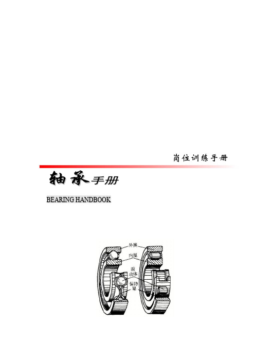
岗位训练手册轴承手册B E A R I N G H A N D B O O K目录第一章滚动轴承知识··············································································错误!未定义书签。
第一节滚动轴承分类和特性(GB/T-271-1997)······································错误!未定义书签。
一、滚动轴承构造类型分类····························································错误!未定义书签。
NSK轴承样本

Higher Load Rating
Basic dynamic load rating, N Basic dynamic load rating, N
600 000
EM M 500 000
400 000
300 000
200 000
100 000
0
210
220
310
320
Bearing number
1 200 000
8 500
10 000
90
23
1.5
1.5
52
83 000
81 500
6 700
8 500
85
19
1.1
1.1
54.5
63 000
66 500
7 500
9 000
100
25
1.5
1.5
58.5
97 500
98 500
6 300
7 500
90
20
1.1
1.1
59.5
69 000
76 500
7 100
8 500
NU313EM NJ NUP
76
NU214EM NJ NUP
78
NU314EM NJ NUP
81
NU215EM NJ NUP
83
NU315EM NJ NUP
Tests confirm that the stress levels of NSK’s EM series cages are 50% lower than that of major competitor’s M series.
Cage strength test results
申龙电梯天津佳利IP21扶梯驱动主机轴承更换指导
天津佳利IP21扶梯驱动主机轴承更换指导Tiianjin Jiali Escalator Machine Bearing Replacement Guidance (IP21) 说明:该指导仅针对于天津佳利电梯电机有限公司生产的IP21商务性扶梯驱动主机。
NOTE: This guidance is only for the business escalator machine (IP21) which made by Tianjin Jiali Escalator Motor Co., Ltd.一.拆除前需准备的工具和工装如下:一. The tools and tooling should be prepared before removed which is as following:1.轴承拆卸和安装工装,如下面照片所示,其中拆卸工装由我公司提供,工装图纸见附页。
The tooling of the bearing removal and installation is as following, where the tooling provided by ourcompany, and the drawing of the installation tooling see the Annex page.拆卸工装 安装工装2.规格为5t的液压拉马或同等规格的普通拉马,液压拉马照片如下:Hydraulic puller (specification 5t) or equivalent common puller, The photo of the Hydraulic puller is asfollowing:3.规格为12,13和19的扳手,参考下面照片:Spanner (specification 12, 13, 19) The photo is as following:4.规格为4和8的内六角扳手,参考下面照片:Hexagon ring spanner (specification 4, 8) The photo is as following:5.规格为10的活动扳手,参考下面照片:Monkey wrench (specification10) The photo is as following:6.木槌或胶皮槌,参考下面照片:Mallet or glue mallet, The photo is as following:7.简易加热装置,如电炉等,参考下面照片:Simple heating devices, such as the electric cooker, The photo is as following:扶梯驱动主机 Escalator machine三.扶梯主机轴承更换过程 The replacement process of the escalator bearing1.拆除主机飞轮1. Removed the escalator flywheel.第一步:用规格为8的内六角扳手将飞轮上的压板拆除,如下照片所示:Step 1, Removed the plate on the flywheel by the Hexagon ring spanner (specification 8) The photo is as following:第二步:用拉马将飞轮拆除,如下照片所示:Step 2, Removed the flywheel by the puller. The photo is as following:第三步:将轴头键拆除,如下照片所示:Step 3, Removed the shaft key, The photo is as following:2.拆除主机开关支架:用规格13的扳手将开关支架拆除,如下照片所示:Removed the switch bracket by the spanner (specification 13) The photo is as following:3.拆除主机上扶梯电机的风窗 Removed the air window of the machine.第一步:用活动扳手将风窗上的螺栓拆除,如下照片所示:Step 1, Removed the bolt of the air window by the monkey spanner, The photo is as following:第二步:将风窗拆除,如下照片所示:Step 2, Removed the air window. The photo is as following:4.将扶梯电机从齿轮箱上拆下 Removed the gearbox of the motor.第一步:用规格19的扳手将齿轮箱与扶梯电机之间的4颗螺栓拆下,如下照片所示:Step 1, Removed the 4 bolts between the gearbox and the motor by the spanner (specification 19)The photo is as following:第二步:用安全可靠的吊钩或软绳与扶梯电机两侧可靠连接,如下照片所示:Step 2, Connect the both side of the motor by the firm suspend hook or soft rope.The photo is as following:第三步:使用竖直向上的拉力将扶梯电机与齿轮箱分离,如下照片所示:Step 3, Separated the motor and gearbox by the perpendicular‐up pull.The photo is as following:5.扶梯电机联轴器的拆除:Removed the couple of the motor.第一步:将扶梯电机水平放置,用规格为4的内六角扳手将联轴器紧定螺钉拧松,如下照片所示: Step 1, Put the motor in the horizontal position, and loosen the screw by the Hexagon ring spanner (specification 4) The photo is as following:第二步:用拉马将联轴器拆除,如下照片所示:Step 2, Removed the couple by the puller. The photo is as following:第三步:将轴伸键用合适的工具拆除,如下照片所示:Step 3, Removed the shaft key by the appropriate tools. The photo is as following:6.扶梯电机凸缘端盖的拆除: Removed the flange cover of the motor:第一步:用规格13的扳手将凸缘端盖的8颗螺栓拆除,如下照片所示: Step1, Removed the 8 bolts of the flange cover by the spanner (specifications 13) The photo is as following:第二步:用木槌轻轻敲击凸缘端盖,将其拆下:Step 2, Knocked on the flange cover slightly by the mallet and then removed.注意:在拆下凸缘端盖后,请务必将轴承垫圈放回凸缘端盖的轴承室内,轴承更换完成并装回凸缘端盖时, 轴承垫圈必须按原样装回,如下照片所示:NOTE: After removed the flange cover, please put the gasket back the bearing chamber, when the replacement process finished, the bearing gasket should be installed as the original.轴承挡圈 End ring轴承挡圈在轴承室中的位置 The position of the end ring in the bearing house7.扶梯电机前轴承的更换:The replacement of the front bearing.第一步:用拉马将前轴承拆除,如下照片所示:Step 1, Removed the front bearing by the puller. The photo is as following:第二步:将相同品牌和型号的新轴承装在电机转子的轴承台上,如下照片所示:Step 1, Put the new bearing that the same brand and type on the bearing desk.The photo is as following:第三步:用木槌轻轻敲击轴承安装工装使轴承进入轴承台,直至无法进入为止,如下照片所示, Step 3, Knocked on the installation tooling of the bearing by the mallet slightly, and then put the bearing into the bearing desk until it can not entered. The photo is as following:注:如果现场有条件的话,可使用专用轴承加热器加热后放入。
轴承型号及其含义资料
轴承型号及其含义内径代号:一般情况下轴承内径用轴承内径代号(基本代号的后两位数)×5=内径(mm,例:轴承6204的内径是04×5=20mm。
常见特殊情况:㈠当轴承内径小于20mm轴承内径尺寸为(mm10121517对应内径代号为00010203㈡当轴承内径小于10mm,直接用基本代号的最后一位表示轴承内径尺寸;例:轴承608Z,用基本代号‘608’的最后一位8作内径尺寸,轴承608Z 的内径为8mm。
以此类推627的内径为7mm,634的内径为4mm。
㈢轴承的内径不是5的倍数或者大于等于500mm,内径代号用斜杠‘/’隔开。
另一种情况:有部分滚针轴承旧代号内径代号直接用‘/’隔开。
这几种情况‘/’后边的几位数值为轴承内径尺寸。
见下表示例:轴承型号619/1.562/2260/5003519/11207943/25内径尺寸(mm1.522500112025以上是几种轴承内径常见的表示方法,国际上有些公司的代号都不尽相同;要以实际情况为准。
具体要参考各种资料和各厂家样本。
尺寸系列代号:用于表达相同内径但外径和宽度不同的轴承,见图。
直径代号宽度代号外径系列代号:特轻(0,1,轻(2,中(3,重(4宽度系列代号:一般正常宽度为“0”,通常不标注。
但对圆锥滚子轴承(7类和调心滚子轴承(3类等类型不能省略“0”6010为轻薄系列,应用于轻载荷、高转速;6210是轻型系列,轻型负荷转速最合理,是应用面最广的类型;6310是中重型系列;6410是重系列,用于重载低速。
中型和中重型应用最广,如各类机械传动部件、中小型电动机、流水线传送带、摩托车等等各种机械设备几乎都有用到这两种类型。
类型代号:应记住常用的轴承代号:3,5,6,7,N五类,对应老代号为7,8,0,6,2类。
.公差等级代号见表:向心轴承和角接触球轴承分五级见下表(高→低)新等级代号P2P4P5P6P0旧等级代号B C D E G圆锥滚子轴承分四级见下表(高→低)新等级代号P4P5P6x P015mm 和17mm 的轴承,内径代号依次为00、01、02和03。
NSK轴承简介
补充:
1.轴承的内径 轴承型号的后两位数乘以5就是轴承的公制内径 此算法适用于轴承后两位数04(含04)以后的轴承型号,04之前的轴承内径都是固定的 00:内径10MM 01:内径12MM 02:内径15MM 03:内径17MM 轴承型号后两位21之后只有复数,没有单数 例:6023 1223 型号是不正确的
例如:3200* 系列带XJ 320 330系列是J
• *此类型轴承客户一般都会给出完整型号的 如果客户询价:7520 这个为国内旧型号 新型号为32220
可参考 中华轴承网/?mode_x=1 佰联轴承网/ 金蜘蛛轴承网/gb/dictionary.aspx
4.油脂:
NS7 油脂 耐温-40° + 130° ENS 油脂 耐温-40° +160°
5.6205ZZC3**ER
**表示轴承上没有C3的标识 ER:轴承的静音等级 R:比ER低一级的静音等级
6.包装方式:
5:商包 6:工包 7:桶装 S/Q:金色包装 X:新式包装 商包
7.产地:
LR:沈阳产 H:昆山 BH:合肥 LC:苏产(圆锥滚子轴承,现已很少生产) J:印尼 MA:马来西亚
2. 配对方式 SU:单个万能组合 DU:成对万能组合 DB:背对背组合 DF:面对面组合 DT:串联组合 DBD:三个一组 DBB:四个一组 BG:40°角 铜保单个万能组合 BWG:40°角 钢保单个万能组合
3.预压 L:轻预压 M:中预压 4.精度 P5 <P4<P4Y
*此类型轴承客户询价,需确认 角度 配对方式 精度 保持架都是尼龙保保持架 产地都是日本 型号后缀有带V1V的是带胶盖的
NSK轴承简介
• 1.深沟球轴承 • 2.角接触球轴承 • 3.调心滚子轴承 • 4.调心球轴承 • 5.单列圆柱滚子轴承 • 6.双列圆柱滚子轴承 • 7.圆锥滚子轴承 • 8.推力球轴承 • 9.外球面轴承 • 10.滚珠丝杠支撑用轴承 • 11.超高速角接触球轴承 • 12.高速推力角接触球轴承
NSK滚动轴承样本

15. 7 26 000 15 000 30 0005 000 28 000 6903 ZZ V V D D U
14. 4 22 000
26 000 16003
14. 4 22 000 13 000 26 000 6003 ZZ V V D D U 13. 2 17 000 12 000 20 000 6203 ZZ V V D D U 12. 4 15 000 11 000 18 000 6303 ZZ V V D D U
B4
开放型
结构·型式与特征
单列深沟球轴承 单列深沟球轴承,有如左图所示的结构。 防尘盖球轴承及密封圈球轴承,封入了适量的优质润滑脂。将密 封球轴承的特性做比较,则如表1所示。
带有止动环
结 构
表1 密封球轴承的特性
防尘盖型 (ZZ型)
非接触橡胶密封圈式 (VV型)
接触橡胶密封 (DDU型)
B8
γN a b γ0
Da D1
γa
γa
da
DX
CY
当 量 动 载 荷 P=XFr+ YFa
> >
f 0 Fa C 0r
e
Fa Fr
=e
X
Y
Fa Fr
>e
X
Y
0.172 0.19 1
0 0.56 2.30
0.345 0.22 1
0 0.56 1.99
γa
0.689 0.26 1
0 0.56 1.71
B6
尺寸精度·旋转精度
单列深沟球轴承 ...................... 表8.2 (A60~A63页)
满球轴承
....................... 表8.2 (A60~A63页)
NSK轴承样本

我们在力求便于用户选择各种 SPACEA 系列产品的同时,还增加了诸如产品尺寸、精度及润滑剂、 材料等相关内容,为用户奉献一册得心应手的综合性产品样本。
1. 不锈钢 SPACEATM 轴承 2. 超耐蚀防水型树脂轴承 3. 全陶瓷轴承 E SPACEATM 轴承产品规格、使用须知、技术参数 .................... P30 〜 P65 1. 不锈钢轴承 ......................................................................... P30 〜 P31 2. 自润滑(lubricated)轴承 .................................................. P32 〜 P33 3. 混合型轴承 ......................................................................... P34 〜 P35 4. 耐蚀镀膜轴承(镍膜)......................................................... P36 〜 P37 5. 超耐蚀、非磁性不锈钢 ESA 轴承........................................ P38 〜 P39 6. 全陶瓷轴承(氧化物类陶瓷).............................................. P40 〜 P41 7. 超耐蚀防水型树脂轴承 ....................................................... P42 〜 P43 8. 超耐蚀全陶瓷轴承(碳化物类陶瓷).................................... P44 〜 P45 9. 填充纯净润滑脂轴承(大气专用)....................................... P46 〜 P47 10. 填充纯净润滑脂轴承(大气~真空).................................... P48 〜 P49 11. 氟基固体润滑保持架轴承.................................................... P50 〜 P51 12. 纯净润滑剂 V-DFO 轴承...................................................... P52 〜 P53 13. YS 型固体润滑保持架轴承(MoS2 类)............................... P54 〜 P55 14. 填充耐高温润滑脂轴承(大气专用).................................... P56 〜 P57 15. YS 型隔垫式耐高温轴承 ..................................................... P58 〜 P59 16. SJ 型耐高温固体润滑轴承 .................................................. P60 〜 P61 17. 完全非磁性钛合金轴承 ....................................................... P62 〜 P63 18. 粉尘工况专用自润滑(Lubricated)轴承 ........................... P64 〜 P65 F SPACEATM 轴承使用举例 .......................................................... P66 〜 P71
INA FAG轴承样本中文版-圆锥滚子轴承
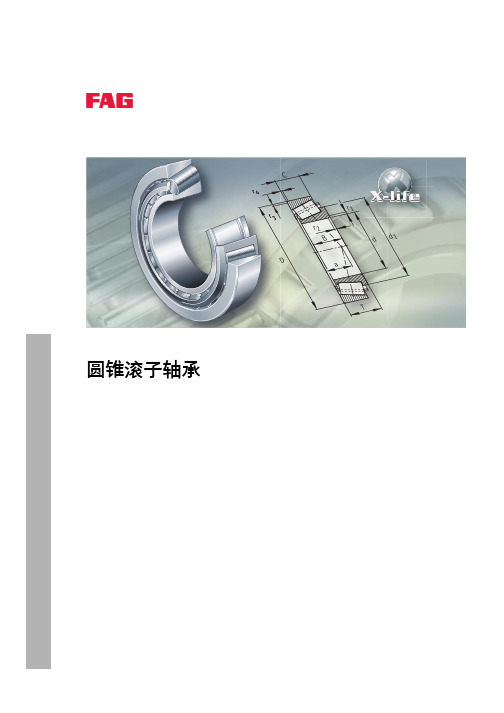
圆锥滚子轴承 JK0S 为单侧密封的即装即用单元,主要用于 O 型 布置配对安装。它们是不可分离轴承,且不需要再注脂。
无需设定轴承对的内部轴向游隙。是因为当用轴螺母或轴端盖 夹紧内圈时,内外圈之间存在非常小的突出量 ( 尺寸 u)。 为了获得正确的安装后轴向游隙,内圈和外圈需要采用紧配合。 整体式圆锥滚子轴承以 O 型布置配对使用时,外圈会形成一个 适宜的环形槽以供卡环 BR 定位。卡环必须单独订购。
F轴a 承轴向动载荷
N
F轴r 承径向动载荷
N
e, Y
–
系数,见尺寸表。
对于动载荷下的 O 型或 X 型布置的轴承对,采用下面公式:
载荷比
轴承当量动载荷
Fa Ϲ e Fr
P = Fr + 1.12 · Y · Fa
Fa Ͼ e Fr
P = 0.67 · Fr + 1.68 · Y · Fa
212 009b
整体式圆锥滚子轴承 JK0S
单侧密封
00010A96
516 HR 1
Schaeffler Group Industrial
圆锥滚子轴承
特性
径向和轴向承载能力
接触角
圆锥滚子轴承由具有锥形滚道的实体内、外圈和采用窗式保持架 的圆锥滚子组件组成。 轴承形式有: ■ 标准设计 ■ 配对的开式变型设计 ■ 单侧密封的整体式设计, JK0S。 开式轴承是可分离轴承。因此,带有滚子与保持架组件的内圈和 外圈能够分开安装。 提供公制和英制轴承。型号中带有字母 K 的轴承为英制轴承。 在新设计中,请优先选用公制的圆锥滚子轴承 。
INA FAG轴承样本中文版-圆柱滚子轴承
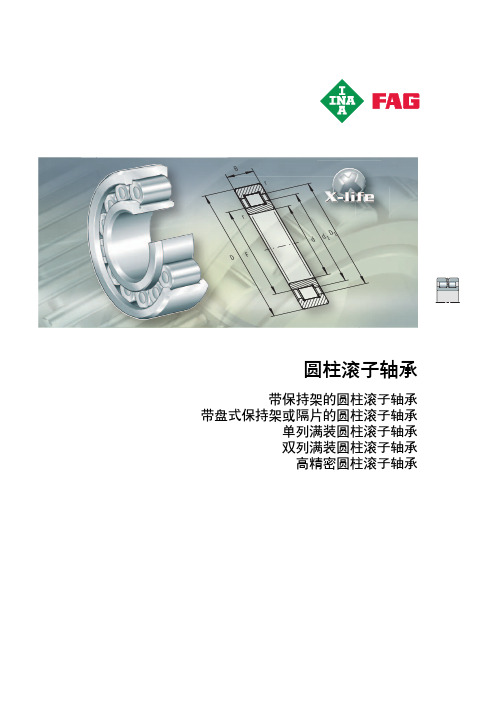
d BrrD d11DF圆柱滚子轴承带保持架的圆柱滚子轴承带盘式保持架或隔片的圆柱滚子轴承单列满装圆柱滚子轴承双列满装圆柱滚子轴承高精密圆柱滚子轴承圆柱滚子轴承带保持架的圆柱滚子轴承 (394)带保持架的单列圆柱滚子轴承具有很高的径向承载能力,与满装滚子轴承相比,适用于较高的转速。
滚动体由内圈或外圈的两个挡边引导,通过保持架和这个套圈组成一个单元。
这种轴承的一个套圈可拆下,因此内外圈可分别安装。
这类轴承可作为浮动、半定位及定位轴承。
带盘式保持架或隔片的圆柱滚子轴承 (446)这类轴承的黄铜盘式保持架或塑料隔片防止了滚动体间的相互接触。
此类轴承是介于满装轴承与带保持架轴承之间的一种设计。
滚动体由外圈的刚性挡边引导。
内圈可拆分,因此内外圈可以分开安装。
此类轴承专门用作半定位轴承。
单列满装圆柱滚子轴承 (460)此类轴承带有满装圆柱滚子组。
滚动体由套圈挡边引导。
由于具有尽可能多的滚子,满装圆柱滚子轴承具有极高的承载能力和高刚性。
限于运动学条件,此类轴承没有带保持架的圆柱滚子轴承那样高的极限转速。
此类轴承专门用作半定位轴承。
双列满装圆柱滚子轴承 (478)滚动体由套圈挡边引导。
轴承具有极高的承载能力和高刚性。
限于运动学条件,该类轴承没有带保持架的圆柱滚子轴承那样高的极限转速。
索轮轴承(轴承外圈带有止动槽)通过止动环可以很方便地进行轴向定位。
双列满装圆柱滚子轴承可用作浮动、半定位及定位轴承。
高精密圆柱滚子轴承 (500)这类双列高精密圆柱滚子轴承(浮动轴承)主要应用于机床,精度等级为SP。
可为主轴提供径向支撑。
此类轴承外圈可拆分,因而便于安装与拆卸。
内圈带有圆锥内孔,用于轴承内部游隙的优化设置。
392HR 1Schaeffler Group IndustrialSchaeffler Group Industrial HR 1393FE Br r1d D带保持架的圆柱滚子轴承页带保持架的圆柱滚子轴承产品概览带保持架的圆柱滚子轴承 (396)特性 (397)浮动轴承 (397)半定位轴承 (397)定位轴承 (398)密封 (398)润滑 (398)工作温度 (398)保持架 (398)后缀 (399)设计与安全指南容许的倾斜角度 (400)轴向承载能力 (400)最小径向载荷 (401)轴承当量动载荷 (402)轴承当量静载荷 (402)轴承布置设计 (402)精度内部径向游隙 (403)尺寸表带保持架的圆柱滚子轴承,浮动轴承 (404)带保持架的圆柱滚子轴承,半定位轴承与定位轴承..............420Schaeffler Group Industrial HR 1395396HR 1Schaeffler Group Industrial 产品概览带保持架的圆柱滚子轴承浮动轴承NU10、NU19、NU2..-E 、NU4、NU3..-E 、NU22..-E 、NU23..-E N2..-E 、N3..-E113 437a 113 439a半定位轴承NJ2..-E 、NJ3..-E 、NJ4、NJ22..-E 、NJ23..-E113 430a 定位轴承带平挡圈NUP2..-E 、NUP3..-E 、NUP22..-E 、NUP23..-E113 438a 带L 型斜挡圈NJ2..-E+HJ 、NJ3..-E +HJ 、NJ4+HJ 、NJ22..-E +HJ 、NJ23..-E +HJ00014089Schaeffler Group Industrial HR 1397特性带保持架的单列圆柱滚子轴承由内圈、外圈、圆柱滚子及保持架组件构成。
NSK轴承样本
1High Precision Angular Contact Ball Bearings (Standard Series) P48-60FeaturesNumbering System Bearing TablesMiniature Series, BSA Series for Ball Screw Support79 Series 70 Series 72 Series Ultra High-Speed Angular Contact Ball Bearings (ROBUST Series) P62-79FeaturesNumbering System Bearing TablesBNR19, BER19 Series BNR10, BER10 SeriesBNR19XE/10XE, BER19XE/10XE Series (Spinshot™I I )BNR29, BER29 Series (Wide Series)BNR20, BER20 Series (Wide Series)Ultra High Precision Angular Contact Ball Bearings (ROBUST Series —BGR) P80-84FeaturesNumbering System Bearing TablesBGR19 Series BGR10 Series BGR02 SeriesAngular Contact Ball BearingsAngular Contact Ball BearingsA n g u l a r C o n t a c tB a l l B e a r i n g sPart4High Precision Angular Contact Ball Bearings (Standard Series)FeaturesSingle-row angular contact ball bearings have a line connectingthe contact points drawn in the radial direction, which is calledthe contact angle. The contact angle makes this bearingsuitable for accommodating radial loads, single direction axialloads, and a combination of both. Furthermore, since an axialcomponent is generated when a radial load is applied, thesebearings are generally used in pairs, triplex sets, quadruplexsets, or multiplex sets.Contact AngleWhen a load is applied to an angular contact ball bearing,elastic deformation and the amount of stress at the contactpoint changes as a result of the varying load conditions of theballs, inner ring, and outer ring according to the contact angleof the bearing.Figure 1.2 illustrates loads acting on two rolling elements for a30˚ contact angle, and a 15˚ contact angle. The relationbetween an axial load being applied to the bearing and resultingload acting on the rolling element can be formulated as:F a/(Number of balls ×sinα).Therefore, the larger the contact angle, the smaller the loadacting on the rolling element. Load at the contact point, and itsconsequential deformation, is reduced thus resulting in longerlife. When a radial load is applied, the smaller the contactangle, the smaller the load acting on the rolling element, thusresulting in reduced load at the contact point.(See Pages 42 and 43 for contact angle specifics.)Dimension Series7Bearing type7: single-row angular contact ball bearing42-43, 480Dimension9: 19 series, 0: 10 series, 2: 02 series42-43, 48C Contact angle C: 15˚, A5: 25˚, A: 30˚42-43, 48Material No symbol: bearing steel (SUJ2) SN24: ceramic ball (Si3N4) (1)14-1713Bore numberLess than 03, Bearing bore 00: 10 mm, 01: 12 mm 02: 15 mm, 03: 17 mm50-60Over 04, Bearing bore Bore number × 5 (mm)TYN Cage TYN: ball guided polyamide resin cage; limiting speed d m n= 1 400 000; operational temperature limit = 120˚C18-19TR: outer ring guided phenolic resin cage; operational temperature limit = 120˚CSeal No symbol: open type V1V: non-contact rubber seal (2)32L Preload EL: extra light preload, L: light preload, M: medium preload, H: heavy preload42-43CP: special preload, CA: special axial clearance152-160DB ArrangementSU: universal arrangement (single row) DU: universal arrangement (double row)42-43DB: Back-to-back arrangement DF: Face-to-face arrangement DT: tandem arrangementDBD, DFD, DTD, DUD: triplex set arrangement •DBB, DFF, DBT, DFT, DTT, QU: quadruplex set arrangement148-151P4AccuracyP2: ISO Class 2, P4: ISO Class 4, P5: ISO Class 5151P3: special class (dimensional accuracy: ISO Class 4; rotating accuracy: ISO Class 2)176-179P4Y: special class (Bore diameter and outside diameter are exclusive to NSK. All others are ISO Class 4.)Reference pages(1)Angular contact ceramic ball bearing correspondence numbers 79, 70: Bore diameter= φ 10-100 mm.(2)Sealed angular contact ball bearings are standardized for SU arrangement and ISO Class 3.Sealed angular contact ball bearing correspondence numbers 79, 70: Bore diameter= φ 30-100 mm.(1)For permissible axial load, please refer to Page 147.(2)For application of limiting speeds, please refer to Page 170. When a ceramic ball is used, limiting speed value will be 1.25 times the value of steel ball.Note :Bearing numbers with a “C” suffix: nominal contact angle 15˚Bearing numbers with an “A5” suffix: nominal contact angle 25˚(1)For permissible axial load, please refer to Page 147.(2)For application of limiting speeds, please refer to Page 170. When a ceramic ball is used, limiting speed value will be 1.25 times the value of steel ball.Note :Bearing type BSA: nominal contact angle 30˚High Precision Angular Contact Ball Bearings (Standard Series)79 SeriesBore Diameter 60-280 mm(1)For permissible axial load, please refer to Page 147.(2)For application of limiting speeds, please refer to Page 170.Note :Bearing numbers with a “C” suffix: nominal contact angle 15˚Bearing numbers with an “A5” suffix: nominal contact angle 25˚For additional information:Page No.(1)For permissible axial load, please refer to Page 147.(2)For application of limiting speeds, please refer to Page 170.When a ceramic ball is used, limiting speed value will be 1.25 times the value of steel ball.Note :Bearing numbers with a “C” suffix: nominal contact angle 15˚Bearing numbers with an “A5” suffix: nominal contact angle 25˚70 SeriesBore Diameter 10-75 mm(1)For permissible axial load, please refer to Page 147.(2)For application of limiting speeds, please refer to Page 170.When a ceramic ball is used, limiting speed value will be 1.25 times the value of steel ball.Note :Bearing numbers with a “C” suffix: nominal contact angle 15˚Bearing numbers with an “A5” suffix: nominal contact angle 25˚Bearing numbers with an “A” suffix: nominal contact angle 30˚(1)For permissible axial load, please refer to Page 147.(2)For application of limiting speeds, please refer to Page 170.When a ceramic ball is used, limiting speed value will be 1.25 times the value of steel ball.Note :Bearing numbers with a “C” suffix: nominal contact angle 15˚Bearing numbers with an “A5” suffix: nominal contact angle 25˚Bearing numbers with an “A” suffix: nominal contact angle 30˚For additional information:Page No.70 SeriesBore Diameter 80-200 mm(1)For permissible axial load, please refer to Page 147.(2)For application of limiting speeds, please refer to Page 170.When a ceramic ball is used, limiting speed value will be 1.25 times the value of steel ball.Note :Bearing numbers with a “C” suffix: nominal contact angle 15˚Bearing numbers with an “A5” suffix: nominal contact angle 25˚Bearing numbers with an “A” suffix: nominal contact angle 30˚(1)For permissible axial load, please refer to Page 14.(2)For application of limiting speeds, please refer to Page 170.Note :Bearing numbers with a “C” suffix: nominal contact angle 15˚Bearing numbers with an “A5” suffix: nominal contact angle 25˚Bearing numbers with an “A” suffix: nominal contact angle 30˚For additional information:Page No.72 SeriesBore Diameter 10-105 mm(1)For permissible axial load, please refer to Page 147.(2)For application of limiting speeds, please refer to Page 170.Note :Bearing numbers with a “C” suffix: nominal contact angle 15˚Bearing numbers with an “A5” suffix: nominal contact angle 25˚Bearing numbers with an “A” suffix: nominal contact angle 30˚(1)For permissible axial load, please refer to Page 147.(2)For application of limiting speeds, please refer to Page 170.Note :Bearing numbers with a “C” suffix: nominal contact angle 15˚Bearing numbers with an “A5” suffix: nominal contact angle 25˚Bearing numbers with an “A” suffix: nominal contact angle 30˚For additional information:Page No.72 SeriesBore Diameter 110-150 mm(1)For permissible axial load, please refer to Page 147.(2)For application of limiting speeds, please refer to Page 170.Note :Bearing numbers with a “C” suffix: nominal contact angle 15˚Bearing numbers with an “A5” suffix: nominal contact angle 25˚Bearing numbers with an “A” suffix: nominal contact angle 30˚Robust design achieved with NSK’s proprietary analytical technology.Optimum design achieved by computer simulation of temperature rise resulting from ball skid.New SHX steel material provides superior heat and wear resistance.Enhanced service life measures include raising the seizure limit under low lubrication and high-speed operating conditions.Dimension SeriesOptimum Design High AccuracyLong LifeRolling element material can be tailored to match the application.Ceramic balls are used for ROBUST series angular contact ball bearings.Highly accurate P2 series is available.NSK’s experience and know-how ensure bearing specifications with a high degree of accuracy.High SpeedCage engineered for high-speed operations.Benefits of the lightweight, high strength engineered resin cage include heat resistance and high rigidity, making this cage indispensable for high-speed applications.Low NoiseQuieter running high-speed spindle featuring Spinshot TM I I lubrication system.Eliminates noise caused by compressed air of the oil-air lubrication system.Ultra High-Speed Angular Contact Ball Bearings (ROBUST Series)FeaturesReference pages80Nominal bearing bore Bore diameter (mm)64-79BNR Bearing type BNR: 18˚ contact angle, BER: 25˚ contact angle42-43, 4810Dimension10: 10 series, 19: 19 series, 20: 20 series, 29: 29 series (1)42-43, 62P2: ISO Class 2, P4: ISO Class 4, P5: ISO Class 5151P4Accuracy P3: special class (dimensional accuracy: ISO Class 4; rotating accuracy: ISO Class 2)176-179P4Y: special class (Bore diameter and outside diameter are exclusive to NSK. All others are ISO Class 4.)ELPreloadEL: extra light preload, L: light preload, M: medium preload, H: heavy preload CP: special preload, CA: special axial clearance TYNCageTYN: ball guided polyamide resin cage; limiting speed d m n = 1 400 000; operational temperature limit = 120˚C 18-19T: phenolic resin cage with outer ring guide; operational temperature limit = 120˚C Seal No symbol: open type V1V: non-contact rubber seal (2)32DBBArrangement SU: universal arrangement (single row) DU: universal arrangement (double row)42-43DB: Back-to-back arrangement DF: Face-to-face arrangement DT: tandem arrangement 148-151DBD, DFD, DTD, DUD: triplex set arrangement DBB, DFF, DBT, DFT, DTT, QU: quadruplex set arrangement(1)Series 20 and 29 are exclusively for sealed angular contact ball bearings.(2)Sealed angular contact ball bearings are standardized for SU arrangement and ISO Class 3 standards.Sealed angular contact ball bearings correspondence numbers BNR19, BNR29, BER19, BER29, BNR10, BNR20, BER10 and BER20: Bore diameter=φ30–100 mm42-43152-155161-164BNR19 Series BER19 SeriesBore Diameter 25-80 mm(1)For permissible axial load, please refer to Page 147.(2)For application of limiting speeds, please refer to Page 170.Note :Bearing type BNR: nominal contact angle 18˚(1)For permissible axial load, please refer to Page 147.(2)For application of limiting speeds, please refer to Page 170.For additional information:Page No.BNR19 Series BER19 SeriesBore Diameter 85-150 mm(1)For permissible axial load, please refer to Page 147.(2)For application of limiting speeds, please refer to Page 170.Note :Bearing type BNR: nominal contact angle 18˚Bearing type BER: nominal contact angle 25˚(1)For permissible axial load, please refer to Page 147.(2)For application of limiting speeds, please refer to Page 170.Note :Bearing type BNR: nominal contact angle 18˚Bearing type BER: nominal contact angle 25˚For additional information:Page No.BNR10 SeriesFor additional information:Page No. BER10 SeriesBore Diameter 30-80 mm(1)For permissible axial load, please refer to Page 147.(2)For application of limiting speeds, please refer to Page 170.Note:Bearing type BNR: nominal contact angle 18˚Bearing type BER: nominal contact angle 25˚(1)For permissible axial load, please refer to Page 147.(2)For application of limiting speeds, please refer to Page 170.BNR10 Series BER10 SeriesBore Diameter 85-150 mm(1)For permissible axial load, please refer to Page 147.(2)For application of limiting speeds, please refer to Page 170.Note :Bearing type BNR: nominal contact angle 18˚Bearing type BER: nominal contact angle 25˚(1)For permissible axial load, please refer to Page 147.(2)For application of limiting speeds, please refer to Page 170.Note :Bearing type BNR: nominal contact angle 18˚Bearing type BER: nominal contact angle 25˚For additional information:Page No.BNR19XE SeriesBER19XE SeriesBore Diameter 40-110 mm(1)For permissible axial load, please refer to Page 147.(2)For application of limiting speeds, please refer to Page 170.Note:Bearing type BNR: nominal contact angle 18˚Bearing type BER: nominal contact angle 25˚(1)For permissible axial load, please refer to Page 147.(2)For application of limiting speeds, please refer to Page 170.Note:Bearing type BNR: nominal contact angle 18˚Bearing type BER: nominal contact angle 25˚Series For additional information:Page No.BNR29 SeriesBER29 SeriesBore Diameter 30-80 mm(1)For permissible axial load, please refer to Page 147.(2)For application of limiting speeds, please refer to Page 170.Note :Bearing type BNR: nominal contact angle 18˚Bearing type BER: nominal contact angle 25˚(1)For permissible axial load, please refer to Page 147.(2)For application of limiting speeds, please refer to Page 170.Note :Bearing type BNR: nominal contact angle 18˚Bearing type BER: nominal contact angle 25˚For additional information:Page No.Ultra High-Speed Sealed Angular Contact Ball Bearings (Wide Series)BNR29 Series BER29 Series Bore Diameter 85-100 mm(1)For permissible axial load, please refer to Page 147.(2)For application of limiting speeds, please refer to Page 170.Note :Bearing type BNR: nominal contact angle 18˚Bearing type BER: nominal contact angle 25˚(1)For permissible axial load, please refer to Page 147.(2)For application of limiting speeds, please refer to Page 170.Note :Bearing type BNR: nominal contact angle 18˚Bearing type BER: nominal contact angle 25˚BNR20 Series BER20 SeriesBore Diameter 55-100 mm(1)For permissible axial load, please refer to Page 147.(2)For application of limiting speeds, please refer to Page 170. Note:Bearing type BNR: nominal contact angle 18˚Bearing type BER: nominal contact angle 25˚(1)For permissible axial load, please refer to Page 147.(2)For application of limiting speeds, please refer to Page 170.Note:Bearing type BNR: nominal contact angle 18˚Bearing type BER: nominal contact angle 25˚For additional information:Page No.An outer ring guided cage is used to improve lubrication performance.The counter-bore inner ring improves oil-mist flow to ensure a stable oil supply.Special heat resistant SHX steel and ceramic balls significantly improve service life (X-type bearings).Dimension SeriesOptimum DesignEasy MountingLong LifeNon-separable inner ring design greatly simplifies mounting and dismounting procedures.Interchangeable assembly for any desired arrangement to meet customer needs.High AccuracyBGR Series are standardized for ISO Class 2 (ABMA ABEC 9).Ultra High Precision Angular Contact Ball Bearings (ROBUST Series —BGR)Features8Nominal bearing bore Bore diameter (mm)82-84BGR Bearing type BGR: 15˚ contact angle 42-43, 4810Dimension 10: 10 series, 19: 19 series, 02: 02 series 42-43, 80DU Arrangement SU: universal arrangement (single row) DU: universal arrangement (double row)T Cage T: phenolic resin cage with outer ring guide; operational temperature limit = 120˚C 18-19ELPreload EL: extra light preload42-43148-15142-43152-155, 165Reference pagesP2AccuracyP2: ISO Class 2, P4: ISO Class 4176-179P3: special class (dimensional accuracy: ISO Class 4; rotating accuracy: ISO Class 2)Ultra High Precision Angular Contact Ball Bearings(ROBUST Series—BGR)BGR19 SeriesBore Diameter 10-25 mm(1)For permissible axial load, please refer to Page 147.(2)For application of limiting speeds, please refer to Page 170.Note:Bearing type BGR: nominal contact angle 15˚(1)For permissible axial load, please refer to Page 147.(2)For application of limiting speeds, please refer to Page 170.Note:Bearing type BGR: nominal contact angle 15˚For additional information:Page No.Part 1Part 2Part3Part 4Part 5Part 6Part 7Part 81.ANGULAR CONTACT BALL BEARINGS Ultra High Precision Angular Contact Ball Bearings (ROBUST Series —BGR)BGR02 SeriesBore Diameter 10-25 mm (1)For permissible axial load, please refer to Page 147.(2)For application of limiting speeds, please refer to Page 170.Note :Bearing type BGR: nominal contact angle 15˚。
常用圆锥滚子轴承

80
81.5
96.5
4500
5600
31308
40
90
35.3
33
27
2
0.23
50
80
115
148
4500
5600
32308
45
68
15
14
12
0.6
0.21
50
63
22.2
32.8
5300
6700
32909X2
45
68
15
15
12
0.6
0.21
50
63
32
48.5
5300
6700
32909
内径
34.5
56.5
4000
5000
32912X2
60
85
17
17
14
1
0.22
66
79
46
73
4000
5000
32912
60
95
23
22
19
1.5
0.29
69
86
64.8
98
3800
4800
32012X2
60
95
23
23
17.5
1.5
0.29
69
86
81.8
122
3800
4800
32012
60
95
27
17
14
1
0.21
61
74
41.5
66.8
4800
6000
32911
55
叉车轴承

检测设备
显微硬度检测仪
18
轴承套拳沟道淬硬层
检测设备
显微组织检测仪 19
感应淬火区金相500倍
感应淬火与调质过渡区100倍
配套客户
序号
客户单位
1
合力叉车股份有限公司
2
杭州叉车股份有限公司
3
江淮重工股份有限公司
4
宁波如意叉车股份公司
5
上海龙工股份有限公司
代叉车有限公司
产品表面采用先进磷化特殊处理,使产品表面形成一层致密、均匀,附着 力好,耐蚀力强的钝化磷化膜,从而增强了轴承与门架间的结合力,提高轴承 表面耐蚀性、耐磨性与润滑性能。
8
叉车门架链轮轴承的工作原理
9
叉车门架链轮轴承为 抬高货物的主要受力轴 承,传动链条与轴承外 圈链槽配合,轴承内圈 与门架固定连接,要求 轴承有足够的承载能力 和小的摆动量,轴承能 够平稳、灵活运转。
10
叉车侧链轮轴承
各种结构的叉车侧链轮轴承 包括双列球式、嵌套轴承式、 滚子式、滚针式等。
11
轴承原材料
叉车滚轮轴承内、外圈采用优质真空精炼轴承钢 C&U3或中碳钢,采用定炉质量监控,对非金属夹杂物 的控制要求相当严格,氧含量小于10PPM,毛坯成型采 用哈特贝尔高速镦锻后一次冷辗扩加工工艺,使轴承内 部组织致密、晶粒细小,并具有理想的金属纤维流线分 布,提高了轴承滚道表面的抗疲劳性能。
产品采用现行行业先进的极限载荷设计方案,比一般 轴承额定载荷增加5%;采用优质轴承钢材C&U3,高速 锻工艺,所以轴承实际承载能力通常比其额定载荷大5% 左右,而实际寿命通常为其额定寿命的5~8倍。
双硬度工艺设计:先整体调质处理,使轴承套圈具有一 定的韧性和足够的强度,具有优良的综合机械性能,其调 质硬度30~ 42HRC,调质后再对滚道进行感应淬火处理, 使滚道硬度达到58~ 62HRC,滚道淬硬层3mm以上。然 后去应力回火。保证了轴承滚道与钢球之间的接触疲劳强 度,进而保证了轴承的寿命。由于轴承外表面硬度相对较 低,可以有效降低叉车门架的磨损,提高门架的寿命。
赛龙轴承工程手册
公制转换表长度1m=39。
37″1mm=0。
0393″力1N=0.2248磅1kg=2。
205磅压力1kg/cm²=14.223磅/英寸²1Mpa=145磅/英寸²符号和单位英制单位Ct=超过生产车间环境温度时的额外径向间隙英寸MMCs=吸水时的额外径向间隙d=轴径英寸MMEo=弹性模量1BS/SQN MPAID=轴承内径英寸MML=轴承长度英寸MMN=轴转速RPM RPM O。
D。
=轴承外径INCHES MM P=压力1BS/SQIN MPATa=生产车间环境温度(典型21℃(70℉))℉℃T0=运转温度℉℃W。
T=轴承壁厚INCHES MM α=热膨胀系数IN/IN/ ℉CM/CM/℃μ=摩擦系数IN/IN/ ℉CM/CM/℃V=线速度FT/MIN M/SEC γ=拍松比不同硬度比例的大约对照(译者:表略)韦氏硬度(VICKERS)硬度莱氏B(ROCK WELL B)(BARCOL)硬度(HARDNESS)柔度(SOFTNESS)冷冻装配温度干冰:–78℃(–109℉)液氮:–196℃(–320℉)可供其它THORDON技术信息A)THORDON海洋工程安装手册B)THORDON计算机尺寸计算程序如有需要请与当地THORDON分发商或THORDON轴承公司联系1目录1.THORDON定义2.摩擦学3.物理性能A 热效应B 水效应C 形状系数D 应力应变E 刚度F 压变形—蠕变—应力释放G 冲击/恢复 H 滞后量 I 化学防腐 J 选择过程 K 故障和失效原因4.设计指导A 应用分析B 轴承压力C 速度D P.V。
T图表EL/D比 J 选择过程 K 故障和失效原因5.THORDON轴承的应用设计A 应用设计B 过盈C 内径收缩D 运转间隙E 膨胀允差F 吸水允差G 分步计算H 实例计算 I 键轴承计算 J 计算机计算 K 高压轴承6.加工指导A 一般加工B 加工XL和SXLC 尺寸和表面粗糙度测量D 加工Composite定义:THORDON 弹性轴承材料是一种热凝树脂,是三维交叉结晶聚合物.THORDON是一种高强度和高韧性的人工合成聚合物,其性能比大多数其它轴承材料优越.这些材料包括:黄铜,巴氏合金,尼龙,TFE,酚醛树脂层压板,铁梨木,碳精,聚酰胺,高分子聚乙酰。
