RTD温度计工作原理
温度计的工作原理
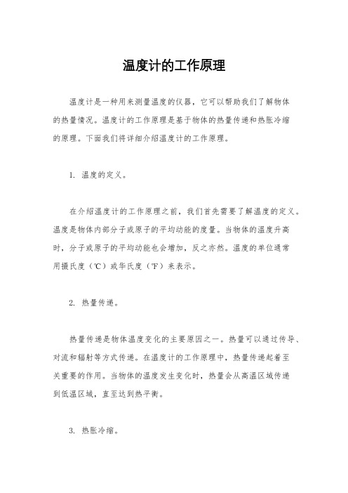
温度计的工作原理温度计是一种用来测量温度的仪器,它可以帮助我们了解物体的热量情况。
温度计的工作原理是基于物体的热量传递和热胀冷缩的原理。
下面我们将详细介绍温度计的工作原理。
1. 温度的定义。
在介绍温度计的工作原理之前,我们首先需要了解温度的定义。
温度是物体内部分子或原子的平均动能的度量。
当物体的温度升高时,分子或原子的平均动能也会增加,反之亦然。
温度的单位通常用摄氏度(℃)或华氏度(℉)来表示。
2. 热量传递。
热量传递是物体温度变化的主要原因之一。
热量可以通过传导、对流和辐射等方式传递。
在温度计的工作原理中,热量传递起着至关重要的作用。
当物体的温度发生变化时,热量会从高温区域传递到低温区域,直至达到热平衡。
3. 热胀冷缩。
热胀冷缩是指物体在温度变化时会产生体积的变化。
一般情况下,物体的体积会随着温度的升高而扩大,温度的降低而收缩。
这种现象是由于物体内部分子或原子的平均距离发生了变化。
温度计利用了热胀冷缩的原理来测量温度。
4. 温度计的工作原理。
温度计的工作原理主要基于热胀冷缩的原理。
常见的温度计包括水银温度计、酒精温度计、电子温度计等。
以水银温度计为例,它是由一根长而细的玻璃管内装有水银的温度计。
当温度升高时,水银会膨胀,从而上升到玻璃管内的刻度上。
反之,当温度降低时,水银会收缩,从而下降到玻璃管内的刻度上。
通过读取水银的高度,就可以得知物体的温度。
5. 温度计的精度。
温度计的精度是指温度计所测得的温度与实际温度之间的偏差。
温度计的精度受到多种因素的影响,如材料的热胀冷缩系数、制造工艺、环境温度等。
为了保证温度计的精度,通常需要进行校准和调整。
总结。
温度计是一种用来测量温度的重要仪器,它的工作原理基于物体的热量传递和热胀冷缩的原理。
通过测量物体的热胀冷缩情况,温度计可以准确地测量物体的温度。
在现代工业和生活中,温度计被广泛应用于各个领域,如气象、医疗、化工、食品加工等。
温度计的发展也推动了温度测量技术的不断进步,为人们的生活带来了便利。
rtd模块工作原理

RTD模块工作原理
1. 金属电阻特性
金属的电阻特性是温度系数(TCR)的概念。
TCR定义为温度每变化1摄氏度时,电阻值的相对变化。
这个系数通常用ppm/°C(每百万分之一摄氏度)来表示。
常见的金属材料如铜、镍、铁、铬等都具有正的温度系数,即随着温度的升高,电阻值也会相应地增加。
2. 温度测量原理
RTD(Resistance Temperature Detector)是电阻温度探测器的简称,它利用金属电阻随温度变化的特性来测量温度。
当温度变化时,RTD 的电阻值会相应地改变,通过测量电阻值,就可以推算出当前的温度。
3. 热敏电阻器
热敏电阻是一种特殊的电阻,其阻值随温度的变化而变化。
与金属RTD不同的是,热敏电阻通常具有负的温度系数,即随着温度的升高,电阻值会降低。
热敏电阻在温度测量中具有较高的灵敏度,通常用于需要精确测量温度变化的应用中。
4. 测量电路
为了测量RTD或热敏电阻的电阻值,需要使用一个测量电路。
最常用的测量电路是惠斯通电桥(Wheatstone bridge),它通过比较RTD或热敏电阻与一个已知电阻的电压差来测量电阻值。
测量电路输出的信号通常是一个电压或电流信号,它与RTD或热敏电阻的电阻值成比例关系。
5. 输出信号
RTD模块的输出信号通常是一个电压或电流信号,它表示当前温度下RTD或热敏电阻的电阻值。
通过将这个信号转换成数字信号并经过相应的处理,可以得到准确的温度读数。
输出信号的格式可以是4-20mA电流信号、0-5V电压信号或者0-10V电压信号等,具体取决于应用需求和设备配置。
rtd原理
rtd原理
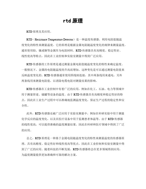
RTD原理及其应用。
RTD(Resistance Temperature Detector)是一种温度传感器,利用电阻值随温
度变化的特性来测量温度。
它的原理是根据金属电阻随温度变化的规律来测量温度,通常使用铂、镍或铜等金属作为电阻材料。
RTD传感器具有高精度、稳定性好、
线性度高等特点,因此在工业控制和实验室测量中得到广泛应用。
RTD传感器的工作原理是通过测量金属电阻值随温度变化的特性来确定温度。
一般情况下,金属的电阻随温度的升高而增加,这种变化是可以通过测量电阻值来反映温度变化的。
RTD传感器通常使用四线制连接,其中两条线用来通电,另外
两条线用来测量电阻值,以消除电缆电阻对测量结果的影响。
RTD传感器在工业控制中有着广泛的应用,例如在化工、石油、电力等领域中用于测量管道、储罐等设备的温度。
由于RTD传感器具有高精度和稳定性好的特点,因此在工业生产过程中可以准确地监测温度变化,保证生产过程的稳定性和安全性。
此外,RTD传感器还被广泛应用于实验室测量中,例如在科研实验中用于测量化学反应的温度变化,以及在医疗设备中用于监测患者体温等。
由于RTD传感器
的线性度高,可以提供准确的温度测量结果,因此在科研和医疗领域中得到了广泛的应用。
总之,RTD原理是一种基于金属电阻随温度变化的特性来测量温度的传感器原理,具有高精度、稳定性好和线性度高等优点,因此在工业控制和实验室测量中得到了广泛的应用。
随着科技的不断发展,RTD传感器将会在更多领域得到应用,
为温度测量提供更加准确和可靠的解决方案。
rtd原理

rtd原理
RTD原理。
RTD(Resistance Temperature Detector)是一种温度传感器,利用金属电阻的温度特性来测量温度。
RTD的工作原理基于金属电阻随温度变化而变化的特性,通常采用铂、镍或铜等材料制成的电阻体,具有较高的精度和稳定性,被广泛应用于工业自动化控制、航空航天、医疗设备等领域。
RTD的工作原理主要包括电阻温度特性、电阻温度曲线和测温电路。
首先,金属电阻的电阻值随温度的变化而变化,不同金属材料具有不同的温度特性,常用的铂电阻温度特性较为稳定,因此被广泛应用于RTD传感器中。
其次,金属电阻的温度特性可以通过电阻温度曲线来描述,即随着温度的升高,电阻值呈现出一定的变化规律,这种变化规律可以通过温度-电阻转换关系来表示。
最后,测温电路通过读取RTD传感器的电阻值,并根据预先建立的温度-电阻转换关系,计算出实际的温度数值。
在实际应用中,RTD传感器通常与测温仪表、温度变送器或控制系统相结合,用于实时监测和控制温度。
由于RTD具有较高的精度和稳定性,因此在工业领域中得到了广泛的应用。
例如,在化工生产过程中,需要对反应器的温度进行实时监测和控制,这时就可以使用RTD传感器来实现。
另外,在航空航天领域,RTD传感器也被广泛应用于飞机发动机的温度监测,确保发动机的安全运行。
总之,RTD传感器利用金属电阻的温度特性来测量温度,具有精度高、稳定性好的特点,被广泛应用于工业自动化控制、航空航天、医疗设备等领域。
通过深入了解RTD的工作原理,可以更好地应用和维护RTD传感器,确保其正常运行,为各行业的生产和工作提供可靠的温度监测和控制。
热辐射温度计
热辐射温度计
热辐射温度计是一种通过测量物体热辐射的仪器,用于确定物体的温度。
物体发出的热辐射是由其温度决定的,热辐射温度计利用这一原理进行测量。
热辐射温度计可以测量广泛的温度范围,从极低温度到极高温度都可以应用。
它可以测量非接触物体的温度,因此非常适用于需要远距离测量或无法接触到物体表面的情况。
热辐射温度计的工作原理是基于斯特藩-玻尔兹曼定律,该定律表明物体的热辐射能量与其温度的四次方成正比。
热辐射温度计通过测量物体的热辐射能量,然后计算出物体的温度。
常见的热辐射温度计有红外线热像仪和红外线测温枪。
红外线热像仪通过测量物体发出的红外线辐射图像来确定温度分布,可以用于大范围的温度测量。
红外线测温枪则通过测量物体表面的红外线辐射来确定温度,适用于小范围的测量。
热辐射温度计在工业生产、医疗、建筑等领域有广泛的应用。
它可以用于检测设备的热量、监控物体的温度变化、测量人体体温等。
RTD介绍

电阻温度检测器(RTD)技术分类:仪表与过程传感器作者:Dale Cigoy,Keithley Instruments 公司高级应用经理发表时间:2006-03-24在无论是采用2线、3线还是4线配置,RTD都证明是一种稳定而又精确的测温器件,但也最昂贵。
了解RTD 的优点与缺点,有助于您进行温度测量决策。
众多测量温度(或测温)方法中,电阻温度检测器(或电阻测温器,通常简称为RTD)是最精确的一种方法。
在RTD中,器件电阻与温度成正比。
尽管有些RTD使用镍或铜,但RTD最常用的电阻材料还是铂。
RTD拥有很宽的温度测量范围。
根据其构造,RTD可测量-270~850℃的温度范围。
RTD需要有外部激励(通常为一个电流源)才能适当地工作。
但电流也会在电阻元件中产生热,从而引起测量误差。
温度误差可用下式计算:△T = P x S其中T为温度,P为所产生的功率I2R,S的单位是℃/mW。
测量方法有多种用RTD测量温度的方法。
一种是让电流通过RTD并测量其上电压的2线方法。
其优点是仅需要使用两根导线,因而容易连接与实现。
缺点是引线电阻会参与温度测量,从而引入一些误差。
2线方法的一种改进是3线方法。
其中虽然也采用让电流通过电阻并测量其电压的方法,但使用第三根线可对引线电阻进行补偿。
这需要有一个第三线补偿测量单元,或需要测出第三根线上的温度值,并将其从总的温度测量值上减去。
图1:典型2 线电阻测温方法示意图。
图2:典型4 线电阻测量方案,有助于消除温度测量中的大部分噪声与不确定性。
第三种方法是4线法。
与其它两种方法一样,4线法中也同样采用让电流通过电阻并测量其电压的方法。
但是从引线的一端引入电流,而在另一端测量电压。
电压是在电阻元件(RTD)上、而不是和源电流在同一点上测量,这意味着将引线电阻完全排除在温度测量路径以外。
换句话说,引线电阻不是测量的一部分,因此不会产生误差。
例如,如果引线电阻约为100毫欧,而RTD为100欧姆,则引线电阻大约会产生0.1%的测量误差。
RTD信号概述
RTD信号及测量概览本文档属于《常规测量指南》的一部分。
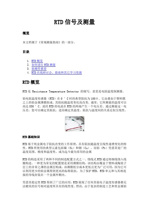
目录1.RTD概览2.如何进行RTD测量3.软硬件推荐4.RTD在线研讨会、指南和其它学习资源RTD概览RTD是 Resistance Temperature Detector 的缩写,意思是电阻温度探测器。
铂电阻温度传感器(RTD)在0 °C时的典型阻抗为100Ω。
它由叠加于塑料膜之上的铂金属薄膜组成。
其阻抗随温度变化而改变,通常,它所测量的温度可以高达850 °C。
流经RTD的电流在RTD的两端产生一个电压差。
通过测量这一电压差,您可以确定其阻抗,进而确定其温度。
阻抗与温度间的关系近似呈线性。
RTD基础知识RTD基于纯金属电子阻抗改变的工作原理,具有阻抗随温度呈线性递增变化的特性。
RTD所使用的典型元素包括镍(Ni)和铜(Cu),而铂(Pt)凭借其宽广的温度范围、精度和温度性,成为迄今最为常用的金属RTD的构造采用了两种不同的制造配置方式之一。
绕线式RTD通过将细线绕入线圈构造。
一种更为常见的配置便是采用薄膜结构,该结构由覆盖于塑料或陶瓷子层上的非常之薄的金属层构成。
该薄膜组分成本更低且更为广泛可用,因为它可以利用更少的铂金属得到更高的标称阻抗。
为了保护RTD,RTD单元和与其相连接的导线封装在一个金属外鞘内。
凭借其稳定性RTD得到了广泛的应用,RTD展现了任何其他电子温度传感器都无法媲美的信号相对温度所具有的线性度。
然而,由于复杂的制造工艺和贵金属铂的使用,它通常也比其替代品更为昂贵。
RTD还具有响应慢和敏感度低的特点,而且,由于需要电流激励,它容易产生自热现象。
RTD通常依据其在0 °C时的标称阻抗进行分类。
对于铂薄膜RTD,典型的标称阻抗包括100 Ω和1000 Ω。
其阻抗与温度间的关系近似呈线性,并遵循如下等式:当温度低于0 °C时,RT = R0 [ 1 + aT + bT2 + cT3 (T - 100) ](等式1)当温度高于0 °C时, RT = R0 [ 1 + aT + bT2 ]其中,RT 为温度为T时的阻抗,R为标称阻抗,a、b和c分别是RTD所使用的比例常数。
工作用热电阻

工作用热电阻
工作用热电阻(RTD,Resistance Temperature Detector)是一种测量温度的传感器。
它根据材料的温度变化来改变电阻值,从而实现温度测量。
RTD 的优点是精度高、稳定性好、可靠性强、响应速度快,因此在工业生产中得到广泛应用。
RTD 的工作原理是基于材料的电阻随温度变化而变化。
常用的 RTD 材料有铂、镍、铜、铁等金属。
其中,铂是最常用的材料,因为它具有较高的温度测量精度和较小的温度漂移。
当 RTD 与外部环境接触时,它会被加热或冷却,从而改变电阻值。
RTD 的电阻值可以通过电桥电路进行测量,电桥电路的输出信号与温度成正比。
RTD 的工作温度范围很广,一般可以测量从-200℃到+850℃的温度范围。
在测量温度时,需要考虑到RTD 的线性特性。
即,RTD 的电阻值随温度的变化应该是线性的。
如果存在非线性,那么就需要进行校准。
此外,还需要注意到 RTD 的电阻值在不同温度下变化的范围,以免造成测量误差。
RTD 在工业生产中被广泛应用,如食品加工、制药、化工、电力、航空航天等领域。
在这些领域中,温度的控制非常重要,因为它直接影响到生产的质量和效率。
RTD 可以帮助生产者及时掌握温度变化情况,保证生产过程的稳定性和可靠性,提高生产效率和产品质量。
RTD 是一种精度高、稳定性好、可靠性强、响应速度快的温度传感器。
它可以广泛应用于工业生产中,帮助生产者掌握温度变化情况,提高生产效率和产品质量。
在使用 RTD 进行温度测量时,需要注意到其线性特性和电阻值变化范围,以免造成测量误差。
温度和压力测量

1. 温度测量系统
温度传感器
热电阻 RTD
1.测量原理:电阻随着温度的变化而变化 2.热电阻的材料:有镍和铜,我们使用的铂,因为铂的温度范围宽,稳定 性和准确度高。一般测量范围在-50 ℃~260 ℃ 3.热电阻的类型:PT100 在0℃电阻在100Ω左右,100 ℃电阻在138.5 Ω左 右 4.热电阻的结构
1.温度测量系统
温度计传算感机器
WinDatSE的使用:
1. ID的配置 • 仪器 • 通讯方式和地址 • 通道 • 信号 • 标定数据
2.压力测量系统
压力传感器
信号转换器
连接线
计算机
1.压力传感器
1.485转232信号转 换器
1.232串口连接线
1.WindatSE软件
2.压力传感器连接 线
B转232连接线
2.压力测量系统
温压度力传感器
1.工作原理:
压力作用在膜片上时,电阻值发生变化并且产生一个与作用压力成正比 的线性输出信号。在惠斯通电桥上加上直流电源,就会产生一个直流电压信号的输出。 经过二次转换线路,实现模拟输出或数字输出。
2.压力测量系统
温压度力传感器
1.MODEL(传感器类型):DS 数字信号输出 2.RANGE(量程): 750PSIA or 750PSIG PSIA(绝压):以真空做为压力基点 PSIG(表压):以大气压为压力基点 3.EXC\SUPPLY(电源): 15~28VDC 4.OUTPUT(输出): 0~5V OR RS485 5.传感器地址:45 6. S/N(序列号): 1312598
1.温度测量系统
温数度据传采感集器
安捷伦34970a数据采集器
1.温度测量系统
热电偶温度传感器工作原理

热电偶温度传感器工作原理热电偶温度传感器(RTD)是一种常用的温度测量仪器,能够用来测量温度并将测量结果转换为电信号。
RTD主要由传感元件、放大器、运放电路和处理器等部分组成,工作原理是上述部件配合使用,将温度变化转换为电子信号,从而实现温度检测。
温度测量仪器传统上使用热电阻作为温度传感器,其原理是温度升高时,热电阻的电阻值也会升高,由此可以改变其电阻值来测量温度。
热电阻使用的是电阻的变化,而热电偶的改变则是在温度变化时偶电流的变化。
热电偶的工作原理是它由两种不同金属组成,当它们接触时,从金属的电阻变化现象中会产生一定的电流,随着温度的变化,这些电流也会有所变化。
热电偶的传感器由导热芯、绝缘芯和电缆等部分组成,它们之间有着严格的结构组合,可以使热电偶保持稳定性,使其能够持续测量温度。
当传感器接入电路时,由于其内部包含两个金属片,它们之间产生电流,并且由于热电偶片两端的温度是不同的,热电偶测量的电流如所料,随着温度的变化,测量的电流也会发生变化,这能够表示出温度的变化量。
电流变化被称为电阻温度系数(RTC),由于RTC的变化,热电偶可以准确地测量出温度变化量。
另外,热电偶还需要一定的放大电路,这种放大电路由放大器和运放电路组成,可以对从热电偶传感器中获得的信号进行放大,使其变化的更加明显,从而便于后续的处理。
最后,还需要一个处理器来处理温度信号,以便将温度数据以易于理解的方式显示出来,这样就可以检测到温度的变化情况,从而实现温度的控制。
综上所述,热电偶温度传感器的工作原理是,它通过两种不同金属之间的电流变化,并结合电路放大等技术,将温度变化转换为电子信号,便可以进行温度测量和控制。
热电偶具有稳定性高、可靠性好、响应时间短等优点,在工业自动化、航空航天等领域有着很广泛的应用。
厦门温度校验仪工作原理
厦门温度校验仪工作原理
厦门温度校验仪是一种用于测量和校准温度的仪器。
它的工作原理基于热传导和电阻温度测量原理。
以下是具体的工作原理:
1. 校验仪内部有一个温度传感器,通常是铂电阻温度传感器(RTD)或热电偶(Thermocouple)。
2. 当校验仪启动时,温度传感器感知环境的温度变化,并将其转换为电信号。
3. 校验仪中的电路将电信号进行放大和转换,将其转换为温度值。
4. 温度值通过显示屏或其他输出方式显示给用户。
5. 用户可以根据需要将校验仪与待测温度传感器连接起来。
待测温度传感器是需要被校验的温度传感器,可以是工业设备中的温度传感器、温度计等。
6. 校验仪将生成一个已知的参考温度,并将该温度传输给待测温度传感器。
7. 待测温度传感器将感知到的温度转换为电信号,并将其传输给校验仪。
8. 校验仪将接收到的电信号与已知的参考温度进行比较,并计算出待测温度传感器的误差。
9. 误差值通过显示屏或其他输出方式显示给用户,用户可以根据误差值进行校准或调整待测温度传感器的读数。
通过以上工作原理,厦门温度校验仪可以实现对待测温度传感器的准确度和稳定性的校准,并确保其能够准确地测量环境中的温度。
RTD 基础知识——电阻温度检测器简介-基础电子

RTD 基础知识——电阻温度检测器简介-基础电子电阻温度检测器或RTD 可能是简单的温度传感器类型。
这些设备的工作原理是金属的电阻随温度变化。
纯金属通常具有正的电阻温度系数,这意味着它们的电阻随温度升高而增加。
RTD 可在-200 °C 至+850 °C 的较大温度范围内工作,并提供高精度、出色的长期稳定性和可重复性。
在本文中,我们将讨论使用RTD 的权衡、其中使用的金属、两种类型的RTD,以及RTD 与热电偶的比较。
在深入探讨之前,让我们先看一个示例应用程序图,以更好地了解RTD 基础知识。
RTD 应用图示例RTD 是一种无源设备,不会自行产生输出信号。
图1 显示了一个简化的RTD 应用图。
图1.RTD 应用图示例。
图片由TI提供激励电流I1 通过传感器的温度相关电阻。
这会产生一个与激励电流和RTD 电阻成正比的电压信号。
RTD 两端的电压然后被放大并传送到ADC(模数转换器)以产生可用于计算RTD 温度的数字输出代码。
使用RTD 传感器的权衡——RTD 传感器的优点和缺点在深入研究之前,请务必注意RTD 信号调理的详细信息将在以后的文章中介绍。
对于本文,我想强调使用RTD 电路时的一些基本权衡。
首先,请注意,激励电流通常限制在 1 mA 左右,以限度地减少自热效应。
当激励电流流过RTD 时,它会产生I2R 或焦耳热。
自热效应可以将传感器温度升高到高于实际测量的周围环境温度的值。
减小励磁电流可以降低自热效应。
还值得一提的是,自热效应取决于RTD 浸入的介质。
例如,放置在静止空气中的RTD 的自热效应可能比浸入流动水中的RTD 更明显。
对于给定的可检测温度变化,RTD 电压的变化应该足够大以克服系统噪声以及不同系统参数的偏移和漂移。
由于自热效应限制了激励电流,我们需要使用电阻足够大的RTD,因此会为下游信号处理块产生较大的电压。
虽然需要较大的RTD 电阻以减少测量误差,但我们不能任意增加电阻,因为较大的RTD 电阻会导致响应时间变慢。
rtd原理
rtd原理
RTD或称为电阻温度计是一种被广泛应用于工业、实验室和医疗领域的温度测量设备。
它基于电阻温度特性来测量温度,其工作原理是当温度发生变化时,电阻率也会相应的改变。
RTD由一个细长且直径均匀的金属电阻丝组成,通常采用铂电阻丝,而其电阻值和温度之间的关系是线性的。
当温度增加时,电阻值也会随之增加,反之亦然。
这样,通过测量电阻值的变化,我们可以得到温度的值。
其中,温度与电阻值之间的关系可以由以下公式表示:
Rt=R0(1+αT)
其中,Rt是电阻值,R0是室温下的电阻值,α是电阻率随温度变化的系数,T为温度。
通常情况下,RTD被安装在测量物体的表面或内部,当被测物体发生温度变化时,RTD中的电阻值也会随之变化。
通过将其与一个稳定的电源相连,便可测量出电压和电流的变化,从而得到被测物体的温度。
RTD与其他温度测量设备相比,具有准确度高、线性度好、响应速度快等优点。
同时,它也有一些缺点,例如价格较高、对外部电源的依赖性较强等。
总的来说,RTD是一种可靠、稳定、准确的温度测量设备,其工作原理简单、易于实现,被广泛应用于各种温度测量场合中。
PT100(RTD)是什么?——2线,3线,4线原理用途全收纳
PT100(RTD)是什么?——2线,3线,4线原理用途全收纳RTDs - or Resistance Temperature Detectors- (电阻式温度探测器),是温度型传感器,包含一个电阻,这个阻值可以随温度的变化而变化。
在工业的进程中和实验室里已经使用了很多年,以精确,可靠和稳定的特性。
PT100 (RTD)PT100的2线制,3线制,4线制的区别和应用2线制2线制的是RTD里最简单的设计。
这是一个串联的设计,RTD两端分别有一个引出线,从这2个引出线去连接监控设备。
在计算温度变化的时候,其实就是计算电阻值的变化,但是这个电阻值包括了两个引出线是电阻和真实起作用的RTD器件,所以结果会有些偏差或者是错误。
2线制PT100因为导线上是有电阻的,我假设电阻为R1和R2,那监控设备实际得到的电阻Rt=R1+R2+Re测量的不准确的,所以可以用在精度要求不是太高的地方。
3线制PT100这个好多人不理解,也是我当时不太懂的地方。
3线制的RTD是工业生产和监控设备上用的最多的。
这个配置是在RTD的一端有两根引出线,在另一端只有一个引出线。
这样的设计,你必须把保证R1,R2,R3三根引用线是材料,长度和粗细是一致的,其实意思就是让三根线上的电阻值是一样的就可以。
3线制PT100其实是在监控设备里做了一个减法:Rt1 = R1+R2+ReRt2 = R2+R3因为三根线都是一样的:R1 = R2 = R3最后在监控设备里得到 Rt = Rt1-Rt2=Re这样测出来的电阻值就是Re变化的电阻值了,已经非常精确了,造价也不高,工业领域非常实用。
4线制PT1004线制平时用的不多,而且造价也贵,主要是用于实验室,要求精度极高的环境4线制PT1004线制的PT100相当于在R3和R4之间加了一个恒流源,保证电流是稳定的,因为电流是恒定的,R2和R1相当于开路,所以只要监测R2和R1两端电压U,根据U=IR,就可以算出Re的电阻值,从而得到非常精确的温度值。
热电阻测温原理
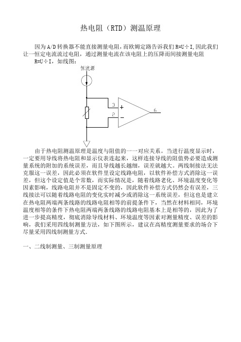
热电阻(RTD)测温原理因为A/D转换器不能直接测量电阻,而欧姆定路告诉我们R=U÷I,因此我们让一恒定电流流过电阻,通过测量电流在该电阻上的压降而间接测量电阻R=U÷I,如线图:由于热电阻测温原理是温度与阻值的一一对应关系。
当进行温度显示时,一定要用导线将热电阻和显示仪表连起来,这样连接导线的阻值势必要造成测量系统的附加的系统误差,而且导线越长越细,误差就越大。
两线制接法无法克服这一误差,因此必须在软件里设定线路电阻,以软件补偿方式消除这一误差,但这个设定值是个常数,而实际情况是,随着线路老化、环境温度变化等因素影响,线路电阻并不是固定不变的,因此软件补偿方式仍然会有误差,三线接法可以随着线路电阻的变化实时减少或消除这一系统误差,但这也是建立在热电阻两端两条线路的线路电阻相等的前提条件下,当然在材料相同,环境温度相等的条件下热电阻两端两条线路的线路电阻基本上是相等的,因此为了进一步提高精度,彻底消除导线材料、环境温度等因素对测量精度、误差的影响,我们采用四线制测量方法,如下图所示,建议在高精度测量要求的场合下尽量采用四线制测量方式.一、二线制测量、三制测量原理二线制方式下:运放输入差动电压:()22L t t L U R R I U R R I =÷+⨯-=⨯→⨯因此软件测得U ÷I 后需再减去预先设定的常数(线路电阻2R L )即可得到热电阻阻值R t 。
三线制测量方式下:由于两个恒流源电流相等并已知为I ,那么根据叠加定理,运放输入差动电压:[2) ()]((2)L t L L L L L U I R R R I I R R I I I R R U =⨯⨯+⨯-⨯⨯⨯=→+⨯=÷+当采用三线制测量方式时由于采用双恒流源,为了消除线路电阻带来的误差,要求两个恒流源的电流必须相等,还要要求热电阻两端的线路电阻必须相等,实际上由于这两个两个恒流源的电流以及热电阻两端的线路电阻往往总是不相等存在着少量误差,因而线路电阻并不能完全抵消(消除),但在一定精度范围内已经能满足要求.二、什么是四线制测量?有何用途?当测量电阻数值很小时,表笔(测试线)的电阻可能引入明显误差,四线测量用两条附加测试线提供恒定电流,另两条测试线测量未知电阻的电压降,在电压表的内阻或者测量运放输入阻抗足够高的条件下,电流不流过电压表或运放,这就可以精确测量未知电阻上的压降U,再除以已知电流I,即可得出热电阻阻值R t,而且理论上无论线多大以及各段线路电阻是否相等均与测量精度无关,如下图由于通过以上电路测量可以精确得到电压U,而在电路设计阶段以上恒流源的电流I已被设定为一个恒定的已知数。
各式温度传感器的原理及温度传感器套管破裂的解决

各式温度传感器的原理及温度传感器套管破裂的解决温度传感器(temperature transducer)是指能感受温度并转换成可用输出信号的传感器。
温度传感器是温度测量仪表的核心部分,品种繁多。
进入21世纪后,温度传感器正朝着高精度、多功能、总线标准化、高可靠性及安全性、开发虚拟传感器和网络传感器、研制单片测温系统等高科技的方向迅速发展。
温度传感器的总线技术也实现了标准化、可作为从机可通过专用总线接口与主机进行通信。
按测量方式可分为接触式和非接触式两大类,按照传感器材料及电子元件特性分为热电阻和热电偶两类。
温度传感器的工作原理温度传感器有四种主要类型:热电偶、热敏电阻、电阻温度检测器(RTD)和IC温度传感器。
IC温度传感器又包括模拟输出和数字输出两种类型。
1、热电偶的工作原理当有两种不同的导体和半导体A和B组成一个回路,其两端相互连接时,只要两结点处的温度不同,一端温度为T,称为工作端或热端,另一端温度为TO,称为自由端(也称参考端)或冷端,则回路中就有电流产生,即回路中存在的电动势称为热电动势。
这种由于温度不同而产生电动势的现象称为塞贝克效应。
与塞贝克有关的效应有两个:其一,当有电流流过两个不同导体的连接处时,此处便吸收或放出热量(取决于电流的方向),称为珀尔帖效应;其二,当有电流流过存在温度梯度的导体时,导体吸收或放出热量(取决于电流相对于温度梯度的方向),称为汤姆逊效应。
两种不同导体或半导体的组合称为热电偶。
热电偶的热电势EAB(T,T0)是由接触电势和温差电势合成的。
接触电势是指两种不同的导体或半导体在接触处产生的电势,此电势与两种导体或半导体的性质及在接触点的温度有关。
温差电势是指同一导体或半导体在温度不同的两端产生的电势,此电势只与导体或半导体的性质和两端的温度有关,而与导体的长度、截面大小、沿其长度方向的温度分布无关。
无论接触电势或温差电势都是由于集中于接触处端点的电子数不同而产生的电势,热电偶测量的热电势是二者的合成。
RTD热电阻原理及应用

RESISTANCE THERMOMETER THEORY AND PRACTICE1. BASIC THEORYThe electrical conductivity of a metal depends on the movement of electrons through its crystal lattice. Due to thermal excitation, the electrical resistance of a conductor varies according to its temperature and this forms the basic principals of resistance thermometry. The effect is most commonly exhibited as an increase in resistance with increasing temperature, a positive temperature coefficient of resistance.When utilising this effect for temperature measurement, a large value of temperature coefficient (the greatest possible change of resistance with temperature) is deal; however, stability of the characteristic over the short and long term is vital if practical use is to made of the conductor in question. The relationship between the temperature and the electrical resistance is usually non-linear and described by a higher order polynomial:Where Ro is the nominal resistance at a specified temperature. The number of higher order terms considered is a function of the required accuracy of measurement. The coefficients A,B andC etc. depend on the conductor material and basically define the temperature-resistance relationship.Material most commonly utilised for resistance thermometers are Platinum, Copper and Nickel. However, Platinum is the most dominant material internationally.Platinum Sensing ResistorsPlatinum sensing resistors are available with alternative Ro values, for example 10, 25 and 100 Ohms. A working form of resistance thermometer sensor is defined in IEC and DIN specifications and this forms the basis of most industrial and laboratory electrical thermometers. The platinum sensing resistor, Pt100 to IEC 751 is dominant in Europe and in many other parts of the world. Its advantages include chemical stability, relative ease of manufacture, the availability of wire in a highly pure form and excellent reproducibility of its electrical characteristic. The result is a truly interchangeable sensing resistor which is widely commercially available at a reasonable cost.)..........3.2..1()(++++=t C t B t A Ro t RThis specification includes the standard variation of resistance with temperature, the nominal value with the corresponding reference temperature, and the permitted tolerances. The specified temperature range extends from –200 to 961.78°C. The series of reference values is split into two parts: -200°C to 0 and 0 to 961.78°C.The first temperature range is covered by a third-order polynimialR(t)=Ro(1+A.t+B.t 2+C.[t-100°C].t 3)For the range 0 to 850°C there is a second-order polynomialR(t) = Ro(1+A.t+B.t 2 )The coefficients are as follows:A= 3.9083 x 10⁻³ °C -1B= -5.775 x 10⁻⁷ °C -2C= -4.183 x 10⁻¹² °C –4The value Ro is referred to as nominal value or nominal resistance and is the resistance at 0°C. According to IEC 751 the nominal value is defined as 100.00 Ohm, and this is referred to as a Pt100 resistor . Multiples of this value are also used; resistance sensors of 500 and 1000 Ohm are available to provide higher sensitivity, i.e. a larger change of resistance with temperature.The resistance changes are approximately:0.4 Ω/°C for the Pt1002.0 Ω/°C for the Pt1000.4 Ω/°C for the Pt100An additional parameter defined by the standard specification is the mean temperature coefficient between 0 and 100°C. It represents the mean resistance change referred to the nominal resistance at 0°C :Note: For exact calculation use = 0.00385055°C -13−=°−=10850.310000100x C x R R R αR100 is the resistance at 100°C, R0 at 0°C. The resistance change over the range 0°C to 100°C is referred to as the Fundamental Interval.Resistance/Temperature Characteristics of Pt100The very high accuracy demanded of primary standard resistance thermometers requires the use of a more pure form of platinum for the sensing resistor. This results in different Ro and alpha values. Conversely, the platinum used for Pt100 versions is “doped” to achieve the required R0 and Alpha values.2.ADOPTION OF Pt100 THERMOMETERSThe practical range of Pt100 based thermometers extends from –200°C to 650°C although special versions are available for up to 962°C. Their use has in part taken over form thermocouples in many applications for a variety of reasons:a)Installation is simplified since special cabling and cold junction considerations are notrelevant. Similarly, instrumentation considerations are less complex in terms of input configuration and enhanced stability.b)Instrumentation developments have resulted in high accuracy, high resolution and highstability performance from lower cost indicators and controllers; such accuracy can be better exploited by the use of superior temperature sensors.c)The availablility of a growing range of sensing resistor configurations include miniature,flat-film fast response versions in addition to the established wirewound types with alternative tolerance bands.The usable maximum temperature of the sensing resistor is dependent on the type of sheath material used to provide protection. Those using stainless steel should not exceed 500°C because of contamination effects. Nickel and Quartz are alternative choices allowing higher operating temperatures.3.RESISTANCE THERMOMETER PRACTICE3.1Terminating the Resistance ThermometerFundamentally, every sensing resistor is a two wire device. When terminating the resistor with extension wires, a decision must be made as to whether a 2, 3 or 4 wire arrangement is required for measurement purposes.In the sensing resistor, the electrical resistance varies with temperature. Temperature is measured indirectly by reading the voltage drop across the sensing resistor in the presence of a constant current flowing through it using Ohm’s Law:V= R.IThe measuring current should be as small as possible to minimise sensor self-heating; a maximum of around 1mA is regarded as acceptable for practical purposes. This would procedure a 0.1V drop in a Pt100 sensing resistor at 0C; the voltage dropped which varies with temperature is then measured by the associated circuitry. The interconnection between the Pt100 and the associated input circuit must be compatible with both and the use of 2, 3 or 4 wires must be specified accordingly. It is essential that in any resistance thermometer the resistance value of the external leadwire be taken into account, and if this value affects the required accuracy of the thermometer, its effect should be minimised.This is usually accomplished by connecting the leadwires into the modified WHEATSTONE BRIDGE circuit in the measuring instrumentation. The leadwires can be 2,3 or4 in number, often dependant upon the requirements of the instrumentation and/orthe overall accuracy required. Two leads are adequate for some industrial applications, three leads compensating for lead resistance improves accuracy, and for the highest accuracy four leads are required, in a current/voltage measuring mode. Typical bridge circuits for 2, 3 and 4 lead thermometers are shown below:Practical Bridge Circuits for 2, 3 and 4 Wire Thermometers.The connection between the thermometer assembly and the instrumentation is made with standard electrical cable with copper conductors in 2, 3 or 4 core construction. The cabling introduces electrical resistance which is placed in series with the resistance thermometer. The two resistances are therefore cumulative and could be interpreted as an increased temperature if the lead resistance is not allowed for. The longer and/or the smaller the diameter of the cable, the greater the lead resistance will be and the measurement errors could be appreciable. In the case of a 2 wire connection, little can be done about this problem and some measurement error will result according to the cabling and input circuit arrangement.For this reason, a 2 wire arrangement is not recommended. If it is essential to use only 2 wires, ensure that the largest possible diameter of conductors is specified and that the length of cable is minimised to keep cable resistance to as low a values as possible.The use of 3 wires, when dictated either by probe construction or by the input termination of the measuring instrument, will allow for a good level of lead resistance compensation. However the compensation technique is based on the assumption that the resistance of all three leads is identical and that they all reside at the same ambient temperature; this is not always the case. Cable manufacturers often specify a tolerance of up to ±15% in conductor resistance for each core making accurate compensation impossible. Additional errors may result from contact resistance when terminating each of the 3 wires. A 3 wire system can not therefore be relied upon for high accuracy however carefully the sensor is installed or however accurate the host instrument may be. Optimum accuracy is therefore achieved with a 4 wire configuration. The Pt100 measuring current is obtained through the supply. The voltage drop across the sensing resistor is picked off by the measurement wires. If the measurement circuit has a very high input impedance, lead resistance and connection contact resistances have negligible effect. The voltage drop thus obtained is independent of the connecting wire resistivity. In practice, the transition from the 2 wires of the Pt100 to the extension wires may not occur precisely at the element itself but may involve a short 2 wire extension for reasons of physical construction; such an arrangement can introduce some error but this is usually insignificant.Note: The wiring configuration (2, 3 or4 wire) of the thermometer must be compatible with the input to the associated instrument.3.2TransmittersThe problems of the 2 or 3 wire configuration as described can be resolved in large part by using a 4-20mA transmitter. If the transmitter is located close to the Pt100, often in the terminal head of the thermometer, then the amplified “temperature’ signal is transmitted to the remote instrumentation. Cable resistance effects are then no applicable other than those due to the relatively short leadwires between the sensor and transmitter.Temperature Transmitter – 2 Wire Loop. Input Pt100, 3 Wire Most transmitters use a 3 wire input connection and therefore provide compensation for lead resistance.4.RESISTANCE THERMOMETER INSTALLATION AND APPLICATION4.1Sheathed Resistance Thermometers – Pt100 Sensing ResistorsA variety of sheath materials is used to house and protect the alternative types ofsensing resistors; sheath materials are described in section 5.The resistance element is produced in one of two forms, either wire-wound or metal film.Metal film resistors consist of a platinum layer on a ceramic substrate; the coil of a wire-wound version is fused into ceramic or glass.a)Wire-wound resistors.The construction of the wire-wound platinum detector uses a large proportion ofmanual labour, with a high degree of training and skill. The careful selection of allcomponents is vital, as are good working conditions. Complete compatablilitybetween metal, ceramic and glass when used, together with the connecting leads isessential, and most important, strain must be eliminated. Various methods of detectorconstruction are employed to meet the requirements of differing applications. The unsupported “bird cage” construction is used for temperature standards, and the partially supported construction is used where a compromise is acceptable between primary standards and use I industrial applications. Other constructional methods include the totally supported construction which can normally withstand vibration levels to 100g, and the coated wire construction where the wire is covered with an insulating medium such as varnish. The maximum operating range of the latter method is limited by the wire coating to usually around 250°COf the differing methods of construction described, the partially supported construction is the most suitable for industrial applications where high accuracy, reliability and long term stability are required. The wire is wound into a small spiral, and inserted into axial holes in a high purity alumina rod. A small quantity of glass adhesive is applied to these holes, which after firing secures a part of each loop into the alumina. Detectors have been produced by this method as thin as 0.9mm diameter and as short as 6mm with a resistance accuracy ±0.01%. A host of other sizes and shapes are produced. The internal leads of a detector assembly should be constructed of materials dictated by the temperature the assembly will have to withstand. Up to 150°C and 300°C silver leads are preferred, from 300°C to 500°C nickel leads are considered best although the resistance tends to be high, and above 550°C noble metal leads prove most satisfactory.Wire-Wound and Metal Film Pt100 Resistorsb)Metal Film ResistorsMetal film Pt resistors take the form of a thin (1 micron) film of platinum on a ceramic substrate. The film is laser trimmed to have a precise Ro value and then encapsulated in glass for protection.A wide range of styles and dimensions are produced to allow for differentapplications. Such sensors have fast thermal response and their small thermal mass minimises intrusion in the media being tested. Such sensors are known variously as flat film, thin film or chip sensors.Thermoelements and resistance thermometer sensing resistors alike normally require protection from environmental conditions and, depending on the application would normally be housed in a suitable sheath material if immersion is required. Alternative housing are used for non-immersion use such as in surface or air sensing.4.2Connecting Resistance Thermometers to InstrumentsUnlike thermocouples, resistance thermometers do not require special cable and standard electrical wires with copper conductors should be used. The heavier the gauge of the conductors, the less the impact is on errors due to lead resistance effects as described. Typically 7/0.2mm or 14/0.2mm conductors are specified with insulation chosen to suit a particular application.Recommended Termination Colour Codes BS1904:1984Installation Note:a)Always observe colour codes and terminal designations; the wiring configuration ofthe thermometer must match that of the instrument input arrangement.b)Avoid introducing “different” metals into the cabling; preferably use copperconnecting blocks or colour coded (or other dedicated) connectors for greateraccuracy, reliability and convenience of installation.c)Use screened or braided cable connected to ground in any installation where ac pick-up or relay contact interference is likely.d)For very long cable runs, ensure that cable resistance can be tolerated by theinstrumentation without resulting in measurement errors. Modern electronicinstruments usually accept up to 100 Ohms or so for 3 or 4 wire inputs. Refer to therelevant instrument specifications for full details.e)Cabling is usually available with many different types of insulation material and outercovering to suit different applications. Choose carefully in consideration of ambienttemperature, the presence of moisture or water and the need for abrasion resistance.f)If errors occur, be sure to check the sensor, the cable, interconnections and theinstrument. Many such problems are due to incorrect wiring or instrument calibrationerror rather than the sensor.Interchangeability is facilitated by the use of plug and socket interconnections. Special connectors are available for this purpose.4.3Guide to Cable Insulation and CoveringsApplication Notes Which Insulation material?Usable TemperatureRangePVC-10°C to 105°C Good general purpose insulation for“light” environments. Waterproofand very flexible.PTFE-75°C to 250/300°C Resistant to oils, acids, otheradverse agents and fluids. Goodmechanical strength and flexibility.Glassfibre(varnished)-60°C to 350/400°C Good temperature range but will notprevent ingress of fluids. Fairlyflexible but does not provide goodmechanical protection.High temperature glass fibre-60°C to 700°C Will withstand temperature, up to700°C but will not prevent ingressof fluids. Fairly flexible, not goodprotection against physicaldisturbance.Ceramic Fibre0 to 1000°C Will withstand high temperature, up1000°C. Will not protect againstfluids or physical disturbance.Glassfibre (varnished) stainless steel overbraid -60°C to 350/400°C Good resistance to physicaldisturbance and high temperature(up to 400°C). Will not preventingress of fluids.4.4Performance Considerations When Using resistance ThermometersThere are various considerations appropriate to achieving good performance from resistance thermometer sensors:a)Length of cable runs and loop resistance – Refer to Installation Notesb)Interference and IsolationWith long cable runs, the cables may need to be screened and earthed at one end (at the instrument) to minimise noise pick-up (interference) on the measuring circuit.Poor insulation is manifested as a reduction in the indicated temperature, often as a result of moisture ingress into the probe or wiring.c)Self-heatingIn order to measure the voltage dropped across the sensing resistor, a current must be passed through it. The measuring current produces dissipation which generates heat in the sensor. This results in an increased temperature indication. There are many aspects to the effects of self-heating but generally it is necessary to minimise the current flow as much as possible; 1mA or less is usually acceptable. The choice of current value must take into account the Ro value of the sensing resistor since dissipation = I2RIf the sensor is immersed in following liquid or glass, the effect is reduced because of more rapid heat removal. Conversely, in still gas for example, the effect may be significant. The self-heating coefficient E is expressed as:Where ∆t = (indicated temperature) – (temperature of the medium)R = Pt resistanceI = measurement currentd) Stem conductionThis is the mechanism by which heat is conducted from or to the process medium by the probe itself; an apparent reduction or increase respectively in measured temperature results. The immersion depth (the length of that part of the probe which is directly in contact with the medium) must be such as to ensure that the “sensing” length is exceeded (double the sensing length is recommended). Small immersion depths result in a large temperature gradient between the sensor and the surroundings which results in a large heat flow.The ideal immersion depth can be achieved in practice by moving the probe into or out of the process medium incrementally; with each adjustment, note any apparent change in indicated temperature. The correct depth will result in no change in indicated temperature.For calibration purposes 150 to 300mm immersion is required depending on the probe construction.The use of thermowells increases the thermal resistance to the actual sensor; heat also flows to the outside through the thermowell material. Direct measurements are preferable for good response and accuracy but may be mechanically undesirable.Low flow rates or stationary media result in reduced heat transfer to the thermometer; maximum flow rate locations are necessary for more accurate measurement.4.5 Surface Temperature MeasurementResistance thermometers are mainly stem sensing devices with a finite sensing length and as such are best suited to immersion use. However, certain types of sensing resistors can be applied to surface sensing when suitable housed. Thin film devices and )/(2I R t E −∆=miniature wire-wound elements can be used in a surface contact assembly such as that shown below. In such cases, the sensing devices must be held in close contact with the surface whilst being thermally insulated from the surrounding medium. Rubber and PTFE bodies are often utilised for such assemblies. Locating the device on a surface can be achieved in various ways including the use of an adhesive patch and pipe clips. If it is possible to provide lagging (thermal insulation) around the sensor assembly, accuracy will be improved.Self Adhesive Patch Pt100 Sensor for Surface Temperature Sensing4.6High Accuracy MeasurementAssuming a 3 or 4 wire connection, and the use of a class B sensing resistor, a standard thermometer assembly will provide an accuracy of around 0.5°C between 0°C and 100°C. Considerable improvement on this figure can be achieved by various means including the use of closer tolerance sensors. However, tolerance of 1/3, 1/5, and 1/10 of the Class B values are available with wire-wound and other resistors and these allow for higher precision of measurement. It is important to note that these tolerances are rarely achieved in practice due to stress and strain in handling and assembly, extension lead wire effects and thermal considerations. However, the closer tolerances do provide more precise basic accuracy platforms. Practice overall accuracy of around 0.15 °C can be achieved between 0°C and 100°C if a 1/10 DIN sensor is used.Pt100 TolerancesSystem (probe and instrument) accuracy can be optimised by means of calibration and certification which identifies overall measurement errors; such calibrations are usually carried out to international standards.High precision resistance thermometers are available for laboratory use and accuracies of a few millidegrees can be achieved using such devices. These may use different alpha values and must be calibrated at fixed points. Nominal 10, 25 and special 100 Ohm R0 versions may be used.。
电子体温计温度传感器工作原理

电子体温计温度传感器工作原理电子体温计是一种用于测量人体温度的便携式设备,它通过内部的温度传感器实现对人体温度的准确测量。
本文将详细介绍电子体温计温度传感器的工作原理。
一、热敏电阻温度传感器电子体温计常用的温度传感器之一是热敏电阻温度传感器(RTD)。
热敏电阻是一种根据温度变化导致电阻值变化的器件。
它的工作原理基于以下两个原理:1. 温度和电阻的关系:热敏电阻的电阻值随温度的变化而变化。
一般情况下,温度升高会导致电阻值增加,温度降低则导致电阻值减小。
2. 材料的热敏效应:热敏电阻的电阻值变化是由材料本身的热敏效应引起的。
不同的材料具有不同的热敏效应,因此选择合适的材料对应所需的温度范围非常重要。
二、电桥测量方式电子体温计通过将热敏电阻用于电桥电路中,实现对温度的测量。
电桥是一种用于测量电阻的电路,由四个电阻组成,其中包括了一个热敏电阻。
当电桥平衡时,电压差为零,此时可以得到热敏电阻的电阻值。
1. 电桥平衡条件:电桥的平衡条件由下面的方程确定:R1 * R2 = R3 * Rx其中,R1、R2、R3分别为固定电阻,Rx为热敏电阻。
2. 温度测量原理:在电子体温计中,为了测量温度,使用一个定温源(一般为室温)与热敏电阻接触,使热敏电阻的温度接近定温源的温度。
通过改变定温源与热敏电阻之间的温差,使得电桥失去平衡,产生一个可测量的电压差。
三、信号处理与显示温度传感器产生的电压差需要进行信号处理,以便在电子体温计上显示出准确的温度数值。
1. 放大器:由于电桥测量的电压差较小,需要使用放大器将其放大到适合显示和处理的范围。
2. 模数转换器(ADC):经过放大后的信号需要被转换为数字信号,以便进行显示和处理。
模数转换器将连续变化的模拟信号转换为离散的数字信号。
3. 温度值显示:使用数字显示屏或液晶显示屏将测得的温度值显示出来,方便用户进行读取和理解。
四、精度和校准电子体温计在设计和制造过程中需要考虑精度和校准。
温度计的原理是什么

温度计的原理是什么温度计是一种用来测量温度的仪器,它可以帮助我们了解物体的热量情况。
温度计的原理是基于物质的热胀冷缩性质和热传导原理。
下面我们来详细了解一下温度计的原理。
首先,温度计利用了物质的热胀冷缩性质。
在物理学中,我们知道大多数物质在受热时会膨胀,而在受冷时会收缩。
温度计利用了这一性质来测量温度。
通常情况下,温度计的主体部分是一根空心玻璃管,里面装有一定量的液体,通常是汞或酒精。
当温度升高时,液体会膨胀,使得液体在玻璃管内上升的高度也会随之增加。
通过测量液体的上升高度,我们就可以得知温度的变化。
这就是温度计利用热胀冷缩性质的原理。
其次,温度计还利用了热传导原理。
热传导是指热量在物质中传播的过程。
当一个物体的一部分受热时,热量会通过物质的传导而使得整个物体的温度发生变化。
温度计利用了这一原理来测量温度。
以水银温度计为例,当温度升高时,温度计中的水银也会受热,水银分子的热运动加快,使得水银膨胀,从而上升到玻璃管中。
而当温度下降时,水银分子的热运动减慢,水银收缩,从而下降到玻璃管中。
通过观察水银的上升或下降,我们就可以得知温度的变化。
这就是温度计利用热传导原理的原理。
综上所述,温度计的原理主要是基于物质的热胀冷缩性质和热传导原理。
通过利用这些原理,温度计可以准确地测量物体的温度,帮助我们了解物体的热量情况。
温度计在日常生活中有着广泛的应用,不仅可以用于测量室内外的温度,还可以用于工业生产、科学实验等领域。
温度计的原理虽然看似简单,但却是我们理解温度测量的基础,对于我们的生活和工作都有着重要的意义。
- 1、下载文档前请自行甄别文档内容的完整性,平台不提供额外的编辑、内容补充、找答案等附加服务。
- 2、"仅部分预览"的文档,不可在线预览部分如存在完整性等问题,可反馈申请退款(可完整预览的文档不适用该条件!)。
- 3、如文档侵犯您的权益,请联系客服反馈,我们会尽快为您处理(人工客服工作时间:9:00-18:30)。
RTD温度计工作原理
敏感元件与被测对象互不接触,又称非接触式测温仪表。
这种仪表可用来测量运动物体、小目标和热容量小或温度变化迅速(瞬变)对象的表面温度,也可用于测量温度场的温度分布。
常用的非接触式测温仪表基于黑体辐射的基本定律,称为辐射测温仪表。
非接触测温优点:测量上限不受感温元件耐温程度的限制,因而对可测温度原则上没有限制。
对于1800℃以上的高温,主要采用非接触测温方法。
随着红外技术的发展,辐射测温逐渐由可见光向红外线扩展,700℃以下直至常温都已采用,且分辨率很高。
RTD温度计工作原理金属膨胀原理设计的传感器
金属在环境温度变化后会产生一个相应的延伸,因此传感器可以以不同方式对这种反应进行信号转换。
双金属片式传感器
双金属片由两片不同膨胀系数的金属贴在一起而组成,随着温度变化,材料A比另外一种金属膨胀程度要高,引起金属片弯曲。
弯曲的曲率可以转换成一个输出信号。
双金属杆和金属管传感器
随着温度升高,金属管(材料A)长度增加,而不膨胀钢杆(金属B)的长度并不增加,这样由于位置的改变,金属管的线性膨胀就可以进行传递。
反过来,这种线性膨胀可以转换成一个输出信号。
液体和气体的变形曲线设计的传感器
在温度变化时,液体和气体同样会相应产生体积的变化。
多种类型的结构可以把这种膨胀的变化转换成位置的变化,这样产生位置的变化输出(电位计、感应偏差、挡流板等等)。
电阻传感
金属随着温度变化,其电阻值也发生变化。
对于不同金属来说,温度每变化一度,电阻值变化是不同的,而电阻值又可以直接作为输出信号。
电阻共有两种变化类型
正温度系数
温度升高 = 阻值增加
温度降低 = 阻值减少
负温度系数
温度升高 = 阻值减少
温度降低 = 阻值增加
热电偶传感热电偶由两个不同材料的金属线组成,在末端焊接在一起。
再测出不加热部位的环境温度,就可以准确知道加热点的温度。
由于它必须有两种不同材质的导体,所以称之为热电偶。
不同材质做出的热电偶使用于不同的温度范围,它们的灵敏度也各不相同。
热电偶的灵敏度是指加热点温度变化1℃时,输出电位差的变化量。
对于大多数金属材料支撑的热电偶而言,这个数值大约在5~40微伏/℃之间。
由于热电偶温度传感器的灵敏度与材料的粗细无关,用非常细的材料也能够做成温度传感器。
也由于制作热电偶的金属材料具有很好的延展性,这种细微的测温元件有极高的响应速度,可以测量快速变化的过程。