14.1140说明书(6使用维护封面)
QJZ-400.1140使用说明书要点

QJZ-400/1140 矿用隔爆兼本质安全型真空电磁起动器使用说明书浙江恒泰科技有限公司目录1、概述2、结构特征及工作原理3、技术特性4、尺寸、重量5、安装、调试6、使用、操作7、故障分析与排除8、运输贮存9、保养、维修10、订货、须知11、售后服务及承诺12、附件1、概述1.1用途QJZ-200、300、400/1140(660)矿用隔爆兼本质安全型真空电磁起动器(以下简称起动器)适用于具有爆炸性危险气体(甲烷)和煤尘的矿井中,在交流50Hz、额定电压1140V和660V的供电系统中,控制额定电流至400A的三相鼠笼式异步电动机的直接起动、停止及反转,同时对电动机及有关电路进行保护。
1.2正常工作条件1.2.1海拔高度:不超过2000M。
1.2.2周围环境温度:不高于+40°C,最低不低于-5°C。
1.2.3周围空气相对湿度:不大于95%(+25°C时)。
1.2.4在无剧烈振动、颠簸及水平面的安装倾斜度不超过15°的环境中。
1.2.5在无足以破坏绝缘和金属的气体或蒸汽场所。
1.2.6在有防雨(滴水)设备以及没有经常充满水蒸汽的环境中。
1.2.7污染等级:3级。
1.2.8安装类别:Ⅲ类。
1.3型号的组成及其代表意义Q J Z—□ /□额定电压额定电流真空隔爆兼本质安全型起动器2、结构特征与工作原理2.1起动器安装由撬型底架上的方形隔爆外壳和芯架小车组成。
防爆外壳分上下腔两部分。
上腔为接线腔,下腔为主腔。
起动器的输出电缆和控制电缆的连接均采用压盘式引入装置。
起动器的前门采用快开门结构,开门时,先顺时针转动门右旁锁孔里的门栓,直至门栓完全脱离前门插入转轴缺槽,然后将门手柄向前扳并使其向左转,门向右平移脱离卡板后打开。
前门与隔离开关有可靠的机械联锁,保证只有隔离开关断开的位置时前门方可打开。
前门打开后,以正常的操作方法不能合上隔离开关。
隔离开关操作手柄具有正向、停止、反向三个位置。
海洛斯操作手册(说明书)

HIROSS恒温恒湿机房精密空调操作手册HIMOD系列北京****科技有限公司技术部2009年01月01日目录第一章HIMOD系列海洛斯空调概述 (2)型号多 (3)控制技术先进 (3)制冷系统 (3)送风系统 (3)加湿系统 (3)加热系统 (4)1.7其它 (4)第二章HIMOD系列海洛斯空调型号含义 (4)第三章有关空调的一些资料 (5)气流组织方式(详见下图) (5)盖板纽开启方式(详见下图) (5)空调重量(单位:Kg) (5)机组尺寸及维护空间 (6)第四章制冷循环管路示意图 (7)风冷却(A型) (7)水冷却(W型) (8)双冷源(D型) (9)单系统(C型) (10)双系统(C型) (10)第五章调速风机调速接线示意图 (11)第六章MICROF ACE概述 (12)概述 (12)面板简介液晶显示屏 (13)液晶显示屏介绍 (13)第七章MICROF ACE面板的操作 (13)第八章控制器的使用 (14)控制器(HIROMATIC)概述 (14)控制器的操作 (15)菜单结构 (17)第九章日常维护及特殊维护 (18)日常维护 (18)特殊维护 (19)第十章常见报警及处理 (20)低压报警 (20)高压报警 (21)加湿报警 (21)失风报警 (21)电加热过热报警 (22)显示器发黑 (22)空调不制冷 (22)附录1:参数列表 (22)附录2:报警内容列表 (26)附录3:各菜单项含义: (28)第一章HIMOD系列海洛斯空调概述HIMOD系列海洛斯空调(HIMOD空调)是当今世界上最先进的机房专用恒温恒湿机房专用精密空调。
随着IT业的突飞猛进的发展,各种布局、面积差别很大的机房如雨后春笋般纷纷出现了,使用环境也不一而同。
为适应各种不同要求的机房,新开发的海洛斯HIMOD系列空调应运而生。
她是在保留她的前一代产品HIRANGE系列机房空调的优点,又应用了当今世界上提高了的制冷技术及制冷部件制造工艺,使用当今最先进的模块化设计理念生产出来的高科技机房空调产品。
Lorex 14英寸4路黑白切换观察系统说明书

Instruction ManualEnglish Version 1.0MODEL:SG14S1042C-A Copyright ©2006Lorex Technology IncThank you for purchasing the Lorex 14”4-Channel B/W Switcher ObservationSystem. Lorex is committed to providing our customers with a high quality, reliable security product that customers have come to expect from us.With the new Lorex system, you are capable of viewing up to 4 cameralocations in real time. This system allows you to view Sequential cameras.Connect a time lapse VCR to this system to record key events, or addadditional Cameras to view more cameras. To learn more about this 14”B/WSwitcher system and to learn about our complete range of accessory products, please visit our website at:Explanation of two SymbolsCAUTION! TO REDUCE THE RISK OF ELECTRIC SHOCK, DO NOT REMOVECOVER (OR BACK). NO USER-SERVICEABLE PARTS INSIDE.REFER SERVICING TO QUALIFIED SERVICE PERSONNEL.The lightning flash with arrowhead symbol, within an equilateraltriangle, is intended to alert the user to the presence of un-insulated"dangerous voltage" within the product's enclosure that may be ofsufficient magnitude to constitute a risk of electric shock to persons.The exclamation point within an equilateral triangle is intended toalert the user to the presence of important operating and maintenance-(servicing) instructions in the literature accompanying the appliance.THE GRAPHIC SYMBOLS WITH SUPPLEMENTAL MARKING ARE ONTHE BOTTOM OF THE SYSTEM.“WARNING –TO PREVENT FIRE OR SHOCK HAZARD, DO NOT EXPOSETHE UNIT TO RAIN OR MOISTURE”NOTEThis equipment has been certified and found to comply with the limits regulated by FCC, EMC and LVD. Therefore, it is designed to provide reasonable protection against interference and will not cause interference with other appliance usage. However, it is imperative that user follows this manual's guidelines to avoid improper usage which may result in damage to the unit, electrical shock and fire hazard or injury.In order to improve the feature functions and quality of this product, the specifications are subject to change without notice from time to time.GENERAL PRECAUTIONS1. Read Instructions -All the safety and operating instructions should be read before the product is operated.2. Retain Instructions -The safety and operating instructions should be retained for future reference.3. Heed Warnings -All warnings on the product and in the operating instruction should be adhered to.4. Follow Instructions -All operating and use instructions should be followed.5. Cleaning -Unplug this product from the wall outlet before cleaning. Do not use liquid cleaners or aerosolcleaners, use a damp cloth for cleaning.6. Attachments -Do not use attachments not recommended by the product manufacturer as they may causehazards.7. Water and Moisture -Do not use this product near water -for example, near a bath tub, wash bowl, kitchensink, or laundry tub; in a wet basement; or near a swimming pool; and the like.8. Accessories -Do not place this product on an unstable cart, stand, tripod, bracket, or table. The productmay fall, causing serious injury to a child or adult, and serious damage to the product. Use only with a cart, stand, tripod, bracket, or table recommended by the manufacturer, or sold with the product. Any mounting of the product should follow the manufacturer’s instructions, and should use a mounting accessoryrecommended by the manufacturer.9. A product and cart combination should be moved with care. Quick stops, excessive force and unevensurfaces may cause the product and cart combination to overturn.10. Ventilation -Slots and openings in the cabinet are provided for ventilation and to ensure reliable operationof the product and to protect it from overheating and these openings must not be blocked or covered. The openings should never be blocked by placing the product on a bed, sofa, rug or other similar surface. This product should not be placed in a built-in installation such as a bookcase or rack unless proper ventilation is provided or the manufacturer’s instructions have been adhered to.11. Power Source -This product should be operated only from the type of power source indicated on themarking label. If you are not sure of the type of power supply to your home, consult your product dealer or local power company. For products intended to operate from battery power or other sources, refer to the operating instructions.12. Grounding or Polarization -This product is equipped with a three-wire grounding-type plug, a plug havinga third (grounding) pin. This plug will only fit into a grounding-type power outlet. This is a safety feature. Ifyou are unable to insert the plug into the outlet, contact your electrician to replace your obsolete outlet. Do not defeat the safety purpose of the grounding-type plug.13. Power -Cord Protection -Power supply cords should be routed so that they are likely to be walked on orpinched by items placed upon or against them, paying particular attention to cords at plugs, convenience receptacles and the point where they exit from the product.14. Protective Attachment Plug -The product is equipped with an attachment plug having overload protection.This is a safety feature. See Instruction Manual for replacement or resetting of protective device. Ifreplacement of the plug is required, be sure the service technician has used a replacement plug specified by the manufacturer that has the same overload protection as the original plug.15. Lightning -For added protection for this product during a lightning storm,or when it is left unattended andunused for long periods of time, unplug it from the wall outlet and disconnect the antenna or cable system.This will prevent damage to the product due to lightning and power-line surges.16. Power Lines -An outside antenna system should not be located in the vicinity of overhead power lines orother electric light or power circuits, or where it can fall into such power lines or circuits. When installing an outside antenna system, extreme care should be taken to keep from touching such power lines or circuits as contact with them might be fatal.17. Overloading -Do not overload wall outlets, extension cords or integral convenience receptacles as this18. Object and Liquid Entry -Never push objects of any kind into this product through openings as they maytouch dangerous voltage points or short-out parts that could result in a fire or electric shock. Never spill liquid of any kind on the product.19. Servicing -Do not attempt to service this product yourself as opening or removing covers may exposeyou to dangerous voltage or other hazards. Refer all servicing to qualified service personnel.20. Damage Requiring Service -Unplug this product from the wall outlet and refer servicing to qualifiedservice personnel under the following conditions:a. When the power-supply cord or plug is damaged,b. If liquid has been spilled, or objects have fallen into the product,c. If the product has been exposed to rain or water,d. If the product does not operate normally by following the operating instructions. Adjust only thosecontrols that are covered by the operating instructions as an improper adjustment of other controls may result in damage and will often require extensive work by a qualified technician to restore the product to its normal operation,e. If the product has been dropped or damaged in any way, andf. When the product exhibits a distinct change in performance –this indicates a need for service21. Replacement Parts -When replacement parts are required, be sure the service technician has usedreplacement parts specified by the manufacturer or have the same characteristics as the original part.Unauthorized substitutions may result in fire, electric shock or other hazards.22. Safety Check -Upon completion of any service or repairs to this product, ask the service technician toperform safety checks to determine that the product is in proper operating condition.23. Wall or Ceiling Mounting -The product should be mounted to a wall or ceiling only as recommended bythe manufacturer.24. Heat -The product should be situated away from heat sources such as radiators, heat registers, stovesor other products (including amplifiers) that produce heat.Portable cart warningCONTENTS1. CAUTIONS & FEATURES ------------------------------------------------------------------------------42. SYSTEM INCLUDES -------------------------------------------------------------------------------------53. MONITOR CONTROLS -FRONT PANEL ----------------------------------------------------------64. MONITOR CONTROLS -BACK PANEL ------------------------------------------------------------95. SETTING MENU ------------------------------------------------------------------------------------------106. STANDARD WIRED CAMERA & CAMERA INSTALLATION---------------------------------117. MONITOR CONNECTIONS & TROUBLE SHOOTING ----------------------------------------128. TECHNICAL SPECIFICATIONS ----------------------------------------------------------------------139. OPTIONAL ACCESSORIES ---------------------------------------------------------------------------1410. APPENDIX -A CONNECTING MONITOR TO STANDARD VCR -------------------------1511. APPENDIX -B CONNECTING TO SLAVE MONITOR ---------------------------------------1612. APPENDIX -C CONNECTING TO A LOREX TIME LAPSE VCRFOR ALARM REC. --------------------------------------------------------------------------------------1713. APPENDIX -D CONNECTING TO A LOREX TIME LAPSE VCRFOR NORMAL REC. -----------------------------------------------------------------------------------1814. APPENDIX -E CONNECTING TO A LOREX DVRFOR NORMAL RECORDING ------------------------------------------------------------------------1915. APPENDIX -F CONNECTING TO A LOREX DVRFOR ALARM RECORDING --------------------------------------------------------------------------2016. WARRANTY----------------------------------------------------------------------------------------------2117. CARE AND MAINTENANCE -------------------------------------------------------------------------22CAUTIONS1. All the warnings and instructions of this manual should be followed2. Remove the plug from the outlet before cleaning. Do not use liquid aerosol detergents. Usewater damped cloth for cleaning3. Do not use this unit in very humid and wet places4. Keep enough space around the unit for ventilation. Slots and openings of the cabinet shouldnot be blocked.5. During flashes of lightning or cracks of thunder, or when the system is not used for a longtime, unplug the system power supply and disconnect the antenna and cables to protect the unit from lightening or power surges.FEATURESMonitor Features:•Sequentially view up to 4 cameras•Metal cabinet with 4 camera inputs (4 DIN / 4 BNC and 4 audio RCA)• 2 way audio•Video loss detection warning•On screen viewing: date*time*camera•Remote control or main panel operation•Standby switch enables monitor screen to be turned off while recording•Multi-voltage system 100 –240VoltsStandard Camera Features:•1/4”CMOS B&W Camera•Built in speaker and microphone to allow for two way audio communication•Metal mounting bracketSYSTEM INCLUDES14”4-CHANNEL B&W MONITOR WITH REMOTE CONTROL 2 -1/4”CMOS B/W CAMERASWITH METAL STAND AND57 FT CABLEMONITOR CONTROLS -FRONT PANEL1. Infra-Red Receiver –Receives signal from remote control to the monitor.2/3. Volume –Decreases/Increases volume sound. Press “-”to decrease the sound level. Press “+”toincrease the sound level.4. Mute –This button will disable the audio feature from the camera to the monitor. The amber LED light will be on when the Mute button is selected. To restore, press the Mute button again.5. Menu –This button will access the On-Screen display feature. Press the Menu button to access the System Set-up Display. Each new screen is explained in detail in the next few pages. Use UP/DOWN/LEFT/RIGHT arrow keys (channel 1 –4) to move around and change settings.6. Alarm/AL/RS –This button activates the Motion Alarm detection. To deactivate, press this buttonagain. Also, resets the Alarm settings to the previous mode. 167891011121314171615452/3NOTE:If the alarm feature has been used by connecting external alarm devices (refer to Appendix C)to the monitor, the buttons will be disabled until the Alarm button has been pressed. Inthe event of more than one alarm occurs, the monitor will automatically sequence betweenthe camera locations to display the multiple alarm locations.7. Talk Button –By pressing and holding this button the user has the ability to talk to a specificcamera location. This button must be pressed the entire time, while talking. To listen to the camera location release the talk button. Note: This feature is only available with the wired cameras, which have two-way audio feature.8. VCR Button –This button will change the display from the camera inputs to the VCR Audio/Videoplayback and recording signal. The amber LED light located over this button will be ON when the VCR mode selection has been chosen. To return to the previous screen, press VCR again.9. Sequence Button–This button will place the unit into Sequential display mode. The amber LEDlight located over this button will be ON. In sequential display mode, the monitor will automatically rotate between the different cameras. Note, To automatically scan between the number of cameras connected, press the Menu button and set the channel without a camera to zero (00SEC). Also,a channel with a Video Loss will be skipped in sequencing.10. Channel 1–Displays Full screen of Camera 1.11. Channel 2–Displays Full screen of Camera 2.12. Channel 3–Displays Full screen of Camera 3.13. Channel 4–Displays Full screen of Camera 4.14. Microphone–Picks up sound around the camera.15. Brightness Control–Changes brightness of picture, turn left/right to adjust control.16. Standby Switch–This button will turn the unit into Standby Mode (the amber LED light will be ON).In Standby mode, the VCR Out terminal will still output signal. Pressing it again will turn the power ON (the amber LED light will be OFF). The master power switch, which controls the monitor is located at the back of the unit.17. Contrast Control–Changes contrast of picture, turn left/right to adjust control.MENU OSD / SCREEN SHOTS)1. TITLE SET2. TIME / DATE3. DISPLAY MODE4. ALARM MODE5. SEQUENCE6.ALARM HISTORY7. EXITTitle Set-Changes titles of each camera location (up to 8 characters).Time / Date-Changes the time and date.Display Mode-Changes location of screen display (Left/Right and On/Off options). Allows you to remove or activate the camera titlesSequence-The duration to which the monitor moves from one camera to another (adjustable). The Sequence time can be adjusted from 0 to 60 seconds.SEQUENCECH1 : 02SECCH2 : 02SECCH3 : 02SECCH4 : 02SECPUSH ↑↓←→, MENU KEYAlarm History-This button allows the user to view past alarm activity.1. Power -This button controls power to the entire unit . Depress the side with the ‘•’, to turn powerON. Depress the other side to turn the unit OFF. When the monitor is On, it is defaulted to Channel 1.2. VCR Audio /Video In -Use with A/V cables (not supplied) to receive audio and video from anexternal source (VCR).3. VCR Audio/Video Out -Use with A/V cables (not supplied) to transmit audio and video monitorto VCR.4. Slave Audio/Video Out -Use with A/V cables (not supplied) for use with a slave monitor.5. 6 Pin Din Camera Inputs -Channel 1-4 Camera inputs (for cameras with 6 Pin Din camerainputs).6. BNC Camera Inputs -Channel 1-4 camera inputs (for cameras with BNC Video outputs).7. RCA Audio inputs -Channel 1-4 Audio inputs (for cameras with RCA Audio output).8. Alarm Function Terminals -These terminals are used to connect external alarm devices suchas a motion sensor, door/alarm sensor, or time lapse VCR. Refer to Alarm Connection in the appendices for further details.SETTING MENUFeatures of the Remote Control. For more details on specific remote control features, refer to the Monitor featuresSTANDARD WIRED CAMERA1.Camera Lens –Delivers high quality image by using a 1/4”CMOS Image Sensor2.LED’s - 6 IR LED’s for night vision3. Speaker –Delivers sound from the monitor to the camera4. Camera Input –Connect cable to monitor5.Bracket –Metal bracket connects to camera for mounting to walls, ceilings or table6.Microphone –Picks up sound around the cameraINSTALLATIONCAMERA INSTALLATIONA. Camera UnitPermanent installation using metal camera bracketIMPORTANT NOTE:Keep camera installed away from direct sunlight. Also avoid places where humidity is high or unable to protect rain. The mounting bracket must be attached to a structural device such as wall stud or ceiling after using suitable fastener.If the system does not function properly, please check the following points.TROUBLE SHOOTINGMONITORPROBLEMREMEDYToo dark or bright pictureReadjust the CONTRAST or BRIGHTNESS controlsNO POWER Check for AC connectionPoor picture qualityClean the camera lens. Readjust the CONTRAST or BRIGHTNESS controls Picture but no sound Adjust the VOLUMEShrinking pictureCheck the condition of the POWER source No Picture Picture Flickering or Over ExposedCheck the cable for any lose connectionMake sure the camera is not facing any direct light or sunlightCAMERA1. Camera 1 InputConnect one end of the supplied 65ft cable to the first wired camera, the other end to camera Input 1.2. Camera 2 –4 InputsConnect optional/additional cameras to the camera 2-4 inputs using either the DIN or BNC camera inputs.TECHNICAL SPECIFICATIONSMONITORPicture Tube 14”B&WHorizontal resolution300 lines at centerCamera Capable Up to 4Camera Input 4 DIN / 4 BNCAlarm Inputs/Outputs 4 / 2Input signal1V p-p at 75 ohms terminatedPower Source Multi-voltage (AC100V –240 V, 60Hz, 1.0A)Power Consumption35 wattsOperating Temperature 32°F ~ 104°F (0°C ~ 40°C)Color White Metal cabinetWeight25 Lbs.Dimensions12.7”(W) x 12.5”(D) x 12.5”(H)STANDARD CAMERAImage Device1/4”CMOS image sensorPicture Elements510 H x 492 VLens 3.6mmIllumination 1.0 Lux@ F2.0 without LED0 lux@ F2.0 with LEDResolution 400 TV LinesShutter control Auto 1/60 -1/100,000Power requirement Powered from monitor via cableOperating Temperature14°F ~ 122°F (-10°C to 50°C)Weight13 oz (369 Grams)Dimensions 2.5”(W) x 4”(D) x 2”(H)Housings WhiteAs our products are subject to continuous improvement, SVII and its subsidiaries reserve the right to modify product design, specifications and prices, without notice and without incurring any obligation. E&OEOPTIONAL ACCESSORIESThe following accessories are available to add to your existing system.CABLETIME LAPSE VCROBSERVATION CAMERAS Extends viewing length from Camera to monitor. Available In 65, 100 and250 ft lengths Accessory PIR motion sensor observation system camera with 2 way audioUsed to record key events. Select From a 40 hour real time or 960 Hour time lapse VCRTO ORDER THESE ACCESSORY ITEMS OR FOR A COMPLETE LINE OF ACCESSORIESSPECIALTY CAMERAS NIGHTVISIONWeatherproof Night vision accessory. Allows you to see in the dark up to 35-40 distance (for use with Observation system cameras)Protects observation camera From the sunSelect from a wideassortment Of specialty cameras (dome,Weatherproof, bullet,Waterproof, etc., to suitIndividual needsSUNSHADE HOUSINGCONNECTING MONITOR TO A STANDARD VCRPlease see the diagram below for connecting your VCR to the Monitor.NOTE:Ensure the Standard VCR’s channel is set to A/V Mode in order to ensure reception. Consult your VCR’s Owners Manual to set the VCR to this setting.* Important Note:To record the video signal only from the monitor use theVCR Audio/Video out terminals.To record the video out signal including on screen displayfeatures (e.g. Date, time, camera identification) use theVCR Audio/Video Slave/Monitor out terminals.CONNECTING TO SLAVE MONITORConnections to another monitor (e.g. Slave Monitor) can be made through “MONITOR OUT”as shown in the diagram belowCONNECTING TO A LOREX TIME LAPSE VCR FOR ALARM RECORDINGCONNECTING TO A LOREX TIME LAPSE VCR FOR NORMAL RECORDINGNOTE :When recording to a Digital Video Recorder, the DVR may indicate a Video Loss as the monitor sequences between channels. This Video Loss occurs because the monitor’s switching function is analogue, whereas the DVR is a digital product. Therefore a synchronization problem will result.The Solution to this problem is to adjust the Video Loss alarm sensitivity setting to 3 frames on your DVR unit, or simply disable the video loss function on your DVR. Please contact the manufacturer of your DVRif you require further assistance.NO 815 COM To N/O terminal on MonitorLOREX PRODUCT WARRANTYCARE AND MAINTENANCEPlease follow the following instructions to ensure proper care and maintenance of this systemKeep your monitor and camera dry. If it gets wet, wipe it dry immediately. Use and store your unit in normal temperature environment. Extreme temperatures can shorten the life of the electronic devices.Handle the monitor carefully. Dropping it can cause serious damageto the unit.Occasionally clean the unit with a damp cloth to keep it looking new.Do not use harsh chemicals, cleaning solvents, or strong detergentsto clean the unit.Keep the unit away from excessive dirt and dust. It can cause premature wear of parts.It’s all on the webProduct Information User ManualsQuick Start Guides Specification Sheets Software UpgradesFirmware Upgrades w w w.l o r e x c c t v.c o mV I S I T。
CANARMNA CEPD140-4 CEPD200 CEPD150 说明书
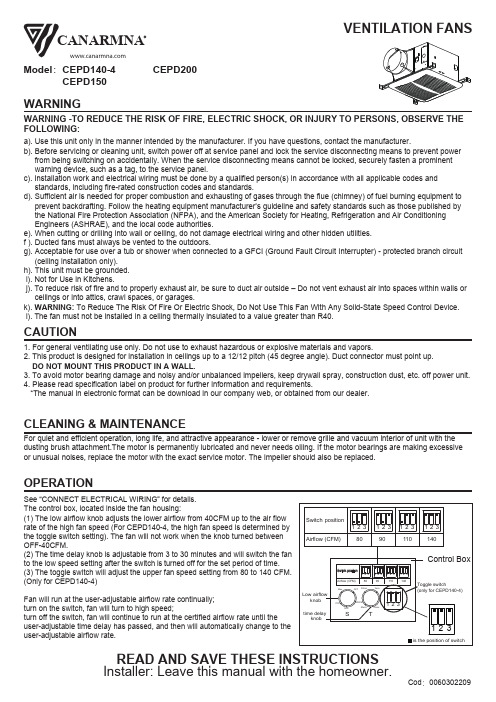
WARNINGREAD AND SAVE THESE INSTRUCTIONS CAUTIONCLEANING & MAINTENANCEOPERATIONFor quiet and efficient operation, long life, and attractive appearance - lower or remove grille and vacuum interior of unit with the dusting brush attachment.The motor is permanently lubricated and never needs oiling. If the motor bearings are making excessive or unusual noises, replace the motor with the exact service motor. The impeller should also be replaced.Model :CEPD140-4a). Use this unit only in the manner intended by the manufacturer. If you have questions, contact the manufacturer.b). Before servicing or cleaning unit, switch power off at service panel and lock the service disconnecting means to prevent power from being switching on accidentally. When the service disconnecting means cannot be locked, securely fasten a prominent warning device, such as a tag, to the service panel.c). Installation work and electrical wiring must be done by a qualified person(s) in accordance with all applicable codes and standards, including fire-rated construction codes and standards.d). Sufficient air is needed for proper combustion and exhausting of gases through the flue (chimney) of fuel burning equipment to prevent backdrafting. Follow the heating equipment manufacturer’s guideline and safety standards such as those published by the National Fire Protection Association (NFPA), and the American Society for Heating, Refrigeration and Air Conditioning Engineers (ASHRAE), and the local code authorities.e). When cutting or drilling into wall or ceiling, do not damage electrical wiring and other hidden utilities. f ). Ducted fans must always be vented to the outdoors.g). Acceptable for use over a tub or shower when connected to a GFCI (Ground Fault Circuit Interrupter) - protected branch circuit (ceiling installation only). h). This unit must be grounded. i). Not for Use in Kitchens.j). To reduce risk of fire and to properly exhaust air, be sure to duct air outside – Do not vent exhaust air into spaces within walls or ceilings or into attics, crawl spaces, or garages.k). WARNING: To Reduce The Risk Of Fire Or Electric Shock, Do Not Use This Fan With Any Solid-State Speed Control Device. l). The fan must not be installed in a ceiling thermally insulated to a value greater than R40.1. For general ventilating use only. Do not use to exhaust hazardous or explosive materials and vapors.2. This product is designed for installation in ceilings up to a 12/12 pitch (45 degree angle). Duct connector must point up. DO NOT MOUNT THIS PRODUCT IN A WALL.3. To avoid motor bearing damage and noisy and/or unbalanced impellers, keep drywall spray, construction dust, etc. off power unit.4. Please read specification label on product for further information and requirements.*The manual in electronic format can be download in our company web, or obtained from our dealer.WARNING -TO REDUCE THE RISK OF FIRE, ELECTRIC SHOCK, OR INJURY TO PERSONS, OBSERVE THE FOLLOWING:S ee “CONNECT ELECTRICAL WIRING” for details.The control box, located inside the fan housing:(1) The low airflow knob adjusts the lower airflow from 40CFM up to the air flow rate of the high fan speed (For CEPD140-4, the high fan speed is determined by the toggle switch setting). The fan will not work when the knob turned between OFF-40CFM.(2) The time delay knob is adjustable from 3 to 30 minutes and will switch the fan to the low speed setting after the switch is turned off for the set period of time. (3) The toggle switch will adjust the upper fan speed setting from 80 to 140 CFM.(Only for CEPD140-4)Fan will run at the user-adjustable airflow rate continually;turn on the switch, fan will turn to high speed;turn off the switch, fan will continue to run at the certified airflow rate until the user-adjustable time delay has passed, and then will automatically change to the user-adjustable airflow rate.VENTILATION FANSCEPD150CEPD200CANARMNA1. Do not use in a cooking area.2. Two ways to connect ductwork to a factory-shipped unit.PLAN THE INSTALLATIONASSEMBLY INSTRUCTIONS1.Sliding hanger bars have been provided, which allow the housing to bepositioned accurately anywhere between the framing. The bars span up to 24 in. and can be used on all types of framing: I-joist, standard joist, and truss construc-tion. Slide hanger bars onto housing and adjust as needed to fit between framing.2.Extend the hanger bars to the width of the framing. Position the ventilator with the bottom edge of the hanger bar tabs are flush with the bottom edge of the framing, holding the ventilator in place.Secure hanger bars to framing using one screw on each end of hanger bar.Select a proper hole and secure the hanger bars together using one screw.Hanger Bar3.INSTALL ROUND DUCTWORKConnect the round ductwork (not included) to the damper/duct connector,and run the ductwork to a roof or wall cap (not included). Using tape (not included), secure all the ductwork connections so that they are air tight.The ducting from this fan to the outside of building has a strong effect on the air flow, noise and energy use of the fan.Use the shortest, straightest duct routing possible for best performance, and avoid installing the fan with smaller ducts than recommended. Insulation around the ducts can reduce energy loss and inhibit mold growth. Fans installed withexisting ducts may not achieve their rated air flow.CONNECT ELECTRICAL WIRINGINSTALL GRILLERun 120 V AC house wiring to the location of the fan. Use only UL-approved connectors (not included) to attach the house wiring to the wiring plate. Refer to the wiring diagram, and connect the wires as shown.Install ceiling material to complete the ceiling construction. Then, cut around the fan housing.To attach the grille assembly to the fan housing. Pinch the grille springs on the sides of the grille assembly, and position the grille into the housing with the grille springs in the appropriate slots. Push the grille assembly towards the ceiling to secure.SERVICE PARTSPARTPART NAMEQty.12349101112a HousingWiring plate Damper / Duct Connector Screw 121111114b Screw 5c Screw 4dScrew6Grille Assembly (includes part 2)51Blower61Blower Wheel 71Motor Plate 84MotorGrille Spring WARNING: Ensure that the fan is switched off from the supplymains before replacing.Wire Panel / Harness Assemblye Hanger Bar KitControl Box * Blower Assembly includes part 3, 4, 5, 6, 7, b, c91210d 11WARRANTYThis warranty covers all defects in workmanship or materials for:The mechanical and electrical parts contained in this product, for a period of 12 months, from the date of purchase. You must keep and be able to provide your original sales receipt as proof of the date of purchase. This warranty is covered the original retail purchaser of this product. The manufacturer will repair or replace, in your home, any mechanical or electrical part which proves defective in normal household use for a period of 12 months.THIS WARRANTY DOES NOT COVER:• Damages from improper installation• Damages from shipping• Damages from misuse, abuse, accident, alteration, lack of proper care and maintenance• Damages from service by persons other than an authorized dealer or service center.• Labor, service, transportation and shipping charges for the removal of defective parts and for installation of a replacement part, beyond the initial 12-month period.This warranty does not extend to fluorescent lamp starters and tubes.THIS LIMITED WARRANTY IS GIVEN IN LIEU OF ALL OTHER WARRANTIES, EXPRESSED OR IMPLIED, INCLUDING THE WARRANTIES OF MERCHANTABILITY AND FITNESS FOR A PARTICULAR PURPOSE. The remedy provided in this warranty is exclusive and is granted in lieu of all other remedies. This warranty does not cover incidental or consequential damages. Some states do not allow the exclusion of incidental or consequential damages, so this limitation may not apply to you. Some states do not allow limitations on how long an implied warranty lasts, so this limitation may not apply to you. This warranty gives you specific legal rights, and you may also have other rights, which vary from state to state.。
114-AM4系列微机保护装置操作说明书-V2.1-20171127

用途 型号 功能
电流采集 电压采集 开关量采集 继电器输出 保护功能 过流(三段、反时限) 零序过流(两段、反时限) 负序过流(两段、反时限)
重合闸 过负荷跳闸/告警
低频减载 后加速过流 过电压跳闸 低电压跳闸
FC 闭锁 控故障告警 非电量跳闸/告警 低电压告警 过电压告警 零序过压告警 PT 断线告警 自产零序过压告警 I 母/II 母低电压告警 I 母/II 母过电压告警 I 母/II 母零序过压告警 I 母/II 母自产零序过压告警 I 母/II 母 PT 断线告警 通讯规约
第五章 装置背部端子图及接线方法...........................................................................................11 1 电气接线图.........................................................................................................................11 2 接线方法.............................................................................................................................13
第二章 技术参数.............................................................................................................................3 1 额定参数...............................................................................................................................3 1.1 工作电源...................................................................................................................3 1.2 输入激励电压............................................................................................................3 1.3 输入激励电流(保护电流)....................................................................................3 1.4 频率............................................................................................................................3 1.5 开关量输入................................................................................................................3 1.6 开关量输出................................................................................................................3 2 正常工作环境条件...............................................................................................................3
众诚矿山自动化组合开关1140说明书

安装使用前请详细阅读使用该说明书QJZ-1600/1140-O 矿用隔爆兼本质安全型组合开关使用说明书泰安市众诚矿山自动化有限公司目录第一章概述--------------------------------------------------------------2 第二章总体结构及系统组成-------------------------------------- 4 第三章主要电气性能-------------------------------------------------7 第四章安装与接线----------------------------------------------------9 第五章操作说明----------------------------------------------- ----- 11 第六章使用和操作----------------------------------------------------22 第七章保养与维护----------------------------------------------------24 第八章包装、运输和贮存-------------------------------------------24 附录:1、电气原理图第一章概述1.1 产品特点QJZ-1600/1140-O矿用隔爆兼本质安全型组合开关(以下简称组合开关)采用工业专用可编程逻辑控制器(PLC)作为核心控制与保护元件,配以可编程10.4 英寸高清晰液晶显屏,组成目前最先进的矿用组合开关控制与保护系统。
加之良好的人性化设计,全中文人机交互式操作界面,具有技朮先进,操作简便的优点。
可编程逻辑控制器的使用使得组合开关之控制电路大大简化,极大地减少了开关硬件电路的故障率,提高了组合开关的可靠性。
与此同时,在不改变硬连接的情况下,通过修正程序,可方便地改变、增加组合开关的功能,这样即可在现场更好更快地适应煤矿用户根据实际运行工矿的需要而不断增长和变化的控制要求。
minuteman v14 pro parts 说明书

Table of ContentsTechnical Specifications (2)Safety Instructions (2)Chassis Assembly Upper (3)Chassis Assembly Upper Bill Of Material (4)Chassis Assembly Lower (5)Chassis Assembly Lower Bill Of Material (6)Minuteman Limited Warranty (7)ModelV14 PRO Model No.V14115P14"Current Max 9.5 AmpsVacuum motor power 1150 WTraction motor power 150 WWorking surface 14" (350 mm)Weight 14.8 LBSNoise level 68 dB(A)Voltage 120 / 60 HzElectronic card, motor blocking ProvidedTransmission Poly V BeltAir flow 106 cfm (50 I/s)Dustbag 61 cu. in. (6.5 l)Cable 50 ft (15 m)Protection 3-wire groundSuction104” of water (26 kpa)For Safety When Servicing or Maintaining Machine• Disconnect the power to the machine.• Avoid moving parts. Do not wear loose jackets, shirts, or sleeves when working on machine.• Do not clean machine with a pressure washer.• Authorized personnel must perform repairs and maintenance. Use Minuteman supplied replacement parts.Technical SpecificationsUpper Housing AssemblyLower Housing AssemblyMinuteman International Made Simple Commercial Limited WarrantyMinuteman International, Inc. warrants to the original purchaser/user that the product is free from defects in workmanship and materials under normal use. Minuteman will, at its option, repair or replace without charge, parts that fail under normal use and service when operated and maintained in accordance with the applicable operation and instruction manuals. All warranty claims must be submitted through and approved by factory authorized repair stations.This warranty does not apply to normal wear, or to items whose life is dependent on their use and care, such as belts, cords, switches, hoses, rubber parts, electrical motor components or adjustments. Parts manufactured by Minuteman are covered by and subject to the warranties and/or guarantees of their manufacturers. Please contact Minuteman for procedures in w arranty claims against thes e manufacturers.Special warn ing to pu rchaser -- Use of replacement filters and/or prefilters not manufactured by Minuteman or its designated licensees, w ill void all warranties expressed or implied. A potential health hazard exists w ithout original equipment replacement.All warranted items become the sole property of Minuteman or its original manufacturer, whichever the case may be. Minuteman disclaims any implied warranty, including the warranty of merchantability and the w arranty of fitness for a particular purpose. Minuteman assumes no responsibility for any special, incidental or consequential damages.This limited warranty is applicable only in the U.S.A. and Canada, and is extended only to the original user/purchaser of this product. C ustomers outside the U.S.A. and Canada should c ontact their local distributor for export warranty policies. Minuteman is not responsible for costs or repairs performed by persons other than those specifically authorized by Minuteman. T his warranty does not apply to damage from transportation, alterations by unauthorized persons, misuse or abuse of the equipment, use of non-compatible chemicals, or damage to property, or loss of income due to malfunctions of the product.If a difficulty develops w ith this machine, you should contact the dealer from whom it w as purchased.This w arranty gives you specific legal rights, and you may have other rights which vary from state to state. Some states do not allow the exclusion or limitation of special, incidental or c onsequential damages, or limitations on how long an implied warranty lasts, so the above exclusions and limitations may not apply to you.Cord Electric Group………. Three years parts, two years labor, ninety days travel (Not to exceed two hours) Ex ceptions……….Port-A-Scrub, one year parts, six months laborMPV 13, one year partsV-14, one year parts, one year laborMPV 14 and 18, two years parts, one year laborR apidAir blow er, one year parts, one year laborExplosion-Proof Vacuum, one year parts, one year laborX12 and X12H, one year parts, one year laborTRS 14, one year parts, one year laborBattery Operated Group….. Three years parts, two years labor, ninety days travel(Not to exceed two hours)Exc eptions……Sw eepers, one year parts, one year labor, ninety days travel(Not to exceed two hours)Internal Combustion Group….One year parts, one year labor, ninety day travel(Not to exceed two hours)Battery Chargers………………. ..One year replacementReplacement Parts……………..Ninety daysBatteries………………………….0-3 months replacement, 4-12 months pro-ratePolypropylene Plastic Tanks…Ten years, no additional labor。
1140-6使用说明书

使用前请认真阅读使用说明书QJZ-2×800/1140(660)-6矿用隔爆兼本质安全型组合式真空电磁起动器使用说明书山东博城机电有限公司2010年3月第一章概述1.1.型号含义及产品特征Q J Z —2×800 / 1140(660)— 6输出回路数额定电压 v额定电流 A真空隔爆兼本质安全型起动器·防爆型式:矿用隔爆兼本质安全型;·标志:Exd[ib]Ⅰ;·外壳由钢板焊接制成;·零部件有防锈防腐蚀处理;·紧固件有防松动处理;·外壳最小壁厚≥3mm;·快开门设置“严禁带电开盖”的警告牌;·试验、运行工况设电气连锁;·外壳接地。
1.2. 主要技术参数额定工作电压:额定电压 1140/660V;工作总电流:1600A;起动器2路电源进线,设两台隔离开关,每台所带电流之和≤630A,单速每回路只用单个驱动器最大电流400A,双速每回路单个驱动器最大电流 400A ;电流整定: 无级调整,调整范围0A~400A。
a 本安远控回路参数:U0:13VAC/ 8VDC, I0:110mAAC/15mADC;最大远控距离100m ;b 本安键盘回路参数:U0:5VDC,I0:30mADC;本安键盘回路单个按键工作电压:5VDC;本安键盘回路单个按键工作电流: 18mA DC。
1.3. 执行标准GB3836-2000 GB 14048.1-2006 Q/0883BCZ002-20101.4. 工作环境及适用条件QJZ-2×800/1140(660)-6型矿用隔爆兼本质安全型组合式真空电磁起动器(以下简称起动器)适用于煤矿井下和其它周围介质中含有甲烷与煤尘混合物的爆炸性气体环境中。
起动器在下列条件下应能正常工作:a)海拔高度不超过2000m;b)周围环境温度为-5︒C—+40︒C;c)周围环境湿度不大于95%(+25︒C);d)有甲烷与煤尘爆炸性气体的环境;e)无破坏绝缘材料及金属的气体环境中;f)无显著摇动与冲击震动的地方;g)与水平面的安装倾斜度不超过15︒;h)安装类别:Ⅲ类i)污染等级:3级。
MG 4 00 固定式煤气室内火器说明书
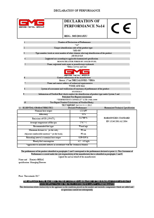
DECLARATION OF PERFORMANCEDECLARATION OFPERFORMANCE No14 REG. 305/2011/EU1 Number of Declaration of Performance .“14”2 Unique identification code of the product type .“MG 400”3 Type number, batch or serial number of other element allowing identification of the product .100/0010/0164 Suggested use according to applicable harmonized specification .ROOM HEATER FIRED BY SOLID FUEL5 Name, registered trade name or manufacturer trademark .“Gekas Savvas and Son ”6 Contact information of the manufacturer .Greece, 17 km THESSALONIKI - VERIA7 Name and contact address of authorized representative .WOOD AND GAS8 System of assessment and verification of constancy of performance of the product .SYSTEM 39 Information of Notified Bod which conduct the identification of product type under System 3 and .Published Test Reports/calculations“TERMOTEST CONSULT” LTD /(NB) 199910 Test Report Number/Calculations of Notified Body) .The performance of the product identified in paragraphs 2 and 3 correspond to the performance declared at point 11. This Statement ofPerformance is issued under the sale responsibility of the manufacturer that is identified in paragraphs 5 and 6.Signed for and on behalf of the manufacturerName and Dimitris GEKASqualification Managing DirectorPlace Thessaloniki 2017THE APPLIANCE TYPE HAS BEEN TESTED BY NOTIFIED LABORATORY OF THE EUROPEAN UNION AND HAVE.SUCCESSFULLY PASSED THE TESTS CONCERNING SAFETY & PERFORMANCEThis declaration relates exclusively to the appliance in the condition placed on the market and excludes components which are added and /or operations carried out subsequently。
9140中文说明书

9140钠离子分析仪使用说明书CONTROLS目录1、概述 (4)二、主要技术指标 (4)三、工作原理 (4)四、安装与接线 (5)五.操作 (10)六.维护 (17)七.仪器保存与保证期限 (19)8.仪器的成套与附件 (19)附录钠标准溶液的配制与保存 (20)特别提示▲用户在安装使用本仪器前,▲必须仔细阅读本说明书▲用户在安装使用本仪器前,▲必须严格按说明书中规定的方法程序操作,▲如不▲按规定的方法程序操作,▲我们不▲能保证仪器不▲被损坏▲仪器必须可靠接地▲控制器内部某些固态元器件易受静电影响,▲尽管不▲会使仪器立即失效,▲但会使仪器缩短寿命,▲操作时务必小心谨慎▲重视说明书中的“注意”标▲记一、概述 9140钠离子分析仪,是内含微处理的智能型仪器。
它配以相应的电极,对水溶液中钠离子浓度进行在线监测,可广泛应用于电厂、化工、环保、生化、海水淡化等行业。
仪器的主要特点如下:∙大面积彩色LCD显示;∙菜单式操作界面;∙触摸式键盘控制;∙自动温度补偿;∙自诊断功能;∙隔离直流输出;∙双限报警;∙具有独特的pH调节系统∙RSC485通讯口4二、主要技术指标1、量程:[Na+]:0.1µg/L ~ 1000 µg/L温度: 0 ℃~50 ℃2、仪器精度:[Na+]:±3%温度:±1 ℃3、输出信号:直流隔离输出:4~20 mA 负载不大于600Ω0~1 V 负载不小于200Ω4、报警:(1)报警点及死区可设置(2)继电器触点负荷:220V(交流),3A5、仪器使用条件(1)环境温度:0~40℃(2)相对湿度:≤85%(3)介质温度:5℃~50℃(4)电源电压: 220V±10%频率:50±0.5 Hz(5)无强磁场干扰,无强烈振动,无腐蚀性气体。
6、仪器外形尺寸:390m m×620 m m×205m m开孔尺寸:363 m m×593 m m5工作原理9140钠离子分析仪由电子单元和信号处理单元两部分组成。
1140说明书_20101215

ZJT系列矿用隔爆兼本质安全型变频调速装置使用说明书山西华鑫电气有限公司1序言感谢您选用山西华鑫电气有限公司的ZJT系列矿用隔爆兼本质安全型变频调速装置。
本产品是山西华鑫电气有限公司自主开发、生产的可靠性高、性能优异的变频器,采用高品质的元器件、优质材料并结合高新数字集成控制技术制造而成。
本手册提供用户安装配线、参数设定、故障诊断和故障排除、日常维护相关事宜,为确保能正确操作此系列变频器,发挥其优越性能,请在装机之前,详细阅读本使用手册,将本手册交于该机器的使用者,并请妥善保存。
本公司对客户提供全方位的技术支持。
如对于本变频器的使用存在疑难或有特殊要求,请与就近的办事处、客户服务中心或者经销商联系,也可直接与公司本部联系,我们将竭诚为您服务。
本公司一直致力于产品的不断改进和完善,故本系列变频器的相应资料(操作手册、宣传资料等)如有变动,恕不另行通知。
开箱检查注意事项开箱时,请认真确认以下内容:1.产品是否有破损,零部件是否有损坏、脱落等现象,主体是否有碰伤现象;2.本机铭牌所标注的额定值是否与您的订货要求一致;3.本公司在产品的制造及包装出厂方面,已严格检验,但若发现有某种遗漏,请速与本公司或供应商联系,我们将在第一时间为您解决。
山西华鑫电气有限公司地址:山西省阳泉市李家庄华鑫工业园邮编:0450082 安全注意事项为了确保您的人身和设备安全,在使用本装置之前,请务必仔细阅读本章内容,并在以后的搬运、安装、运行、调试与检修过程中遵照执行。
1. 安全标识定义本符号提示如果不按要求操作,可能导致死亡、重伤或严重的财产损失。
本符号提示如果不按要求操作,可能使身体受伤或设备损坏。
本符号说明操作时需注意的事项。
本符号提示一些有用的信息。
2. 安装注意事项 危险!请将本装置安装在金属等不可燃物体上,以免火灾的发生。
请将易燃物远离本装置,否则有发生火灾的危险。
严禁私自拆装、改装本装置,否则后果自负。
必须由具有专业资格的技术人员进行配线作业,以免触电危险。
理光1140L传真机说明书H3208651cs
FCC 要求
4
用户须知 (新西兰)
5
环境
6
电池和充电电池
6
产品
6
欧盟、瑞士和挪威的用户
6
所有其他用户
6
软件使用许可
7
定义
7
许可
7
所有权
7
有效期
7
质量担保
7
责任
7
发展
7
注册商标
8
通知
8
安装
9
场所条件
9
防范措施
9
安全信息
10
操作安全
10
电源
11
对于传真或电话
11
符号使用规则
11
终端描述
12
命令控制板
13
33 维护
49
保存 / 恢复通讯录 (智能卡选项)
33
服务
49
USB 闪存盘 ( 型号 MFP)
34
概要
49
USB 闪存盘使用
34
硒鼓更换
49
打印文件
34
智能卡问题
50
打印闪存盘内文件列表
34
清洁
50
打印闪存盘内的文件
34
扫描仪读取系统清洁
50
删除存储在闪存盘上的文件
34
打印机清洁
50
分析 USB 闪存盘内容
一致性声明
EEA 国家的用户须知
本产品符合欧洲议会和理事会于 1999 年 3 月 9 日公布的关于无线电与通讯终端设备指令及其符合性互认的 1999/5/EC 指令的基本要求和规定。
在 EEA 国家接入模拟 PSTN 的用户须知
此产品可以在所有 EEA 国家接入模拟 PSTN。本地 PSTN 的兼容性取决于软件交换设置。如果要将本产品重新安装到 其他国家,请与您的服务代表联系。 如果出现问题,请第一时间与您的服务代表联系。 Laser Facsimile / MFP Laser Facsimile:CE 一致性声明可从 Internet 上获得,其 URL 为: http://www.ricoh.co.jp/fax/ce_doc
KBZ-400(1140-660)操作手册封面(新版)
KBZ─400/1140(660) 矿用隔爆型真空馈电开关操作手册第一节安全指南2.3.1 基本原则2.3.1.1 常规要集中精力工作。
熟悉您自己的工作环境。
2.3.1.2 保护装备穿戴工作服和佩带个人保护装备。
通知您的伙伴:⏹您所在的确切地点;⏹您正在做的工作;⏹预计要工作多久。
2.3.1.3 先决条件只有在安全、正常情况下才能启动,启动前要检查所有的保护功能是否正常和各参数整定是否合适。
2.3.1.4 电压结构保持与馈电开关正常工作一致的电压结构。
2.3.2 储存和运输请从头仔细读完使用本操作手册,应采取必要的措施防止在运输工搬运过程中碰撞和剧烈振动。
遵守指定的储存方法。
长期不用时,应放在通风、防雨、防晒的仓库中,存放期限超过半年时应对馈电开关进行必要的外观检查,并进行必要的型式试验。
2.3.3.安装2.3.3.1 使用环境要求安装前检查使用环境,条件应符合本操作手册说明书上的要求。
2.3.3.2 馈电开关安装前的检查2.3.3.2.1 外观检查⏹检查馈电开关的型号及电压、电流等级是否与订货及实际使用一致(馈电开关在出厂时额定电压为馈电开关的最高电压,整定电流为馈电开关的最高额定电流);⏹检查馈电开关有无机械损伤;⏹馈电开关在安装完成打开馈电开关的主腔,检查控制变压器的电压等级跳线是否和电源电压相符;⏹检查电气元件在运输过程中有无受损或松动;⏹检查馈电开关壳内有无异物。
2.3.3.2.2通电检查⏹给开关正确的连接上电源线及地线,确认接线可靠无误后封闭好上接线腔盖板,并关上开关前门。
⏹给开关供电源,旋出前门机械闭锁螺杆,转动电源开关给开关控制回路供电,液晶显示屏亮,初始化完成后,按下起动按钮,检查动作是否正常可靠;⏹转动前门漏电试验和短路试验开关,检验模拟试验的可靠性;开关合闸后不做电流短路和过载试验。
⏹按下“确认”按钮,进入“现场测试”页面,进行各种保护试验,检查保护是否正常可KBZ─400/1140(660) 矿用隔爆型真空馈电开关操作手册靠,各故障指示灯是否正常。
安定宝4140安装手册

4140XMPT2防盗控制/通讯主机87防区 8个子系统 时间管理功能 16个继电器输出 128个使用者密码 224起事件记录ADEMCO 安定宝前言感谢您选用安定宝4140XMPT2防盗控制/通讯主机,希望我们先进的防盗系统会给您的生活、工作带来安全与方便!本安装编程指南适用于首次购买安装及曾使用过4140XMPT2防盗控制/通讯主机的安装工程人员。
本指南分五部分:安装说明、编程说明、系统操作与测试、安装例子与排错指南。
第一章安装说明包含对防盗系统原理、系统结构的描述。
使您对防盗系统基本概念及4140XMPT2主机的功能有一个初步了解。
第二章编程说明包含防盗系统操作原理、编程方法的描述。
详细说明每一个编程步骤,实现每一个功能的方法。
第三章系统操作与测试详细说明。
第四章安装例子分基础安装与扩充安装。
第五章排错指南针对一些常见故障提出改正方法。
目录前言 (I)目录 (II)第一章安装说明 (1)一.4140XMPT2主机系统结构。
(1)二.4140XMPT2主机性能说明。
(4)第二章编程说明 (6)一.防区类型 (6)二.布防方式与防区类型之关系: (7)三.编程概述: (7)编程预备知识: (8)四.编程模式编程说明: (9)1。
子系统部分选择功能(表格编程) (10)2。
#93菜单编程(菜单模式) (12)3。
控制选择功能(表格编程) (19)4。
防区选择功能(表格编程) (20)5。
无线部分选择功能(表格编程) (20)6。
通讯器选择功能 (21)7。
时间表与继电器输出选择功能: (24)8。
遥控编程选择功能(表格编程) (25)9。
事件记录选择功能(表格编程) (25)五.操作编程: (26)1。
时间管理编程: (26)2。
密码编程 (35)第三章系统操作与测试 (36)一。
键盘操作 (36)二。
测试系统 (38)第四章安装编程实例 (38)一.基础安装编程例子: (39)二.扩充功能安装编程例子: (40)第五章排错指南 (41)附页一:安装电路图 (45)附页二:通讯格式预设表 ............................................................................. 错误!未定义书签。
1140组合开关说明书

QJZ9215-3300、1140/660V(PLC)矿用隔爆兼本质安全型组合开关使用说明书山西长治贝克电气有限公司目录一、用途及概述 (1)二、使用条件 (1)三、主要技术参数和技术性能 (2)四、开关型号含义 (3)五、开关结构 (4)六、电气工作基本原理 (5)七、操作方法 (6)八、故障信息显示 (11)九、安装接线 (12)十、使用与维护 (13)十一、产品包装与保管 (14)十二、定货须知 (15)附录 (16)开关在使用前请认真阅读“使用说明书”一、用途及概述QJZ9215系列矿用隔爆兼本质安全型组合开关适用于含有爆炸性危险气体(甲烷)和煤尘的矿井中,在交流50HZ,电压1140(660V)线路中,对三相鼠笼式电动机或双绕组鼠笼式异步电动机的起动、停止进行控制和保护,并可在停止时方便地进行换向。
当设备出现过载,短路等故障时能自动切断电源并显示及记忆故障信号,开关还具有模拟漏电闭锁保护试验及短路保护试验功能,运行中能显示各支路状态参数。
本组合开关采用德国西门子公司S7-200可编程控制。
开关具有友好的人机界面,采用全中文液晶触摸屏显示及中文提示,更为直观,性能稳定,可靠性高,特别适合现场操作。
二、使用条件a、海拔不超过2000m;b、运行环境温度-25ºC-+40ºC;c、周围空气相对湿度不大于95%(+25ºC);d、在有沼气爆炸性混合物矿井中;e、在无显著摇动和冲击的地方;f、与垂直在的安装倾斜度不超过15º;g、在无破坏绝缘的气体或蒸气的环境中;h、在无滴水的地方;I、污染等级:3级;J、安装类别:Ⅱ类(负载水平级);三、主要技术参数和技术性能3.1主要技术参数:3.1.1 额定电压:660V、1140V或3300V3.1.2 额定频率:50HZ3.1.3 额定工作电流:当电压为660V/1140V时:总电流450A~1800A;单台隔离开关450 A;单台接触器80~400 A;当电压为3300V时:总电流1600A;单台隔离开关800A;单台接触器160A、400A、600 A;3.1.4 最大控制功率:在660 V,ηcosΦ=0.75时单回路为240KW在1140 V,ηcosΦ=0.75时单回路为500KW在3300 V,ηcosΦ=0.75时单回路为2000KW3.1.5 8小时工作制;3.1.6 允许电压波动范围:85~110%;3.1.7 电流整定范围:0~400A;3.1.8 机械寿命:接触器大于150万次;隔离换向开关大于0.6万次;3.1.9 电寿命:大于6万次;3.1.10 引入电缆外径:进线3个可穿入不大于Φ70(Φ80)mm的橡套电缆;出线4~8个,可穿入不大于Φ70(Φ80)mm橡套电缆;控制线6~8个,可穿入不大于Φ23mm的橡套电缆;3.1.11 外型尺寸:长×宽×高=2800(3250)×880×990(mm)3.2技术性能:本组合开关具有短路,过载、断相、漏电闭锁、过、欠压等各种保护。
1410使用说明书

1410使⽤说明书HYP1410微机电动机综合保护监控装置使⽤说明书USERGUIDEZHEJIANG HUAYI ELECTRIC POWER AUTOMATION CO.,LTD⽬录1.适⽤范围 (4)2.装置功能及保护原理简述 (4)2.1 电⽓参数测量 (4)2.2速断保护 (4)2.3过热(过负荷)保护 (4)2.4 零序过流(接地)保护 (5)2.5负序过流(不平衡、断相或反相)保护 (5)2.6 低电压保护 (5)2.7⾃启动控制 (5)2.8启动时间过长保护 (5)2.9堵转保护 (5)2.10 实际启动电流及启动时间显⽰ (5)2.11过热跳闸记忆及强制复归 (5)2.12过热报警 (6)2.13熔断器熔断报警 (6)2.14 PT断线报警 (6)3.技术参数 (6)4.按键功能及操作⽅法 (7)4.1按键功能 (7)4.1.1“▼” 搜索键与功能键 (7)4.1.2“??” 进⼊修改状态及移动⼩数点键 (7)4.1.3“▲” 修改、操作键 (7)4.1.4“■信号复归”键 (7)4.2输⼊密码的⽅法: (7)4.3搜索⽅法(适⽤于定点显⽰和定值区的显⽰): (7)4.4密码种类 (7)5. 数码管的显⽰种类 (7)5.1 数码管显⽰说明 (7)5.2⼏种显⽰列表 (7)5.2.1循环显⽰(供运⾏⼈员使⽤) (8)5.2.2定点显⽰(供运⾏⼈员或调试⼈员⽤) (8)5.2.3进⼊定值区的显⽰(输⼊密码1111) (8)5.2.4有报警或预告时的显⽰: (9)6.调试⽅法(适⽤于调试⼈员及维护⼈员) (9)6.1查看、输⼊或修改保护定值: (10)6.2开关量的检查 (10)6.3保护继电器的出⼝检查 (10)ZHEJIANG HUAYI ELECTRIC POWER AUTOMA TION CO.,LTD36.4模拟量输⼊检查及精度检查 ......................................................................................................... 10 6.4.1电流校准.................................................................................................................................... 10 6.4.2电压校准.................................................................................................................................... 10 6.4.3零序电流校准........................................................................................................................... 10 6.5保护定值的整定⽅法与实例(可供定值计算⼈员和调试⼈员参考) ........................................ 11 6.5.1⼆次侧额定电流整定 .. (11)6.5.2启动时间整定 ........................................................................................................................... 11 6.5.3速断保护整定........................................................................................................................... 11 6.5.4过热保护整定........................................................................................................................... 11 6.5.5零序过流(接地)保护整定.................................................................................................. 11 6.5.6负序过流(不平衡、断相或反相)保护整定..................................................................... 11 6.5.7低压保护整定........................................................................................................................... 11 6.5.8⾃启动时间整定....................................................................................................................... 11 6.6保护试验.......................................................................................................................................... 11 6.6.1速断试验.................................................................................................................................... 12 6.6.2过热特性测试........................................................................................................................... 12 6.6.3堵转试验.................................................................................................................................... 13 6.6.4启动时间过长试验................................................................................................................... 13 6.6.5零序过流试验........................................................................................................................... 13 6.6.6负序过流试验........................................................................................................................... 14 6.6.7低电压试验............................................................................................................................... 14 6.6.8⾃启动试验............................................................................................................................... 15 6.6.9动作时间试验........................................................................................................................... 15 6.6.10 FC 回路熔断器熔断报警...................................................................................................... 15 6.6.11 PT 回路断线报警................................................................................................................... 15 6.6.12定值错误报警试验................................................................................................................. 15 7、机箱结构及接线图............................................................................................................................. 167.1机箱结构图与说明.......................................................................................................................... 16 7.3保护装置的端⼦图及端⼦接线说明............................................................................................ 178.运⾏⼈员注意事项及要求.................................................................................................................... 189.检修及维护............................................................................................................................................. 18 附录1:HYP1410微机电动机保护装置原理图................................................................................. 19 附录2:HYP1410微机电动机保护装置原理接线图 . (20)ZHEJIANG HUAYI ELECTRIC POWER AUTOMA TION CO.,LTD41.适⽤范围HYP1410微机电动机保护装置适⽤于⼯作电压为 0.4-10KV 的电动机,作为电动机的成套保护和监视报警装置。
1140十组合开关说明书讲解

8SKC9215-3300、1140/660V(PLC)矿用隔爆型组合开关使用说明书山西长治贝克电气有限公司目录一、用途及概述 (1)二、使用条件 (1)三、主要技术参数和技术性能 (1)四、开关型号含义 (3)五、开关结构 (3)六、电气工作基本原理 (4)七、操作方法 (5)八、故障信息显示 (9)九、安装接线 (10)十、使用与维护 (11)十一、产品包装与保管 (12)十二、定货须知 (12)附录 (13)开关在使用前请认真阅读“使用说明书”一、用途及概述8SKC9215系列矿用隔爆型组合开关适用于含有爆炸性危险气体(甲烷)和煤尘的矿井中,在交流50HZ,电压1140(660V)、3300V线路中,对三相鼠笼式电动机或双绕组鼠笼式异步电动机的起动、停止进行控制和保护,并可在停止时方便地进行换向。
当设备出现过载,短路等故障时能自动切断电源并显示及记忆故障信号,开关还具有模拟漏电闭锁保护试验及短路保护试验功能,运行中能显示各支路状态参数。
本组合开关采用德国西门子公司S7-200可编程控制。
开关具有友好的人机界面,采用全中文液晶触摸屏显示及中文提示,更为直观,性能稳定,可靠性高,特别适合现场操作。
二、使用条件a、海拔不超过2000m;b、运行环境温度-25ºC-+40ºC;c、周围空气相对湿度不大于95%(+25ºC);d、在有沼气爆炸性混合物矿井中;e、在无显著摇动和冲击的地方;f、与垂直在的安装倾斜度不超过15º;g、在无破坏绝缘的气体或蒸气的环境中;h、在无滴水的地方;I、污染等级:3级;J、安装类别:Ⅱ类(负载水平级);三、主要技术参数和技术性能3.1 主要技术参数:3.1.1 额定电压:660V、1140V或3300V3.1.2 额定频率:50HZ3.1.3 额定工作电流:当电压为660V/1140V时:总电流450A~1800A;单台隔离开关450 A;单台接触器80~400 A;当电压为3300V时:总电流1600A;单台隔离开关800 A;单台接触器160A、400A、600 A;3.1.4 最大控制功率:在660 V,ηcosΦ=0.75时单回路为240KW在1140 V,ηcosΦ=0.75时单回路为500KW在3300 V,ηcosΦ=0.75时单回路为2000KW 3.1.5 8小时工作制;3.1.6 允许电压波动范围:75~110%;3.1.7 电流整定范围:0~400A;3.1.8 机械寿命:接触器大于150万次;隔离换向开关大于0.6万次;3.1.9 电寿命:大于6万次;3.1.10 引入电缆外径:进线3个可穿入不大于Φ70(Φ80)mm的橡套电缆;出线10个,可穿入不大于Φ70(Φ80)mm橡套电缆;控制线10个,可穿入不大于Φ23mm的橡套电缆;3.2 技术性能:本组合开关具有短路,过载、断相、漏电闭锁、过、欠压等各种保护。
合肥电子1410交换机系列产品介绍说明书

Product overviewThe HPE 1410 Switch Series comprises unmanaged Gigabit Ethernet and Fast Ethernet switches, designed for small businesses looking for entry-level low-cost networking solutions that come with a limited lifetime warranty. The series consists of nine models with flexible mounting options to meet different network switching needs. All models have quality of service (QoS) support and IEEE 802.3x flow control features that provide outstanding data efficiency.Simplified plug-and-play convenience is enabled by features such as auto-MDIX and auto-speed negotiation. Hewlett Packard Enterprise has innovated and combined the latest advances in silicon technology to bring you some of the most power-efficient switches—1410-24G-R, 1410-16, and 1410-24 models are advanced IEEE 802.3az-compliant unmanaged Gigabit and Fast Ethernet switches. The switches come with built-in green features and a limited lifetime warranty, making the series the right choice for organizations seeking a networking solution that’s both economical and reliable.A summary of the highlights of the 1410 Switch Series:• Unmanaged Gigabit Ethernet and Fast Ethernet switches • Green features for low power consumption • Fan-less design for silent operation • QoS support• Limited Lifetime warrantyHPE 1410 Switch SeriesData sheetFeatures and benefitsQoS• IEEE 802.1p prioritizationDelivers data to devices, based on the priority and type of traffic• DiffServ Code Point (DSCP) supportAllows real-time traffic prioritization, based on L3 TOS/DSCP parametersConnectivity• Auto-MDIXProvides automatic adjustments for straight-through or crossover cables on all 10/100 and 10/100/1000 portsPerformance• NEW Energy-efficient Ethernet supportSupports new IEEE 802.3az standard; and allows lower power consumption, when operated with IEEE-compliant client devices in 100 Mb/s mode only (JG708A, J9662A, and J9663A)• Half-/full-duplex auto-negotiating capability on every portDoubles the throughput of every port• NEW Jumbo frame supportAllows frames up to 9,216 bytes to be switched through the network (Gigabit Ethernet models)• Mini jumbo-frame supportAllows frames up to 2,048 bytes to be switched through the network, which supports large data transfers (J9662A and J9663A)Ease of use• UnmanagedProvides plug-and-play simplicity• Comprehensive LED display with per-port indicatorsProvides an at-a-glance view of the status, activity, speed, and full-duplex operation of the switches • Flow controlHelps ensure reliable communications during full-duplex operation• Auto-speed negotiationSelects individual port speed automatically, depending on client capabilities; removing the need for manual intervention enables simple plug-and-play operationFlexibility• Fan-less designEnables quiet operation for deployment in open spaces• NEW Internal power supplyDelivers operational convenience and an environment suitable for business operations (JG708A, J9561A, and JD986B)Warranty and support• Limited Lifetime WarrantySee /networking/warrantysummary for warranty and support information included with your product purchase.HPE 1410 Switch SeriesSPECIFICATIONS HPE 1410-8G Switch (J9559A)HPE 1410-16G Switch (J9560A)HPE 1410-24G-R Switch (JG708A) Ports8 RJ-45 autosensing 10/100/1000ports (IEEE 802.3 Type 10BASE-T,IEEE 802.3u Type 100BASE-TX,IEEE 802.3ab Type 1000BASE-T);Media Type: Auto-MDIX; Duplex:10BASE-T/100BASE-TX: half or full;1000BASE-T: full onlySupports a maximum of 8 autosensing10/100/1000 ports16 RJ-45 autosensing 10/100/1000ports (IEEE 802.3 Type 10BASE-T,IEEE 802.3u Type 100BASE-TX,IEEE 802.3ab Type 1000BASE-T);Media Type: Auto-MDIX; Duplex:10BASE-T/100BASE-TX: half or full;1000BASE-T: full onlySupports a maximum of 16 autosensing10/100/1000 ports24 RJ-45 autosensing 10/100/1000ports (IEEE 802.3 Type 10BASE-T,IEEE 802.3u Type 100BASE-TX,IEEE 802.3ab Type 1000BASE-T);Media Type: Auto-MDIX; Duplex:10BASE-T/100BASE-TX: half or full;1000BASE-T: full onlySupports a maximum of 24 autosensing10/100/1000 portsPhysical characteristicsWeight6.14(w) x 3.8(d) x 0.96(h) in(15.6 x 9.65 x 2.45 cm)0.74 lb (0.34 kg)8.21(w) x 4.41(d) x 1.73(h) in(20.85 x 11.2 x 4.4 cm) (1U height)1.43 lb (0.65 kg)17.32(w) x 6.81(d) x 1.73(h) in(44 x 17.3 x 4.4 cm) (1U height)6.61 lb (3 kg)Memory and processor 4 Kb EEPROM capacity;packet buffer size: 192 KB512 Kb flash; packet buffer size: 512 KB 1 MB flash; packet buffer size: 512 KBMounting Wall, desktop and under-table mounting Mounts in an EIA standard 19-inch telcorack (hardware included); wall, desktopand under-table mountingMounts in an EIA standard 19-inch telco rack(hardware included); desktop mountingPerformance100 Mb Latency1000 Mb LatencyThroughputSwitching capacityMAC address table size< 3.6 µs (LIFO 64-byte packets)< 1.2 µs (LIFO 64-byte packets)up to 11.9 million pps (64-byte packets)16 Gb/s4096 entries< 8.0 µs (LIFO 64-byte packets)< 3.6 µs (LIFO 64-byte packets)up to 23.8 million pps (64-byte packets)32 Gb/s8192 entries< 8.0 µs (LIFO 64-byte packets)< 3.6 µs (LIFO 64-byte packets)35.7 million pps (64-byte packets)48 Gb/s8192 entriesEnvironmentOperating temperatureOperating relative humidityNonoperating/Storage temperatureNonoperating/Storage relative humidityAltitudeAcoustic32°F to 104°F (0°C to 40°C)15% to 95% @ 104°F (40°C), noncondensing-40°F to 158°F (-40°C to 70°C)15% to 90% @ 149°F (65°C), noncondensingup to 10,000 ft (3 km)Power: 0 dB No fan32°F to 104°F (0°C to 40°C)15% to 95% @ 104°F (40°C), noncondensing-40°F to 158°F (-40°C to 70°C)15% to 90% @ 149°F (65°C), noncondensingup to 10,000 ft (3 km)Power: 0 dB No fan32°F to 104°F (0°C to 40°C)5% to 95% @ 104°F (40°C), noncondensing-40°F to 158°F (-40°C to 70°C)15% to 90% @ 149°F (65°C), noncondensingup to 16,404 ft (5 km)Power: 0 dB No fanElectrical characteristicsFrequencyMaximum heat dissipationVoltageCurrentMaximum power rating50/60 Hz41 BTU/hr (43.26 kJ/hr)100-240 VAC1.0 A12 WNotesMaximum power rating and maximumheat dissipation are the worst-casetheoretical maximum numbers providedfor planning the infrastructure withfully loaded PoE (if equipped), 100%traffic, all ports plugged in, and allmodules populated.The exact input voltage and frequencyrating are determined by the specificpower adaptor part number ordered.Please select the correct power adaptorcountry option.50/60 Hz44 BTU/hr (46.42 kJ/hr)100-240 VAC1.1 A13 WMaximum power rating and maximumheat dissipation are the worst-casetheoretical maximum numbers providedfor planning the infrastructure withfully loaded PoE (if equipped), 100%traffic, all ports plugged in, and allmodules populated.The exact input voltage and frequencyrating are determined by the specificpower adaptor part number ordered.Please select the correct power adaptorcountry option.50/60 Hz55 BTU/hr (58 kJ/hr)100-240 VAC0.3 A16 WMaximum power rating and maximumheat dissipation are the worst-casetheoretical maximum numbers providedfor planning the infrastructure withfully loaded PoE (if equipped), 100%traffic, all ports plugged in, and allmodules populated.This model provides internal powersupply. Please select the correct powercord country option.SPECIFICATIONS HPE 1410-8G Switch (J9559A)HPE 1410-16G Switch (J9560A)HPE 1410-24G-R Switch (JG708A)Safety CSA 22.2 No. 60950; EN 60950/IEC 60950; UL 60950-1 CSA 22.2 No. 60950; UL 60950-1;IEC 60950-1; EN 60950-1CSA 22.2 No. 60950; UL 60950-1;IEC 60950-1; EN 60950-1Emissions FCC Rules Part 15, Subpart B Class A FCC Rules Part 15, Subpart B Class A FCC Rules Part 15, Subpart B Class A ImmunityGenericENESDRadiatedEFT/BurstSurgeConductedPower frequency magnetic field Voltage dips and interruptions HarmonicsFlicker EN 55022 CISPR 22EN 55024, CISPR 24IEC 61000-4-2IEC 61000-4-3IEC 61000-4-4IEC 61000-4-5IEC 61000-4-6IEC 61000-4-8IEC 61000-4-11IEC 61000-3-2IEC 61000-3-3EN 55022 CISPR 22EN 55024, CISPR 24IEC 61000-4-2IEC 61000-4-3IEC 61000-4-4IEC 61000-4-5IEC 61000-4-6IEC 61000-4-8IEC 61000-4-11IEC 61000-3-2IEC 61000-3-3EN 55022 CISPR 22EN 55024, CISPR 24IEC 61000-4-2IEC 61000-4-3IEC 61000-4-4IEC 61000-4-5IEC 61000-4-6IEC 61000-4-8IEC 61000-4-11IEC 61000-3-2IEC 61000-3-3NotesIEEE 802.3az Energy Efficient Ethernet protocol is supported by the HPE 1410-24G-R (JG708A), HPE 1410-16 (J9662A) and HPE 1410-24 (J9663A) Switches.Services Refer to the Hewlett Packard Enterprisewebsite at /networking/servicesfor details on the service-level descriptionsand product numbers. For details aboutservices and response times in your area,please contact your local Hewlett PackardEnterprise sales office. Refer to the Hewlett Packard Enterprisewebsite at /networking/servicesfor details on the service-level descriptionsand product numbers. For details aboutservices and response times in your area,please contact your local Hewlett PackardEnterprise sales office.Refer to the Hewlett Packard Enterprisewebsite at /networking/servicesfor details on the service-level descriptionsand product numbers. For details aboutservices and response times in your area,please contact your local Hewlett PackardEnterprise sales office.(CONTINUED)HPE 1410 Switch SeriesSPECIFICATIONS HPE 1410-24G Switch (J9561A) HPE 1410-8 Switch (J9661A)HPE 1410-16 Switch (J9662A)Ports22 RJ-45 autosensing 10/100/1000 ports (IEEE 802.3 Type 10BASE-T, IEEE 802.3u Type 100BASE-TX, IEEE802.3ab Type 1000BASE-T); Media Type: Auto-MDIX; Duplex: 10BASE-T/100BASE-TX: half or full; 1000BASE-T: full only2 dual-personality ports; each port can be used as either an RJ-45 10/100/1000 port (IEEE 802.3 Type 10BASE-T, IEEE 802.3u Type 100BASE-TX, IEEE 802.3ab 1000BASE-T Gigabit Ethernet) or an open mini-GBIC slot (for use with mini-GBIC transceivers)Supports a maximum of 24 Gigabit Ethernet ports8 RJ-45 autosensing 10/100 ports(IEEE 802.3 Type 10BASE-T, IEEE 802.3u Type 100BASE-TX); Duplex: half or full Supports a maximum of 8 autosensing 10/100 ports16 RJ-45 autosensing 10/100 ports(IEEE 802.3 Type 10BASE-T, IEEE 802.3u Type 100BASE-TX); Duplex: half or full Supports a maximum of 16 autosensing 10/100 portsPhysical characteristics Weight13.23(w) x 6.65(d) x 1.73(h) in (33.6 x 16.9 x 4.4 cm) (1U height)2.98 lb (1.35 kg)6.14(w) x 3.74(d) x 0.97(h) in (15.6 x 9.5 x 2.46 cm) 0.74 lb (0.34 kg)8.21(w) x 4.21(d) x 1.73(h) in(20.85 x 10.69 x 4.39 cm) (1U height)1.43 lb (0.65 kg)Memory and processor 512 Kb flash; packet buffer size: 512 KB 16 Kb EEPROM; packet buffer size: 96 KB 16Kb EEPROM; packet buffer size: 2 Mb MountingMounts in an EIA standard 19-inch telco rack (hardware included); wall, desktop and under-table mountingWall, desktop and under-table mountingMounts in an EIA standard 19-inch telco rack (hardware included) wall, desktop and under-table mountingPerformance 100 Mb Latency 1000 Mb Latency ThroughputSwitching capacity MAC address table size< 8.0 µs (LIFO 64-byte packets) < 3.6 µs (LIFO 64-byte packets)up to 35.7 million pps (64-byte packets) 48 Gb/s 8192 entries< 3.7 µs (LIFO 64-byte packets) up to 1.1 million pps (64-byte packets) 1.6 Gb/s 1024 entries< 10.6 µs (LIFO 64-byte packets) up to 2.3 million pps (64-byte packets)3.2 Gb/s 8192 entriesEnvironmentOperating temperature Operating relative humidityNonoperating/Storage temperature Nonoperating/Storage relative humidity Altitude Acoustic32°F to 104°F (0°C to 40°C)15% to 95% @ 104°F (40°C), noncondensing -40°F to 158°F (-40°C to 70°C)15% to 90% @ 149°F (65°C), noncondensing up to 10,000 ft (3 km) Power: 0 dB No fan 32°F to 104°F (0°C to 40°C)15% to 95% @ 104°F (40°C), noncondensing -40°F to 158°F (-40°C to 70°C)15% to 90% @ 149°F (65°C), noncondensing up to 10,000 ft (3 km) Power: 0 dB No fan 32°F to 104°F (0°C to 40°C)5% to 95% @ 104°F (40°C), noncondensing -40°F to 158°F (-40°C to 70°C)15% to 90% @ 149°F (65°C), noncondensing up to 16,404 ft (5 km)Power: 0 dB No fanSPECIFICATIONS HPE 1410-24G Switch (J9561A) HPE 1410-8 Switch (J9661A) HPE 1410-16 Switch (J9662A) Electrical characteristicsFrequencyMaximum heat dissipation VoltageDC voltageCurrentMaximum power rating 50/60 Hz75 BTU/hr (79.13 kJ/hr)100-240 VAC0.3 A22 WNotesMaximum power rating and maximumheat dissipation are the worst-casetheoretical maximum numbers providedfor planning the infrastructure withfully loaded PoE (if equipped), 100%traffic, all ports plugged in, and allmodules populated.This model provides internal powersupply. Please select the correct powercord country option.50/60 Hz13 BTU/hr (13.72 kJ/hr)100-240 VAC12 V0.3 A3.6 WMaximum power rating and maximumheat dissipation are the worst-casetheoretical maximum numbers providedfor planning the infrastructure withfully loaded PoE (if equipped), 100%traffic, all ports plugged in, and allmodules populated.The exact input voltage and frequencyrating are determined by the specificpower adaptor part number ordered.Please select the correct power adaptorcountry option.50/60 Hz13 BTU/hr (13.72 kJ/hr)100-240 VAC12 V0.3 A3.6 WMaximum power rating and maximumheat dissipation are the worst-casetheoretical maximum numbers providedfor planning the infrastructure withfully loaded PoE (if equipped), 100%traffic, all ports plugged in, and allmodules populated.The exact input voltage and frequencyrating are determined by the specificpower adaptor part number ordered.Please select the correct power adaptorcountry option.Safety CSA 22.2 No. 60950; UL 60950-1;IEC 60950-1; EN 60950-1UL 60950-1; CSA 22.2 60950-1;IEC 60950-1:2005;EN 60950-1:2006 + A11:2009UL 60950-1; CSA C22.2 60950-1;IEC 60950-1:2005;EN 60950-1:2006 + A11:2009Emissions FCC Rules Part 15, Subpart B Class A FCC Rules Part 15, Subpart B Class A FCC Rules Part 15, Subpart B Class A ImmunityGenericENESDRadiatedEFT/BurstSurgeConductedPower frequency magnetic field Voltage dips and interruptions HarmonicsFlicker EN 55022 CISPR 22EN 55024, CISPR 24IEC 61000-4-2IEC 61000-4-3IEC 61000-4-4IEC 61000-4-5IEC 61000-4-6IEC 61000-4-8IEC 61000-4-11IEC 61000-3-2IEC 61000-3-3EN 55022 CISPR 22EN 55024, CISPR 24IEC 61000-4-2IEC 61000-4-3IEC 61000-4-4IEC 61000-4-5IEC 61000-4-6IEC 61000-4-8IEC 61000-4-11IEC 61000-3-2IEC 61000-3-3EN 55022 CISPR 22EN 55024, CISPR 24IEC 61000-4-2IEC 61000-4-3IEC 61000-4-4IEC 61000-4-5IEC 61000-4-6IEC 61000-4-8IEC 61000-4-11IEC 61000-3-2IEC 61000-3-3NotesUse only supported genuine Hewlett Packard Enterprise mini-GBICs with your switch.IEEE 802.3az Energy Efficient Ethernet protocol is supported by the HPE 1410-24G-R (JG708A), HPE 1410-16 (J9662A) and HPE 1410-24 (J9663A) Switches.(CONTINUED)SPECIFICATIONS HPE 1410-24G Switch (J9561A) HPE 1410-8 Switch (J9661A) HPE 1410-16 Switch (J9662A)Services Refer to the Hewlett Packard Enterprisewebsite at /networking/servicesfor details on the service-level descriptionsand product numbers. For details aboutservices and response times in your area,please contact your local Hewlett PackardEnterprise sales office. Refer to the Hewlett Packard Enterprisewebsite at /networking/servicesfor details on the service-level descriptionsand product numbers. For details aboutservices and response times in your area,please contact your local Hewlett PackardEnterprise sales office.Refer to the Hewlett Packard Enterprisewebsite at /networking/servicesfor details on the service-level descriptionsand product numbers. For details aboutservices and response times in your area,please contact your local Hewlett PackardEnterprise sales office.(CONTINUED)HPE 1410 Switch SeriesSPECIFICATIONS HPE 1410-24 Switch (J9663A)HPE 1410-24-R Switch (JD986B)HPE 1410-24-2G Switch (J9664A) Ports24 RJ-45 autosensing 10/100 ports(IEEE 802.3 Type 10BASE-T, IEEE 802.3uType 100BASE-TX, IEEE 802.3abType 1000BASE-T); Duplex:10BASE-T/100BASE-TX: half or full;1000BASE-T: full onlySupports a maximum of 24 autosensing10/100 ports24 RJ-45 autosensing 10/100 ports(IEEE 802.3 Type 10BASE-T, IEEE 802.3uType 100BASE-TX, IEEE 802.3abType 1000BASE-T); Duplex:10BASE-T/100BASE-TX: half or full;1000BASE-T: full onlySupports a maximum of 24 autosensing10/100 ports24 RJ-45 autosensing 10/100 ports(IEEE 802.3 Type 10BASE-T, IEEE 802.3uType 100BASE-TX); Duplex: half or full2 RJ-45 autosensing 10/100/1000 ports(IEEE 802.3 Type 10BASE-T, IEEE 802.3uType 100BASE-TX, IEEE 802.3abType 1000BASE-T); Duplex:10BASE-T/100BASE-TX: half or full;1000BASE-T: full onlySupports a maximum of 24 autosensing10/100 ports plus 2 autosensing10/100/1000 portsPhysical characteristicsWeight13.23(w) x 6.65(d) x 1.73(h) in(33.6 x 16.89 x 4.39 cm) (1U height)2.98 lb (1.35 kg)17.32(w) x 6.81(d) x 1.73(h) in(44 x 17.3 x 4.4 cm) (1U height)4.41 lb (2.0 kg)13.23(w) x 6.65(d) x 1.73(h) in(33.6 x 16.89 x 4.39 cm) (1U height)2.98 lb (1.35 kg)Memory and processor16 Kb EEPROM; packet buffer size: 2 Mb8kb EEPROM; packet buffer size: 2 Mb 2 Kb EEPROM; packet buffer size: 2.5 MbMounting Mounts in an EIA standard 19-inch telcorack (hardware included); wall, desktopand under-table mountingMounts in an EIA standard 19-inchtelco rack (hardware included); desktopmountingMounts in an EIA standard 19-inch telcorack (hardware included); wall, desktopand under-table mountingPerformance100 Mb Latency1000 Mb LatencyThroughputSwitching capacityMAC address table size< 11 µs (LIFO 64-byte packets)up to 3.5 million pps (64-byte packets)4.8 Gb/s8192 entries< 11 µs (LIFO 64-byte packets)3.5 million pps (64-byte packets)4.8 Gb/s8192 entries< 5.6 µs (LIFO 64-byte packets)< 2.2 µs (LIFO 64-byte packets)up to 6.5 million pps (64-byte packets)8.8 Gb/s8192 entriesEnvironmentOperating temperatureOperating relative humidityNonoperating/Storage temperatureNonoperating/Storage relative humidityAltitudeAcoustic32°F to 104°F (0°C to 40°C) )15% to 95% @ 104°F (40°C), noncondensing-40°F to 158°F (-40°C to 70°C)15% to 90% @ 149°F (65°C), noncondensingup to 10,000 ft (3 km)Power: 0 dB No fan32°F to 104°F (0°C to 40°C)15% to 95% @ 104°F (40°C), noncondensing-40°F to 158°F (-40°C to 70°C)15% to 90% @ 149°F (65°C), noncondensingup to 10,000 ft (3 km)Power: 0 dB No fan32°F to 104°F (0°C to 40°C5% to 95% @ 104°F (40°C), noncondensing-40°F to 158°F (-40°C to 70°C)15% to 90% @ 149°F (65°C), noncondensingup to 16,404 ft (5 km)Power: 0 dB No fanSPECIFICATIONS HPE 1410-24 Switch (J9663A)HPE 1410-24-R Switch (JD986B)HPE 1410-24-2G Switch (J9664A) Electrical characteristicsFrequencyMaximum heat dissipation VoltageDC voltageCurrentMaximum power rating 50/60 Hz17 BTU/hr (17.93 kJ/hr)100-240 VAC12 V0.4 A4.8 WNotesMaximum power rating and maximumheat dissipation are the worst-casetheoretical maximum numbers providedfor planning the infrastructure withfully loaded PoE (if equipped), 100%traffic, all ports plugged in, and allmodules populated.The exact input voltage and frequencyrating are determined by the specificpower adaptor part number ordered.Please select the correct power adaptorcountry option.50/60 Hz21 BTU/hr (22 kJ/hr)100-240 VAC3.3 V1.1 A3.6 WMaximum power rating and maximumheat dissipation are the worst-casetheoretical maximum numbers providedfor planning the infrastructure withfully loaded PoE (if equipped), 100%traffic, all ports plugged in, and allmodules populated.This model provides an internal powersupply. Please select the correct powercord country option.50/60 Hz37 BTU/hr (39.03 kJ/hr)100-240 VAC12 V0.9 A10.8 WMaximum power rating and maximumheat dissipation are the worst-casetheoretical maximum numbers providedfor planning the infrastructure withfully loaded PoE (if equipped), 100%traffic, all ports plugged in, and allmodules populated.The exact input voltage and frequencyrating are determined by the specificpower adaptor part number ordered.Please select the correct power adaptorcountry option.Safety UL 60950-1; CSA 22.2 60950-1;IEC 60950-1:2005; EN 60950-1:2006 +A11:2009UL 60950-1; CSA 22.2 60950-1;IEC 60950-1:2005; EN 60950-1:2006 +A11:2009UL 60950-1; CSA 22.2 60950-1;IEC 60950-1:2005; EN 60950-1:2006 +A11:2009Emissions FCC Rules Part 15, Subpart B Class A FCC Rules Part 15, Subpart B Class A FCC Rules Part 15, Subpart B Class A ImmunityGenericENESDRadiatedEFT/BurstSurgeConductedPower frequency magnetic field Voltage dips and interruptions HarmonicsFlicker EN 55022 CISPR 22EN 55024, CISPR 24IEC 61000-4-2IEC 61000-4-3IEC 61000-4-4IEC 61000-4-5IEC 61000-4-6IEC 61000-4-8IEC 61000-4-11IEC 61000-3-2IEC 61000-3-3EN 55022 CISPR 22EN 55024, CISPR 24IEC 61000-4-2IEC 61000-4-3IEC 61000-4-4IEC 61000-4-5IEC 61000-4-6IEC 61000-4-8IEC 61000-4-11IEC 61000-3-2IEC 61000-3-3EN 55022 CISPR 22EN 55024, CISPR 24IEC 61000-4-2IEC 61000-4-3IEC 61000-4-4IEC 61000-4-5IEC 61000-4-6IEC 61000-4-8IEC 61000-4-11IEC 61000-3-2IEC 61000-3-3NotesIEEE 802.3az Energy Efficient Ethernet protocol is supported by the HPE 1410-24G-R (JG708A), HPE 1410-16 (J9662A) and HPE 1410-24 (J9663A) Switches.(CONTINUED)Page 11 Data sheetSPECIFICATIONS HPE 1410-24 Switch (J9663A)HPE 1410-24-R Switch (JD986B)HPE 1410-24-2G Switch (J9664A)Services Refer to the Hewlett Packard Enterprisewebsite at /networking/servicesfor details on the service-leveldescriptions and product numbers. Fordetails about services and response timesin your area, please contact your localHewlett Packard Enterprise sales office.Refer to the Hewlett Packard Enterprisewebsite at /networking/servicesfor details on the service-leveldescriptions and product numbers. Fordetails about services and response timesin your area, please contact your localHewlett Packard Enterprise sales office.Refer to the Hewlett Packard Enterprisewebsite at /networking/servicesfor details on the service-leveldescriptions and product numbers. Fordetails about services and response timesin your area, please contact your localHewlett Packard Enterprise sales office.Standards and Protocols (applies to all products in series)General protocols IEEE 802.1p Priority IEEE 802.3ab 1000BASE-T GigabitEthernet over twisted pair (10/100/1000models only)IEEE 802.3i 10BASE-T Ethernet overtwisted pair IEEE 802.3u 100BASE-TX Fast Ethernet, 100BASE-FX with auto negotiation IEEE 802.3x Flow Control(CONTINUED)Data sheetHPE 1410 Switch Series accessoriesCables HPE 0.5 m Multimode OM3 LC/LC Optical Cable (AJ833A)HPE 1 m Multimode OM3 LC/LC Optical Cable (AJ834A)HPE 2 m Multimode OM3 LC/LC Optical Cable (AJ835A)HPE 5 m Multimode OM3 LC/LC Optical Cable (AJ836A)HPE 15 m Multimode OM3 LC/LC Optical Cable (AJ837A)HPE 30 m Multimode OM3 LC/LC Optical Cable (AJ838A)HPE 50 m Multimode OM3 LC/LC Optical Cable (AJ839A)HPE Premier Flex LC/LC Multi-mode OM4 2 fiber 1m Cable (QK732A)HPE Premier Flex LC/LC Multi-mode OM4 2 fiber 2m Cable (QK733A)HPE Premier Flex LC/LC Multi-mode OM4 2 fiber 5m Cable (QK734A)HPE Premier Flex LC/LC Multi-mode OM4 2 fiber 15m Cable (QK735A)HPE Premier Flex LC/LC Multi-mode OM4 2 fiber 30m Cable (QK736A)HPE Premier Flex LC/LC Multi-mode OM4 2 fiber 50m Cable (QK737A)HPE 1410-24G Switch (J9561A)HPE X121 1G SFP LC SX Transceiver (J4858C)HPE X121 1G SFP LC LX Transceiver (J4859C)HPE X111 100M SFP LC FX Transceiver (J9054C)Learn more at/networkingSign up for updatesRate this document© Copyright 2010-2011, 2013-2015 Hewlett Packard Enterprise Development LP. The information contained herein is subject to changewithout notice. The only warranties for Hewlett Packard Enterprise products and services are set forth in the express warranty statementsaccompanying such products and services. Nothing herein should be construed as constituting an additional warranty. Hewlett PackardEnterprise shall not be liable for technical or editorial errors or omissions contained herein.4AA1-1585ENW, November 2015, Rev. 6。
倒置式钥匙段 awareness rod SLN4140 产品说明书
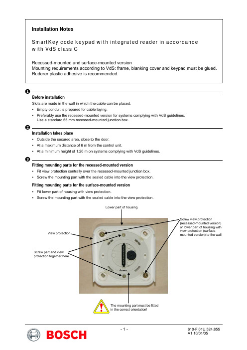
◆Before installationSlots are made in the wall in which the cable can be placed. ▪ Empty conduit is prepared for cable laying.▪ Preferably use the recessed-mounted version for systems complying with VdS guidelines. Use a standard 55 mm recessed-mounted junction box.Installation takes place▪ Outside the secured area, close to the door. ▪ At a maximum distance of 6 m from the control unit.▪ At a minimum height of 1.20 m on systems complying with VdS guidelines.♦Fitting mounting parts for the recessed-mounted version▪ Fit view protection centrally over the recessed-mounted junction box. ▪ Screw the mounting part with the sealed cable into the view protection. Fitting mounting parts for the surface-mounted version ▪ Fit lower part of housing with view protection.▪ Screw the mounting part with the sealed cable into the view protection.Screw part and view downThe mounting part must be fitted in the correct orientation!⌧Function test of the code keypad with reader▪ Insert the ribbon cable for the keypad into the socket on the mounting part as far as it will go. ▪ Push the rubber gasket into the socket on the mounting part until it is flush.▪ Wire up all the components in the system and carry out a function test. You will find all the necessaryinformation about wiring, function tests, commissioning, etc. in the installation manual for the SmartKey Arming device.▪Remove the keypad from the mounting part.⍓Glue in the frame (observe adhesive manufacturer's instructions for use)▪ Apply adhesive to the frame and mounting part at the positions marked in the illustrations. ▪Glue the frame and mounting part together.Glue in the blanking covers (observe adhesive manufacturer's instructions for use)▪ Apply adhesive to the keypad at the positions marked in the illustration and apply adhesive to the blanking covers at the opposite positions.▪Glue both blanking covers to the back of the keypad.Glue in the keypad (observe adhesive manufacturer's instructions for use)▪ Apply adhesive to the keypad and its mounting clips at the positions marked in the illustration. Apply adhesive to the mounting part and the frame at the positions marked in the illustration.▪ Create a connection with a ribbon cable between the keypad and the mounting part, see instruction 4 ▪ Glue the keypad and mounting part together.When inserting the keypad, the ribbon cable must not be folded, but just gently curved.Rear view of keypadFront view of keypad。