SY4064A说明书封皮2011
T6963C控制器中文使用说明书

杭州门市: 杭州市登云路 639 号杭州电子市场 2A095
0571-88256346 89902095(f)
北京分公司: 北京市海淀区中关村新中发电子市场 B1618
010-62051209 62000662 62568913 82036512(f)
网址:
背光
LED CCFL
● ● ● ● ● ●
● ● ●● ●● ●● ● ● ● ● ● ●● ●●
STN GRAY
● ●
● ● ●
● ●
显示模式
STN
STN
YELLOW BLUE
●
●
●
●
●
●
●
●
●
●
●
●
●
●
●
●
●
●
●
●
●
●
●
●
●
●
●
●
●
●
●
●
●
●
FSTN
● ● ●
● ● ●
● ●
清达光电技术有限公司
sales清达光电技术有限公司内藏t6963c控制器图形液晶模块使用手册目录使用须知3第一章点阵液晶图形模块汇总6第二章液晶模块的结构特点8第三章液晶模块供电说明9第四章液晶模块控制器介绍11第五章液晶模块指令系统16第六章液晶模块接口技术及测试程序21第七章液晶模块应用经验28附录一t6963c的内部字符集29附录二清达光电配套产品29附录三清达光电维修服务规范29清达光电技术有限公司电话
如果温度低于结晶温度,液晶就会结晶,如果温度过高,液晶将变成各向同性的
液体,破坏分子取向,使器件报废;
7. 用力按压显示部分,会产生异常显示。这时切断电源,稍待片刻,重新上电,即
AS4020中文版

限 (c) 试验时,从金属产品中萃取的金属一般是与饮用水接触产品的部件
不同于原版的内容如下: (i) 附录内容阐述的是换算系数的推导与应用. (ii) 对产品的测试是在高水温中进行.
有 (iii) 对诱变活动测试的校订内容,根据需要,为了使此测试与细胞毒素活动的测试更加准确,也 m 可将测试结果报告给此研究领域内的专家进行解释. 询 o (iv) 在水生微观有机物生长测试内容中取消了有关假单胞菌属氧化铜与大肠杆菌有机物的最 c 大允许量之规定. 咨 . 需要注意的是所有符合澳标 AS 3855(即与可饮用水接触的管类与供水类产品之适用性)的内 h 容,在 AS 3855 作为一个完整标准出版两年后会隶属于本标准.在此两年期间,一系列产品会依 务 s m 本标准进行测试,将这些测试结果之消息收集起来就可建立一个有关各类产品的数据库,并为 - o 标准中的其它测试提供精确数据,同时对产品可不经测试便能列出其清单,而且这样还可使标 商 a c 准经常受到审核,即使这样一来会超出澳标与新西兰标准与年审定一次的惯例,但该标准的修 s . 订版仍可发行.最终 CH/34 委员会将会每六个月开一次会,如果情况需要,也可是少于 6 个月来 萨 y h 审阅标准成员所需信息,从而对本标准进行适当的调整. h s “标准”与“非标准”在此标准中用来确定如何使用附录, 标准”附录只本标准内容的不可分割 上海海 www.www.hysa 部分,而“非标准”附录只用作提供信息与起指导作用.
AS04AD-A 安装说明说明书

AS04AD-A5014034202 2022-05-10EN Instruction Sheet TR Bilgi Dökümani TW 安裝說明 CN 安装说明ENThis is an OPEN TYPE module and therefore should be installed in an enclosure free of airborne dust, humidity, electric shock andvibration. The enclosure should prevent non-maintenance staff from operating the device (e.g. key or specific tools are required for operating the enclosure) in case danger and damage on the device may occur.FRCeci est un module ouvert et il doit donc être installé dans un coffret à l’abri des poussières, des vibrations et ne pas être exposé auxchocs électriques. Le boitier ou l’armoire doit éviter toute action d’un personnel autre que celui affecté à la maintenance de l’appareil (par exemple, clefs, outils spécifiques pour l’ouverture du coffret), ceci afin d’éviter tout accident corporel ou endommagement du produit).TRBu ürün AÇIK T İP bir modül olup toz, rutubet, elektrik şoku ve titre şimden uzak kapal ı yerlerde muhafaza edilmelidir. Yanl ış kullan ımsonucu ürünün zarar görmesini önlemek için yetkili olmayan ki şiler taraf ından ürüne müdahale edilmesini önleyecek koruyucu önlemler al ınmal ıd ır. (Ürünün bulundu ğu panoya kilit konulmas ı gibi).TW 本機為開放型(OPEN TYPE )機種,因此使用者使用本機時,必須將之安裝於具防塵、防潮及免於電擊∕衝擊意外之外殼配線箱內。
淞森 摩托车电池使用手册.pdf说明书
ISO9001、 ISO14001体系保证淞森摩托车电池使用手册●生产历史SM是MF密封免维护蓄电池,淞森公司自从1998年开始研制生产SM系列电池,此系列电池主要是出口为主;本产品已在欧洲的意大利、保加利亚、波兰以及东南亚的泰国、马来西亚、印度等国家和地区获得消费者认可,从2003年开始,淞森开始研究国内市场需求,开始在国内销售淞森牌免维护长寿命摩托车电池●特征免维护长寿命新一代摩托车电池三项国家专利独特的富液结构解决电池失水问题,确保了电池的长寿命自复位安全阀确保电池不易变形;干湿两用,结合干电池和水电池的优点,去除两者的不足,一方面可以延长电池寿命和储存期,另外一方面使电池便于维护和保养,极大地降低了退货效,使我们的退货率在5%以下.容量大,具有卓越的快速启动性能是一般电池所不具备的独特的铅钙配方,铅纯度达到99.9996%ISO9001国际质量体系和ISO14001环境体系保证●淞森摩托车电池使用手册尊敬的用户:感谢您选用了淞森电池,公司将用优质的后续服务来回馈您对淞森电池的支持。
※ 为了避免环境污染,本电池报废后,请交回专门的电池回收公司,或产家特约回收站、经销商。
★ 使用前请务必详细阅读本手册,以保证人身安全和正确使用。
● 安全1、电池请放置于儿童接触不到的地方;2、不要将电池的正负极接反,否则会造成电击火灾或事故;3、请勿自行拆修、分解或改造电池,否则电池内部的有毒物质对人和环境造成伤害;4、电池接线请用合适的导线,否则会成为火损或火灾的原因;5、请牢固地接好端子螺栓,否则会发热起火等;6、请勿将电池直接与交流电源连接;7、在使用过程中电池壳体温度超过60℃感觉烫手应立刻停止使用;8、电池不能接近明火或高温热源,更不能将电池抛入火中,高温季节严禁电池在阳光下直接暴晒;9、电池内的电解液为强腐蚀性酸液,切勿溅到皮肤或衣物上,如溅到皮肤、眼中、衣物上,须立即用清水冲洗,严重时须立即送医院治疗。
ERDN40-SPEC 2019-08-19 产品说明书

OTHERS DIMENSION
97*99*36mm (W*D*H)
PACKING
0.276Kg;45psc/14Kg/0.98CUFT
NOTE
1. All parameters NOT specially mentioned are measured at normal input , rated load and 25℃ of ambient temperature. 2. Derating may be needed over high ambient temperature. Please check the derating curve for more details. 3. The ambient temperature derating of 3.5℃/1000m with fanless models and of 5℃/1000m with fan models for operating altitude
9 19 36
12
14
24
29
48
60
INPUT VOLTAGE (V)
File Name:ERDN40-SPEC 2019-08-19
40A Enclosed Type Redundancy Module
Typical Application Notes
1. 1+1 Redundancy: Using 1 more PSU as the redundant unit
Note.3 5000 meters/OVC II
SAFETY STANDARDS WITHSTAND VOLTAGE
IEC62368-1, UL62368-1, EAC TP TC 004 approved IP/OP - Chassis : 0.5KVac ; IP/OP- Relay : 0.5KVac ; Relay - Chassis : 0.5KVac
Parker Autoclave Engineers Yoke Series 螺纹阀门说明说明书
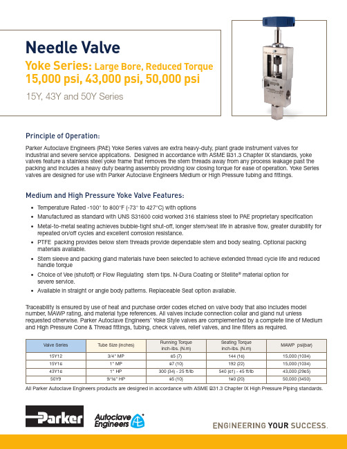
Principle of Operation:Parker Autoclave Engineers (PAE) Yoke Series valves are extra heavy-duty, plant grade instrument valves forindustrial and severe service applications. Designed in accordance with ASME B31.3 Chapter IX standards, yoke valves feature a stainless steel yoke frame that removes the stem threads away from any process leakage past the packing and includes a heavy duty bearing assembly providing low closing torque for ease of operation. Yoke Series valves are designed for use with Parker Autoclave Engineers Medium or High Pressure tubing and fittings.Medium and High Pressure Yoke Valve Features:• Temperature Rated -100° to 800°F (-73° to 427°C) with options• Manufactured as standard with UNS S31600 cold worked 316 stainless steel to PAE proprietary specification • Metal-to-metal seating achieves bubble-tight shut-off, longer stem/seat life in abrasive flow, greater durability for repeated on/off cycles and excellent corrosion resistance.• PTFE packing provides below stem threads provide dependable stem and body sealing. Optional packing materials available.• Stem sleeve and packing gland materials have been selected to achieve extended thread cycle life and reduced handle torque• Choice of Vee (shutoff) or Flow Regulating stem tips. N-Dura Coating or Stellite ® material option for severe service.• Available in straight or angle body patterns. Replaceable Seat option available.Traceability is ensured by use of heat and purchase order codes etched on valve body that also includes model number, MAWP rating, and material type references. All valves include connection collar and gland nut unlessrequested otherwise. Parker Autoclave Engineers’ Yoke Style valves are complemented by a complete line of Mediumand High Pressure Cone & Thread fittings, tubing, check valves, relief valves, and line filters as required.All Parker Autoclave Engineers products are designed in accordance with ASME B31.3 Chapter IX High Pressure Piping standards.Needle ValveYoke Series: Large Bore, Reduced Torque 15,000 psi, 43,000 psi, 50,000 psi15Y, 43Y and 50Y Series2Needle Valves: Y Series Yoke 02-0119SE 1119Y Series:Torque Reduction Yoke Valves* Cv values shown are for 2-way straight valve pattern. For 2-way angle pattern, increase Cv value 50% (Based on water). Formula for converting Cv to volumetric flow can be found in Technical Information section.** Maximum Allowable Working Pressure decreases as temperatures increase - see pressure/temperature rating guide in Technical Information section.Valve Packing Options:Standard Parker Autoclave Engineers valves with PTFE packing may be operated from 0°F to 450°F (-18° to 232°C). High and Cryogenic temperature packing and/or extended stuffing box are available for service from -100°F to 600°F (-73° to 315°C) by adding the following suffixes to catalog order number:-B Standard valve with Cryogenic trim materials and PTFE packing required when below 0° to -100°F (-18° to -73°C) -TG Standard valve with PTFE-Glass packing -100° to 600°F (-73° to 315°C) See also -B option above when below 0°F (-18°C) -GY Standard valve with Graphite Yarn packing 32° to 800°F (0° to 427°C)See “Technical Brochure “for Pressure/Temperature effect on temperatures above ambient.Y Series Flow CurveGeneralized Flow Coefficient Curves (C v )% of rated C vN u m b e r o f t u r n s o p e n10 20 30 40 50 60 70 80 90 1007654321015Y and 43Y Vee Stem50Y Vee Stem50YRegulating Stem15Y and 43Y Regulating StemTING3Needle Valves: Y Series Yoke 02-0119SE 1119Ordering Guide:For complete information on available stem types, optional connections and additional valve options, see Needle Valve Options section or contact your Sales Representative. Y Series valves are furnished complete with connectioncomponents, unless otherwise specified.Material of Construction:temperatures above ambient.Valve Manuals can be found on our website at ,Connection, Running and Seating Torques can be found in the product manual or in our Tools and Installation Catalog Section.4Needle Valves: Y Series Yoke 02-0119SE 1119G - Packing Gland mounting hole drill size • G1 - Bracket mounting hole size • H* - Dimension is with stem in closed position • All dimensions for reference only and subject to changeFor prompt service, Parker Autoclave stocks select products. Consult factory.Y Series Dimensions:Basic Repair Kits for 316 SS Material:Y Series Dimensions:G - Packing Gland mounting hole drill size • G1 - Bracket mounting hole size • H* - Dimension is with stem in closed position • All dimensions for reference only and subject to changeFor prompt service, Parker Autoclave stocks select products. Consult factory.5 Needle Valves: Y Series Yoke 02-0119SE 1119Stem Options:non-rotating, two-piece regulating stem which can be used forboth control and shut-off. While it is not as precise as the controlassociated with the MicroMetering stem, especially with smallerincrease service life.flows, it does offer substantially better control than the Vee stem.6Needle Valves: Y Series Yoke 02-0119SE 11197Needle Valves: Y Series Yoke 02-0119SE 1119ES Stem Extender:Stem extenders are offered for High and Low temperature operation or to extend through panel or barricade.To order valve with Stem Extender, add “ES-” and length (6", 12", 18", 24") to beginning of valve part number e.g. ES12-50Y9071. Other lengths to special order.To order Stem Extender only, provide valve model prefixe.g. ES12-50Y9. Handle not included – use same provided with original valve.Needle Valve Clam Shell Handle Lockout:(order separately using part numbers shown below, padlock not included)Clam Shell Handle locks are provided to lockout valves in open or closed position preventing unauthorized personnel from actuating valve during shutdown or emergency situations.This clamshell design is available in four (4) sizes dependent on handle length:P/N 90088 – 2.5" to 5.0" handle lengthP/N 90194 – 6.5" to 10" handle length! CAUTION !Do not mix or interchange component parts or tubing with those of other manufacturers. Doing so is unsafe and will void warranty.Parker Autoclave Engineers Valves, Fittings, and Tools are not designed to interface with common commercial instrument tubing and are designed to only connect with tubing manufactured toParker Autoclave Engineers AES specifications. Failure to do so is unsafe and will void warranty.Offer of SaleThe items described in this document are available for sale by Parker Hannifin Corporation, its subsidiaries or its authorized distributors. Any sale contract entered by Parker will begoverned by the provisions stated in Parker's standard terms and conditions of sale (copy available upon request).©2019 Parker Hannifin Corporation | Autoclave Engineers is a registered trademark of the Parker Hannifin Corporation Literature #: 02-0119SE November 2019ISO-9001 CertifiedInstrumentation Products Division Autoclave Engineers Operation 8325 Hessinger Drive Erie, PA 16509-4679Tel: 814 860 5700Fax: 814 860 /ipdInstrumentation Products Division Autoclave Engineers Operation, Houston15340 Vantage Parkway, East Houston, TX 77032Tel: 281 987 3828Fax: 281 987 2318Parker Hannifin Manufacturing Ltd.Instrumentation Products Division, EuropeRiverside RoadPottington Business ParkBarnstaple, UK, EX31 1NP , UK Tel: 44 1271 313131Fax: 44 1271 373636WARNINGFAILURE, IMPROPER SELECTION OR IMPROPER USE OF THE PRODUCTS AND/OR SYSTEMS DESCRIBED HEREIN OR RELATED ITEMS CAN CAUSE DEATH,PERSONAL INJURY AND PROPERTY DAMAGE.This document and other information from Parker Hannifin Corporation, its subsidiaries and authorized distributors provide product and/or system options for further investigation by users having technical expertise. It is important that you analyze all aspects of your application and review the information concerning the product or system in the current product catalog. Due to the variety of operating conditions and applications for these products or systems, the user, through its own analysis and testing, is solely responsible for making the final selection of the products and systems and assuring that all performance, safety and warning requirements of the application are met. The prod-ucts described herein, including without limitation, product features, specifications, designs, availability and pricing, are subject to change by Parker Hannifin Corporation and its subsidiaries at any time without notice.Needle Valves: Y Series Yoke 02-0119SE 1119Parker WorldwideNorth AmericaUSA – Corporate, Cleveland, OH Tel: +1 256 896 3000USA – IPD, Huntsville, AL Tel: +1 256 881 2040*****************USA – IPD, (Autoclave), Erie, PA Tel: +1 814 860 5700*******************CA – Canada, Grimsby, Ontario Tel +1 905-945-2274*********************South AmericaAR – Argentina, Buenos Aires Tel: +54 3327 44 4129 ******************BR – Brazil, Diadema, SP Diadema, SPTel: +55 11 4360 6700******************CL – Chile, Santiago Tel: +56 (0) 2 2303 9640******************MX – Mexico, Toluca Tel: +52 722 275 4200*******************Asia PacificAU – Australia, Dandenong Tel: +61 (0)2 9842 5150******************************CN – China, Shanghai Tel: +86 21 2899 5000*****************************HK – Hong Kong Tel: +852 2428 8008IN – India, MumbaiTel: +91 22 6513 7081-85ID – Indonesia, Tangerang Tel: +62 2977 7900********************JP – Japan, Tokyo Tel: +(81) 3 6365 4020******************KR – South Korea, Seoul Tel: +82 2 559 0400*******************MY – Malaysia, Selangor Tel: +603 784 90 800*******************SG – Singapore,Tel: +65 6887 6300*******************TH – Thailand, Bangkok Tel: +66 2 186 7000*********************TW – Taiwan, Taipei Tel: +886 2 2298 8987*************************VN – Vietnam, Hochi Minh City Tel: +848 382 508 56**********************Europe, Middle East, AfricaAE – UAE, Dubai Tel: +971 4 812 7100********************AT – Austria, Wiener Neustadt Tel: +43 (0)2622 23501-0*************************AT – Eastern Europe, Wiener Neustadt Tel: +43 (0)2622 23501 900****************************AZ – Azerbaijan, Baku Tel: +994 50 2233 458****************************BE/LU – Belgium, Nivelles Tel: +32 (0)67 280 900*************************BG – Bulgaria, Sofia Tel: +359 2 980 1344**************************BY – Belarus, Minsk Tel: +48 (0)22 573 24 00*************************CH – Switzerland, Etoy Tel: +41 (0) 21 821 87 00*****************************CZ – Czech Republic, Klecany Tel: +420 284 083 111*******************************DE – Germany, Kaarst Tel: +49 (0)2131 4016 0*************************DK – Denmark, Ballerup Tel: +45 43 56 04 00*************************ES – Spain, Madrid Tel: +34 902 33 00 01***********************FI – Finland, VantaaTel: +358 (0)20 753 2500*************************FR – France, Contamine s/Arve Tel: +33 (0)4 50 25 80 25************************GR – Greece, Athens Tel: +30 210 933 6450************************HU – Hungary, Budapest Tel: +36 223 885 470*************************IE – Ireland, DublinTel: +353 (0)1 466 6370*************************IT – Italy, Corsico (Ml)Tel: +39 02 45 19 21***********************KZ – Kazakhstan, Almaty Tel: +7 7273 561 000****************************NL – The Netherlands, Oldenzaal Tel: +31 (0)541 585 000********************NO – Norway, Stavanger Tel: +47 66 75 34 00************************PL – Poland, Warsaw Tel: +48 (0)22 573 24 00************************PT – Portugal, Leca da Palmeira Tel: +351 22 999 7360**************************RO – Romania, Bucharest Tel: +40 21 252 1382*************************RU – Russia, Moscow Tel: +7 495 645-2156************************SE – Sweden, Spånga Tel: +46 (0)8 59 79 50 00************************SK – Slovakia, Banská Bystrica Tel: +421 484 162 252**************************SL – Slovenia, Novo Mesto Tel: +386 7 337 6650**************************TR – Turkey, Istanbul Tel: +90 216 4997081************************UA – Ukraine, KievTel: +48 (0)22 573 24 00*************************UK – United Kingdom, Warwick Tel: +44 (0)1926 317 878********************ZA – South Africa, Kempton Park Tel: +27 (0)11 961 0700*****************************。
丹福斯 Vane Pumps AX438766743846en-000101 服务和零部件手册说明书
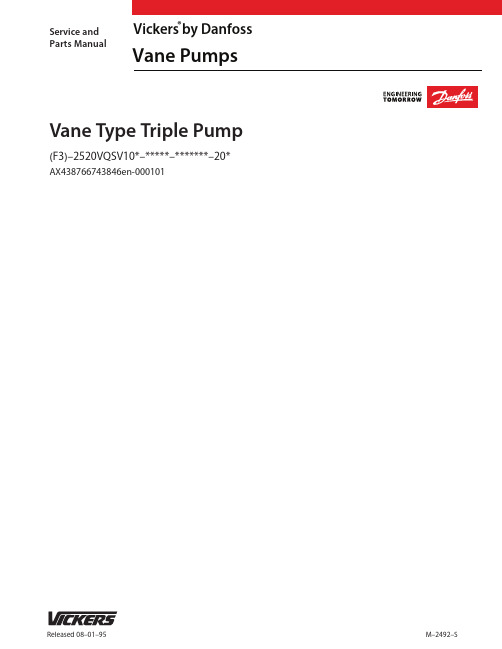
Released 08–01–95Service and Parts ManualM–2492–SVane Type Triple Pump(F3)–2520VQSV10*–*****–*******–20*Vickers by Danfoss®Vane PumpsAX438766743846en-000101V10F control valve S/ABolt (4 Req ’d) (See T able)T orque 41–61 N.m.(35–45 lb. ft.)590019“O” Ring 941038 Shim Kit Bolt (4 Req ’d) (See T able)T orque 41–61 N.m.(35–45 lb. ft.)320353 Plug590019“O” Ring 309199 Plug389460 Spring Control Valve S/A (See T able)386524 PistonV10P Cover Option (See T able)590019“O” Ring 2706 Seat 82800 Poppet Spring (See T able)307354 PlugV10S Cover Option(See T able)586581“O” Ring28422 Spring374343 Pressure Plate S/AVane Kit (See T able)Rotor (See T able)Ring (See T able)Pin (2 Req ’d) (See T able)586582 “O” Ring374865 Plug 590019“O” Ring 239766 SpringV10F Cover Option (See T able)Bolt (4 Req ’d)(See T able)T orque 41–61 N.m.(35–45 lb. ft.)374865 Plug229613233018232794232795232796232797232798232799233019233020923471923470923496923469923468923497923498295344432511295346SAE rated capacity (V10 cover end cartridge)USgpm Rotor V ane Kit (12 vanes)Ring Pin (V10S)Pin(V10F/V10P)Bolt (V10S)Bolt (V10F)Bolt (V10P)Cartridge Kit 1234567245616662179341111561278432509295344432511295346317681351247357286923499923500923501317674317675317676317677317678355641331813Pressure setting – V10P/V10F (Omit for V10S)250 psi 500 psi 750 psi 1000 psi 1250 psi 1500 psi 1750 psi 2000 psi 2250 psi 2500 psiCode A B C D E F G H J K Pressure setting V10P/V10FV10P Spring 252886228022822281V10 port connectionCode V10S Cover V10F Cover V10P Cover P R S Y T K 37286337286437286537782937954337285138826291017155023 Ring 396095“O” Ring 572823 Wear plate 586582 “O” Ring 245616662179341(See T able)Included in 25** VQ shaft end cartridge kit. Included in **20 VQ center cartridge kit.Included in V10 cover end cartridge kit.Included in seal kit 920166. (Kit contains F3components & both shaft seals.) Included in ex side plate kit; bronze face of plate must be installed toward the rotor. Kit also contains four seal packs. Assemble seal with spring loadedsealing member towards bearing. Seals to be completely wetted with oil prior to assembly.Install 419673 & 419672 sealing ring into body, then install cartridge kit.T orque 4–5 N.m. (40–50 lb.in.)NOTE: Body kit includes body, ball, and plug. (Ball and plug not shown)Primary portStr. thd Secondary port Str. thd.T ank port Str. thd CodeControlled ow rate, V10F & V10P(Omit for standard cover)Pump series designationModel CodeSpecial sealsPump series designation25**VQ – Shaft end pump **20VQ – Center pumpBody mounting angeS – SAE mounting per J –744 101–2V10 cover end pumpV10 pump cover optionsS – Standard coverF – Flow control and relief cover P – Priority valve and relief coverA – 4 bolt ange (inch thread)AM – 4 bolt ange (metric thread)VQ port connections (inlet & outlet #1 & #2)F3– Vition ”O”Rings and shaft seals SAE rated capacity(VQ shaft – end cartridge)10– 10 USgpm 12– 12 USgpm 14– 14 USgpm 16– 16 USgpm17– 17 USgpm 19– 19 USgpm 21– 21 USgpmCodeSAE rated capacity(V10 cover end cartridge)1– 1 USgpm 2– 2 USgpm 3– 3 USgpm 4– 4 USgpm5– 5 USgpm 6– 6 USgpm 7– 7 USgpmCode Code Shaft sealBlank – Single seal S – Double sealShaft type297 – All seriesDesign (Subject to change)Rotation(Viewed from shaft end of pump)Port orientation (Outlet #3or primary outlet)(Viewed from cover end of pump;refer to table on next page)3– 3 USgpm 4– 4 USgpm 5– 5 USgpm6– 6 USgpm 7– 7 USgpm 8– 8 USgpmCode Code Relief valve pressure setting,V10F & V10P(Omit for standard cover)A – 250 psiB – 500 psiC – 750 psiD – 1000 psiE – 1250 psiCode Code F – 1500 psi G – 1750 psi H – 2000 psi J – 2250 psi K – 2500 psiL – Left hand for counterclockwise R – Right hand for clockwiseCodeV10 port connections V10S standard covers and outlet # 3S – .750–16 Str. thd.P –1/2”–NPT thd.Y – .875–14 Str. thd.R – 1.062–12 Str. thd.CodeV10F ow/relief control cover Outlet # 3T ank port T – .750–16 Str. thd P – .750–16 Str. thd..750–16 Str. thd.1/2”–NPT thd.Code V10P priority control coversK – .5625–18.750–16.5625 –18Port orientation (Outlet #1)(Viewed from cover end of pump;refer to table on next page)Port orientation (Outlet #2)(Viewed from cover end of pump;refer to table on next page)5– 5 USgpm 6– 6 USgpm 8– 8 USgpm 9– 9 USgpm11– 11 USgpm 12– 12 USgpm 14– 14 USgpmCodeSAE rated capacity (VQ center cartridge)Code 81234576910111213141516171819Position view onlyPort orientation code131415NOTETo reverse cartridge kit rotation, remove the twoscrews and reverse the location of the inlet support plate and the outlet support plate. Reinstall the two screws hand tight. Use pump cover to align all sections of the cartridge. Carefully remove the cover and tighten the screws.When ordering spare cartridge parts, it is recommended they be obtained in cartridge kits. Kits are assembled and tested for either right or left hand rotation. If left hand rotation is required, it should be speci ed on parts order by adding su x ”L” to cartridge kit number.V10 cover can be assembled in any of four positions refer to drawing M –2005–S.Danfoss Power Solutions is a global manufacturer and supplier of high-quality hydraulic and electric components. We specialize in providing state-of-the-art technology and solutions that excel in the harsh operating conditions of the mobile off-highway market as well as the marine sector. Building on our extensive applications expertise, we work closely with you to ensure exceptional performance for a broad range of applications. We help you and other customers around the world speed up system development, reduce costs and bring vehicles and vessels to market faster.Danfoss Power Solutions – your strongest partner in mobile hydraulics and mobile electrification.Go to for further product information.We offer you expert worldwide support for ensuring the best possible solutions foroutstanding performance. And with an extensive network of Global Service Partners, we also provide you with comprehensive global service for all of our components.Local address:DanfossPower Solutions GmbH & Co. OHG Krokamp 35D-24539 Neumünster, Germany Phone: +49 4321 871 0DanfossPower Solutions ApS Nordborgvej 81DK-6430 Nordborg, Denmark Phone: +45 7488 2222DanfossPower Solutions (US) Company 2800 East 13th Street Ames, IA 50010, USA Phone: +1 515 239 6000DanfossPower Solutions Trading (Shanghai) Co., Ltd.Building #22, No. 1000 Jin Hai Rd Jin Qiao, Pudong New District Shanghai, China 201206Phone: +86 21 2080 6201Danfoss can accept no responsibility for possible errors in catalogues, brochures and other printed material. Danfoss reserves the right to alter its products without notice. This also applies to products already on order provided that such alterations can be made without subsequent changes being necessary in specifications already agreed.All trademarks in this material are property of the respective companies. Danfoss and the Danfoss logotype are trademarks of Danfoss A/S. All rights reserved.Products we offer:•Cartridge valves •DCV directional control valves•Electric converters •Electric machines •Electric motors •Gear motors •Gear pumps •Hydraulic integrated circuits (HICs)•Hydrostatic motors •Hydrostatic pumps •Orbital motors •PLUS+1® controllers •PLUS+1® displays •PLUS+1® joysticks and pedals•PLUS+1® operator interfaces•PLUS+1® sensors •PLUS+1® software •PLUS+1® software services,support and training •Position controls and sensors•PVG proportional valves •Steering components and systems •TelematicsHydro-GearDaikin-Sauer-Danfoss。
当宁消防网营口山鹰JB-QBZ2-YBZ127火灾报警控制器设计说明书
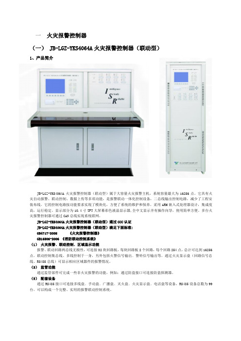
CAN2000通讯卡
与计算机管理系统或4064系列报警器通讯的接口
可选
多线联动控制盘
满足重要消防设备的多线制控制
必选
总线手动键盘
实现点对点启动设备——系统总线控制的外部设备
可选
24V/10A电源
为声光报警器等外部联动设备等供电
必选
4、内部接线图及输出端子图
显示界面图
5、安装布线
布线要求:
系统探测器二总线选用RVS-2×1.5mm2铜芯导线,回路最大线阻不大于30Ω。
系统输出的24V电源线选用BV铜芯导线,截面积≧2.5mm2
RS485、CAN通讯总线选用RVVP-2×1.5mm2铜芯导线。
系统接地及防雷标准请参考JB-LGZ-YKS4064火灾报警联动控制器。
6、分型产品
我公司还生产JB-LBZ-YBZ2032(壁挂式)尺寸:700X490X160、和JB-LTZ-YBZ2032(两空琴台式)等分型产品,并通过职能部门的检测,取得CCC认证证书。具体使用方法和技术特点等和JB-LGZ-YBZ2032相同,只是结构有所变化,这里就不在赘述。
如安装过程中必须布室外线,建议使用本公司生产的防雷系列模块。
7、分型产品
我公司还生产JB-LTZ-YKS4064A(两空琴台式式)分型产品,并通过职能部门的检测,取得CCC认证证书。具体使用方法和技术特点等和JB-LGZ-YKS4064A相同,只是结构有所变化,这里就不在赘述。
注意:系统设计图参照本设计指南后附页的图例。
(5)打印功能
微型热敏打印机实时打印报警信息,可打印全部信息或只打印火警信息、打印联动信息。
(6)历史记录存储
各种报警及操作信息均有详细的记录,全部记录、火警记录、联动记录分别存储,各为9000条。
Y t SNO 4062K KM 34安全继电器使用指南说明书
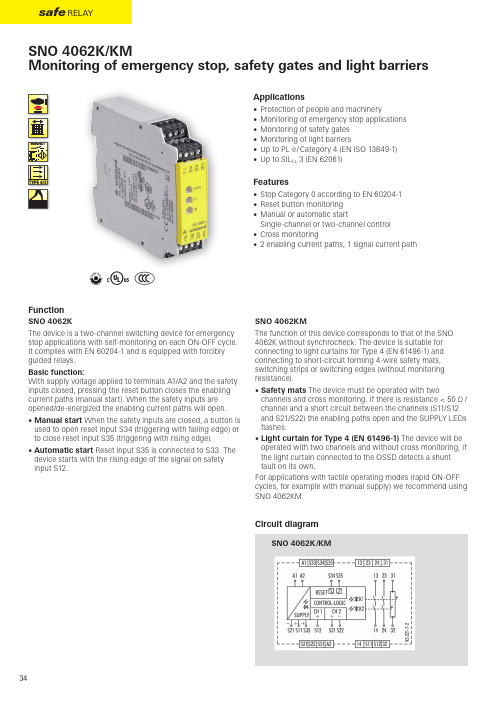
@ Y tSNO 4062K/KM34FunctionSNO 4062KThe device is a two-channel switching device for emergency stop applications with self-monitoring on each ON-OFF cycle. It complies with EN 60204-1 and is equipped with forcibly guided relays.Basic function:With supply voltage applied to terminals A1/A2 and the safety inputs closed, pressing the reset button closes the enabling current paths (manual start). When the safety inputs are opened/de-energized the enabling current paths will open.• Manual start When the safety inputs are closed, a button is used to open reset input S34 (triggering with falling edge) or to close reset input S35 (triggering with rising edge).• Automatic start Reset input S35 is connected to S33. The device starts with the rising edge of the signal on safety input S12.SNO 4062KMThe function of this device corresponds to that of the SNO 4062K without synchro c heck. The device is suitable for connecting to light curtains for Type 4 (EN 61496-1) and connecting to short-circuit forming 4-wire safety mats, switching strips or switching edges (without monitoring resistance).• Safety mats The device must be operated with twochannels and cross monitoring. If there is resistance < 50 Ω / channel and a short circuit between the channels (S11/S12 and S21/S22) the enabling paths open and the SUPPLY LEDs flashes.• Light curtain for Type 4 (EN 61496-1) The device will be operated with two channels and without cross monitoring, if the light curtain connected to the OSSD detects a shunt fault on its own.For applications with tactile operating modes (rapid ON-OFF cycles, for e xample with manual supply) we recommend using SNO 4062KM.Applications• Protection of people and machinery• Monitoring of emergency stop applications • Monitoring of safety gates • Monitoring of light barriers• Up to PL e / Category 4 (EN ISO 13849-1)• Up to SIL CL 3 (EN 62061)Features• Stop Category 0 according to EN 60204-1• Reset button monitoring • Manual or automatic startSingle-channel or two-channel control • Cross monitoring• 2 enabling current paths, 1 signal current pathCircuit diagram35safe relays a f e r e l a yOverview of devices | part numbersTechnical data1)If two-channel devices are installed as single channel, the value is halved.。
R404A安全技术说明书
致冷剂R404A安全技术说明书企业名称:浙江衢州联州致冷剂有限公司地址:浙江省衢州市柯城区联系电话:生效日期:2013年1月1日第一部分化学品及企业标识化学品中文名称:致冷剂R404A化学品英文名称:Refrigerant R404A化学品俗名或商品名:致冷剂R404A企业名称:浙江衢州联州致冷剂有限公司地址:浙江省衢州市巨化厂前路95号邮编:324004联系电话:企业应急咨询电话:全国通用消防电话:119传真号码:电子邮件地址:hca@SDS编码:SDS/LZ 01-2013首次编制日期: 2013年1月1日修订日期:2013年1月1日主要用途:可用于替代R22,主要用于低中温制冷系统限制用途:无资料。
第二部分危险性概述标签要素和警示性说明:象形图:信号词:危险危险性说明:在空气中不发生燃烧爆炸。
含压力下气体,如受加热可爆炸。
防范说明【预防措施】•戴防护手套•.作业后彻底清洗手等可能接触部位•禁止在工作场所内吸烟。
【事故响应】•皮肤接触:脱去污染衣着,用肥皂水和清水彻底冲洗皮肤至少15分钟。
如有冻伤,则必用温水擦洗。
若当时没有水,则在冻伤皮肤上敷上干净柔软的毛巾或其类似的东西。
一旦无好转,就医。
•火灾时:使用雾状水、大量水。
•食入:由于本物质之物理特性,一般不存在人体食入本物质的可能,即便发生对人体没有危险。
除非医生的指导下催食入者呕吐外,不得采用该措施。
•吸入:迅速脱离现场至空气新鲜处,保持呼吸道通畅。
如果呼吸困难,给输氧;如呼吸停止,立即进行人工呼吸。
立即呼叫就医。
•眼睛接触:提起眼睑,用流动清水或生理盐水冲洗。
就医【安全储存】•储存于阴凉、通风的库房。
远离火种、热源,禁止阳光直射。
库温不宜超过30℃,应与氧化剂、易燃物或可燃物分开存放,切忌混储。
【废弃处置】•根据国家和地方有关法规的要求处置或与厂商或制造商联系,确定处置方法。
•根据国家有关法规控制排放。
主要症状:冻伤,皮肤会发红,严重时会起泡。
R404A 安全技术说明书 ( MSDS )
R404A安全技术说明书(MSDS)第一部分化学品及企业标识化学品中文名称:HFC系混合冷媒R-404A 化学品中文俗名:制冷剂R-404A企业中文名称:上海澳宏化学品有限公司企业英文名称:Shanghai Aohong Chemical Co.,Ltd.地址:上海市嘉定华亭沪华东路333号邮编:201811公司网址: 传真号码:021—59974148企业应急电话:021—59974048安全技术说明书编号:AHC/MSDS-05-2011生效日期:2011年12月1日第二部分成分/组织信息纯品/混合物:混合物化学品名称:R-404A有害物成分:分子式分子量重量%CAS号四氟乙烷(R134a)CF3CH2F 102.0 4 811—97—2三氟乙烷(R143a)CH3CF384.04 52 420—46—2五氟乙烷(R125)CHF2CF3120.02 44 354—33—6第三部分危害性概述危险性类别:第2.2类不燃气体侵入途径:吸入、皮肤、眼睛接触损害,因常温常压下为气体,一般没有食入。
健康危害:与火接触火被加热时,可能分解放出CO、CO2、HF、COF2等有害物质;液化气体泄漏汽化时,从周围大量吸热,可致皮肤冻伤;在密闭空间泄漏时,有导致窒息的可能性,因此房间等要充分通风换气;吸入高浓度的气体时,可能全身麻痹等类似症状;持续直接接触、吸入时,可能发生头昏头痛、迟钝、喘气、意识模糊、运动失调等暂时性神经麻痹、机能低下等症状,严重的可导致心律不齐甚至心跳停止。
环境危害:臭氧层破坏系数0(R11为1);地球温暖系数3800(以CO2的温暖系数等于1,以100年为积分期间)。
爆炸危险:本物质属不燃性的液化气体;容器在火中火受高热可能爆炸。
第四部分急救措施吸人:移至空气新鲜处。
如果症状持续,就医。
皮肤:立即用水冲洗皮肤,直到皮肤上的化学物质完全洗去。
若皮肤已被冻伤,则务必用温水(不是热水)擦洗(不是干擦)。
“探路者”系列氟利昂R404a气体报警器(网络版)

“探路者”系列氟利昂R404a气体报警器(网络版)“探路者”系列氟利昂R404a气体报警器(网络版)名称的由来是因气体报警器本身带有防爆声光报警器,当现场氟利昂R404a浓度泄漏到设置的报警值时现场声光报警器将进行报警提示。
另外该气体报警器同时还具有实时数据显示、检测浓度信号变送的功能。
“探路者”系列氟利昂R404a气体报警器(网络版)内部带有2组继电器(开关量信号),可以控制外接的声光报警器、风机、电磁阀等设备。
声光报警功能检测速度快多级标定功能零点自动校正物联网功能内置WIFI模块搭载第三代‘COVER’系列传感器模组工业级的EMC模组隔爆设计本安设计RoHS设计提醒和报警功能齐全超高清彩色显示屏操作指引双操作方式双语操作系统黑匣子功能“探路者”系列氟利昂R404a气体报警器(网络版)简介“探路者”系列氟利昂R404a气体报警器(网络版)名称的由来是因气体报警器本身带有防爆声光报警器,当现场氟利昂R404a浓度泄漏到设置的报警值时现场声光报警器将进行报警提示。
另外该气体报警器同时还具有实时数据显示、检测浓度信号变送的功能。
“探路者”系列氟利昂R404a气体报警器(网络版)内部带有2组继电器(开关量信号),可以控制外接的声光报警器、风机、电磁阀等设备。
“探路者”系列氟利昂R404a气体报警器(网络版)特点★声光报警功能:该产品自带防爆声光报警器,可实现声光报警功能。
★检测速度快:对比同行同类产品,检测速度快;★多级标定功能:可实现高精度检测的成熟技术,已经过市场多年验证;★零点自动校正:针对某些环境应用,仪表可实现零点自动校正功能;★物联网功能:可连接安帕尔服务器来实现手机和电脑远程监控、报警提醒和报警值设置等;★内置WIFI模块:可以在有WIFI信号覆盖的区域,实现信号无线传输;★搭载第三代‘COVER’系列传感器模组,部分具有温湿度监测与补偿功能;★工业级的EMC模组,应对严酷的现场环境干扰;★隔爆设计、本安设计、RoHS设计。
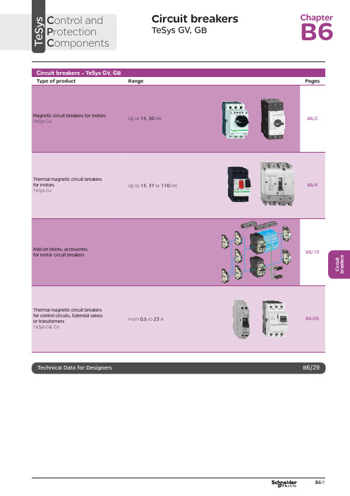
电磁保护设备TeSys GV系列产品参数表说明书
C i r c u i t b r e a k e r sCircuit breakersTeSys GV, GBC ontrol and P rotection C omponentsChapterB60.75g g 1.1g g 1.5375 2.533.5 LR2 K0308GV2LE071.1g g –––––– 2.533.5 LR2 K0308GV2LE071.5g g 1.5g g 3375451 LR2 K0310GV2LE08––– 2.2g g –––451 LR2 K0312GV2LE082.2g g 3501004375 6.378 LR2 K0312GV2LE103g g 410100 5.537510138 LR2 K0314GV2LE144g g 5.510100–––10138 LR2 K0316GV2LE14––––––7.537510138 LRD 14GV2LE14––––––937514170 LRD 16GV2LE165.515507.56751137514170 LR2 K0321GV2LE167.5155096751537518223 LRD 21GV2LE20915401147518.537525327 LRD 22GV2LE2211154015475–––25327 LRD 22GV2LE2215105018.54752237532416LRD 32GV2LE32(1) As % of Icu.g ) > 100 kA.GV2 LE10D F 526144.t i fC i r c u i t b r e a k e r s0.09––––––0.45LRD 03GV2L030.12g g –––0.37g g 0.638LRD 04GV2L040.18g g ––––––0.638LRD 04GV2L04––––––0.55g g 113LRD 05GV2L050.25g g ––––––113LRD 05GV2L05––––––0.75g g 113LRD 06GV2L050.37g g 0.37g g –––113LRD 05GV2L050.55g g 0.55g g 1.1g g 1.622.5LRD 06GV2L06–––0.75g g ––– 1.622.5LRD 06GV2L060.75g g 1.1g g 1.54100 2.533.5LRD 07GV2L07Example: GV3 L32 becomes GV3 L326.(1) As % of Icu. Associated current limiter or fuses, where required. See characteristics page B6/33.g > 100 kA.GV2 L10D F 526145.t i fGV3 L65D F 526146.t i fTeSys GVThermal-magnetic motor circuit breakers GV2 ME0.06gg––––––0.16…0.252.4GV2ME020.09g g––––––0.25…0.405GV2ME030.12 0.18g g g g – –– –– – 0.37 –g–g –0.40…0.638GV2ME040.25gg––– 0.55gg0.63…113GV2ME050.37 0.55 –g g –g g –0.37 0.55 0.75g g g g g g – 0.75 1.1– g g – g g 1…1622.5GV2ME060.75g g1.1gg1.5375 1.6...2.533.5GV2ME071.1 1.5g g g g 1.5 2.2g g g g 2.2 3 3 375 75 2.5 (4)51GV2ME082.2gg350100 43754...6.378GV2ME103 4g g g g 4 5.510 10100 100 5.5 7.5 3 375 756 (10)138GV2ME145.5 –15 –50 –7.5 – 6 –75 – 9 11 3 375 759…14170GV2ME167.5155096751537513…18223GV2ME209154011475 18.537517…23327GV2ME2111154015475 –––20…25327GV2ME22 (3)15105018.54752237524 (32)416GV2ME32Motor circuit breakers from 0.06 to 15 kW / 400 V, with lugsTo order thermal magnetic circuit breakers with connection by lugs, add the digit 6 to the end of reference selected above.Example: GV2 ME08 becomes GV2 ME086.Thermal magnetic circuit breakers GV2 ME with built-in auxiliary contact block With instantaneous auxiliary contact block (composition, see page B6/11):b GV AE1, add suffix AE1TQ to the motor circuit breaker reference selected above. Example: GV2 ME01AE1TQ .b GV AE11, add suffix AE11TQ to the motor circuit breaker reference selected above. Example: GV2 ME01AE11TQ .b GV AN11, add suffix AN11TQ to the motor circuit breaker reference selected above. Example: GV2 ME01AN11TQ .These circuit breakers with built-in contact block are sold in lots of 20 units in a single pack.(1) As % of Icu.(2) The thermal trip setting must be within the range marked on the graduated knob.(3) Maximum rating which can be mounted in enclosures GV2 MC or MP , please consult your Regional Sales Office. g > 100 kA.GV2 ME10D F 526134.t i fC i r c u i t b r e a k e r sTeSys GVTeSys protection componentsThermal-magnetic motor circuit breakers GV2 MEReferences0.06g g ––– 0.16…0.25 2.4GV2ME0230.09g g ––– 0.25…0.405GV2ME0330.120.18g g g g –––0.40…0.638GV2ME0430.250.37g g g g 0.37g g 0.63…113GV2ME0530.370.55g g g g 0.370.550.75g g g g g g 1…1.622.5GV2ME0630.75g g1.1g g 1.6…2.533.5GV2ME0731.11.5g g g g 1.52.2g g g g 2.5…451GV2ME0832.2g g 350100 4…6.378GV2ME10334g g g g 45.510101001006…10138GV2ME1435.515507.5675 9…14170GV2ME1637.515509675 13…18223GV2ME203911151540401147517…23327GV2ME2131115401547520 (25)327GV2ME223Contact blocksDescription Mounting Maximum number Type of contacts Sold in lots of Unitreference Instantaneous auxiliary contactsFront 1N/O + N/C 10GVAE113N/O + N/O 10GVAE203LH side2N/O + N/C 1GVAN113N/O + N/O1GVAN203AccessoryDescriptionApplicationSold in lots of Unitreference Cable end reducerFor connection of conductors from 1 to 1.5 mm 220LA9D99(1) For connection of conductors from 1 to 1.5 mm 2, the use of an LA9 D99 cable end reducer is recommended.(2) Maximum rating which can be mounted in enclosures GV2 MC or MP , please consult your Regional Sales Office (3) The thermal trip setting must be within the range marked on the graduated knob.g > 100 kA.GV2 ME pp 3D F 526135.t i fLA9 D99D F 533898.e p sTeSys GVReferencesTeSys protection componentsThermal-magnetic motor circuit breakersGV2 P, GV3 P and GV3 ME80GV2 P10D F 526137.t i fGV3 P65D F 526139.t i fGV3 P651D F 526140.t i fC i r c u i t b r e a k e r sTeSys GVReferences93610011181001581007.59707010010091150501001001115101010010012…20GV7RS20 2.0109113636100100111518181001001518.58810010015…25GV7RE25 2.0109117070100100111550501001001518.5101010010015…25GV7RS25 2.01018.53610018.522181810010022810025…40GV7RE40 2.01018.57010018.550100221010025…40GV7RS40 2.0102236100301810030810030…50GV7RE50 2.01522701003050100301010030 (50)GV7RS502.01537361004555181810010055810048...80GV7RE80 2.040377010045555050100100551010048...80GV7RS80 2.0404536100–1810075810060...100GV7RE100 2.0404570100–50100751010060...100GV7RS100 2.0405575353510010075903030100100901108810010090 (150)GV7RE1502.020557570701001007590505010010090110101010010090…150GV7RS150 2.02090110353510010011013216030303010010010016020088100100132…220GV7RE220 2.3509011070701001001101321605050501001001001602001010100100132…220GV7RS220 2.350(1) As % of lcu.TeSys protection componentsThermal-magnetic motor circuit breakers GV7 RGV7 RE40D F 526138.t i fGV7 RS220D F 526141.t i f0.12–0.120.180.18–0.370.40…0.6313GV2RT040.090.120.250.370.250.370.370.550.63…122GV2RT050.180.250.370.550.370.550.370.550.750.751.11…1.633GV2RT060.370.750.751.1 1.11.51.6…2.551GV2RT070.550.75 1.11.5 1.51.52.2 2.23 2.5…478GV2RT081.12.22.23344…6.3138GV2RT101.52.234445.5 5.57.56…10200GV2RT142.23 5.55.57.57.59119…14280GV2RT1647.57.5991513…18400GV2RT205.5911111118.517…23400GV2RT21(1) The thermal trip setting must be within the range marked on the graduated knob.GV2 RTD F 526142.t i fC i r c u i t b r e a k e r sblack handle, blue legend plate(1) The thermal trip setting must be within the range marked on the graduated knob.(2) Other accessories such as mounting, cabling and marking accessories are identical to those used for GV2 ME motor circuit breakers, see page B6/13.GV2 RTD F 526142.t i fD F 526340.e p sC i r c u i t b r e a k e r sTeSys GVDescription Mounting Maximum number Type of contacts Sold inlots of Unitreference Instantaneous auxiliary contactsFront (1)1N/O or N/C (2)10GVAE1N/O + N/C 10GVAE11N/O + N/O10GVAE20Side (LH)2N/O + N/C1GVAN11N/O + N/O1GVAN20Fault signalling contact + instantaneous auxiliary contact Side (3) (LH)1N/O (fault)+ N/O1GVAD1010+ N/C1GVAD1001N/C (fault)+ N/O1GVAD0110+ N/C1GVAD0101Short-circuit signalling contactSide (LH)1C/O common point1GVAM11(1 block on RH sideof circuit breaker GV2 ME)50 Hz GVAX11560 Hz GVAX116127 V60 Hz GVAX115220…240 V 50 Hz GVAX22560 Hz GVAX226380…400 V50 Hz GVAX38560 Hz GVAX386415…440 V 50 Hz GVAX415440 V60 Hz GVAX385Add-on contact blocksDescriptionMountingMaximum number Reference Visible isolation block (5)Front (1)1GV2AK00 (6)LimitersAt top(GV2 ME and GV2 P)1GV1L3Independent1LA9LB920(1) Mounting of a GV AE contact block or a GV2 AK00 visible isolation block on GV2 P and GV2 L .(2) Choice of N/C or N/O contact operation, depending on which way round the reversible block is mounted.(3) The GV AD is always mounted next to the circuit breaker.(4) To order an undervoltage trip: replace the dot (p ) in the reference with a U , example: GV AU025. To order a shunt trip: replace the dot (p ) in the reference with an S , example: GV AS025.(5) Visible isolation of the 3 poles upstream of circuit breaker GV2 P and GV2 L .Visible isolation block GV2 AK00 cannot be used with motor circuit breakers GV2 P32 and GV2 L32 (Ith max = 25 A).(6) Ie Max = 32 A.ReferencesTeSys protection componentsThermal-magnetic and magnetic motor circuit breakers GV2 with screw clamp connectionsAdd-on blocks and accessoriesCharacteristics:pages B6/89 and B6/94Dimensions, schemes:pages B6/70 to B6/82LA9LB920D B 126629.e p sC i r c u i t b r e a k e r sTeSys GVTerminal blockfor supply to one or more GV2 G busbar setsConnection from the top1GV1G09Can be fitted with current limiter GV1 L3 (GV2 ME and GV2 P)1GV2G05Cover for terminal block For mounting in modular panels10LA9E07Flexible 3-pole connection for connecting a GV2 to a contactor LC1-D09…D25 Centre distance between mounting rails: 100…120 mm10GV1G02Set of connections upstream/downstream For connecting GV2 ME to a printed circuit board 10GV2GA01“Large Spacing” adapter UL 508 type EFor GV2 P pp H7 (except 32 A)1GV2GH7Clip-in marker holders (supplied with each circuit breaker)For GV2 P , GV2 L, GV2 LE and GV2 RT (8 x 22 mm)100LA9D92ReferencesTeSys protection componentsThermal-magnetic and magnetic motor circuit breakers GV2 with screw clamp connectionsAccessoriesDimensions, schemes:pages B6/70 to B6/82D B 417942.e p sTeSys GVD B 126631.e p sD B 126630.e p sD B 126632.e p s7P B 106297_45.e p sExtended Rotary HandleAllows a circuit breaker or a starter-controller installed in back of an enclosure to be operated from the front of the enclosure.A rotary handle can be black or red/yellow, IP54 or IP65. It includes a function for locking the circuit breaker or the starter in the O (Off) or I (On) position(depending of the type of rotary handle) by means of up to 3 padlocks with a shank diameter of 4 to 8 mm. The extended shaft must be adjusted to use in different size enclosures. The IP54 rotary handle is fixed with a nut (Ø22) to make easierthe assembling. The new Laser Square tool brings the accuracy to align the circuit breaker and the rotary handle.device(padlocks not included)ReferencesTeSys protection componentsThermal-magnetic and magnetic motor circuit breakers GV2 with screw clamp connectionsC i r c u i t b r e a k e r sTeSys GVDescriptionMounting Maximum number Type of contacts Sold inlots of Unitreference Instantaneous auxiliary contactsFront1N/O or N/C (1)10GVAE1N/O + N/C 10GVAE11 (2)N/O + N/O10GVAE20 (2)Side (LH)2N/O + N/C1GVAN11 (2)N/O + N/O1GVAN20 (2)Fault signalling contact + instantaneous auxiliary contactFront 1N/O (fault)+ N/O1GVAED101 (2)N/O (fault)+ N/C1GVAED011 (2)Side (3) (LH)1N/O (fault)+ N/O1GVAD1010+ N/C1GVAD1001N/C (fault)+ N/O1GVAD0110+ N/C1GVAD0101Short-circuit signalling contact Side (LH)1C/O common point 1GVAM11(4)MountingVoltage ReferenceSide(1 block on RH side of circuit breaker)24 V 50 Hz GVA p 02560 Hz GVA p 02648 V 50 Hz GVA p 05560 Hz GVA p 05610050 Hz GVA p 107100…110 V 60 Hz GVA p 107110…115 V 50 Hz GVA p 11560 Hz GVA p 116120…127 V 50 Hz GVA p 125127 V 60 Hz GVA p 115200 V50 Hz GVA p 207200…220 V 60 Hz GVA p 207220…240 V 50 Hz GVA p 22560 Hz GVA p 226380…400 V 50 Hz GVA p 38560 Hz GVA p 386415…440 V 50 Hz GVA p 415415 V 60 Hz GVA p 416440 V 60 Hz GVA p 385480 V 60 Hz GVA p 415500 V 50 Hz GVA p 505600 V60 HzGVA p 505AccessoriesDescription Reference Sets of 3-pole 115 A busbars Pitch: 64 mm2 tap-off GV3 P pp and GV3 L pp GV3G2643 tap-off GV3 P pp and GV3 L pp GV3G364Cover “Large Spacing” UL 508 type E (Only one cover required on supply side)GV3 P ppGV3G66(1) Choice of N/C or N/O contact operation, depending on which way round the reversible block is mounted.(2) Contact blocks available in version with spring terminal connections. Add a figure 3 at the end of the references selected above. Example: GV AED101 becomes GV AED1013.(3) The GV AD pp is always mounted next to the circuit breaker.(4) To order an undervoltage trip: replace the dot (p ) in the reference with a U , example: GV AU025. To order a shunt trip: replace the dot (p ) in the reference with an S , example: GV AS025.Add-on blocks and accessoriesGV3 G66D F 537424.e p sTeSys GVD B 126637.e p sD B 126636.e p sD B 126632.e p s7P B 106297_45.e p sExtended Rotary HandleAllows a circuit breaker or a starter-controller installed in back of an enclosure to be operated from the front of the enclosure.A rotary handle can be black or red/yellow, IP54 or IP65. It includes a function for locking the circuit breaker or the starter in the O (Off) or I (On) position(depending of the type of rotary handle) by means of up to 3 padlocks with a shank diameter of 4 to 8 mm. The extended shaft must be adjusted to use in different size enclosures. The IP54 rotary handle is fixed with a nut (Ø22) to make easierthe assembling. The new Laser Square tool brings the accurency to align the circuit breaker and the rotary handle.For English 10-GVAPSEN For German 10-GVAPSDE For Spanish10-GVAPSES For Chinese 10-GVAPSCN For Portuguese 10-GVAPSPT For Russian 10-GVAPSRU For Italian10-GVAPSITD F 526342.e p sB6/21C i r c u i t b r e a k e r sTeSys GVfor locking the Start button (on open-mounted product)using up to 3 padlocks(padlocks to be ordered separately)External operator for mounting on enclosure door.Red Ø40 knob on yellow plate, padlockable in position O (with up to 3 padlocks). Door locked when knob in position I, and when knob padlocked in position O.GK3AP03(1) 1 voltage trip OR 1 fault signalling contact to be fitted inside the motor circuit breaker.Other versions24 to 690 V, 50 or 60 Hz voltage trips for circuit breakers GV3 ME80.Please consult your Regional Sales Office.ReferencesTeSys protection componentsMotor circuit breakers GV3 ME80 and GK3 EF80Add-on blocks and accessoriesCharacteristics:pages B6/89 and B6/92Dimensions:page B6/47B6/22D F 526344.e p sB6/23C i r c u i t b r e a k e r sTeSys GVThese allow remote indication of the circuit breaker contact states. They can be used for signalling, electrical locking, relaying, etc. They are available in two versions: standard and low level. They include a terminal block and the auxiliary circuits leave the circuit breaker through a hole provided for this purpose.They perform the following functions, depending on where they are located in the circuit breaker:Low levelGV7AB11Fault discrimination devicesThese make it possible to:b either differentiate a thermal fault from a magnetic fault,b or open the contactor only in the event of a thermal fault.VoltageReference a 24...48 and c 24…72 V GV7AD111 (1)z 110…240 VGV7AD112 (1)Electric tripsThese allow the circuit breaker to be tripped via an electrical control signal.b Undervoltage trip GV7 AUv Trips the circuit breaker when the control voltage drops below the tripping threshold, which is between 0.35 and 0.7 times the rated voltage.v Circuit breaker closing is only possible if the voltage exceeds 0.85 times the rated voltage. Circuit breaker tripping by a GV7 AU trip meets the requirements of IEC 60947-2.b Shunt trip GV7 ASTrips the circuit breaker when the control voltage rises above 0.7 times the rated voltage.b Operation (GV7 AU or GV7 AS)v When the circuit breaker has been tripped by a GV7 AU or AS, it must be reset either locally or by remote control. (For remote control, please consult your Regional Sales Office).v Tripping has priority over manual closing: if a tripping instruction is present, manual action does not result in closing, even temporarily, of the contacts.v Durability: 50 % of the mechanical durability of the circuit breaker.TypeVoltageReference Undervoltage trip48 V, 50/60 HzGV7AU055 (1)110…130 V, 50/60 Hz GV7AU107 (1)200…240 V, 50/60 Hz GV7AU207 (1)380…440 V, 50/60 Hz GV7AU387 (1)525 V, 50 HzGV7AU525 (1)Shunt trip48 V, 50/60 HzGV7AS055 (1)110…130 V, 50/60 Hz GV7AS107 (1)200…240 V, 50/60 Hz GV7AS207 (1)380…440 V, 50/60 Hz GV7AS387 (1)525 V, 50 HzGV7AS525 (1)(1) For mounting of a GV7 AD or a GV7 AU or AS.ReferencesTeSys protection componentsThermal-magnetic motor circuit breakers GV7 R with screw clamp connectionsAdd-on blocks and accessoriesCharacteristics:pages B6/51, B6/52 and B6/56Dimensions:pages B6/79 to B6/81Schemes:page B6/83B6/24B6/25C i r c u i t b r e a k e r sTeSys GVDescription ApplicationFor use on contactors Sold in lots of Unitreference Clip-on connectors for GV7 RUp to 150 A, 1.5…95 mm 2–3GV7AC021Up to 220 A, 1.5…185 mm 2–3GV7AC022Spreader 3-pole (1)To increase the pitch to 45 mm–1GV7AC03Terminal shields IP 405 (1)Supplied with sealing accessory–1GV7AC01Phase barriersSafety accessories used when fitting of shields is impossible –2GV7AC04Insulating screens Ensure insulation between the connections and the backplate –2GV7AC05Kits for combination with contactor (2)Allowing link between thecircuit breaker and the contactor. The cover provides protection against direct finger contactLC1 F115…F1851GV7AC06LC1 F225 and F2651GV7AC07LC1 D115 and D1501GV7AC08Replaces the circuit breaker front cover; secured by screws. It includes a device for locking the circuit breaker in the O (Off) position by means of up to 3 padlocks with a shank diameter of 5 to 8 mm (padlocks not included). A conversion accessory allows the direct rotary handle to be mounted on the enclosure door. In this case, the door cannot be opened if the circuit breaker is in the “ON” position. Circuit breaker closing is inhibited if the enclosure door is open.Description TypeDegree of protection Reference Direct rotary handleBlack handle, black legend plate IP 40GV7AP03Red handle, yellow legend plateIP 40GV7AP04Adapter plate (3)Four mounting direct rotary handle on enclosure doorIP 43GV7AP05Allows a circuit breaker installed in the back of an enclosure to be operated from the front of the enclosure. It comprises:b a unit which screws onto the front cover of the circuit breaker,b an assembly (handle and front plate) to be fitted on the enclosure door,b an extension shaft which must be adjusted (distance between the mounting surface and the door: 185 mm minimum, 600 mm maximum). It includes a device for locking the circuit breaker in the O (Off) position by means of up to 3 padlocks with a shank diameter of 5 to 8 mm (padlocks not included). This prevents the enclosure door from being opened.DescriptionTypeDegree of protection Reference Extended rotary handleBlack handle, black legend plate IP 55GV7AP01Red handle, yellow legend plateIP 55GV7AP02Allows circuit breakers not fitted with a rotary handle to be locked in the O (Off) position by means of up to 3 padlocks with a shank diameter of 5 to 8 mm (padlocks not included).Description ApplicationReference Locking deviceFor circuit breaker not fitted with a rotary handleGV7V01(1) Terminal shields cannot be used together with spreaders.(2) The kit comprises links, a protective shield and a depth adjustable metal bracket for the breaker.(3) This conversion accessory makes it impossible to open the door if the device is closed and prevents the device from being closed if the door is open.ReferencesTeSys protection componentsThermal-magnetic motor circuit breakers GV7 R with screw clamp connectionsAccessoriesGV7 AC07D F 537429.e p sGV7 AC08D F 537428.e p sDimensions:pages B6/79 to B6/81B6/260.5 6.63GB2DB051143GB2DB062263GB2DB073403GB2DB084503GB2DB095663GB2DB106833GB2DB1281083GB2DB14101383GB2DB16121653GB2DB20162203GB2DB21202703GB2DB22(1) Conforming to IEC 60947-1.GB2 CBppD F 526243.t i fGB2 CD ppD F 526244.t i fGB2 DBppD F 526245.t i fPresentation, selection :page B6/84Characteristics :pages B6/85 to B6/87Dimensions :page B6/88Schemes :page B6/88B6/27C i r c u i t b r e a k e r s(1) Conforming to IEC 60947-1.Accessories for circuit breakers GB2-CB, DB and CSDescriptionSold in lots of Unitreference Busbar set for supply to 10 GB2 DB or20 GB2 CB or GB2 CS with 2 connectors1GB2G210Supply connector 10GB2G01GB2 CS ppD F 526246.t i fPresentation, selection :page B6/84Characteristics :pages B6/85 to B6/87Dimensions :page B6/88Schemes :page B6/88B6/28B6/29B6/30TeSys GVCharacteristicsTeSys protection componentsMagnetic motor circuit breakers GV2 LE and GV2 LReferences:pages B6/2 and B6/3Dimensions:pages B6/43 to B6/47Schemes:page B6/48add-on contact blocks. Side by side mounting is possible up to 40 °C.(2) When mounting on a vertical rail, fit a stop to prevent any slippage.(1) As % of Icu.Average operating times at 20 °C related to multiples of the setting currentD F 534092.e p s1 3 poles from cold state2 2 poles from cold state3 3 poles from hot stateDynamic stressI peak = f (prospective Isc) at 1.05 Ue = 435 VD F 534093.e p s1 Maximum peak current2 32 A3 25 A4 18 A5 14 A6 10 A7 6.3 A8 4 A9 2.5 A 10 1.6 A11 Limit of rated ultimate breaking capacity on short-circuit of GV2 LE (14, 18, 23 and 25 A ratings).Dynamic stressI peak = f (prospective Isc) at 1.05 Ue = 435 VD F 534094.e p s1 Maximum peak current2 32 A3 25 A4 18 A5 14 A6 10 A7 6.3 A8 4 A9 2.5 A 10 1.6 A11 Limit of rated ultimate breaking capacity on short-circuit of GV2 LE (14, 18, 23 and 25 A ratings).Thermal limit in kA 2s in the magnetic operating zone Sum of I 2dt = f (prospective Isc) at 1.05 Ue = 435 V22Prospective Isc (kA)D F 534095.e p s1 32 A 2 25 A3 18 A4 14 A5 10 A6 6.3 A7 4 A8 2.5 A9 1.6 AThermal limit in kA 2s in the magnetic operating zone Sum of I 2dt = f (prospective Isc) at 1.05 Ue = 435 V22D F 534096.e p s1 25 A and 32 A 2 18 A3 14 A 4 10 A5 6.3 A6 4 A7 2.5 A8 1.6 AThermal limit in kA 2s in the magnetic operating zone Sum of I 2dt = f (prospective Isc) at 1.05 Ue = 435 V22D F 534097.e p s1 32 A (GV2 LE32)2 25 A and 32 A (GV2 L32)3 18 A4 14 A5 10 A6 6.3 A7 4 A8 2.5 A9 1.6 A10 Limit of rated ultimate breaking capacity on short-circuit of GV2 LE (14, 18, 23 and 25 A ratings).Average operating time at 20 °C without prior current flowx the setting current (Ir)D F 534098.e p s1 3 poles from cold state2 2 poles from cold state3 3 poles from hot stateA Thermal overload relay protection zoneB GV3 L protection zoneDynamic stressI peak = f (prospective Isc) at 1.05 Ue = 435 VProspective Isc (kA)D B 418280.e p s1 Maximum peak current2 GV3 L653 GV3 L504 GV3 L405 GV3 L326 GV3 L25Thermal limit in A 2sSum of I 2dt = f (prospective Isc) at 1.05 Ue = 435 V2Prospective Isc (kA)D B 418279.e p s1 GV3 L652 GV3 L503 GV3 L404 GV3 L325 GV3 L25TeSys GVDimensions, mountingD F 537440.e p sD F 537441.e p sD F 537444.e p sTeSys protection componentsMagnetic motor circuit breakers GV2 L and GV2 LETeSys GVDimensions, mounting TeSys protection componentsMagnetic motor circuit breakers GV2 L and GV2 LED B 127415.e p sD B 127414.e p sa b Mini Maxi Mini Maxi GV2 APN pp140250GV2 APN pp + GV APH02151250GV2 APN pp + GV APK11250434--GV2 APN pp + GV APH02 + GV APK11--250445TeSys GVDimensions,mounting Sets of busbars GV2 G445, GV2 G454, GV2 G472, with terminal block GV2 G05D F 537451.e p sGV2 G445224269314359GV2 G454260314368422GV2 G472332404476548D F 537452.e p sD F 537454.e p sGV2 G345 (3 x 45 mm)134GV2 G354 (3 x 54 mm)152TeSys protection componentsMagnetic motor circuit breakers GV2 L and GV2 LED F 537480.e psD F 537435.e p sD F 510637.e p sD F 510638.e p sD B 127416.e p sD B 127417.e p sa b Mini Maxi Mini Maxi GV3 APN pp189300--GV3 APN pp + GV APK12300481GV3 APN pp + GV APH03--200300GV3 APN pp + GV APH03 + GV APK12--300492TeSys GVSchemesTeSys protection componentsMagnetic motor circuit breakers GV2 L, GV2 LE, GV3 LD F 537474.e p sD F 537475.e p sD F 537476.e p sGV2 ME, GV2 P , GV3 ME, GV3 P and GV7 R motor circuit breakers are 3-pole thermal-magnetic circuit breakers specifically designed for the control and protection of motors , conforming to standards IEC 60947-2 and IEC 60947-4-1.Connection GV2GV2 ME and GV2 P circuit breakers are designed for connection by screw clamp terminals.Circuit breaker GV2 ME can be supplied with lugs or spring terminal connections.Spring terminal connections ensure secure, permanent and durable clamping that is resistant to harsh environments, vibration and impact and are even more effective when conductors without cable ends are used. Each connection can take two independent conductors.GV3GV3 circuit breakers feature connection by BTR screws (hexagon socket head), tightened using a n° 4 Allen key.This type of connection uses the Ever Link ® system with creep compensation (1) (Schneider Electric patent).This technique makes it possible to achieve accurate and durable tightening torque, in order to avoid cable creep.GV3 circuit breakers are also available with connection by lugs. This type of connection meets the requirements of certain Asian markets and is suitable for applications subject to strong vibration, such as railway transport.GV7GV7 circuit breakers: with connection by screw clamp terminals (for bars and lugs) and by clip-on connectors.OperationControl is manual and local when the motor circuit breaker is used on its own.Control is automatic and remote when it is associated with a contactor.GV2 ME and GV3 ME80Pushbutton control.Energisation is controlled manually by operating the Start button “I” 1.De-energisation is controlled manually by operating the Stop button “O” 2, or automatically by the thermal-magnetic protection elements or by a voltage trip attachment.GV2 P , GV3 P and GV7 Rb Control by rotary knob: for GV2 P and GV3 P b Control by rocker lever: for GV7 R.Energisation is controlled manually by moving the knob or rocker lever to position “I” 1.De-energisation is controlled manually by moving the knob or rocker lever to position “O” 2.De-energisation due to a fault automatically places the knob or rocker lever in the “Trip” position 3.Re-energisation is possible only after having returned the knob or rocker lever to position “O”.(1) Creep: normal crushing phenomenon of copper conductors, that is accentuated over time.GV2 MEwith screw clamp terminals124D F 526134.t i fGV2 MEwith spring terminals connections124D F 526135.t i fGV3 P1324D F 526136.t ifGV2 P1342D F 526137.t i fGV7 R132D F 526138.t i f。
pierce EMSA 试剂盒说明书
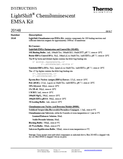
INSTRUCTIONSNumberDescription20148 LightShift Chemiluminescent EMSA Kit , contains components for 100 binding reactions and sufficient detection reagents for approximately 1000cm 2 of membrane Kit Contents:10X Binding Buffer , 1mL, 100mM Tris, 500mM KCl, 10mM DTT; pH 7.5, store at -20°C Biotin–EBNA Control DNA , 50μL , 10fmol/μL in 10mM Tris, 1mM EDTA; pH 7.5, store at -20°CThe 60 bp biotin end-labeled duplex contains the following binding site:5' BIOTIN-...TAGCATATGCTA (3)3'-…ATCGTATACGAT…-BIOTIN 5'Unlabeled EBNA DNA , 50μL , 2pmol/μL in 10mM Tris, 1mM EDTA; pH 7.5, store at -20°CThe ~25 bp duplex contains the following binding site:5'-...TAGCATATGCTA (3)3'-...ATCGTATACGAT (5)Epstein-Barr Nuclear Antigen (EBNA) Extract , 125μL , store at -20°C Poly (dI•dC), 125μL , 1µg/μL in 10mM Tris, 1mM EDTA; pH 7.5, store at -20°C 50% Glycerol , 500μL , store at -20°C 1% NP-40, 500μL , store at -20°C 1 M KCl , 1mL, store at -20°C 100mM MgCl 2, 500μL , store at -20°C 200mM EDTA pH 8.0, 500μL , store at -20°C5X Loading Buffer , 1mL, store at -20°CStabilized Streptavidin-Horseradish Peroxidase Conjugate , 1.5mL, store at 4°C Chemiluminescent Substrate, stable for 6 months at room temperature or 1 year at 4°C Luminol/Enhancer Solution , 80mLStable Peroxide Solution , 80mLBlocking Buffer , 500mL, store at 4°C 4X Wash Buffer , 500mL, store at 4°CSubstrate Equilibration Buffer , 500mL, store at room temperature or 4°CStorage : Upon receipt store individual components as indicated above. Box 20148X is shipped with dry ice. Box 89880 is shipped with an ice pack.LightShift ®Chemiluminescent EMSA KitTable of ContentsIntroduction (2)Procedure for Electrophoretic Mobility Shift Assay (EMSA) (3)A. Plan Binding Reactions (3)B. Prepare and Pre-Run Gel (4)C. Prepare and Perform Binding Reactions (5)D. Electrophorese Binding Reactions (5)E. Electrophoretic Transfer of Binding Reactions to Nylon Membrane (5)F. Crosslink Transferred DNA to Membrane (5)G. Detect Biotin-labeled DNA by Chemiluminescence (6)Additional Information Available from the Pierce Web Site (6)Troubleshooting (7)Related Thermo Scientific Products (7)References (8)IntroductionThe electrophoretic mobility shift assay (EMSA) has been used extensively for studying DNA-protein interactions.1-3 This technique is based on the fact that DNA-protein complexes migrate slower than non-bound DNA in a native polyacrylamide or agarose gel, resulting in a “shift” in migration of the labeled DNA band.The Thermo Scientific LightShift Chemiluminescent EMSA Kit uses a nonisotopic method to detect DNA-protein interactions. Biotin end-labeled DNA containing the binding site of interest is incubated with a nuclear extract or purified factor. This reaction is then subjected to gel electrophoresis on a native polyacrylamide gel and transferred to a nylon membrane. The biotin end-labeled DNA is detected using the Streptavidin-Horseradish Peroxidase Conjugate and the Chemiluminescent Substrate.Additional Materials Required•Biotin 3' or 5' end-labeled DNA target. Use existing end-biotinylated DNA targets or prepare them using a biotin end-labeling kit (see Related Thermo Scientific Products). Do not use probes with internal biotin labels (i.e., targetsbiotinylated at sites other than the 3' or 5' end, such results from random prime labeling methods) because the internal labels may inhibit binding of the DNA binding protein.•Positively charged nylon membrane (see Related Thermo Scientific Products)•5X TBE (450mM Tris, 450mM boric acid, 10mM EDTA, pH 8.3)•X-ray film (see Related Thermo Scientific Products) or CCD camera•UV lamp or crosslinking device equipped with 254nm bulbs or 312nm transilluminator•Electrophoresis apparatus•Electroblotter or capillary transfer apparatus•High-quality blotting paper•Circulating water bath•Plastic forceps•Polyacrylamide gel in 0.5X TBEProcedure for Electrophoretic Mobility Shift Assay (EMSA)This kit has been optimized for use with polyacrylamide mini (8 × 8 × 0.1cm) gels. For larger gels, adjust electrophoresis conditions and detection reagent volumes accordingly.A.Plan Binding Reactions•Understanding the Control EBNA SystemInclude a complete set of three reactions each time an EMSA is performed. These reactions and expected results for the Control Epstein-Barr nuclear antigen(EBNA) System, which is included with the kit, are described in Table 1.The Control EBNA System results reported in Table 1 were generated using binding reactions prepared according to Table 2. Each 20μL binding reaction contains 20 fmol of Biotin-EBNA Control DNA. Reactions were electrophoresed, transferred and detected according to the steps in Sections B-G of this protocol. If the kit is being used for the first time, perform the Control EBNA System reactions to verify that the kit components and overall procedure are working properly.Table 2. Binding reactions for Control EBNA System.Component Final AmountControl Reactions#1 #2 #3Ultrapure Water ---- 12μL11μL9μL 10X Binding Buffer (20148A) 1X 2μL2μL2μL 50% Glycerol (20148F) 2.5% 1μL1μL1μL 100mM MgCl2 (20148I) 5mM 1μL1μL1μL 1µg/μL Poly (dI•dC) (20148E)50 ng/µL 1μL1μL1μL 1% NP-40 (20148G) 0.05% 1μL1μL1μL Unlabeled EBNA DNA (20148C) 4 pmol ----- ----- 2μL EBNA Extract (20148D) 1 Unit ----- 1μL1μL Biotin–EBNA Control DNA (20148B) 20 fmol 2μL2μL2μL Total Volume ---- 20μL20μL20μL•Planning and optimizing the Test SystemAs with the Control EBNA System, a complete set of three reactions should be performed with the Test System. Use Table 3 as a guide for planning the Test System binding reactions. If specific binding conditions are not already known, use only minimal reaction components; e.g., 10X binding buffer and Poly (dΙ•dC), together with the biotin-labeled target DNA, protein extract and unlabeled DNA of the Test System.Nuclear protein extracts prepared using the Thermo Scientific NE-PER Nuclear and Cytoplasmic Extraction Reagents (see Related Thermo Scientific Products) are an excellent source of target protein. Use 2-3μL of NE-PER®Nuclear Extract per 20μL binding reaction. If a greater volume of NE-PER Extract is required, remove excess salts in the extract by dialyzing into a buffer containing 200mM salt (use a Slide-A-Lyzer®MINI Dialysis Unit; see Related Thermo Scientific Products) before use in the LightShift EMSA Kit.Optimization of the Test System can be achieved by adding other components supplied in the kit such as KCl,4, 5 glycerol, MgCl24, 6 and detergent 7, 8and determining their effects on the shift. Bovine serum albumin and basic peptides have also been shown to enhance some DNA-protein interactions.8-10 Too much glycerol in the binding reactions may cause vertical streaks along the edges of the lanes.Poly (dI•dC), which is included in the kit, is the no nspecific competitor DNA of choice for most systems. However if the Test System target DNA sequence is GC-rich, try Poly (dA•dT), sonicated calf thymus, salmon sperm or Escherichia coli DNA. The order of addition of the nuclear extract and biotin-labeled target DNA may affect the specificity of the DNA-protein complexes. Always add the binding reaction components in the order listed in Table 3. To overcome strong nonspecific interactions, a short pre-incubation may be required before adding the biotin-labeled target DNA.Table 3. Binding reactions for the Test System.B.Prepare and Pre-Run Gel1.Prepare a native polyacrylamide gel in 0.5X TBE or use a pre-cast DNA retardation gel. The appropriate polyacrylamidepercent depends on the size of the target DNA and the binding protein. Most systems use a 4 -6% polyacrylamide gel in0.5X TBE.2.Place the gel in the electrophoresis unit, and clamp it to obtain a seal. Fill the inner chamber with 0.5X TBE to a heightseveral millimeters above the top of the wells. Fill the outside of the tank with 0.5X TBE to just above the bottom of the wells, which reduces heat during electrophoresis. Flush wells and pre-electrophorese the gel for 30-60 minutes. Apply 100V for an 8 × 8 × 0.1cm gel.3.Proceed to Section C while gel is pre-electophoresing.C.Prepare and Perform Binding ReactionsNotes:•Include controls in the assay to ensure the system is working properly (see Procedure, Section A).•Do not vortex the Control DNA or the EBNA extract.1.Thaw all binding reaction components, EBNA Control System components and Test System samples, and place them onice. Do not thaw the EBNA Extract until immediately before use. Thaw the EBNA Extract at room temperature. DO NOT heat the EBNA Extract, which includes thawing in your hand.2.Prepare complete sets of 20 binding reactions for the Control EBNA System and/or the Test System according toProcedure Section A, Tables 2 and 3; add the reagents in the order listed in the tables. Do not vortex tubes at any time during this procedure.3.Incubate binding reactions at room temperature for 20 minutes.4.Add 5µL of 5X Loading Buffer to each 20µL binding reaction, pipetting up and down several times to mix. DO NOTvortex or mix vigorously.D.Electrophorese Binding Reactions1.Switch off current to the electrophoresis gel.2.Flush the wells and then load 20μL of each sample onto the polyacrylamide gel.3.Switch on current (set to 100V for 8 × 8 × 0.1cm gel) and electrophorese samples until the bromophenol blue dye hasmigrated approximately 2/3 to 3/4 down the length of the gel. The free biotin-EBNA Control DNA duplex migrates just behind the bromophenol blue in a 6% polyacrylamide gel.E.Electrophoretic Transfer of Binding Reactions to Nylon Membrane1.Soak nylon membrane in 0.5X TBE for at least 10 minutes.2.Sandwich the gel, nylon membrane and blotting paper in a clean electrophoretic transfer unit according themanufacturer’s instructions. Use 0.5X TBE cooled to ~10ºC with a circulating water bath. Use very clean forceps and powder-free gloves, and handle the membrane only at the corners.Note: Use clean transfer sponges. Avoid using sponges that have been used in Western blots.3.Transfer at 380mA (~100V) for 30 minutes. Typical transfer times are 30-60 minutes at 380mA using a standard tanktransfer apparatus for mini gels (8 × 8 × 0.1cm).4.When the transfer is complete, place the membrane with the bromophenol blue side up on a dry paper towel. (Thereshould be no dye remaining in the gel.) Allow buffer on the membrane surface to absorb into the membrane. This will only take a minute. Do not let the membrane dry. Immediately proceed to Section F.F.Crosslink Transferred DNA to MembraneThree options are available for crosslinking:•Option 1: Crosslink at 120mJ/cm2using a commercial UV-light crosslinking instrument equipped with 254nm bulbs (45-60 second exposure using the auto crosslink function).•Option 2: Crosslink at a distance of approximately 0.5 cm from the membrane for 5-10 minutes with a hand-held UV lamp equipped with 254nm bulbs.•Option 3: Crosslink for 10-15 minutes with the membrane face down on a transilluminator equipped with 312nm bulbs. After the membrane is crosslinked, proceed directly to Section G. Alternatively, the membrane may be stored dry at room temperature for several days. Do not allow the membrane to get wet again until ready to proceed with Section G.G.Detect Biotin-labeled DNA by ChemiluminescenceThe recommended volumes are for an 8 × 10cm membrane. If larger gels are used, adjust volumes in Section G accordingly. Perform all blocking and detection incubations in clean trays or in plastic weigh boats on an orbital shaker.1.Gently warm the Blocking Buffer and the 4X Wash Buffer to 37-50°C in a water bath until all particulate is dissolved.These buffers may be used between room temperature and 50°C as long as all particulate remains in solution. The Substrate Equilibration Buffer may be used between 4°C and room temperature.2.To block the membrane add 20mL of Blocking Buffer and incubate for 15 minutes with gentle shaking.3.Prepare conjugate/blocking buffer solution by adding 66.7μL Stabilized Streptavidin-Horseradish Peroxidase Conjugateto 20mL Blocking Buffer (1:300 dilution).Note: This conjugate/blocking buffer solution has been optimized for the Nucleic Acid Detection Module and should not be modified.4.Decant blocking buffer from the membrane and replace it with the conjugate/blocking solution. Incubate membrane inthe conjugate/blocking buffer solution for 15 minutes with gentle shaking.5.Prepare 1X wash solution by adding 40mL of 4X Wash Buffer to 120mL of ultrapure water.6.Transfer membrane to a new container and rinse it briefly with 20mL of 1X wash solution.7.Wash membrane four times for 5 minutes each in 20mL of 1X wash solution with gentle shaking.8.Transfer membrane to a new container and add 30mL of Substrate Equilibration Buffer. Incubate membrane for5 minutes with gentle shaking.9.Prepare Substrate Working Solution by adding 6mL Luminol/Enhancer Solution to 6mL Stable Peroxide Solution.Note: Exposure to the sun or any intense light can harm the Working Solution. Keep the Working Solution in an amber bottle and avoid prolonged exposure to intense light. Short-term exposure to typical laboratory lighting will not harm the Working Solution.10.Remove membrane from the Substrate Equilibration Buffer, carefully blotting an edge of the membrane on a paper towelto remove excess buffer. Place membrane in a clean container or onto a clean sheet of plastic wrap placed on a flat surface.11.Pour the Substrate Working Solution onto the membrane so that it completely covers the surface. Alternatively, themembrane may be placed DNA side down onto a puddle of the Working Solution. Incubate membrane in the substrate solution for 5 minutes without shaking.12.Remove membrane from the Working Solution and blot an edge of the membrane on a paper towel for 2-5 seconds toremove excess buffer. Do not allow the membrane to become dry.13.Wrap the moist membrane in plastic wrap, avoiding bubbles and wrinkles.14.Expose membrane to an appropriately equipped CCD camera, or place the membrane in a film cassette and expose toX-ray film for 2-5 minutes. Develop the film according to manufacturer’s instructions. Exposure time may be adjusted to obtain the desired signal.Additional Information Available from our Website•Tech Tip: Anneal complementary pairs of oligonucleotides•Frequently Asked Questions (FAQ) for the LightShift Chemiluminescent EMSA KitRelated Thermo Scientific Products89818 Biotin 3' End DNA Labeling Kit, components for 20 labeling reactions78833 NE-PER Nuclear and Cytoplasmic Extraction Reagents77016 Biodyne B Nylon Membrane, 8cm × 12cm, 0.4µm pore size, 25 sheets per package 34090 CL-Xposure™ Film (5” × 7” sheets), 100 sheets per package21065 Pierce® Background Eliminator Kit, for eliminating background from X-ray film 69550 Slide-A-Lyzer MINI Dialysis Unit, 10-100µL capacity, 3.5K MWCO, 50 per package 89880 Chemiluminescent Nucleic Acid Detection Module20158 LightShift Chemiluminescent RNA EMSA (REMSA) KitCited References1.Fried, M. and Crothers, D.M. (1981). Equilibria and kinetics of lac repressor-operator interactions by polyacylamide gel electrophoresis. Nucl. AcidsRes. 9:6505-25.2.Revzin, A. (1989). Gel electrophoresis assays for DNA-protein interactions. BioTechniques 7:346-54.3.Hendrickson, W. (1985). Protein-DNA interactions studied by the gel electrophoresis-DNA binding assay. BioTechniques 3:198-207.4.Winston, R.L., et al. (1999). Characterization of the DNA binding properties of the bHLH domain of deadpan to single and tandem sites. Biochemistry38:5138-46.5.Triplett, B. (1992). Salt-dependent formation of DNA-protein complexes in vitr o, as viewed by the gel mobility shift assay. BioTechniques 13:354-5.6.Szczelkun, M.D. and Connolly, B.A. (1995). Sequence-specific binding of DNA by the EcoRV restriction and modification enzymes with nucleic acidand cofactor analogues. Biochemistry 34:10724-33.7.Hodgson, J. and Enrietto, P.J. (1995). Constitutive and inducible kappa B binding activities in the cytosol of v-Rel-transformed lymphoid cells. J.Virol. 69:1971-9.8.Zhang, X.Y., et al. (1992). Increasing the activity of affinity-purified DNA binding proteins by adding high concentrations of nonspecific proteins.Anal. Biochem. 201:366-74.9.Kozmik, Z., et al. (1990). Albumin improves formation and detection of some specific protein-DNA complexes in the mobility shift assay. Nucl. AcidsRe s. 18:2198.10.Bannister, A. and Kouzarides, T. (1992). Basic peptides enhance protein-DNA interaction in vitro. Nucl. Acids Re s. 20:3523.11.Sambrook, J., et al. (1989). Molecular Cloning: A Laboratory Manual, 2nd ed. Cold Spring Harbor Laboratory Press.12.Kironmai, K.M., et al. (1998). DNA-binding activities of Hop1 protein, a synaptonemal complex component from Saccharomyces cerevisia e. Mol.Cell Biol. 18:1424-35.Product ReferencesCornelussen, R.N.M., et al. (2001). Regulation of prostaglandin A1-induced heat shock protein expression in isolated cardiomyocytes. J. Mol. Cell Cardiol.33:1447-54.Ishida, A., et al. (2002). Transforming growth factor-β induces expression of receptor activator of NF-κB ligand in vascular endothelial cells derived from bone. J. Biol. Chem. 277(29):26217-24.MacLachlan, T.K. and El-Deiry, W.S. (2002). Apoptotic threshold is lowered by p53 transactivation of caspase-6. PNAS. 99(14):9492-7.Matata, B.M. and Galinanes, M. (2002). Peroxynitrite is an essential component of cytokines production mechanism in human monocytes through modulation of nuclear factor-κB DNA binding activity. J. Biol. Chem. 277(3):2330-5.Sauzeau, V., et al. (2003). RhoA expression is controlled by nitric oxide through cGMP-dependent protein kinase activation. J. Biol. Chem. 278(11):9472-80.Tarumi, T., et al. (2002). Cloning and characterization of the human factor XI gene promoter. J. Biol. Chem. 277(21):18510-16.Biodyne® is a registered trademark of Pall BioSupport Corporation.This product (“Product”) is warranted to operate or perform substantially in conformance with published Product specifications in effect at the time of sale, as set forth in the Product documentation, specifications and/or accompanying package inserts (“Documentation”) and to be free from defects in material and workmanship. Unless otherwise expressly authorized in writing, Products are supplied for research use only. No claim of suitability for use in applications regulated by FDA is made. The warranty provided herein is valid only when used by properly trained individuals. Unless otherwise stated in the Documentation, this warranty is limited to one year from date of shipment when the Product is subjected to normal, proper and intended usage. This warranty does not extend to anyone other than the original purchaser of the Product (“Buyer”).No other warranties, express or implied, are granted, including without limitation, implied warranties of merchantability, fitness for any particular purpose, or non infringement. Buyer’s exclusive remedy for non-conforming Products during the warranty period is limited to replacement of or refund for the non-conforming Product(s).There is no obligation to replace Products as the result of (i) accident, disaster or event of force majeure, (ii) misuse, fault or negligence of or by Buyer, (iii) use of the Products in a manner for which they were not designed, or (iv) improper storage and handling of the Products.Current product instructions are available at /pierce. For a faxed copy, call 800-874-3723 or contact your local distributor.© 2011 Thermo Fisher Scientific Inc. All rights reserved. Unless otherwise indicated, all trademarks are property of Thermo Fisher Scientific Inc. and its subsidiaries. Printed in the USA.。
R404A的物质安全材料书
HFC-143a LC50(测试动物、暴露途径):>540,000 ppm (大鼠、吸入 4 小时)
吸入:单次吸入 500,000 ppm 会有麻醉效应,但在 540,000 ppm 不会致死。如果吸入 300,000 ppm,随着静脉对肾上腺素的过敏,狗会发生心脏敏感。
局部效应 : 轻微刺激皮肤。 致敏感性 :- 慢毒性或长期毒性 : HFC-134a:重复暴露于 HFC-134a 下会增加肾上腺、肝脏和脾脏的重量,并减少子宫、和 前列腺的重量。重复暴露于高剂量下会导致暂时性的颤抖以及动作不协调。
物质安全资料表
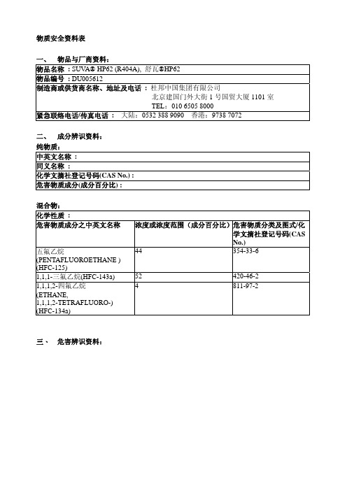
一、 物品与厂商资料:
物品名称 : SUVA® HP62 (R404A), 舒瓦®HP62 物品编号 : DU005612 制造商或供货商名称、地址及电话 : 杜邦中国集团有限公司
北京建国门外大街 1 号国贸大厦 1101 室 TEL:010 6505 8000 紧急联络电话/传真电话 : 大陆:0532 388 9090 香港:9738 7072
- 眼睛接触 : 1. 立即用大量的水冲洗眼睛至少 15 分钟。2. 送医。 - 食入 : 1. 不太可能食入,但若不慎食入时,送医。 最重要症状及危害效应 : 吸入导致心律不齐、失去意识、或死亡。蒸气会减少呼吸时获氧 量;接触会造成冻伤;过量吸入引起晕眩、虚弱感、头痛、困惑、动作不协调、失去意识、 脉搏不规则、心悸、或血液循环不良。 对急救人员之防护 : - 对医师之提示 :因为有扰乱心律的可能,Catecholamine 药物如肾上腺素(epinephrine),以及 其它具有类似效应的成份,仅能在急需紧急维生处置时特别小心地使用。
八、 暴露预防措施:
工程控制 : 1. 避免吸入蒸气;避免眼睛和皮肤接触到液体。2.使用足够的通风系统以使雇 员所处的环境低于暴露界限。3. 当大量释出时必须局部排气。4. 在低洼或密闭地区必须使 用机械式通风装置。5. 使用焊枪或其它引火源前,或是雇员身处于密封空间时,有必要监 测制冷剂的浓度以确定工作地区的蒸气浓度。 控制参数:
成都新为诚科技有限公司微型泵两用调节阀F2A系列产品说明书

微型泵两用调节阀F2A系列产品说明书(Ver.2021.9.1)版权所有©成都新为诚科技有限公司2020。
保留一切权利。
非经本公司书面许可,任何单位和个人不得擅自摘抄、复制本文档内容的部分或全部,并不得以任何形式传播。
商标声明商标为成都新为诚科技有限公司的商标。
本文档提及的其他所有商标或注册商标,由各自的所有人拥有。
注意您购买的产品、服务或特性等应受成都新为诚科技有限公司相关合同和条款的约束,本文档中描述的全部或部分产品、服务或特性可能未包含在您的购买或使用范围之内。
除非合同另有约定,成都新为诚科技有限公司对本文档内容不做任何明示或默示的声明或保证。
由于产品版本升级或其他原因,本文档内容会不定期进行更新。
除非另有约定,本文档仅作为使用指导,本文档中的所有陈述、信息和建议不构成任何明示或暗示的担保。
成都新为诚科技有限公司地址:成都市武侯区武侯大道顺江段77号汇点广场2座905-906邮编:610045网址:电话:************、66165538手机(微信同号):153****8198、133****9186天猫旗舰店:https:///微信公众号:前言摘要本文为微型泵两用调节阀F2A系列产品相关说明,用于指导相关技术人员了解该产品特性。
读者对象本文档适用于产品使用人员和相关技术人员。
您非常了解您的产品,并对所需微型泵的相关参数、规格大小等信息有明确概念。
关键字技术参数、操作说明、安装说明版本记录目录1产品外观及特点 (3)1.1产品外观 (3)1.2产品特点 (4)2技术参数 (6)2.1关键参数 (6)2.2原理 (7)2.3禁忌 (7)3安装说明 (8)3.1安装方向性 (8)3.2安装方式 (10)3.3拆卸和更换直通管或三通管 (11)4调节示意图 (12)4.1微型阀如何调节流量连接方式 (12)4.2微型阀调负压正压时连接方式 (14)5接头尺寸图 (18)6注意事项 (20)7微型阀F2A不同用途时安装尺寸图 (21)7.1F2A-3B7外形尺寸(单位:mm) (21)7.2F2A-3B7外形尺寸(单位:mm) (22)7.3F2A-3B11外形尺寸(单位:mm) (23)7.4F2A-3B11外形尺寸(单位:mm) (24)7.5F2A-3B13外形尺寸(单位:mm) (25)7.6F2A-3B13外形尺寸(单位:mm) (26)1产品外观及特点1.1产品外观1.2产品特点1.新为诚两用微型针型阀F2A系列,以品质气动元件厂家SMC阀芯为核心部件,搭配精密机加工直通接头或三通接头,与微型泵配合,既可以做微型流量阀调节流量,又可以做微型调压阀,调节负压、正压;2.新为诚微型针型阀F2A系列——“接头全能”;既可以接软管:接头采用2级或3级宝塔气嘴,兼容多种内径软管,内径3-6mm或5-10mm,弹性较好的软管都可以直接使用;又可以接Rc1/8螺纹硬管或外径8mm快插管;总有一款适合您!3.F2A-3B13微型针型阀,较独特的接口设计(配备Rc1/8内螺纹,可直接接外螺纹硬管!而行业微型针型阀多数配备得是接软管的宝塔接头),还可定做PC6/PC8的不锈钢快换接头,连接常用的外径6/8mm的快插管,迅速搭配气路。
天津曙光敬业 40 16 进化版电源箱 说明书
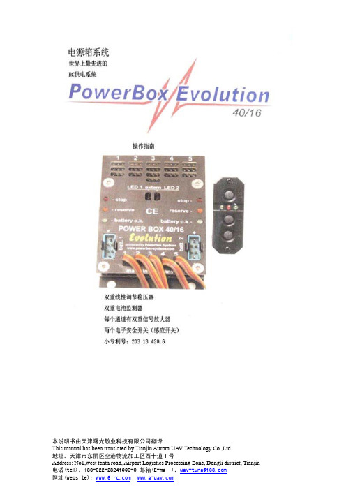
本说明书由天津曙光敬业科技有限公司翻译This manual has been translated by Tianjin Aurora UA V Technology Co.,Ltd.尊敬的用户:欢迎购买本公司的进化版电源箱 40/16。
将此先进的备用电池系统安装在您的飞机模型上可以使两个电池耦合(备用电池),并能长期监测两个电池的电压(镍镉电池、镍氢电池或锂电池)。
它可以储存电池电压曲线的最小值,并能在每次飞行后调出。
此备用电池为5个接收机的每个通道都配有集成双重舵机信号放大器,使其可以将多个舵机(最多4个)直接连接到一个输入端。
此备用电池为接收机和舵机提供5.9V稳定电压(线性稳压)。
尽管此设备易于操作,但是如果想要发挥其全部性能仍需对其深入了解。
第一次使用此供电系统时请认真通读此使用说明;这可使您快速熟悉此设备。
希望进化版电源箱 40/16给您带来快乐和成功。
目录1.电源箱系统备用电池的发展史 (2)2.产品说明 (2)3.PowerBox组件电路图 (5)4.特性 (5)5.接口和控制器 (5)6.安全操作此设备的说明 (6)7.感应开关 (7)8.维修 (10)本说明书由天津曙光敬业科技有限公司翻译This manual has been translated by Tianjin Aurora UA V Technology Co.,Ltd.1.电源箱系统稳压备用电池的发展史TOC 2002,拉斯韦加斯:这是第一个研发模型稳压供电系统的城市。
2002年10月,Sebastiano. Silverstri在拉斯韦加斯参加了TOC(冠军赛)比赛;他是第一个将接收供电系统安装在模型中的TOC参赛者。
此系统就是本公司研制成功的专业版电源箱40/24。
它是一个完整的舵机/接收机管理系统,带有“远程访问”通道(远程>到接收机的距离)、信号放大器和电压监测器等元件。
当时,欧洲的所有顶尖飞行员还在使用四芯或五芯镍镉电池或比较先进的镍氢电池飞行模型,而在美国,由著名电池生产商Duralite制造的锂电池已被顶尖飞行员广泛使用。
ISA3系列说明书

■关于操作者
①本使用说明书是面向对使用气动元件的设备·装置进行的组装·操作·维修保养具有足够知识和经 验的人员。 组装·操作·维修保养的实施,也仅限于此类人员。
②请在充分阅读本使用说明书并理解其内容基础上实施组装·操作·维修保养。
功能设定
37
功能选择模式 ··············· 37
出厂时的设定状态 ············· 37
键盘锁定(设定密码)
49
维护
50
故障一览表
51
错误显示 ················· 52
供给压力与显示的关系 ··········· 52
-1-
No.PS※※-OMR0001CN-D
■产品个别注意事项
警告
关于产品
・本产品不是防爆构造。 ・请不要使用含有化学药品、含有机溶剂的合成油、盐分、腐蚀性气体等流体。
会造成破损或故障、误动作。
・输入数据的写入次数为 100 万次。
关于设计
・请将主体安装到高于检测喷嘴的位置上。
如果产品主体的安装位置低于检测喷嘴,可能会有水或切削油等从检测喷嘴逆流到产品主体,造成误动作或故障。
※1) ISO 4414: Pneumatic fluid power -- General rules relating to systems ISO 4413: Hydraulic fluid power -- General rules relating to systems IEC 60204-1: Safety of machinery -- Electrical equipment of machines (Part 1: General requirements) ISO 10218-1992: Manipulating industrial robots-Safety JIS B 8370: 空气压系统通则 JIS B 8361: 油压系统通则 JIS B 9960-1: 机械类的安全性、机械的电气装置(第 1 部: 一般要求事项) JIS B 8433-1993: 产业用操作机器人-安全性等
SPEC00364 钢制抗冻双站泉水字型缸说明书

WATER INLET & DRAIN OUTLET Inlet: 1/4” O.D. TubingOutlet: 1-1/2” tube outlet for 1-1/2” slip joint connectionACCESS PANELSHeavy-gauge steel with vandal-resistant screws. Provides access for easy hook-up of all plumbing connections.PET FOUNTAINActuated by upper pushbutton. Slow drainage feature for easy drinking.NOTE: Pet Fountain will not be freeze-resistant.SUGGESTED SPECIFICATIONSUnit shall include powder-coated finish with vandal-resistant pushbutton actuation, vandal-resistant bubblers with integral hood guard, and contour-formed rounded basins to reduce splash and prevent standing water. Bottle Filler shall include a laminar flow for minimal splash and provide 1 gallon per minute fill rate. Fountain shall comply with ANSI 117:1 and ADA for visual and motion disabilities. The manufacturer shall certify the unit to meet the requirements of NSF/ANSI 61, and the Safe Drinking Water Act.Outdoor TubularModelLK4420BF1LDBFRK*ModelLK4420BF1UDBFRK*Beige Black BlueBrownEvergreen GrayOrange Purple Terracotta Red White YellowN o wA v a i l a b l e i n 12C o l o r s !Each 4420 FR consists of 2 cartons of the following:• FountainModelBottle Filler PlacementColor OptionADA CompliantNSF/ANSI 61CertifiedLK4420BF1UDBFRK*Upper (Refer to Finish Color Options)••LK4420BF1LDBFRK*Lower(Refer to Finish Color Options)••* Select color option to complete model number. Example: LK4420BF1UDBFRK EVGThis specification describes an Elkay product with design, quality and functional FINISH COLOR OPTIONS – Choose color option to complete your model number, add as suffix example: LK4420BF1UDBFRK EVG Matte finish: Evergreen = EVG Gloss finish: Beige = BGE Gray = GRYTerracotta = TER Black = BLK Orange = ORN White = WHT Blue = BLU Purple = PUR Yellow = YLWBrown = BRNRed = REDOPTIONS• Hose Bib (Locking) - LK4471LHB * (Choose color option to complete your model number)• Hose Bib (Non-Locking) - LK4470NLHB* (Choose coloroption to complete your model number)• Direct Bury Kit - 97890CA = ACCESS PANEL (8” x 10”)MODEL LK4420BF1UDBFRK Outdoor Tubular Bottle Filling StationOPERATING PRESSURES:Supply water 20 – 105 psi maximumMOUNTING INSTRUCTIONS and PLUMBING INSTRUCTIONSSite and drainage excavation is required for fountain installation. Refer to owner’s manual for site preparation details. Provide solid, well-drained surface to mount pedestal fountain (concrete pad recommended) with adequate support (300 lb. load minimum). (8) 3/8” minimum fasteners (not included) should be attached securely to mounting surface in order to secure fountain, (Refer to rough-in diagram), and be sure to allow an opening for the freeze-resistant valve in the ground as shown in the installation instructions that accompany the fountain. (Refer to page 4 for freeze resistant valve installation). NOTE: Pet Fountain will not be freeze resistant. Refer to local codes for any additional requirements.Locate and install plumbing through ground as required. Assemble fountain to prepared site and mounting pad.NOTE: Fountain is not furnished with service valve.Position pedestal over plumbing and secure base to fasteners. Remove access panels and connect supply and water lines. Turn on water supply and check for leaks. Refer to owner’s manual for detailed instructions.Reassemble access panels to pedestal. Trap and service stop not included.REFER TO PAGE 4 FORFREEZE RESISTANT VALVE INSTALLATIONNOTE: PET FOUNTAIN WILL NOT BEFREEZE RESISTANTFRONT & SIDE VIEWSMODEL LK4420BF1LDBFRK Outdoor TubularBottle Filling Station OPERATING PRESSURES: Supply water 20 – 105 psi maximumMOUNTING INSTRUCTIONS andPLUMBING INSTRUCTIONSSite and drainage excavation is required for fountain installation. Referto owner’s manual for site preparation details. Provide solid, well-drainedsurface to mount pedestal fountain (concrete pad recommended) withadequate support (300 lb. load minimum). (8) 3/8” minimum fasteners(not included) should be attached securely to mounting surface in orderto secure fountain, (Refer to rough-in diagram), and be sure to allowan opening for the freeze-resistant valve in the ground as shown in theinstallation instructions that accompany the fountain. (Refer to page 4 forfreeze resistant valve installation). NOTE: Pet Fountain will not be freezeresistant. Refer to local codes for any additional requirements.Locate and install plumbing through ground as required. Assemblefountain to prepared site and mounting pad.NOTE: Fountain is not furnished with service valve.Position pedestal over plumbing and secure base to fasteners. Removeaccess panels and connect supply and water lines. Turn on water supplyand check for leaks. Refer to owner’s manual for detailed instructions.Reassemble access panels to pedestal.Trap and service stop not included.A = ACCESS PANEL (8” x 10”)MODEL LK4420BF1UDBFRK Outdoor Tubular Bottle Filling StationOPERATING PRESSURES:Supply water 20 – 105 psi maximumMOUNTING INSTRUCTIONS and PLUMBING INSTRUCTIONSSite and drainage excavation is required for fountain installation. Refer to owner’s manual for site preparation details. Provide solid, well-drained surface to mount pedestal fountain (concrete pad recommended) with adequate support (300 lb. load minimum). (8) 3/8” minimum fasteners (not included) should be attached securely to mounting surface in order to secure fountain, (Refer to rough-in diagram), and be sure to allow an opening for the freeze-resistant valve in the ground as shown in the installation instructions that accompany the fountain. (Refer to page 4 for freeze resistant valve installation). NOTE: Pet Fountain will not be freeze resistant. Refer to local codes for any additional requirements.Locate and install plumbing through ground as required. Assemble fountain to prepared site and mounting pad.NOTE: Fountain is not furnished with service valve.Position pedestal over plumbing and secure base to fasteners. Remove access panels and connect supply and water lines. Turn on water supply and check for leaks. Refer to owner’s manual for detailed instructions.NOTE: PET FOUNTAIN WILL NOT BEFREEZE RESISTANTEndura II™ Outdoor Tubular Bottle Filling StationMODEL LK4420BF1LDBFRKMOUNTING INSTRUCTIONS and PLUMBING INSTRUCTIONSSite and drainage excavation is required for fountain installation. Refer to owner’s manual for site preparation details. Provide solid, well-drained surface to mount pedestal fountain (concrete pad recommended) with adequate support (300 lb. load minimum). (8) 3/8” minimum fasteners (not included) should be attached securely to mounting surface in order to secure fountain, (Refer to rough-in diagram), and be sure to allow an opening for the freeze-resistant valve in the ground as shown in the installation instructions that accompany the fountain. (Refer to page 4 for freeze resistant valve installation). NOTE: Pet Fountain will not be freeze resistant. Refer to local codes for any additional requirements.Locate and install plumbing through ground as required. Assemble fountain to prepared site and mounting pad.NOTE: Fountain is not furnished with service valve.Position pedestal over plumbing and secure base to fasteners. Remove access panels and connect supply and water lines. Turn on water supply and check for leaks. Refer to owner’s manual for detailed instructions.Reassemble access panels to pedestal. Trap and service stop not included.OPERATING PRESSURES:Supply water 20 – 105 psi maximumNOTE: PET FOUNTAIN WILL NOT BEFREEZE RESISTANTFRONT & SIDE VIEWS。
