Revit MEP教程
REVIT MEP软件教程 1 快速入门(25页)

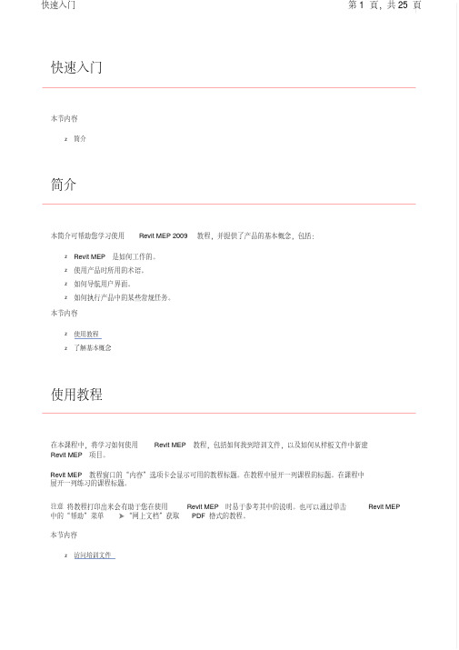
快速入门本节内容z简介简介本简介可帮助您学习使用 Revit MEP 2009 教程,并提供了产品的基本概念,包括:z Revit MEP 是如何工作的。
z使用产品时所用的术语。
z如何导航用户界面。
z如何执行产品中的某些常规任务。
本节内容z使用教程z了解基本概念使用教程在本课程中,将学习如何使用 Revit MEP 教程,包括如何找到培训文件,以及如何从样板文件中新建 Revit MEP 项目。
Revit MEP 教程窗口的“内容”选项卡会显示可用的教程标题。
在教程中展开一列课程的标题。
在课程中展开一列练习的课程标题。
注意将教程打印出来会有助于您在使用 Revit MEP 时易于参考其中的说明。
也可以通过单击 Revit MEP 中的“帮助”菜单 “网上文档”获取 PDF 格式的教程。
本节内容z访问培训文件访问培训文件培训文件是专门为教程的使用而创建的 Revit MEP 项目、样板和族。
在本练习中,将学习如何找到培训文件,以及如何打开并保存培训文件。
如何找到培训文件的位置?默认情况下,培训文件位于“C:\Documents and Settings\All Users\Application Data\Autodesk\RME 2009\Training"。
在“Training"文件夹中,培训文件被分为 3 个文件夹:z Common:讲授概念时经常用到的一般文件。
这些文件与英制或公制单位无关。
常规文件的名称中含有前缀 c_。
z Imperial:指为使用英制单位的用户准备的文件。
英制文件的名称中含有前缀 i_。
z Metric:指为使用公制单位的用户准备的文件。
公制文件的名称中含有前缀 m_。
注意根据安装情况的不同,培训文件夹可能位于不同的位置。
联系 CAD 管理员可获得详细信息。
重要信息可在培训文件位置找到并访问教程中所使用的内容(如样板和族)。
尽管此内容可能安装在您计算机的其他位置,但本教程中使用的所有内容都包含在培训文件位置中,以确保所有读者都能访问正确的文件。
Revit+MEP+基本概述教程

R e v i t M E P基本概述教程本教程将提供有关Revit MEP 学习入门的信息,主要内容包括:概况介绍在教程中设计的建筑信息模型的基本概念和相关术语以及如何与其它相关专业开展协同设计的操作流程。
在这些教程中,用户将学习如何在Revit MEP 中创建并设计建筑信息模型(BIM)。
同时也将学习与Revit Architecture 和Revit Structure 两款兄弟产品的链接操作与协同设计。
教程的组织方式:本教程是遵循典型的机械、电气和卫浴工程的工作流。
用户将在后续的详细教程完成以下设计培训:•导入二维(DWG) 或三维(RVT) 格式的建筑楼层平面。
•添加基本MEP 图元,如风管、装置和管道。
•添加更详细的建模图元,如机械设备、配电盘和卫浴装置。
•分析系统并优化MEP 图元。
•创建明细表、视图和图纸,以创建项目施工图。
•创建详图视图、注释和标记。
教程练习的设计遵循基本和简明的原则。
用户不必设计整个系统,而只需设计足以了解本产品中各种工具和选项的使用方法的部分系统即可。
例如,添加管网时,只需在建筑的一个翼楼中绘制风管。
在打开有些培训文件时,用户会注意到文件中包含之前在练习中并未特别添加的MEP 图元。
例如,为提供更丰富且更完善的设计,在后续培训文件中并入了诸如其他管网和设备等图元。
这些图元强化了用户将完成的练习。
★了解基本概念在本课程中,将学习Revit MEP 是什么,以及如何从其参数化修改引擎功能中受益。
先从Revit MEP 所依据的基本概念入手。
用户将学习术语、图元层次结构,以及如何在产品中执行某些常见任务。
★了解概念什么是Autodesk Revit MEP?用于建筑信息模型的Revit MEP 平台是建筑设计和文档系统,它支持建筑项目所需的设计、图纸以及明细表。
建筑信息模型(BIM) 提供了用户需要的有关项目设计、范围、数量和阶段等信息。
在Revit MEP 模型中,所有的图纸、二维视图和三维视图以及明细表都是同一个基本建筑模型数据库的信息表现形式。
《RevitMEP教程》课件

电气系统
掌握在RevitMEP中设计和 布线电气系统的技巧,包 括照明、插座和配电系统。
管道系统
了解在RevitMEP中建模和 优化管道系统,包括给水、 排水和消防系统。
模型构建技巧
分享一些实用的建模技巧,帮助您提高建模效率和质量,包括族编辑、参数 化建模和模型协作。
பைடு நூலகம்
实例演示
1
示例项目1
通过一个实际建筑项目的演示,展示RevitMEP在实践中的应用和优势。
界面功能
详细解析RevitMEP的界面布局和各个功能区域,帮助您快速上手并提高工作 效率。
系统设置
介绍如何进行RevitMEP的系统设置,包括单位设置、协作设置等,确保项目 文件的准确性和一致性。
三大模块详解
机械系统
学习如何在RevitMEP中创 建和编辑机械系统,包括 空调、通风和制冷系统。
2
示例项目2
进一步深入了解RevitMEP的高级功能和复杂项目的应用示例。
3
实用技巧
分享一些实用的技巧和技术,帮助您更好地利用RevitMEP完成各种工作任务。
《RevitMEP教程》PPT课 件
通过本课件,您将深入了解RevitMEP的各个方面,掌握软件的使用技巧和模 型构建方法,并通过实例演示加深理解。
RevitMEP教程概述
本节将介绍RevitMEP教程的内容和目的,以及学习本教程的前提要求。
软件介绍
了解RevitMEP的基本信息,包括功能和适用领域,以及它与其他建模软件的比较优势。
REVIT MEP软件教程 3-2 电气系统(86页)
(Building Information Modeling ,建筑信息建模)的强大功能。
这就是未来的系统设计 - Revit MEP 2009。
在本教程中,将学习如何使用建筑项目的链接建筑模型创建电气系统。
该建筑物中有多个空间,您将在其中设计照明和电力系统。
第一课中提供了一些练习,通过这些练习可以为在下节课中要设计的各种系统类型准备项目。
注意本教程中使用的建筑模型位于“Architectural "文件夹中。
您应该维护指向建筑模型的相对路径。
不过,如果链接丢失,则可单击“文件”菜单 “管理链接”重新载入链接模型。
在“管理链接”对话框中的“Revit "选项卡上,单击“重新载入来自”,定位到“Training Files "“Metric "“Electrical "“Metric_Arch_Model ",然后选择“m Office Building.rvt "。
用来完成这些练习的数据集位于“Training Files "目录中。
可以通过搜索“Training Files "“Metric "目录来确认是否已下载这些数据集。
如果教程数据集不存在,请转到 /revitmep-documentation 并进行下载。
注意本教程中的所有练习需要按顺序完成,只有完成前一练习,才能继续下一练习。
在完成每个练习后,可以选择保存工作。
但是,强烈建议始终通过打开 Autodesk 提供的数据集开始练习。
此数据集包括前面的练习中的工作,并可确保不间断地完成培训课程。
本节内容z 规划电气系统 z设计电气系统在 Revit MEP 中设计系统的最常用方法是在链接的建筑模型中工作。
在本教程中,将使用已链接到建筑模型的项目文件,其中该模型的所有区域中均已放置了“空间”构件。
要了解更多关于链接和准备建筑模型的信息,请参见“机械系统”教程中的“规划机械系统”。
在本课程中,将指定电气设置,载入包含构成电气系统的电气构件的族,并创建设计项目的电气系统时所需的明细表。
Revit MEP 2011用户指南说明书

Revit MEP 2011 User's GuideApril 2010©2010 Autodesk, Inc. All Rights Reserved. Except as otherwise permitted by Autodesk, Inc., this publication, or parts thereof, may not be reproduced in any form, by any method, for any purpose.Certain materials included in this publication are reprinted with the permission of the copyright holder.DisclaimerTHIS PUBLICATION AND THE INFORMATION CONTAINED HEREIN IS MADE AVAILABLE BY AUTODESK, INC. "AS IS." AUTODESK, INC. DISCLAIMS ALL WARRANTIES, EITHER EXPRESS OR IMPLIED, INCLUDING BUT NOT LIMITED TO ANY IMPLIED WARRANTIES OF MERCHANTABILITY OR FITNESS FOR A PARTICULAR PURPOSE REGARDING THESE MATERIALS.TrademarksThe following are registered trademarks or trademarks of Autodesk, Inc., and/or its subsidiaries and/or affiliates in the USA and other countries: 3DEC (design/logo), 3December, , 3ds Max, Algor, Alias, Alias (swirl design/logo), AliasStudio, Alias|Wavefront (design/logo), ATC, AUGI, AutoCAD, AutoCAD Learning Assistance, AutoCAD LT, AutoCAD Simulator, AutoCAD SQL Extension, AutoCAD SQL Interface, Autodesk, Autodesk Envision, Autodesk Intent, Autodesk Inventor, Autodesk Map, Autodesk MapGuide, Autodesk Streamline, AutoLISP, AutoSnap, AutoSketch, AutoTrack, Backburner, Backdraft, Built with ObjectARX (logo), Burn, Buzzsaw, CAiCE, Civil 3D, Cleaner, Cleaner Central, ClearScale, Colour Warper, Combustion, Communication Specification, Constructware, Content Explorer, Dancing Baby (image), DesignCenter, Design Doctor, Designer's Toolkit, DesignKids, DesignProf, DesignServer, DesignStudio, Design Web Format, Discreet, DWF, DWG, DWG (logo), DWG Extreme, DWG TrueConvert, DWG TrueView, DXF, Ecotect, Exposure, Extending the Design Team, Face Robot, FBX, Fempro, Fire, Flame, Flare, Flint, FMDesktop, Freewheel, GDX Driver, Green Building Studio, Heads-up Design, Heidi, HumanIK, IDEA Server, i-drop, ImageModeler, iMOUT, Incinerator, Inferno, Inventor, Inventor LT, Kaydara, Kaydara (design/logo), Kynapse, Kynogon, LandXplorer, Lustre, MatchMover, Maya, Mechanical Desktop, Moldflow, Moonbox, MotionBuilder, Movimento, MPA, MPA (design/logo), Moldflow Plastics Advisers, MPI, Moldflow Plastics Insight, MPX, MPX (design/logo), Moldflow Plastics Xpert, Mudbox, Multi-Master Editing, Navisworks, ObjectARX, ObjectDBX, Open Reality, Opticore, Opticore Opus, Pipeplus, PolarSnap, PortfolioWall, Powered with Autodesk Technology, Productstream, ProjectPoint, ProMaterials, RasterDWG, RealDWG, Real-time Roto, Recognize, Render Queue, Retimer,Reveal, Revit, Showcase, ShowMotion, SketchBook, Smoke, Softimage, Softimage|XSI (design/logo), Sparks, SteeringWheels, Stitcher, Stone, StudioTools, ToolClip, Topobase, Toxik, TrustedDWG, ViewCube, Visual, Visual LISP, Volo, Vtour, Wire, Wiretap, WiretapCentral, XSI, and XSI (design/logo).ContentsChapter 1What’s New? . . . . . . . . . . . . . . . . . . . . . . . . . . . . . . . . . . . . . . . . . . . 1 New in Revit MEP 2011 . . . . . . . . . . . . . . . . . . . . . . . . . . . . . . . . . . . . . . . . . . . 1Introduction to Revit . . . . . . . . . . . . . . . . . . . . . . . . . . . . . . . . . . 9Chapter 2Building Information Modeling . . . . . . . . . . . . . . . . . . . . . . . . . . . . . . . . 11 What Is Revit MEP? . . . . . . . . . . . . . . . . . . . . . . . . . . . . . . . . . . . . . . . . . . . . 11What Is Meant by Parametric? . . . . . . . . . . . . . . . . . . . . . . . . . . . . . . . . . . . . . . . 11How Does Revit MEP Keep Things Updated? . . . . . . . . . . . . . . . . . . . . . . . . . . . . . . . 12Understanding Revit Terms . . . . . . . . . . . . . . . . . . . . . . . . . . . . . . . . . . . . . . . . 12Element Behavior in a Parametric Modeler . . . . . . . . . . . . . . . . . . . . . . . . . . . . . . . . 14Element Properties . . . . . . . . . . . . . . . . . . . . . . . . . . . . . . . . . . . . . . . . . . . . . 15Chapter 3Licensing . . . . . . . . . . . . . . . . . . . . . . . . . . . . . . . . . . . . . . . . . . . . 17 Licensing Overview . . . . . . . . . . . . . . . . . . . . . . . . . . . . . . . . . . . . . . . . . . . . 17Standalone Licensing . . . . . . . . . . . . . . . . . . . . . . . . . . . . . . . . . . . . . . . . . . . 17Licensing Extension . . . . . . . . . . . . . . . . . . . . . . . . . . . . . . . . . . . . . . . . . . . . 18License Transferring . . . . . . . . . . . . . . . . . . . . . . . . . . . . . . . . . . . . . . . . . . . . 18License Borrowing . . . . . . . . . . . . . . . . . . . . . . . . . . . . . . . . . . . . . . . . . . . . . 18Chapter 4User Interface . . . . . . . . . . . . . . . . . . . . . . . . . . . . . . . . . . . . . . . . . . 21 Ribbon . . . . . . . . . . . . . . . . . . . . . . . . . . . . . . . . . . . . . . . . . . . . . . . . . . . 21 Customizing the Ribbon . . . . . . . . . . . . . . . . . . . . . . . . . . . . . . . . . . . . . . . 22 Application Menu . . . . . . . . . . . . . . . . . . . . . . . . . . . . . . . . . . . . . . . . . . . . . 24Quick Access Toolbar . . . . . . . . . . . . . . . . . . . . . . . . . . . . . . . . . . . . . . . . . . . 25Tooltips . . . . . . . . . . . . . . . . . . . . . . . . . . . . . . . . . . . . . . . . . . . . . . . . . . . 26Keytips . . . . . . . . . . . . . . . . . . . . . . . . . . . . . . . . . . . . . . . . . . . . . . . . . . . 27Project Browser . . . . . . . . . . . . . . . . . . . . . . . . . . . . . . . . . . . . . . . . . . . . . . . 28 Using the Project Browser . . . . . . . . . . . . . . . . . . . . . . . . . . . . . . . . . . . . . . 28 Drawing Area . . . . . . . . . . . . . . . . . . . . . . . . . . . . . . . . . . . . . . . . . . . . . . . . 32iiiStatus Bar . . . . . . . . . . . . . . . . . . . . . . . . . . . . . . . . . . . . . . . . . . . . . . . . . . 33Options Bar . . . . . . . . . . . . . . . . . . . . . . . . . . . . . . . . . . . . . . . . . . . . . . . . 34Properties Palette . . . . . . . . . . . . . . . . . . . . . . . . . . . . . . . . . . . . . . . . . . . . . . 34 Modifying Instance Properties . . . . . . . . . . . . . . . . . . . . . . . . . . . . . . . . . . . . 36Modifying Type Properties . . . . . . . . . . . . . . . . . . . . . . . . . . . . . . . . . . . . . . 37Creating a New Family Type in a Project . . . . . . . . . . . . . . . . . . . . . . . . . . . . . . 38Previewing Family Types . . . . . . . . . . . . . . . . . . . . . . . . . . . . . . . . . . . . . . 38 View Control Bar . . . . . . . . . . . . . . . . . . . . . . . . . . . . . . . . . . . . . . . . . . . . . . 39Recent Files . . . . . . . . . . . . . . . . . . . . . . . . . . . . . . . . . . . . . . . . . . . . . . . . . 40InfoCenter . . . . . . . . . . . . . . . . . . . . . . . . . . . . . . . . . . . . . . . . . . . . . . . . . 40 Overview of InfoCenter . . . . . . . . . . . . . . . . . . . . . . . . . . . . . . . . . . . . . . . 40Search For Information . . . . . . . . . . . . . . . . . . . . . . . . . . . . . . . . . . . . . . . 41Receive Product Updates and Announcements . . . . . . . . . . . . . . . . . . . . . . . . . . . 42Save and Access Favorite Topics . . . . . . . . . . . . . . . . . . . . . . . . . . . . . . . . . . . 43Specify InfoCenter Settings . . . . . . . . . . . . . . . . . . . . . . . . . . . . . . . . . . . . . 44Search Topics in Help . . . . . . . . . . . . . . . . . . . . . . . . . . . . . . . . . . . . . . . . 47 Autodesk® Seek . . . . . . . . . . . . . . . . . . . . . . . . . . . . . . . . . . . . . . . . . . . . . . 47 Searching for Content with Autodesk Seek . . . . . . . . . . . . . . . . . . . . . . . . . . . . . 49 Online Help . . . . . . . . . . . . . . . . . . . . . . . . . . . . . . . . . . . . . . . . . . . . . . . . 52Start a Project . . . . . . . . . . . . . . . . . . . . . . . . . . . . . . . . . . . . . 53Chapter 5C reating a Project . . . . . . . . . . . . . . . . . . . . . . . . . . . . . . . . . . . . . . . 55 Creating a Project Using Default Settings . . . . . . . . . . . . . . . . . . . . . . . . . . . . . . . . . 55Creating a Project Using a Template . . . . . . . . . . . . . . . . . . . . . . . . . . . . . . . . . . . . 55Before You Begin a Project . . . . . . . . . . . . . . . . . . . . . . . . . . . . . . . . . . . . . . . . . 56Chapter 6Using Information from Other Sources . . . . . . . . . . . . . . . . . . . . . . . . . . . . 57 Import/Link Overview . . . . . . . . . . . . . . . . . . . . . . . . . . . . . . . . . . . . . . . . . . . 57 Suitability of Imported Geometry . . . . . . . . . . . . . . . . . . . . . . . . . . . . . . . . . . 57Implications of Importing vs. Linking for Xrefs . . . . . . . . . . . . . . . . . . . . . . . . . . 58 Importing or Linking CAD Formats . . . . . . . . . . . . . . . . . . . . . . . . . . . . . . . . . . . . 58 Importing or Linking CAD Files Using the Import CAD and Link CAD Tools . . . . . . . . . . . 59Importing CAD Files Using i-drop . . . . . . . . . . . . . . . . . . . . . . . . . . . . . . . . . . 59Importing Files from SketchUp . . . . . . . . . . . . . . . . . . . . . . . . . . . . . . . . . . . 60Importing ACIS Objects . . . . . . . . . . . . . . . . . . . . . . . . . . . . . . . . . . . . . . . 62Import and Link Options for CAD Formats and Revit Models . . . . . . . . . . . . . . . . . . . 63Setting Scaling for Imported DWG or DXF Files . . . . . . . . . . . . . . . . . . . . . . . . . . 65Setting Line Weights for Imported DWG or DXF Files . . . . . . . . . . . . . . . . . . . . . . . 65Mapping AutoCAD SHX Fonts to TrueType Fonts . . . . . . . . . . . . . . . . . . . . . . . . . 65Setting Constraint Parameters for Imported Geometry . . . . . . . . . . . . . . . . . . . . . . . 66Moving a View-Specific Import to the Foreground or Background . . . . . . . . . . . . . . . . . 66 Importing Images . . . . . . . . . . . . . . . . . . . . . . . . . . . . . . . . . . . . . . . . . . . . . 66 Modifying Imported Images . . . . . . . . . . . . . . . . . . . . . . . . . . . . . . . . . . . . . 67Deleting Raster Images . . . . . . . . . . . . . . . . . . . . . . . . . . . . . . . . . . . . . . . . 67 Importing Building Components . . . . . . . . . . . . . . . . . . . . . . . . . . . . . . . . . . . . . 68 Building Component ADSK Files . . . . . . . . . . . . . . . . . . . . . . . . . . . . . . . . . . 68Working with Building Components . . . . . . . . . . . . . . . . . . . . . . . . . . . . . . . . 68Tips for Working with Building Components . . . . . . . . . . . . . . . . . . . . . . . . . . . . 69Building Component Workflow . . . . . . . . . . . . . . . . . . . . . . . . . . . . . . . . . . . 69 Opening Industry Foundation Class (IFC) Files . . . . . . . . . . . . . . . . . . . . . . . . . . . . . . 70 Selecting a Template for IFC Files . . . . . . . . . . . . . . . . . . . . . . . . . . . . . . . . . . 71Loading an IFC Class Mapping File . . . . . . . . . . . . . . . . . . . . . . . . . . . . . . . . . 71Overriding Categories and Subcategories for IFC Objects . . . . . . . . . . . . . . . . . . . . . . 71 Linking AutoCAD Files to a Revit Project . . . . . . . . . . . . . . . . . . . . . . . . . . . . . . . . . 71 How Linking to AutoCAD Files Works . . . . . . . . . . . . . . . . . . . . . . . . . . . . . . . 72Linking to an AutoCAD File . . . . . . . . . . . . . . . . . . . . . . . . . . . . . . . . . . . . . 72 iv | ContentsLocation of the Linked File . . . . . . . . . . . . . . . . . . . . . . . . . . . . . . . . . . . . . 73 Linking DWF Markup Files . . . . . . . . . . . . . . . . . . . . . . . . . . . . . . . . . . . . . . . . 74 Modifying DWF Markups Created in Design Review . . . . . . . . . . . . . . . . . . . . . . . . 74 Exploding Imported Geometry . . . . . . . . . . . . . . . . . . . . . . . . . . . . . . . . . . . . . . 75Managing Layers in Linked and Imported Files . . . . . . . . . . . . . . . . . . . . . . . . . . . . . . 75 Querying Objects in Layers . . . . . . . . . . . . . . . . . . . . . . . . . . . . . . . . . . . . . 75Hiding and Deleting Layers . . . . . . . . . . . . . . . . . . . . . . . . . . . . . . . . . . . . . 76Changing the Graphic Display of Layers . . . . . . . . . . . . . . . . . . . . . . . . . . . . . . 78 Importing a Loads Analysis from a gbXML File . . . . . . . . . . . . . . . . . . . . . . . . . . . . . . 79Troubleshooting Problems with Linked Files . . . . . . . . . . . . . . . . . . . . . . . . . . . . . . . 80 Changes in the DWG File Are Not Reflected in the Revit Project . . . . . . . . . . . . . . . . . . 80Changes to the Layer Color and Line Style Do Not Display in the Revit Project . . . . . . . . . . 80Layers in the DWG File Do Not Display in the Revit Project . . . . . . . . . . . . . . . . . . . . 80File Operations (Open, Save, Synchronize) Are Blocked or Slow . . . . . . . . . . . . . . . . . . 81Chapter 7Opening Revit Files . . . . . . . . . . . . . . . . . . . . . . . . . . . . . . . . . . . . . . . 83 Opening a Revit Project File . . . . . . . . . . . . . . . . . . . . . . . . . . . . . . . . . . . . . . . . 83Opening Families and Training Files . . . . . . . . . . . . . . . . . . . . . . . . . . . . . . . . . . . 84Opening Files from the Conceptual Design Environment . . . . . . . . . . . . . . . . . . . . . . . . 84Opening Files from the Web Library . . . . . . . . . . . . . . . . . . . . . . . . . . . . . . . . . . . 84Opening Revit Files from Windows Explorer . . . . . . . . . . . . . . . . . . . . . . . . . . . . . . . 85Chapter 8Saving Revit Files . . . . . . . . . . . . . . . . . . . . . . . . . . . . . . . . . . . . . . . . 87 Saving a File with a Different Name or Location . . . . . . . . . . . . . . . . . . . . . . . . . . . . . 87Save Options . . . . . . . . . . . . . . . . . . . . . . . . . . . . . . . . . . . . . . . . . . . . . . . . 88Setting Save Reminders . . . . . . . . . . . . . . . . . . . . . . . . . . . . . . . . . . . . . . . . . . 88Backup and Journal Files . . . . . . . . . . . . . . . . . . . . . . . . . . . . . . . . . . . . . . . . . . 89 Specifying the Number of Backup Files . . . . . . . . . . . . . . . . . . . . . . . . . . . . . . . 89Backup Files for Network Saves . . . . . . . . . . . . . . . . . . . . . . . . . . . . . . . . . . . 89Journal Files . . . . . . . . . . . . . . . . . . . . . . . . . . . . . . . . . . . . . . . . . . . . . 90 Preliminary Design . . . . . . . . . . . . . . . . . . . . . . . . . . . . . . . . . . 91Chapter 9Levels and Grids . . . . . . . . . . . . . . . . . . . . . . . . . . . . . . . . . . . . . . . . 93 Levels . . . . . . . . . . . . . . . . . . . . . . . . . . . . . . . . . . . . . . . . . . . . . . . . . . . . 93 Adding Levels . . . . . . . . . . . . . . . . . . . . . . . . . . . . . . . . . . . . . . . . . . . . 94Modifying Levels . . . . . . . . . . . . . . . . . . . . . . . . . . . . . . . . . . . . . . . . . . . 95Level Properties . . . . . . . . . . . . . . . . . . . . . . . . . . . . . . . . . . . . . . . . . . . 96 Grids . . . . . . . . . . . . . . . . . . . . . . . . . . . . . . . . . . . . . . . . . . . . . . . . . . . . 98 Adding Grids . . . . . . . . . . . . . . . . . . . . . . . . . . . . . . . . . . . . . . . . . . . . . 99Modifying Grids . . . . . . . . . . . . . . . . . . . . . . . . . . . . . . . . . . . . . . . . . . . 99Grid Properties . . . . . . . . . . . . . . . . . . . . . . . . . . . . . . . . . . . . . . . . . . . 105Chapter 10Project Location and Orientation . . . . . . . . . . . . . . . . . . . . . . . . . . . . . . . 107 Specifying the Project Location . . . . . . . . . . . . . . . . . . . . . . . . . . . . . . . . . . . . . 107 Troubleshooting Location Dialog Issues . . . . . . . . . . . . . . . . . . . . . . . . . . . . . . 111 Rotating a View to True North . . . . . . . . . . . . . . . . . . . . . . . . . . . . . . . . . . . . . . 112Rotating Project North . . . . . . . . . . . . . . . . . . . . . . . . . . . . . . . . . . . . . . . . . . 113Chapter 11C onceptual Design Environment . . . . . . . . . . . . . . . . . . . . . . . . . . . . . . . 115 Conceptual Design Environment Overview . . . . . . . . . . . . . . . . . . . . . . . . . . . . . . . 116 Exploring Conceptual Designs . . . . . . . . . . . . . . . . . . . . . . . . . . . . . . . . . . . 116Early Conceptual Study Models . . . . . . . . . . . . . . . . . . . . . . . . . . . . . . . . . . 116Integrated Study Models . . . . . . . . . . . . . . . . . . . . . . . . . . . . . . . . . . . . . . 117Intelligent Sub-Components . . . . . . . . . . . . . . . . . . . . . . . . . . . . . . . . . . . . 117 Conceptual Design Environment Interface . . . . . . . . . . . . . . . . . . . . . . . . . . . . . . . 117Contents | vConceptual Massing Family Creation . . . . . . . . . . . . . . . . . . . . . . . . . . . . . . . 118Switching between Conceptual Design and Project Environments . . . . . . . . . . . . . . . . 118Template Files for the Conceptual Design Environment . . . . . . . . . . . . . . . . . . . . . 120 Drawing in the Conceptual Design Environment . . . . . . . . . . . . . . . . . . . . . . . . . . . . 121 Drawing Overview . . . . . . . . . . . . . . . . . . . . . . . . . . . . . . . . . . . . . . . . . 1213D Snapping . . . . . . . . . . . . . . . . . . . . . . . . . . . . . . . . . . . . . . . . . . . . 1213D Aligning . . . . . . . . . . . . . . . . . . . . . . . . . . . . . . . . . . . . . . . . . . . . . 122Conceptual Design Model Line Instance Properties . . . . . . . . . . . . . . . . . . . . . . . . 1243D Work Planes . . . . . . . . . . . . . . . . . . . . . . . . . . . . . . . . . . . . . . . . . . . 1253D Levels . . . . . . . . . . . . . . . . . . . . . . . . . . . . . . . . . . . . . . . . . . . . . . 1283D Reference Planes . . . . . . . . . . . . . . . . . . . . . . . . . . . . . . . . . . . . . . . . 131Reference Points . . . . . . . . . . . . . . . . . . . . . . . . . . . . . . . . . . . . . . . . . . 132 X-Ray Mode . . . . . . . . . . . . . . . . . . . . . . . . . . . . . . . . . . . . . . . . . . . . . . . . 143 Accessing X-Ray Mode . . . . . . . . . . . . . . . . . . . . . . . . . . . . . . . . . . . . . . . 143Display of Elements in X-Ray Mode . . . . . . . . . . . . . . . . . . . . . . . . . . . . . . . . 143Manipulating Forms in X-Ray Mode . . . . . . . . . . . . . . . . . . . . . . . . . . . . . . . . 144 Profiles . . . . . . . . . . . . . . . . . . . . . . . . . . . . . . . . . . . . . . . . . . . . . . . . . . 145 Locked Profiles . . . . . . . . . . . . . . . . . . . . . . . . . . . . . . . . . . . . . . . . . . . 145Locking and Unlocking Profiles . . . . . . . . . . . . . . . . . . . . . . . . . . . . . . . . . . 146 Forms . . . . . . . . . . . . . . . . . . . . . . . . . . . . . . . . . . . . . . . . . . . . . . . . . . . 147 Solid and Void Forms . . . . . . . . . . . . . . . . . . . . . . . . . . . . . . . . . . . . . . . . 147Creating Solid Forms . . . . . . . . . . . . . . . . . . . . . . . . . . . . . . . . . . . . . . . . 148Creating Void Forms . . . . . . . . . . . . . . . . . . . . . . . . . . . . . . . . . . . . . . . . 150Accessing Create Form Tool . . . . . . . . . . . . . . . . . . . . . . . . . . . . . . . . . . . . 150Unconstrained and Referenced-Based Forms . . . . . . . . . . . . . . . . . . . . . . . . . . . 151Selecting Forms . . . . . . . . . . . . . . . . . . . . . . . . . . . . . . . . . . . . . . . . . . . 152Form Types . . . . . . . . . . . . . . . . . . . . . . . . . . . . . . . . . . . . . . . . . . . . . 153Modifying Forms . . . . . . . . . . . . . . . . . . . . . . . . . . . . . . . . . . . . . . . . . . 160Rehosting Forms . . . . . . . . . . . . . . . . . . . . . . . . . . . . . . . . . . . . . . . . . . 164Dimensioning Forms . . . . . . . . . . . . . . . . . . . . . . . . . . . . . . . . . . . . . . . . 164Referencing Imported Geometry . . . . . . . . . . . . . . . . . . . . . . . . . . . . . . . . . . 166Conceptual Design Environment Model Instance Properties . . . . . . . . . . . . . . . . . . . 167Manipulating Forms . . . . . . . . . . . . . . . . . . . . . . . . . . . . . . . . . . . . . . . . 167Manipulating Joined Forms . . . . . . . . . . . . . . . . . . . . . . . . . . . . . . . . . . . . 168 Rationalizing Surfaces . . . . . . . . . . . . . . . . . . . . . . . . . . . . . . . . . . . . . . . . . . 170 Dividing a Surface with UV Grids . . . . . . . . . . . . . . . . . . . . . . . . . . . . . . . . . 170Understanding UV Grids . . . . . . . . . . . . . . . . . . . . . . . . . . . . . . . . . . . . . . 170Enabling and Disabling UV Grids . . . . . . . . . . . . . . . . . . . . . . . . . . . . . . . . . 171Modifying the Spacing of UV Grids on Divided Surfaces . . . . . . . . . . . . . . . . . . . . . 172Adjusting UV Grids with the Face Manager . . . . . . . . . . . . . . . . . . . . . . . . . . . . 172Dividing a Surface by Intersection . . . . . . . . . . . . . . . . . . . . . . . . . . . . . . . . . 176Patterning Surfaces . . . . . . . . . . . . . . . . . . . . . . . . . . . . . . . . . . . . . . . . . 177Editing the Patterned Surface . . . . . . . . . . . . . . . . . . . . . . . . . . . . . . . . . . . 180Pattern Component Families . . . . . . . . . . . . . . . . . . . . . . . . . . . . . . . . . . . . 181Surface Representation . . . . . . . . . . . . . . . . . . . . . . . . . . . . . . . . . . . . . . . 190Pattern Element Properties . . . . . . . . . . . . . . . . . . . . . . . . . . . . . . . . . . . . . 191 Conceptual Design Environment Glossary . . . . . . . . . . . . . . . . . . . . . . . . . . . . . . . 194Chapter 12Revit MEP Essentials . . . . . . . . . . . . . . . . . . . . . . . . . . . . . . . . . . . . . . 197 Connect Into . . . . . . . . . . . . . . . . . . . . . . . . . . . . . . . . . . . . . . . . . . . . . . . 197System Browser . . . . . . . . . . . . . . . . . . . . . . . . . . . . . . . . . . . . . . . . . . . . . . 197 Column Settings . . . . . . . . . . . . . . . . . . . . . . . . . . . . . . . . . . . . . . . . . . 198 Selecting Column Headings . . . . . . . . . . . . . . . . . . . . . . . . . . . . . . . . . 198 System Inspector . . . . . . . . . . . . . . . . . . . . . . . . . . . . . . . . . . . . . . . . . . . . . 199 Using the System Inspector . . . . . . . . . . . . . . . . . . . . . . . . . . . . . . . . . . . . 199 Spaces . . . . . . . . . . . . . . . . . . . . . . . . . . . . . . . . . . . . . . . . . . . . . . . . . . . 199 Place Spaces Automatically . . . . . . . . . . . . . . . . . . . . . . . . . . . . . . . . . . . . . 201Space Creation During Project Upgrade . . . . . . . . . . . . . . . . . . . . . . . . . . . . . . 201Volume Computations . . . . . . . . . . . . . . . . . . . . . . . . . . . . . . . . . . . . . . . 202 vi | ContentsPlacing Spaces . . . . . . . . . . . . . . . . . . . . . . . . . . . . . . . . . . . . . . . . . . . 203 Placing Spaces Up to the Level Above . . . . . . . . . . . . . . . . . . . . . . . . . . . . 204Placing Spaces up to the Ceiling . . . . . . . . . . . . . . . . . . . . . . . . . . . . . . . 206Placing Spaces for Plenums . . . . . . . . . . . . . . . . . . . . . . . . . . . . . . . . . 210Placing Spaces Up to the Roof . . . . . . . . . . . . . . . . . . . . . . . . . . . . . . . . 213Placing Spaces for Complex Vertical Areas . . . . . . . . . . . . . . . . . . . . . . . . . . 216Placing Spaces for Shafts and Chases . . . . . . . . . . . . . . . . . . . . . . . . . . . . 221Adding Space Tags . . . . . . . . . . . . . . . . . . . . . . . . . . . . . . . . . . . . . . 223 Accounting for the Volume of Cavities, Shafts, and Chases . . . . . . . . . . . . . . . . . . . . 224 Resolving the Volume of Cavities, Shafts, and Chases . . . . . . . . . . . . . . . . . . . 225 Modifying Spaces . . . . . . . . . . . . . . . . . . . . . . . . . . . . . . . . . . . . . . . . . . 227 Redefining the Vertical Extent of a Space . . . . . . . . . . . . . . . . . . . . . . . . . . 227Dividing Spaces . . . . . . . . . . . . . . . . . . . . . . . . . . . . . . . . . . . . . . . . 234Combining Spaces . . . . . . . . . . . . . . . . . . . . . . . . . . . . . . . . . . . . . . 234Moving Spaces . . . . . . . . . . . . . . . . . . . . . . . . . . . . . . . . . . . . . . . . 234Removing Spaces . . . . . . . . . . . . . . . . . . . . . . . . . . . . . . . . . . . . . . . 235Modifying Space Properties . . . . . . . . . . . . . . . . . . . . . . . . . . . . . . . . . 236 Viewing and Selecting Spaces . . . . . . . . . . . . . . . . . . . . . . . . . . . . . . . . . . . 237 Make Spaces Visible . . . . . . . . . . . . . . . . . . . . . . . . . . . . . . . . . . . . . 237Spaces in Floor Plan and Section Views . . . . . . . . . . . . . . . . . . . . . . . . . . . 237Spaces in Elevation or 3D Views . . . . . . . . . . . . . . . . . . . . . . . . . . . . . . . 237Spaces in the System Browser . . . . . . . . . . . . . . . . . . . . . . . . . . . . . . . . 237Spaces Visibility Troubleshooting . . . . . . . . . . . . . . . . . . . . . . . . . . . . . . 238 Creating a Space Schedule . . . . . . . . . . . . . . . . . . . . . . . . . . . . . . . . . . . . . 238 Viewing Unplaced Spaces in a Space Schedule . . . . . . . . . . . . . . . . . . . . . . . 239Hiding Unplaced Spaces in a Space Schedule . . . . . . . . . . . . . . . . . . . . . . . . 239 Applying a Color Scheme to Spaces . . . . . . . . . . . . . . . . . . . . . . . . . . . . . . . . 240Verifying Spaces . . . . . . . . . . . . . . . . . . . . . . . . . . . . . . . . . . . . . . . . . . 240Using Space Separation Lines . . . . . . . . . . . . . . . . . . . . . . . . . . . . . . . . . . . 240 Drawing Space Separation Lines . . . . . . . . . . . . . . . . . . . . . . . . . . . . . . . 241Controlling the Visibility of Space Separation Lines . . . . . . . . . . . . . . . . . . . . 243Removing Space Separator Lines . . . . . . . . . . . . . . . . . . . . . . . . . . . . . . . 243 Working with Spaces in a Linked Model . . . . . . . . . . . . . . . . . . . . . . . . . . . . . . 243 Specifying the Linked Model as Room-Bounding . . . . . . . . . . . . . . . . . . . . . . 244 Working with Phases and Spaces . . . . . . . . . . . . . . . . . . . . . . . . . . . . . . . . . . 244Space Properties . . . . . . . . . . . . . . . . . . . . . . . . . . . . . . . . . . . . . . . . . . 245 Default Building Type and Space Type Parameters . . . . . . . . . . . . . . . . . . . . . 248Specifying Schedule Settings . . . . . . . . . . . . . . . . . . . . . . . . . . . . . . . . . 249Construction Type Parameters . . . . . . . . . . . . . . . . . . . . . . . . . . . . . . . . 250People Loads Parameters . . . . . . . . . . . . . . . . . . . . . . . . . . . . . . . . . . . 250Electrical Loads Parameters . . . . . . . . . . . . . . . . . . . . . . . . . . . . . . . . . . 251 Embedded Schedules . . . . . . . . . . . . . . . . . . . . . . . . . . . . . . . . . . . . . . . . . . . 251 Creating an Embedded Schedule . . . . . . . . . . . . . . . . . . . . . . . . . . . . . . . . . . 251 Chapter 13Duct Systems . . . . . . . . . . . . . . . . . . . . . . . . . . . . . . . . . . . . . . . . . 253 Working with Mechanical Components . . . . . . . . . . . . . . . . . . . . . . . . . . . . . . . . . 253 Break-into Components . . . . . . . . . . . . . . . . . . . . . . . . . . . . . . . . . . . . . . 253Duct . . . . . . . . . . . . . . . . . . . . . . . . . . . . . . . . . . . . . . . . . . . . . . . . . 254 Duct Options Bar Settings . . . . . . . . . . . . . . . . . . . . . . . . . . . . . . . . . . 254Duct Placement Tools . . . . . . . . . . . . . . . . . . . . . . . . . . . . . . . . . . . . 254Justification Settings . . . . . . . . . . . . . . . . . . . . . . . . . . . . . . . . . . . . . 255Drawing Duct In a Plan View . . . . . . . . . . . . . . . . . . . . . . . . . . . . . . . . 255Drawing Ductwork In an Elevation or Section View . . . . . . . . . . . . . . . . . . . . 256Specifying Default Fittings for a Duct Type . . . . . . . . . . . . . . . . . . . . . . . . . 265Connecting Ducts to an Existing System . . . . . . . . . . . . . . . . . . . . . . . . . . 265Duct Controls . . . . . . . . . . . . . . . . . . . . . . . . . . . . . . . . . . . . . . . . 266 Flexible Ducts . . . . . . . . . . . . . . . . . . . . . . . . . . . . . . . . . . . . . . . . . . . . 267 Flexible Duct Options Bar Settings . . . . . . . . . . . . . . . . . . . . . . . . . . . . . . 267Flex Duct Placement Tools . . . . . . . . . . . . . . . . . . . . . . . . . . . . . . . . . . 267Contents | vii。
Revit MEP 管线综合设计 第2章 Revit MEP 基本操作

2.1.4 选项栏 选项栏位于功能区下方,如图2-13为使用“风管”工具时,选项 栏的设置内容。用于设置当前命令的细节设置,类似于AutoCAD的命 令提示行,根据当前工具或选定的图元显示条件工具。
图2-13 风管工具选项栏 要将选项栏移动到Revit窗口的底部(状态栏上方),在选项栏 上单击鼠标右键,然后选择“固定在底部”即可。
单击“自定义快速访问工具栏”下拉按钮,查看工具栏中的命令, 如图2-11所示,选择或关闭以显示或隐藏命令。在列表中选择“自定 义快速访问工具栏”选项,将弹出如图对话框。用户可以重新对“快 速访问工具栏”中命令进行排序、删除,并根据需要添加分隔线,如 图2-12所示。
图2-12 对快速访问工具栏进行设定 图2-11 自定义快速访问工具栏
图2-15 视图相关操作示意
2.1.6 属性面板 用来查看和修改用来定义Revit MEP中图元属性的参数,如 图2-16所示。属性过滤器:显示当前选择的图元类别和数量,如图 2-17所示。
图2-16 属性面板
图2-17 属性过滤器
实例属性:显示图元的参数信息和视图参数信息,如图2-18所示。注意的是MEP视图 参数信息较“建筑”“结构”多了一项“子规程”参数设置,“子规程”是MEP项目浏览器 中为父规程创建的分支,只针对于MEP项目文件适用。
图2-27 创建不同用途视图
为了更好的控制各视图模型的显示方式, 用户可以在相应视图中通过输入快捷键 “VV”打开“可见性/图形替换” 对话框。 如图2-28所示,共包含五个选项版,他们 分别是模型类别,注释类别,分析模型类别, 导入类别和过滤器。用户可以根据需要设置 图元投影显示样式以及可见性。
图2-10 快速访问工具栏
用户可以根据需要自定义快速访问工具栏中的内容,用鼠标右键单 击功能区工具按钮,选择“添加到快速访问工具栏”即可向“快速访问 工具栏”中添加命令。反之,用户用鼠标右键单击“快速访问工具栏” 中的命令按钮,选择“从快速访问工具栏中删除”即可将该命令从“快 速访问工具栏”中移除。
Revit MEP 电气设计教程说明书

Everything Electrical for Revit MEP®Don Sarmiento – ARUP, Senior CAD Technician [San Francisco, CA]Geoff Gunn, PE – ARUP, Senior Engineer [Boston, MA]MP6679The title of this class speaks for itself. You will learn everything you need to know about Revit MEP software, focusing entirely on the electrical side. Topics will include managing your project template; creating 2D annotation symbols and electrical families; creating more efficient diagrams; using filters for your electrical systems; and laying out fixtures. We’ll also look at devices and equipment, circuiting, and scheduling. We will cover techniques for achieving better coordination between disciplines (mechanical, electrical, and plumbing) and making the most out of Revit MEP software and we will discuss some best practices. We will also share with you an actual project that implemented items discussed during this lecture.Learning ObjectivesAt the end of this class, you will be able to:•Learn different techniques for efficient diagrams and discover why it's better in Revit software, forget linked CAD files•Learn how to create efficient 2D annotations and electrical families and discover that it's not always about how they look, but how they work•Using filters for better workflow. You'll be surprise what filters can do for you•Learn about coordination practices between electrical and mechanical, plumbing, and lighting, and discuss how we should we handle thisAbout the SpeakersDon Sarmiento is a Senior CAD Technician at Arup, a multidiscipline engineering firm based in San Francisco, California, which has over 90 offices throughout the world. He has over 17 years of experience in electrical drafting, using AutoCAD® software, AutoCAD MEP® software, and Revit MEP® software. He also worked as an electrical designer for over 5 years. Currently he is involved in the implementation of Building Information Modeling (BIM) using Revit MEP® software for the Electrical Group within Arup’s America’s region. He also provides internal training of Revit software and often presents at internal and regional meetings.**********************Geoff Gunn is a Senior Electrical Engineer based in the Boston, Massachusetts office of Arup, a multidiscipline engineering firm which has over 90 offices throughout the world. He has experience in electrical engineering for a wide range of project types from University labs, healthcare facilities, and data centers. Geoff has detailed hands-on experience producing electrical engineering designs using AutoCAD® software, AutoCAD MEP® software, and Revit MEP® software. Geoff is always looking for new ways to introduce Building Information Modeling techniques into the electrical engineering process in order to simplify drawing production, improve accuracy, and enhance communication with Architect's and facility Owners.*******************Techniques for Efficient Diagrams in RevitLet’s be honest. When we all transitioned from AutoCAD to Revit, the last thing that we probably did in Revit, was our diagrams and our details. Maybe because we were intimidated by change, and just not familiar with the commands in Revit. But working in a 2D environment in Revit is actually really easy and efficient, and it is just a matter of getting used to it.Here are some tips on how to create efficient diagrams in Revit.1. Create all your contentIf it’s a symbol, create it! Consider using masking region in building your symbols. We’ll discuss more about this later.2. Determine your sheet limitsThis should be the first thing you ever do when drafting. You don’t want to keep drafting then realize you’ve drawn over your sheets as you finish. Check your border, and measure.3. Create a grid guide in your drafting view or floor plan that matches your sheet limitsCreating a grid allows you work quicker, more efficient, and prevents you from “eye balling”, when laying out your detail lines. This will also allow you to create a more presentable diagram. Creating a family would make this more efficient.4. Pin the grid guideDetail item family5.Click on the “Select Pinned Elements” iconBy pinning the grid, then clicking on the “Select Pinned Elements” icon, this will allow you to hover over the grid, without selecting the grid. After these simple steps, you should be able to start on your diagram.6.Create different line styles for each distribution branchThis allows for your too easily follow the connections.7.Utilize the grid guide lines when drafting your detail lines8.Consider using masking region, instead of splitting when lines intersect as belowHere are the steps in using masking region:a.Create a masking region.b.Highlight the details lines that you do not want masked, then “bring to front”.The image below is the result after masking.9.Lock generic annotations (symbols) onto the detail linesThis allows the symbols to move with the detail lines as it moves.10.Turn off the grid guide before you printTip: If your diagram is large enough to continue onto another sheet, you can also create your diagram in a floor plan so you could generate dependent views.Figure 1.1 below is one of the most complex diagrams that I have ever worked on, created in a floor plan view, duplicated into 3 dependent views (Figure 1.2). Remember, all lines runs across continuously from sheet to sheet like the levels, and feeders. Lines are masked between sheets using masking region.Figure 1.1Figure 1.2Efficient 2D Symbols and Modeled familiesCreating content could be lots of fun. Once you get into it, you will think of different ways to be creative with your content, and try to make them as efficient as possible. Here are some things to consider when building content.1. For 2D Generic Annotation Familiesa.Make good use of masking region.b. Create all the Labels and Text as needed. If it needs to change, use a Label and set it asan instance. If not, use a Text. Name the Label to be understandable.c. Visibility. If there are multiple Symbols in your Family, make sure to set the visibilitycorrectly with a Yes/No Parameter.Masking regionMasks the detail line as you place your symbolLabel TextFilled region controlled by yes/no parameter “GFCI”Filled region controlled by yes/no parameter “Emergency”2.For Modeled Familiesa.Keep the 3D modeling simple. There is no need to show the nuts and bolts, every curveand angle of the device/fixture/equipment. As long as you show the overall dimensions,then that should be enough for coordination.b.Family Category and Parameters. Make sure these are set correctly. Check theOmniClass Number as well.c.Family Types. Do not use the Family Name in the Family Type Name. Name them toshow the size or information specific to the Family Type.d.Scheduling. If the Family is to be scheduled in Revit, make sure you have all necessaryShared Parameters set by your firm.e. Annotation Symbols. Families like electrical, ITC, fire alarm, lighting devices, some lightfixtures like downlights, exit signs, do require Annotation Symbols. If the family uses the size of the model as its symbol, like 2x4 light fixtures, then use a Detail Item.• Nest the Annotation Symbol/Detail Item families.• Make sure Symbols are per your company standards.• Visibility. Determine if the Symbol(s) requires a Visibility option to display theSymbol or not and set the visibility correctly with a Yes/No Parameter.• Set the Symbol(s) “Visibility/Graphics Overrides” to show only in Coarse andMedium Detail Level.f. Name your Reference Planes/Lines correctly such as Front, Back, Center (Front/Back),etc. This will allow for users to figure out how the content was built, and allow for easy modifications to the family when required.g. Set Dimensions to Reference Planes/Lines, not Detail Lines or Modeled Elements.h. If an equipment requires a clearance, show it. This would help in the design process. Youcan base the clearance per code, or from the manufacturer.PanelClearancei.Nest the different Components of the family, like the equipment, clearance, pads. TheseNested Families can be created as Generic Models. This makes your family free of multiple reference planes, and makes each component easier to manage within the family.j.Electrical Connectors. Make sure that correct parameters are linked to the Connector Element. For conduit connectors, make sure they are facing the right direction.k.Test your Family. When the family is loaded into a project, does it do the necessary changes in size, movements and visibilities without errors? Make sure to test allparameters that are shown in the properties of the Family.Figure 2.1 is an example of our Switchboard Family3D View Plan ViewSwitchboardSwitchboard Placeholder Detail Item or Annotation SymbolPad Equipment ClearanceFigure 2.1Using Filters for Electrical Distribution BranchIn this objective, we would like to share how we’ve used filters as a design tool by color coding the different electrical distribution branches. This is just one example of the countless possibilities where in you could use filters, and shows how powerful this is.1.Items to consider when creating filtersa.Filter naming. Use a standard naming convention, and have this figured out before youstart.b.Filter rules. Determine the necessary parameters you need for each filter.c.Visibility, Projection/Surface. How do you want represent these in your view? Determinethese as well.d.Be creative2.How to set-up your filtersa.Go to visibility graphics, then under the Filters tab, click on Edit/New…b.Under Filters, click on Create New, assign the Filter Name, click OK…c.Select the category you want to filter, then apply filter rules, click OK…d.Under Filters, click on Add, then under Add Filters, select the filter, click OK…e.Under Visibility Graphics, select the filter name, then override its visibility as you wish,which in this case we changed the color alone. Click OK under Color, then click OK under Line Graphics…f.Under Visibility Graphics, click OK to finish.Figure 3.1 below shows the different filters we’ve created based on the different distribution branches that we use. We created filters for equipment, and electrical devices/wires. We then matched the projection lines per the distribution branch. It is highly recommended to set these in your view templates.Figure 3.1The beauty about filters, is that visually elements change their projection lines based on the rules that you have set. We matched the electrical distribution branch filters projection lines between equipment and devices/wires, so as you circuit your device to a panel, they would match colors.Figure 3.2 below shows that as we layout our electrical equipment, they come in as a default color, white. As we named the panels (figure 3.3), they change colors based on how we name our panels. This also tells us, whether or not we have actually named our panels. The filter rule we applied here, is that an electrical equipment, is filtered by panel name, which begins with…Figure 3.2 Figure 3.3Figure 3.4 below tells us, whether or not we have circuited our device, and as you circuit (figure 3.5), the device and wire colors change to match the corresponding panels it’s assigned to. The filter rule we applied here, is that an electrical device, is filtered by panel, which begins with…Figure 3.4 Figure 3.5We also used filters for coordinating between electrical connectors and the architects/lighting designers lighting layout, and for the coordination between electrical and mechanical equipment, showing only mechanical equipment that have electrical power in our electrical plans. We will discuss more about these in the next objective.Coordination between Electrical and Other DisciplinesRevit is such a powerful software, and it’s in coordinating the different disciplines where you could take full advantage of this. Coordination between architectural and structural, structural andmechanical/plumbing, and of course, electrical and everyone else! There’s so many ways on how we can accomplish this in Revit, and we would like to share with you how we do it.1. LightingIn most cases, the architect and/or lighting designer usually models the light fixtures when you receive the architectural Revit model from them. So since it’s been modeled already, then there’s no need to redo the work. Since we cannot circuit between linked models, we decided to create light fixtures that act as connectors, which represents our symbols, for circuiting purposes only.Here’s our process:a. Create the light fixture families to match the architects and/or lighting designers scheduleand/or specs focusing on dimensions, voltage, apparent load, and wattage. Dimensions are important to match, so as you overlay the fixtures, they line up. If your are creating a schedule yourself, then incorporate all the parameters needed as well like description, lamp type, number of lamps, and tag.b. Create a coordination view or design view rather than using your sheet view. Visually, itwould be easier to coordinate the fixture locations here.``` Coordination or design viewSheet viewc. Set-up your filters in your view templates. In figure 4.1 below, we created 2 filters. Thefirst one for the architects/lighting designer’s layout, and the other one for our light fixture connector. We filtered our light fixture connector simply by family name, changed our projection patterns, and modified the transparency on either one. On the modelcategories tab, we also turned off the visibility of all models except for the light fixtures.Figure 4.1d. In the coordination view, we overlaid our light fixtures on top of theirs. Figure 4.2 belowshows that the blue fixture indicates the architect/lighting designer’s light fixture layout, and yellow fixture indicates our light fixture connectors. Gray indicates we’ve overlaid the fixtures, and that the location is coordinated.Figure 4.2Our light fixture connectorCoordinated fixture locationArchitects and/or lighting designer’s layoutUncoordinated fixture location2.Mechanical/Plumbing EquipmentIdeally, you only want to show mechanical or plumbing equipment that has power on yourelectrical plans. We used filters to control which mechanical equipment to show, by adding ayes/no parameter “is Electrical Power” to the mechanical equipment. You can also coordinateyour schedule with theirs, by creating a multi-category schedule, and comparing the mechanical equipment data, to your motor connector data.Here’s our process:a.Create a motor connector family that contains common shared parameters that also existin the mechanical equipment. These parameters will be used this to filter and sort out ourschedule, and for visibility of our mechanical equipment on our electrical plans. We alsocreated the different types of motor sizes based on voltage, phase and horsepower perNEC.Figure 4.3 shows the parameters that we are sharing between electrical and mechanicalfamilies, which are:•Is Electrical power Yes/No parameter•Equipment Type Text parameter•Equipment Number Text parameterFigure 4.3b. Set-up your filter in your view templates. In figure 4.4, we created a “Mech EquipmentPower” filter, which is filter by the “Is Electrical Power” parameter, equals “no”. In the filters tab, we then turned off the visibility. Make sure to turn on the visibility of the mechanical in the model categories tab, and change the projection lines of themechanical equipment. This will then turn off all mechanical equipment that has no electrical power in your view.Figure 4.4c. Layout your motor connector to line up with the mechanical layout. You can lock theconnector to the mechanical equipment (figure 4.5), so it moves with it. Consider tagging directly the mechanical equipment (figure 4.5), instead of your connector, so whenmechanical changes the equipment name, it updates. Update the Equipment Type and Number parameters on your connector to match the mechanical (figure 4.6).Figure 4.5Figure 4.6Tag directly the mechanical equipment Lock theconnector to the equipmentUpdate to matchmechanicald. Create a multi-category schedule for electrical mechanical coordination. We then filteredthis by the yes/no parameter “Is Electrical Power”, then sorted it out by Equipment Type, then Equipment Number, then Family. We then refer to the mechanical equipment voltage, phase and horse power, then select our family type to match.Figure 4.7Figure 4.8 shows the layout of the mechanical engineer. Figure 4.9 shows the power plans, wherein the only mechanical equipment outline shown are the (2) FCU’s, since these are motorized and are to be scheduled.Figure 4.8Figure 4.9Shared parametersShared parametersFrommechanical equipment From electrical connectorChange type to match mechanical`Everything Electrical for Revit MEP®Thank you for attending AU 2014, and for joining us in our class today. We do hope that the objectives discussed in this class will be beneficial to you.21。
revit mep公制教程02
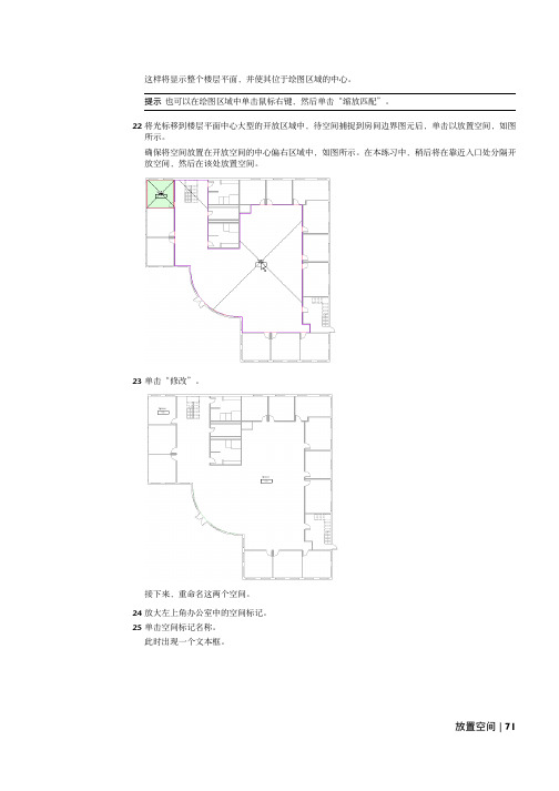
这样将显示整个楼层平面,并使其位于绘图区域的中心。
提示也可以在绘图区域中单击鼠标右键,然后单击“缩放匹配”。
22将光标移到楼层平面中心大型的开放区域中,待空间捕捉到房间边界图元后,单击以放置空间,如图所示。
确保将空间放置在开放空间的中心偏右区域中,如图所示。
在本练习中,稍后将在靠近入口处分隔开放空间,然后在该处放置空间。
23单击“修改”。
接下来,重命名这两个空间。
24放大左上角办公室中的空间标记。
25单击空间标记名称。
此时出现一个文本框。
放置空间 | 71输入Office,然后按Enter键。
26双击空间标记编号,在文本框中输入101,然后单击绘图区域。
27重复此方法,将开放区域中的空间重命名为“Open 104”。
接下来,激活空间可见性。
28在视图处于活动状态的情况下,在键盘上输入VG。
29在“可见性/图形替换”对话框中的“模型类别”选项卡上,展开“空间”,然后选择“颜色填充”、“内部”和“参照”。
“内部”选项显示空间着色。
“参照”显示空间参照线(十字光标)。
“颜色填充”在应用时将显示空间颜色填充。
在稍后的练习中学习将颜色填充应用于空间。
30单击“确定”。
此时这两个空间显示在楼层平面视图中。
72 | 第 3 章机械系统在入口区域中放置空间需要在建筑入口旁的区域中放置空间,因为该入口区域的加热和制冷频率要比其余的开放空间要高。
入口区域仅以弧形墙为边界,因此此区域被视为半边界区域。
要在入口区域中放置空间,必须通过绘制空间分隔线来将此区域变成完全边界区域。
31在“1 - Mech”视图处于活动状态的情况下,输入ZR,然后围绕着弧形墙的上顶角绘制缩放区域,如图所示。
32在设计栏的“机械”选项卡上,单击“空间分隔”。
注意如果设计栏上没有“机械”选项卡,请在设计栏上单击鼠标右键,然后单击“机械”。
33在选项栏上执行下列操作:■确认已选中(绘制)、“链”和(线)。
■确认已指定0.00mm作为“偏移”。
■确认已清除“半径”。
Revit教程MEP

ME
Building Information Modeling
BIM 建筑信息模型化
可视化 设计
工程量 统计
可出 图性
设计检验 、线管综合 以及优化等
2
3
1
4
MEP能做什么?
BIM 建筑信息模型化
可视化 设计
BIM 建筑信息模型化
工程量 统计
方法1: 明细表统计
直接导出工程量清单
族 Family
风机盘管族
谢谢
THANK U
BIM 建筑信息模型化
软件介绍
BIM 建筑信息模型化
软件界面 快速访问工具栏
应用程序菜单 属性框
小工具栏
选项卡
项目浏览器
视图控制栏
工具栏/功能区
绘图区域
BIM 建筑信息模型化
软件界面
建筑 结构
MEP常用命令 系统
插入 注释
选项卡
分析 体量和场地
协作 视图 管理 修改
BIM 建筑信息模型化
给排水
管道绘制
系统选取
管道类型设置
BIM 建筑信息模型化
暖通空调
风管绘制
设备放置
BIM 建筑信息模型化
电气
1.导线、电缆桥架、线管、的绘制 2.电气设备的选取 3.照明设备的放置
BIM 建筑信息模型化
明细表
BIM 建筑信息模型化
Revit 碰撞检测
直接在revit上运行构件之间的碰撞检测
BIM 建筑信息模型化
BIM 建筑信息模型化
管线 综合
BIM在深化设计中的应用
电气专业 给排水专业
暖通专业 综合
BIM 建筑信息模型化
REVITMEP软件教程1快速入门(25页)
快速入门本节内容z简介简介本简介可帮助您学习使用 Revit MEP 2009 教程,并提供了产品的基本概念,包括:z Revit MEP 是如何工作的。
z使用产品时所用的术语。
z如何导航用户界面。
z如何执行产品中的某些常规任务。
本节内容z使用教程z了解基本概念使用教程在本课程中,将学习如何使用 Revit MEP 教程,包括如何找到培训文件,以及如何从样板文件中新建 Revit MEP 项目。
Revit MEP 教程窗口的“内容”选项卡会显示可用的教程标题。
在教程中展开一列课程的标题。
在课程中展开一列练习的课程标题。
注意将教程打印出来会有助于您在使用 Revit MEP 时易于参考其中的说明。
也可以通过单击 Revit MEP 中的“帮助”菜单 “网上文档”获取 PDF 格式的教程。
本节内容z访问培训文件访问培训文件培训文件是专门为教程的使用而创建的 Revit MEP 项目、样板和族。
在本练习中,将学习如何找到培训文件,以及如何打开并保存培训文件。
如何找到培训文件的位置?默认情况下,培训文件位于“C:\Documents and Settings\All Users\Application Data\Autodesk\RME2009\Training"。
在“Training"文件夹中,培训文件被分为 3 个文件夹:z Common:讲授概念时经常用到的一般文件。
这些文件与英制或公制单位无关。
常规文件的名称中含有前缀 c_。
z Imperial:指为使用英制单位的用户准备的文件。
英制文件的名称中含有前缀 i_。
z Metric:指为使用公制单位的用户准备的文件。
公制文件的名称中含有前缀 m_。
注意根据安装情况的不同,培训文件夹可能位于不同的位置。
联系 CAD 管理员可获得详细信息。
重要信息可在培训文件位置找到并访问教程中所使用的内容(如样板和族)。
尽管此内容可能安装在您计算机的其他位置,但本教程中使用的所有内容都包含在培训文件位置中,以确保所有读者都能访问正确的文件。
Revit MEP 空调及消防教学手册
協勤資訊有限公司Autodesk Revit MEP空調系統/ 消防系統教育訓練手冊目錄壹、建立機械系統(Mechanical System) (3)一、建置空調系統 (3)(一)放置基於主體的出風口 (4)(二)放置非基於主體的出風口 (11)(三)建立次級送風管系統 (18)(四)為次級送風管系統建立管網 (22)(五)手動建立管網 (31)二、建置機械設備用的管(Piping)系統 (38)(一)增設機械設備 (38)(二)建立管(Piping)系統 (43)(三)使用自動配置功能增設管 (49)(四)使用手動配置功能增設管 (58)(五)增設閥 (72)(六)調整管大小 (77)(七)檢查系統 (81)(八)檢查管系統 (83)貳、建立消防系統 (86)一、建置消防系統 (86)(一)增設撒水裝置 (86)(二)建立管系統 (92)(三)完成濕式消防系統 (98)(四)增設垂直供水管 (103)(五)修改管直徑 (109)壹、建立機械系統(Mechanical System)在本教學課程中,將學習如何使用Autodesk Revit MEP 軟體來規劃及設計空調系統。
還將學習如何建置空調系統和管系統。
您將為辦公建築設計機械系統(Mechanical System)。
該系統由冷卻水塔、水源熱泵(WSHP - Water Source Heat Pump)、送風管系統和回風管系統構成。
在建立機械系統時,將完成一系列課程和練習,學習在Autodesk Revit MEP 中建議使用的系統進行設計作業流程。
該作業流程從系統規劃開始,到系統建置結束。
按照建議的作業流程,將可獲得系統設計的最佳化操作經驗,同時瞭解Revit MEP 如何使系統設計更加具有效益。
本教學課程的目標是教學使用Autodesk Revit MEP來進行設計機械系統。
在本教學課程結束時,您將瞭解使用Revit MEP 設計機械系統的過程、方法和特別技巧。
Revit_MEP_2009实战教程
Revit MEP 2009实战教程前言RevitMEP软件是一款智能的设计和制图工具,能按工程师的思维方式工作。
使用Revit技术和建筑信息模型(BIM),可以最大限度地减少建筑设备专业设计团队之间,以及与建筑师和结构工程师之间的协调错误。
此外,它还能为工程师提供更佳的决策参考和建筑性能分析,促进可持续性设计。
使用由RevitArchitecture软件或RevitStructure软件建立的模型,展开无缝协作。
在任何一处进行变更,Revit MEP可在整个设计和文档集中自动更新所有相关内容。
Revit MEP——面向建筑设备及管道工程的建筑信息模型。
按照工程师的思维模式进行工作,开展智能设计借助对真实世界进行准确建模的软件,实现智能、直观的设计流程。
Revit MEP采用整体设计理念,从整座建筑物的角度来处理信息,将给排水、暖通和电气系统与建筑模型关联起来。
借助它,工程师可以优化建筑设备及管道系统的设计,进行更好的建筑性能分析,充分发挥BIM的竞争优势。
同时,利用Revit与建筑师和其他工程师协同,还可即时获得来自建筑信息模型的设计反馈。
实现数据驱动设计所带来的巨大优势,轻松跟踪项目的范围、明细表和预算。
借助参数化变更管理,提高协调一致利用Revit MEP软件完成建筑信息模型,最大限度地提高基于Revit的建筑工程设计和制图的效率。
通过实时的可视化功能,改善客户沟通并更快做出决策。
改善沟通,提升业绩创建逼真的建筑设备及管道系统的三维模型,改善与客户的设计意图沟通。
通过使用建筑信息模型,自动交换工程设计数据,从中受益。
及早发现错误,避免让错误进入现场并造成代价高昂的现场设计返工。
借助全面的建筑设备及管道工程解决方案,最大限度地简化应用软件管理。
目录一、认识Autodesk RevitMEP……………………………………………………1、RevitMEP简介2、RevitMEP中的基本概念与操作……………………………………………二、标高和轴网的创建…………………………………………………………1、标高的创建2、轴网的创建三、风系统设计1、房间属性的设置2、机械设备的载入、定位与属性设置3、风道末端的载入、定位与属性设置4、风管属性设置与绘制方法5、风管附件的载入、定位与属性设置四、水系统设计1、机械设备、卫浴装置、消防设备的载入、定位与属性设置2、水系统末端的载入、定位与属性设置3、水管属性设置与绘制方法4、水管附件的载入、定位与属性设置五、电气系统设计1、电气设备的载入、定位与属性设置2、照明设备及开关装置的载入、定位与属性设置3、电力线路的设计六、施工图设计1、添加平面注释2、添加立面注释3、添加剖面注释4、详图5、明细表统计6、尺寸标注7、布图七、设计表现一、认识Autodesk RevitMEP1、RevitMEP简介1.1、功能介绍暖通设计准则使用设计参数和显示图例来创建着色平面图,直观地沟通设计意图,无需解读复杂的电子表格及明细表。
创建和使用Revit MEP信息化族
1.6.5 轨线分割 /Trajectory Segmentation
仅适用于“放样”
选中几何形体>点击命令行“图元属性” 度” ……
>勾选“轨线分割” >设置“最大线段角
南京正华
南京正华
2 使用 Revit MEP 信息化族
2.1 建立 MEP 系统
2.1.1 调用信息化族 文件>从库中载入>载入族……
2 使用 Revit MEP 信息化族
2.1 建立 MEP 系统 2.2 明细表
3 上机练习- 创建组合式空调箱
南京正华
1.创建 Revit MEP 信息化族 1.1 选择样板
文件 >新建 >族… 普通的族使用“公制常规模型.rft”, “Metric Generic Model.rft” 基于面附着的族使用“基于面的公制常规模型.rft”, “Metric Generic Model face based.rft”
(System) 卫浴设备
(Domestic Hot Water) 家用冷水
(Fixture Units)
(Domestic Cold Water) 其他
(Other) 湿式消防系统
(Fire Protection Wet) 干式消防系统
流向
损失方法
进
未定义
(In) 出
(Out) 双向
(Bidirecti onal)
2.1.2 布置设备 将的族从项目浏览器托拽到摆放位置
南京正华
2.1.3 逻辑连接 先“子”后“父”,先“逻辑”后“物理”。 例如:选取散流器>点击命令行 创建送风系统>点击命令行
编辑系统……
2.1.4 物理连接 当完成逻辑连接后,创建物理连接-管道连接
基于BIM的REVIT综合布线设计实例教程教学课件(共11章)02 MEP设置

参数的默认标签文字。 • 配电盘总数中包括备件:指定为配电盘明细表中的备件添加负荷
值时,是否在配电盘总负荷中包括备件负荷值。 • 将多极化线路合并到一个单元:指定是否将二极或三极线路合并
到配电盘明细表中的一个单元中。
•“配电盘明细表”面板
•“配电系统”面板
2.2.5 电缆桥架和线管设置
• “电缆桥架设置”面板如图所示。 • “电缆桥架设置”面板中的选项说明如下。
• 为单线管件使用注释比例:指定是否按照“电缆桥架配件注释尺寸”参 数所指定的尺寸绘制电缆桥架管件。
• 电缆桥架配件注释尺寸:指定在单线视图中绘制的管件的打印尺寸。 • 电缆桥架尺寸分隔符:指定用于显示电缆桥架尺寸的符号。 电缆桥架
2.2.2 配线
• “配线”面板如图所示,配线表中的设置决定着 Revit 对于导 线尺寸的计算方式以及导线在项目电气系统平面图中的显示方式。
•“配线”面板
• “配线”面板中的选项说明如下。 • 环境温度: • 配线交叉间隙: • 火线/地线/零线记号: • 横跨记号的斜线: • 显示记号: • 分支线路导线尺寸的最大电压降: • 馈线线路导线尺寸的最大电压降: • 用于多回路入口引线的箭头: • 入口引线箭头样式:
•“电气设置”对话框
2.2.1 常规
• “常规”面板如图所示,可以定义基本参数并设置电气系统的 默认值。
•“常规”面板
• “常规”面板中的选项说明如下。 • · 电气连接件分隔符: • · 电气数据样式: • · 线路说明: · 按相位命名线路-相位A/B/C标签: · 大写负荷名称: · 线路序列: · 线路额定值: · 线路路径偏移:
Revit-Mep-培训教材课程

选项卡:分析
点击可检查现有的风管系统是否有错误 点击可检查现有的管道系统是否有错误 点击可检查现有的电力系统是否有错误
点击可在平面视图中放置风管图例 点击可在平面视图中放置管道图例
点击可打开“系统浏览器”视图
选项卡:管理
点击可打开“设计选项”对话框,新建和编辑设计选项 创建设计选项后可将选择的图元添加到设计选项集
风口与墙的距离
点选风口可在属性中设置高度
风口布置平面视图
绘制风管系统
点击“风管”按钮,选择所需风管类型连接设备和风道末端。
注意:风管类型属性中定义了风管三通和接头等管件的 优先连接类型,可根据需要进行调整;点击“放置 风管”中的“对正”按钮,在“对正设置”对话框 中可设置风管连接时的对正方式。
设置管件类型
E.导入相关出图图框
图纸视图
E. 另存为.RTE 样本文件。另存为—样本
建筑性能分析
1、空间的应用 2、冷、热负荷的计算
空调风系统三维视图
空调风系统平面视图
1、空间的应用
放置空间 设置空间属性 划分空调区
放置空间
选项卡“分析”--“空间” ,进入放置空间模式,可在所处的楼层平 面具有面积边界的区域手动放置空间.
控制过滤器的设置 控制链接模型显示设置
设置视图属性
“过滤器”选项卡可控制不同系统在视图中的可见性,两种方法的 同时应用可以方便的将多专业的视图分别显示。
系统名称
系统可见性控制 点击可添加系统
显示图案设置
绘制循环水系统 绘制排水系统
空调水系统三维视图
空调水系统平面视图
绘制循环水系统
进入“F1-水系统”视图,右键单击空调设备预留的管道接口,点 击“绘制管道”按钮即可绘制循环水系统,如出现“select connector” 对话框,可根据连接件的说明选择所需管口。
- 1、下载文档前请自行甄别文档内容的完整性,平台不提供额外的编辑、内容补充、找答案等附加服务。
- 2、"仅部分预览"的文档,不可在线预览部分如存在完整性等问题,可反馈申请退款(可完整预览的文档不适用该条件!)。
- 3、如文档侵犯您的权益,请联系客服反馈,我们会尽快为您处理(人工客服工作时间:9:00-18:30)。
1. 2.
3. 4.
对课程安排和讲授方式,如有任何意见,反馈给李博士或者万祖勇 随时欢迎反馈任何想法和建议!
REVIT MEP课程培训
3D design
王震
目录
Revit MEP 培训课程
1.样板文件
2.属性栏及项目浏览器重点知识点介绍 3.风管绘制 4.管道绘制 5.桥架绘制
样板文件
在Revit中“.rte”格式的文件为样板文件
1.样板文件 2.属性栏及项目浏览器重点知识点介绍
3.风管绘制
4.管道绘制
5.桥架绘制
管道绘制
管道系统绘制命令
管道绘制
管道布管系统配置
注意选择正确 的管段材质
管道绘制
管道布管系统配置
粗略模式
精细着色模 式
精细真实模 式
管道绘制
管道附件及卫浴
1.点击连接件可直接绘制出管 道 2.排水管出水连接件需要先用 立管连接后,才能水平绘制
样板文件中定义了新建项目中默认的初始参数(包括属性设置, 项目默认的度量单位,线型设置,显示设置,项目浏览器中的 楼层设置及默认载入项目中的族等)
属性栏重点知识点介绍
属性栏位置
属性栏重点知识点介绍
重要属性
属性栏重点知识点介绍
规程
属性栏重点知识点介绍
视图范围
属性栏重点知识点介绍
视图范围图示
注释标记
快捷键:TG
碰撞检查
ID查找
输入ID
添加图纸
左击拖入
导练习和目标调整说明
练习原则:以消化上课内容为主,讲授完内容之后练习相关内容 每个人的练习目标:
1.
2. 3.
项目图纸:华夏御府项目
结构范围:地下室+地上一层 机电范围:地下室
4.
建筑专业:可选,建议完成地上一层的建筑外围部分
项目目标: 分2组完成华夏御府项目的整体结构和机电模型 后期会给合理的时间完成整体模型 具体分组和如何分工合作,后期再议
风管绘制
添加机械设备 2.点击属性栏显示下拉 菜单,选择所需放置的 设备 1.点击机械设备
3.在楼层平面中放置到相应位置,并注意 调整偏移量
风管绘制
载入族
风管绘制
添加风管隔热层
风管绘制
添加风管隔热层 新建隔热层类型
右击复制,重命名
风管绘制
添加风管颜色
风管绘制
添加风管颜色
风管绘制
添加风管颜色
管道绘制
放置消防喷头
管道绘制
增加默认管径
注意:管段的尺寸必须和管材一 一对应,不同管材对应的默认管 径可能会不同
管道绘制
增加管道系统类型
重命名复制项
目录
Revit MEP 培训课程
1.样板文件 2.属性栏及项目浏览器重点知识点介绍
3.风管绘制
4.管道绘制
5.桥架绘制
剖面框
桥架绘制
桥架绘制方式方法与风管水管类似
1. 2. 3.
本次调整和培训说明
培训原则:以大家对上课内容的接受和应用为目标,课程内容和讲授 方式可相应的做调整
本次调整考虑了大家的模型实际进展和大家的反馈意见,经领导同意
后调整
接下来的培训注意事项: 大家需要安排合理的时间进行练习 练习过程中有任何问题可以在群里面问,如果没有立刻解决的问题, 万祖勇会协调安排老师帮忙解决
点击减号
风管绘制
参照标高
风管绘制
立管绘制 1.设定初始偏移量
2.确定起始端
3.确定偏移端,设置偏移高度,点击应用
风管绘制
插入风管附件 1.点击风管附件
2.选择需要插入的附件 3.放置到管段中,注意放置位置会变成蓝色线
风管绘制
1.点击风管附件
插入风道末端
2.选择风管 末端类型 3.选择是否安装的风管上
目录
Revit 2014 MEP 培训课程
1.样板文件
2.属性栏及项目浏览器重点知识点介绍
3.风管绘制
4.管道绘制 5.桥架绘制
风管绘制
风管绘制命令
点击
风管绘制
风管系统绘制步骤
风管绘制
风管类型名称
风管绘制
风管系统配置
风管绘制
尺寸标注线
风管绘制
弯头生成
风管变径
风管绘制
弯头与三通的变换
点击加号
风管绘制
添加风管颜色
1、链接建筑结构RVT 2、建立轴网标高,注意 标高是否一致 3、链接CAD,对齐并锁定 可以利用剖面确定风管高度 4、设置风管类型,确定 放置的设备,载入相 应族类型 5、编辑适当的族类型
注:可将CAD底图设置为前景
a、放置风管软接头族 B、放置消声弯头
目录
Revit MEP 培训课程