HWJKF-12J说明书
新基德壁挂式太阳能盘管换热水箱使用说明书
Shan Dong Sun Cupid Electrical Appliances Co.,Ltd.备注数量22111装箱单单位台个个个本膨胀螺钉ST10膨胀胶管12Ф壁挂式太阳能热水器名称安全阀说明书序号24135备注:衷心感谢您选用新基德壁挂式太阳能热水器!壁挂式太阳能热水器壁挂式太阳能热水器香港新基德电器,具有二十多年小家电研制经验,其OEM产品畅销欧美。
1997年新基德电器在国内建立了专业电热水器生产基地,为您制造具有国际品质的新基德电热水器。
年新基德立足于自身优势,开始专业生产分体壁挂式太阳能热水器。
相信通过我们不断的努力,一定会让您更加喜爱和信赖新基德分体!为了方便您的使用,请仔细阅读本使用说明书。
再次感谢您选用“新基德”。
由于产品的不断改进,您所得到的热水器可能与本说明书中的图示不完全一致,谨此致歉!2003GB4706.1《家用和类似用途电器的安全第一部分:通用要求》GB4706.12《家用和类似用途电器的安全储水式热水器的特殊要求》卧式机型机器得电即显示热水器实际水温。
(默认设定:时钟…12:00;加热温度…60℃;功率1500W)一、时钟设定(24小时制)首次按“时钟”键时,时钟的小时位数值闪烁,按“▲”或“▼”键设定当前的小时位数值;再次按“时钟”键,时钟的分钟位数值闪烁,按“▲”或“▼”键设定当前的分钟位数值。
每按一次“▲”或“▼”键,设定数值加或减1;持续按压,则数值以1的整数倍快速增加或减少。
二、温度设定按“调温”键,设定水温数值闪烁,然后按“▲”或“▼”键设定加热温度。
每按一次“▲”或“▼”键,设定数值加或减5;持续按压,则数值以5的整数倍快速增加或减少。
三、定时设置(24小时制)首次按“定时”键,时钟小时位的数值闪烁,按“▲”或“▼”键设定开始加热的小时位数值;再次按“定时”键,分钟位的数值闪烁,按“▲”或“▼”键设定开始加热的分钟位数值。
每按一次“▲”或“▼”键,设定数值加或减1;持续按压,则数值以1的整数倍快速增加或减少。
南通宏大 012复丝强力机说明书
非常感谢您选购“宏大”纺织测试仪器在使用本仪器前,请详细阅读和理解全部说明,并将其保存好。
若您在阅读本说明书后仍有无法解决的疑问和问题,请向本公司询问。
重要的安全注意事项:● 仪器应在规定的电源电压范围内使用(AC220V ±10%),否则会影响仪器正常工作,可能损坏仪器。
● 仪器必须有效接地,以确保人身安全。
● 仪器应在水平状态下工作。
● 仪器应避免在高温、高湿、振动环境中使用。
● 上夹持器系力值传感器部分,严禁冲击碰撞,否则会损坏传感器。
● 传动部分丝杆应定期加注润滑脂,建议每年不少于二次。
● 供气压力必须在规定气压范围内。
(6~8㎏/cm 2) ● 在装夹试样时,动作应协调,以防气动夹持器夹手。
重要提示:● 如试验数据出现异常,不需要该次数据,可按[删除]键删除本次数据。
数据不参与结算,但仍被打印在报表上。
● 如在拉伸过程中,发现纱线未夹紧,可按[返回/停止]键停止拉伸,夹持器返回起始位置。
● 由于电源干扰等原因,仪器可能出现“死机”现象(按任何键不起作用),请按[复零]键或关闭电源后重新开机。
● 如打印机电源未开启,也会出现“死机”现象,这时只需开启打印机电源即可。
● 如打印机缺纸或打印纸未装好,也会出现“死机”现象,这时需要重新装好打印纸。
HONG DA关于HD012电子复丝强力仪操作使用的特别说明由于HD012电子复丝强力仪的断裂伸长计测装置采用了高精度的光电码盘计数系统,其测量精度要高于原机械式复丝强力仪,而且二则的测量原理也不尽相同。
考虑到行业的传统性、特殊性,为此在伸长率测量方面增加一项特殊功能,即:伸长系数可以修整。
具体操作方法如下:1、开机自检正常后,按[打印]键进入伸长系统修整,屏幕显示:伸长修整系数。
2、用[]键或[ ]设置伸长系数的百分率,设置完华按进入工作界面。
系数修整范围:“-30%~+30%”,“O ”值为不修整。
注:伸长系数修整功能为隐蔽功能,工作时及一般设置参数时不显示,只有在开机自检正常后,按[打印]键才能显示,设置伸长修整系数。
充电式风扇夹克

前提是他们受到监护或接受了本
电器的相关安全使用指导并了解
涉及的危险。禁止儿童玩耍本电
器。禁止在没有监护的情况下由
儿童进行清洁和用户维护。 • 洗涤前,拆下风扇单元、电池固
定器并取出电池套管。仅洗涤夹
克部分。 • 请勿向风扇吹压缩空气。请勿将
小棍放入风扇单元。否则可能损
坏风扇和电机。
定。
保持电池最大寿命的提示
• 切勿重新给完全充电的电池套管 再次充电。过度充电会缩短电池 使用寿命。
• 在 10°C - 40°C (50°F - 104°F) 的 室温给电池套管充电。
• 充电前,允许灼热的电池套管冷 却下来。
• 如果长期不使用(超过六个月), 请充电电池套管。
• 为取得最佳寿命,电池套管使用 后必须完全充满电。
................ 阴凉处悬挂晾干。
.......................... 不可拧干。
.......................... 如需要பைடு நூலகம்低温熨烫。
.......................... 不可干洗。
.......................... 仅限于欧盟国家 请勿将电气设备或电池组与家庭 普通废弃物一同丢弃 ! 请务必遵守欧洲关于废弃电子电 气设备、电池和蓄电池以及废弃 电池和蓄电池的指令并根据法律 法规执行。达到使用寿命的电气 设备和电池组必须分类回收至符 合环境保护规定的再循环机构。
的地方使用风扇夹克。否则可能
会烫伤皮肤。也请避免在高湿的
地方使用。 • 不要踩踏、投掷或滥用风扇夹
克。 • 避免电气部件沾水。 • 禁止穿戴风扇夹克睡觉。体温陡
JKWA-12EJ 使用说明书

JKWA-12EJ型无功功率自动补偿控制器使用说明书一、产品概述本产品适用于交流0.4KV、50Hz低压配电系统无功补偿控制,整机符合《DL/T597-1996》标准。
JKWA-12EJ能够进行无功补偿模糊投切,具有实时监测电网参数、谐波保护及保护警示等功能。
二、使用条件海拔高度:≤2500米环境温度:-20℃~+70℃相对湿度:40℃时20%-90%大气压力:79.5Kpa ~106Kpa环境条件:周围介质无爆炸危险,无足以损坏绝缘及腐蚀金属的气体,无导电尘埃,安装地不易剧烈振动,无雨雪侵蚀。
三、型号说明JK W A12E J注:以上型号只在产品标牌中体现;四.安装调试1、安全提示1)电源输入和CT二次侧均会危害人身安全,所以操作人员在安装、调试及检修时必须遵照有关的安全操作规程,以确保人身设备安全。
2)接线时应选择合适的线径,并严格按照接线图进行正确接线、以保证操作的安全性和可靠性。
2、安装与接线先将控制器装入装置面板开孔(138mm×138mm)内,再将安装卡推进控制器左右两侧卡槽内,再紧固螺钉,将控制器固定在装置面板上。
接线图示如下:控制器后面板各端子号定义如下表:3、 调试说明 1) 面板说明端子号 状态 详解COM 控制公共端 输出该端子为其控制公共端 1-12 12路输出接交流接触器线圈 Ia-K 、Ia-L 输入 接L1相取样电流互感器 Ub 、Uc 输入 接L2、L3相取样电压(380V )U 、N本机工作电源(220V )设置△ 自动/手动JKWA-12EJ 型无功补偿控制器▽2)自动运行系统上电后,首先进入等待稳定状态,约10s左右,进入自动运行状态,此时液晶显示屏显示自动运行下的第一屏。
自动运行共有三屏,操作▲或▼键两屏之间循环切换。
第一屏显示功率因数(COS)、电压、电流;当显示为正功率因数时,表示滞后;当显示为负功率因数时,表示超前。
第二屏显示有功功率、无功功率、频率;第三屏显示电压谐波总畸变率THDu、电流谐波总畸变率THDi、温度;12路输出及投/切状态指示在每一屏上均有显示,当要投入某路电容器时,该路投入指示显示在液晶屏上。
海尔电子有限公司 产品说明书 - 海尔瑜珈暖房
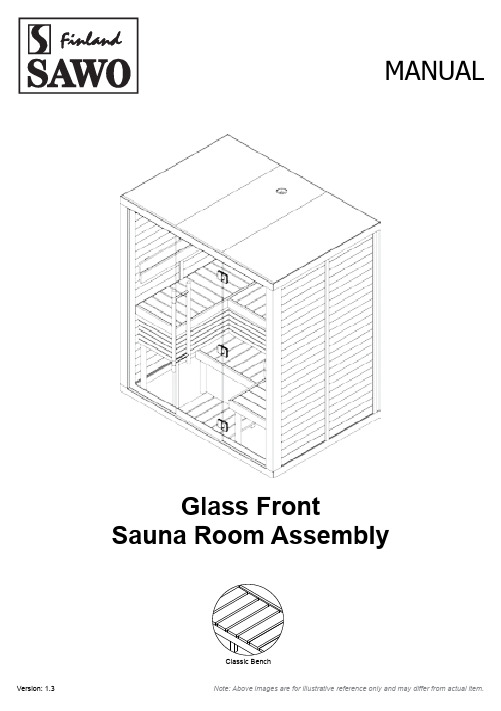
MANUALGlass FrontSauna Room Assembly124876543910121131233456789101111121212131615Parts List ExteriorParts List Interior*For room with full glass wall1. Ceiling Assembly2. Wall Elements3. Exterior Mouldings4. Top Exterior Mouldings5. Bottom Exterior Mouldings6. Main Base Frame7. Bolt Leveler8. Door Set9. Glass Wall (no holes)10. Glass Window (with holes for hinges)11. Front Outer L Mouldings 12. Front Solid Mouldings13. Front Bottom Outermost Moulding 14. Front Top Outermost Moulding 15. Glass Hinge 16. Glass top frame1. Backrest2. Top Bench Cover3. Lower Bench Cover4. Bench Cover frame5. Bench Cover Support6. Bench Siding Small7. Bench Siding Medium8. Bench Siding Large9. Legs large 10. Legs H11. Legs medium 12. Legs small6RM08-123Vertical Moulding 42mm thickHorizontal Moulding 75mm wide6RM08-123L Molding ScrewBolt LevelerTwist to adjust height6RM08-032Bench Siding6RM08-125 Upper and Lower Bench Frame6RM08-036Base Frame/Glass frame (top)6RM08-036Back RestCorner Moulding6RM08-123Vertical Moulding 6RM17-002Cam Lock BoltScrews for Room ExteriorScrews for Room Interior123401LevelerUse a Leveler to make the frame level to the floor Optional.After the base frame is leveled, place the ceiling assembly on the base frames to check if it fits nicely and leveled (great help after wall assembly)Do not seal the gap underneath the base frame. The gap is the passage way of the fresh air inside the sauna room.Make sure that the finish flooring where the sauna room will be placed is water proof and is incline towards the drain.Twist BOLT to adjust heightWall AssemblyFrames, Cam LockConnect base frames according to their corresponding numbers.Insert Cam Lock Bolts on Wall Panels.Cam Lock BoltShown on opposite side6RM17-002No. 1 is underneath the glass walls and door and numbers increase clockwise6RM08-036 ScrewIsometric ViewWall 2Wall 3Wall 4Wall 1Plan ViewWall1Wall2Wall 3Wall4Wall5Wall6Wall7Start from this cornerTongue and grooveMake sure cam lock is in open positionCam Lock OpenSide ViewCam Lock CloseCam Lock LocationAllen WrenchBefore moving on to securing the next wall element, make sure that both cam locks are properly securedWall AssemblyWall Attachments and SequenceAttach wall panels from the first corner (for easy installation). Take note of the grooves direction (groove facing left).Secure walls with cam locks.03Attached Glass Top Frame.046RM08-036Ceiling AssemblyAttach Ceiling Assembly via tongue to Groove.05Attach all mouldings except “Front top/bottom outermost molding and Outer L mouldings” (only after front glass is installed).06At this stage make sure all internal mouldings are attached as it will 6RM08-1236RM08-1236RM08-123Vertical Moulding 42mm thickInterior ceiling moulding6RM08-123Check that the ventilation hole is in the right position (refer to plan drawing for ventilation location)Ceiling to ceiling connection side view07Attach Bench Support at suggested height with screws,then place over the Bench Frame Assembly and screw to wall.Install sidings, bench covers and flooring.9Interior layout are all reversible, as shown on the illustration10Attach back rest to wall, attach leg support to bench frame.08Height dimensions should be taken in reference to the base frame. There are markers as well on the wall panels as reference for bench support mounting6RM08-036 ScrewScrew Cap6RM08-036 Screw Screw CapAttach top/lower bench covers, flooring and siding.The heater layout are all reversible, as shown on the illustration.Dthe frames to the wall.Height dimensions should be taken in reference to the base frame. There are markers as well on the wall panels as reference for bench support mounting.Attach top/lower bench covers,flooring and siding.CInterior layout are all reversible, as shown on the illustration.Dsupport frames to the wall.Height dimensions should be taken in reference to the base frame. There are markers as well on the wall panels as reference for bench support mounting6RM08-036 Screw Screw CapAnnoying sounds can be heard from improper hinge assembly, ensure correct assembly along with the plastic spacers.Annoying sounds can be heard from improper hinge assembly, ensure correct assembly along with the plastic spacers.Attach the glass walls where the glass frames ridges are located.11Then secure it with outermost solid molding with a screw.12Glass Wall AssemblyGlass Hinge componentsFaceplate Back R Plastic BushingsAllen WrenchFaceplate Front L Plastic gaskets Faceplate Front LPlastic shield Plastic divider Hexagonal Screw Faceplate Front RTake note of the holes. The glass wall holes has a square cutout in the middle.Don’t forget to insert the plastic gasket and plastic divider.Install from the inside.Attach the Faceplate Front R to the glass wall and secure with Faceplate Back R with screws.Loosely install the glass door then secure with Faceplate Back R.1314Glass Wall from inside.Glass Door from inside.Faceplate Back LFaceplate Back RFaceplate Front RMake and insert a 3mm thick wooden spacers underneath the glass door as well as the sides of the door (see illustration below). Then tighten the door hinges screws when glass door has even spacing all around.Note: Wooden spacers are not included in the package.15The glass door installation spacers are for easy installation of the glass door while keeping a 3mm even gap from the door jam.Remove the installation spacers after installing the door.3mm thickWooden SpacersAttached remaining Front outer L Moulding.After the installation and there is still uneven gaps on glass door, align it by rotating the abs bolt leveler until the glass wall swings freely.16Bolt LevelerRefer to door handle assembly manual.Attach the glass wall where the glass frames ridges are located.Follow glass door installation from Fig. 13-15.Then attached remaining Front outer L Moulding.Secure the glass wall with solid molding with a screw and insert top/bottom glass filler.Glass Wall Assembly (1414 LS/RS)Allen WrenchRefer to door handle assembly manual.Glass fi ller fi lls the small gap on top and below the glass door. Its reversible depends on the interior layout orientation.ACElectrical / Wiring LocationsElectrical Conduit Locations:For heater and regulating sensorFor sauna light switch and heater control For sauna lightWire Installation:1. Install junction / utility box into the ceiling roof as indicated.2. Insert wires into the electrical conduit designated for the sauna light switch (for NB heaters) or sauna control unit (for NS heaters).3. Insert wires into the electrical conduit designated for the heater (see technical detail).Extra wire jacket is provided for hooking up single wires to the heater. Disregard the extra wire jacket if you are using a rubber cable that is specifi ed in the heater’s manual.4. Tapping of wires will be done at the junction box.17Light Switch / Heater ControlConduitConduits are on both sides for light, controls and heater.Separate Control Installation (NS model heaters only)Sensor InstallationLight InstallationA conduit pipe is provided for the control unit.If wanting to fl ush the control unit into the wall, cut a hole according to your control unit’s specifi cations. See heater control manual.Note: Sensor installation is for Separate control heater models only.A pre-drilled hole for the sensor is provided for separate control heaters.Sensor is placed directly above the heater.Refer to the heater control instruction manual for the sensor installation.The wall has a pre-drilled hole(s) for the lights. Insert wire(s) to the conduit(s) provided for thelights.When ordering sauna room with NB heater, adimmer switch is provided for the light(s).When using NS heater, refer to the heater control instruction manual for the light installation.You can hide the power controller on the top of the sauna room.181920Conduit to control unitConduit locationPower ControllerControlControl unit must not be fl ushed to the wall, near or on the wall where the heater is installed.Use control unit interface holder if necessary.Refer to heater control instruction manual for wiring connections.。
长春集舒科技 WK 系列大功率激光二极管恒温控制器 说明书

WK系列大功率激光二极管恒温控制器使用说明书长春集舒科技有限责任公司2009年8月版权声明本手册所含全部文字与图片都受到知识产权保护,版权属于吉林大学电子技术开发中心。
本手册内的任何章节及图片不得在没有长春集舒科技有限责任公司授权之下做出任何复制、重组,或是翻译成其它语言。
本手册所叙述的内容与图片在印制之前已经完全校正过。
但因长春集舒科技有限责任公司不断地改善产品的品质、特性,吉林大学电子技术开发中心有权在未来修改产品的规格、特性及操作过程时,不必事先通知。
长春集舒科技有限责任公司地址:中国·长春市高新开发区硅谷大街4000号创业大厦415室邮编:130012网址:目录一、合格与担保 (3)二、安全要求及标志 (3)三、产品描述 (4)四、前面板简介 (6)五、后面板简介 (10)六、操作说明i.TEC和NTC输出端口连接 (11)ii.操作步骤 (11)七、操作举例 (12)八、技术支持及售后服务 (12)一、合格与担保合格长春集舒科技有限责任公司确认从公司发运时产品符合所公布的技术指标,符合国家标准。
担保长春集舒科技有限责任公司的仪器产品从发货之日起,对于材料和制造工艺的缺陷承担二年的担保。
在担保期内,对于确证有缺陷的产品,我公司将予以修理或更换。
(有关担保的详细资料,在购销合同中予以说明)二、安全要求及标志总则在使用本仪器前,操作人员必须详细熟悉产品及相关文件中的安全标记和说明。
本产品为一类安全仪器(带有保护接地端)。
安全注意事项(1) 搬运或储藏时应避免重压或震动;(2) 在损坏或无法正常工作,无专业技术人员在场时,不应随便自行拆机,以免影响其特性上的改变;(3) 注意所使用的电源电压220V,及保险丝的规格(250V,2A);(4) 本机使用三项电源,确保本机外壳与电源的良好接地。
(5) 操作环境范围0℃-40℃,应避免在高温、高湿度及强磁场干扰的场合下使用;(6) 如不遵守可能造成人身伤害或死亡,在警告符号符号要求的条件未完全理解或满足之前,切勿轻率操作。
简支梁试验机使用说明书
简支梁试验机使用说明书声明感谢您选择本公司数显简支梁冲击试验机!您能成为我们的客户是我们莫大的荣幸。
本公司不仅给您提供质量优异的产品,而且将为您提供满意的服务!为了您能更熟练地使用本试验机,我们随机配备了说明书。
本手册主要介绍本设备有关的结构原理、设备安装、操作方法以及安全注意事项等方面的知识。
特别提示:有时为了提高设备的性能,我们会对电气控制部分或机械部分作一些改动,这样可能会产生操作系统与使用指南在某些细节上不一致的情况。
在此声明:您所购买试验机随机配备的说明书以该试验机实际配备为准。
在编写本手册时,我们难免有错误和疏漏之处,请多加包涵并热情欢迎您提出宝贵意见或建议。
本手册的内容如有变动,恕不另行通知。
本手册版权所有;本手册的任何部分未经本公司书面许可,不得以任何方式影印、复印或翻译成其它语言。
★特别声明:根据客户具体要求不同,具体配置见装箱单。
本说明书不能作为向本公司提出任何要求的依据。
本说明书的解释权在本公司。
目录安全守则1摆锤在扬摆过程中尚未挂于挂摆机构上时,工作人员不得在摆锤摆动范围内活动或工作,以免偶然断电后发生危险2非专业或授权人员,禁止拆卸机器,否则一切后果自负3长期不用时必须拔下电源插头第1章产品信息1.1.概述XBL系列液晶数显简支梁冲击试验机是对硬质塑料、尼龙、硬橡胶、电气绝缘材料等非金属材料在动负荷下抵抗冲击性能进行检测的仪器,是非金属材料生产厂家、质检部门必备的检测仪器,也是科研单位进行新材料研究不可缺少的测试仪器。
本公司XBL系列数显简支梁冲击试验机可对试验结果进行打印输出等功能。
1.2.主要特点1.2.1.本机采用半自动化控制,操作简便、工作效率高。
1.2.2.本机所配的专用液晶显示屏可显示即时信息。
1.2.3.可打印输出。
1.3执行的标准1.3.1SO179—2000《塑料—硬质材料简支梁冲击强度的测定》1.3.2GB/T1043—2008《硬质塑料简支梁冲击试验方法》1.3.3JB/T8762—1998《塑料简支梁冲击试验机》1.3.4GB/T18743-2002《流体输送用热塑性管材简支梁冲击试验方法》(适用于管材件)1.4JZL机型主要技术参数1.4.1.1.冲击能量:简支梁5J、15J、50J或最大冲击能量由用户指定。
新乡万新电气--HWJKF-12F型低压无功补偿智能控制器 用户手册

HWJKF-12F型低压无功补偿智能控制器用户手册User’s Manual 中国·万新声明本公司担保在正常使用和保养的情况下,其产品没有材料和工艺上的缺陷,但不承担运送途中发生的损坏。
一年的担保期由产品发货之日算起。
如需要保修服务,请与本公司售后服务中心联系。
如果经售后认定产品故障是由于疏忽、误用、污染、修改、意外或不当操作或处理状况而产生,包括未在产品规定的额定值下使用引起的过压故障;或是由于机件日常使用损耗,则本公司会估算修理费用,在获得买方同意后再进行修理。
在准备安装、操作、服务或维护前,请认真阅读本手册。
版权所有,未经本公司之书面许可,本手册中任何段落、章节内容均不得被摘抄、拷贝或以任何形式复制与传播,否则一切后果由违者承担。
本公司保留一切法律权利。
本公司保留对本手册所描述之规格进行修改的权利,恕不另行通知。
订货前,请垂询本公司或当地代理商以获悉本产品的最新信息。
目录产品简介··············- 1 -命名 (2)产品简介 (2)功能特点 (2)控制策略 (4)技术参数 (4)使用环境条件 (5)安装与接线·············- 6 -安装说明 (7)前面板图 (7)后面板图 (8)接线说明 (8)操作说明··············- 9 -【数据显示界面】操作说明 (10)【参数设置界面】操作说明 (11)附录·············- 14 -附录A调试注意事项 (15)附录B公司简介 (17)附录C其他产品 (18)附录D联系我们 (19)产品简介命名产品简介HWJKF-12F型低压无功补偿智能控制器以高速微处理器为控制核心,其功能强大、抗干扰能力强、运算速度快,产品采用贴片工艺制造。
威斯康jkwf-12说明书
JKL7FJKL7F-12-12智能无功功率自动补偿控制器1JKL7F-12智能无功功率自动补偿控制器使用说明书一、一、概述概述JKL7F-12智能无功功率自动补偿控制器(简称:控制器)是低压配电系统补偿无功功率的专用控制器。
本控制器采用美国最新无功功率控制专用芯片,控制器抗干扰能力强,适应各种不同参数配电系数,运行稳定可靠、补偿彻底、操作简单。
二、二、型号说明型号说明JKL7F-7F-1212□特殊功能最大的控制路数设计序号取样物理量:L无功电流W无功功率G功率因数控制器代号三、三、使用条件使用条件1.海拔高度:≤2OOOm;2.环境温度:-25℃~50℃;3.相对湿度:85%(当25℃时);4.周围环境:无易燃、易爆的介质存在,无导电尘埃及腐蚀气体存在。
四、功能特性1.控制信号:采用功率因数和无功电流两物理量进行综合控制;2.操作简单:通过三个键操作,可以达到自动运行、手动投切、参数设定;3.电流判别:电流输入不用考虑极性,能自动判别转换;4.路数通用:投切路数由用户按需设定;5.数据保存:当改变设定参数后失电时,设定参数不会丢失,数据能永久保存,上电时参数不用重新设定;6.适应性强:控制器自动适应不同参数配电系统,无须提供电流互感器变比和补偿电容器的容量;7.过压保护:当电网电压超过设定值时,自动快速逐级切除已投入的电容器组;8.低无功封锁:电网无功量低于一组电容器1.1倍的补偿值,既使COSφ值小于设定值,为避免投切振荡而不投入补偿电容器组;9.低负荷封锁:当电流信号小于设计容量5%时,封锁电容器的投入,同时按设定延时逐级切除已投入的电容器组。
10.切投时间间隔自锁:为了防止电容器因放电不完全,引起切投过电压,当同一组电容器切投动作时间间隔小于电容器放电时间不投入,待时间间隔大于1分钟后才能投入。
五、技术参数1.工作电压:22OV/380VAC±20%5OHz;2.输入电流:≤5A;3.输出触点容量:25OV/5AAC38OV/3AAC;4.工作方式:自动循环,连续工作;5.投入门限:大于1.1Ic,并小于COSφ设定值;5.切除门限:超前;6.C0Sφ设定:0.90~O.99可调;7.延时设定:10~99s可调;8.过压设定:210~270V/、410~470V可调,电压回差8~10V;9.路数设定:1~7、1~10、1~12可调;10.执行标准:JB/T9663-1999六、输入及接线输入及接线1.输入电流必须取自配电总屏电流互感器的信号;2.输入信号如取A相,则输入电压必须取B、C相,即:电流信号无论取那一相,电压输入必须取另外两相;3.接触器线圈电压为380V时,P点与B点相接(见接线图),线圈电压为2200V时,P点与N 点相接。
冷却干燥机产品说明书
It is the responsibility of the user to ensure that the specifications provided for the selection of the unit or components and/or options are fully comprehensive for the correct or foreseeable use of the machine itself or its components.
The user is responsible for analysing the application aspects for product installation, and following all the applicable industrial and safety standards and regulations contained in the product instruction manual or other documentation supplied with the unit.
Tampering or replacement of any parts by unauthorised personnel and/or improper machine use exonerate the manufacturer from all responsibility and invalidate the warranty.
【精编范文】海格仪表说明书-推荐word版 (8页)
本文部分内容来自网络整理,本司不为其真实性负责,如有异议或侵权请及时联系,本司将立即删除!== 本文为word格式,下载后可方便编辑和修改! ==海格仪表说明书篇一:DKJ执行机构说明书DKJ(ZKJ)角行程电动执行机构使用说明书一.概述DKJ(ZKJ)型角型程电动执行机构采用“S”型电动执行机构开发的新技术:用精密专用传感器和专用电路组成WF-S位置发送器。
因此电动执行机构不仅在可靠、精度、负载能力、信号品质等性能方面比原来产品有了很大提高,而且对使用环境条件的拓宽,更具有十分重要的意义。
DKJ(ZKJ)角行程电动执行机构不仅可以和Ⅲ型控制单元仪表配套使用,而且还可以和新开发的S型控制单元仪表进行配套,使整个控制系统更加稳定、可靠、性能更好,功能更多。
因此用户可根据系统对DKJ型电动执行机构的要求,自动选择控制单元仪表,组合成一个控制单元系统。
DKJ角行程电动执行机构具有以下特点:1.电动执行机构位置发送器采用具有1/250分辨能力的高可靠性传感器。
输出电流Ⅱ型0~10mA DC,Ⅲ型4~20mADC。
2.电动执行机构位置发送器输出信号的负载能力强,负载能力≤750Ω 3.用户可以自由选择带行程限位机构,且组装调试方便,定位准确,重复性好。
4.交流伺服电动机具有阀用电动机特性,起动力矩大,能承受频繁的启动及短时间的堵转。
且附有制动器。
5.减速器采用少量行星齿轮传动,具有速比大、体积小,重量轻、效率高等优点。
6.位置发送器采用集成电路技术、功耗少,温升低,具有恒流输出特性,输出信号可以是4~20mA(DC)或0~10 mA(DC),14线对外接线插座达到GB4208规定的IP65标准7.具有0~90C范围内行程控制开关和接点输出通、断信号。
8.调整反零位(20-4)mADC、(10-0)mADC,只需将模块(1)、(3)两点接线对调。
二.用途DKJ型角行程电动执行器可以与变送器、DDZ-Ⅱ型、Ⅲ型调节仪等仪表配套使用,自动地操纵风门挡板、蝶阀、球阀等调节机构,完成自动调节任务,或配用电动操作器实现远方手动控制。
天车防碰撞装置使用说明
JGF型与HWF型天车防碰撞装置使用说明太原奇拓电子科技:0351―7024303JGF(HWF)型天车防碰撞装置使用说明天车在同一轨道上行驶,有可能会发生碰撞,造成人员和设备的事故。
所以需要防碰撞装置及时提醒操作人员注意,防止事故的发生。
一、产品型号及组成〔一〕产品型号1.JGF〔激光〕型天车防碰撞装置JGF-1型:双向单点控制JGF-2型:双向双点控制2.HWF〔红外〕型天车防碰撞装置HWF-1型:双向单点控制HWF-2型:双向双点控制〔二〕本产品由以下3局部组成:1、控制器〔主机〕控制器的功能主要是将激光〔红外〕传感器接收到的信号进展处理,根据检测到的距离,作出相应的报警和继电器的动作。
2、激光〔红外〕距离检测器激光〔红外〕距离检测器的功能是将发射光束射到反射板,并接收反射板所反射回的信号。
从而提供给主机计算天车到被测物体的距离。
3、反射板反射板的功能是以最小的损耗,将激光定向反射。
二、产品性能产品JGF-1型和HWF-1型是双向单点控制传感器,控制距离为15米范围内〔可根据用户要求调整距离〕,只控制一点距离。
左右各有一路继电器输出供用户减速或停车使用。
产品JGF-2型和HWF-2型是双向双点控制传感器,控制距离为5米内和15米内〔可根据用户要求调整距离〕。
15米时开场报警,左右各有一路继电器输出供用户选择使用,是否参与减速或停车,由用户自己确定。
5米时左右各有一路继电器输出供天车停车使用。
三、产品技术指标1、工作电压:AC220V,50HZ2、功耗:≤10W3、检测距离:15M〔5M〕4、检测距离误差:≤10%5、工作环境温度:–20℃―60℃6、外形尺寸:控制器205×130×86距离检测器150×120×55反射板84×84×8反射胶贴120×120四、安装和调试方法1、距离检测器〔带强磁〕吸附在天车边缘,反射板〔带强磁〕吸附在对面的物体上〔反射胶贴在对面物体上〕,与距离检测器的传感器光轴对应,呈一直线,安装时可先用激光源辅助安装。
DFK-12型电动阀门控制器使用说明书
DFK-12型电动阀门控制器概述DFK-12电动阀门控制器是与电动阀门配合使用的产品,用以控制电动阀门的开启和关闭。
主要特点:1.控制电路采用直流低压控制,调试、操作安全,控制可靠,4位数码管开度指示准确直观。
2.机壳采用标准的仪表机箱,体积小重量轻,便于安装在控制屏上。
3.指示灯指示开阀、关阀、阀全开、阀全关、事故、保护、现场、远控等状态。
4.提供现场控制。
5.电动阀门发生过力矩(事故)或过热(保护)时声光报警,便于及时排除故障。
6.智能校准:对阀位开度的“调零”和“调满”校准时,无需标定电位器、无需用基准测量仪表进行复杂的调试,只要在阀门实际的“全关”和“全开”位置各按一次标定按键,便以新设定的区间自动准确的修正为000.0和100.0。
7.相位保护:以前,在现场接线,必须保证提供给执行器的交流电的相序正确,因为一旦相序错误,就会造成电机不正确的转动,进而损伤阀门和执行器。
现在用户完全可以省去这一烦恼,接线时不再需要考虑相序的问题。
当现场接线相位颠倒时,相同步器会自动地改正相位,以确保阀门按指令的方向来执行。
即执行器接到开命令时总是按预先设置的开方向转动,不会因为相序调换而向相反方向运行。
8.电机为AC220V的执行机构直接控制,电机为AC380V的执行机构需加AC380V的功率驱动装置。
技术数据1.工作电压:220V/50Hz2.控制电压:220V/50Hz3.控制功率:继电器输出。
容量:10A4.工作环境:z环境温度:-20~40℃z相对湿度:不大于80%(20±5℃)z周围不含有强腐蚀型、易燃易爆介质。
z外形及安装尺寸:160mm*80mm*125mm(W*H*L)z屏装开孔尺寸:152ˉ¹mm*76ˉ¹mm(W*H)前面板功能部件说明z开度显示—指示阀门开度0~100%z标定—阀门全开时“开”(红色)指示灯常亮,按下“标定”键1秒,以此时的检测数据作为一个开度初值(最大值),同时开度表指示为100.0,阀门全关时“关”(绿色)指示灯常亮,按下“标定”1秒,以此时的检测数据作为另一个开度初值(最小值),同时开度表指示为000.0,其它状态下此按键不起作用,标定后的开度初值断电保持z“现场”(红色)指示灯点亮,表示现场控制工作方式,此时,控制器面板上的“开”键、“关”键、“停”键均不起作用,可由“选择”键切换至“远程”控制工作方式z“远程”(绿色)指示灯点亮,表示远程(控制器面版)控制工作方式,可由“选择”键切换至“现场”控制工作方式z“开”(红色)指示灯闪动,表示正在开阀;亮起时表示阀全开z“关”(绿色)指示灯闪动,表示正在关阀;亮起时表示阀全关z“事故”(红色)指示灯点亮,表示事故—电动装置过力矩,灯亮同时控制器内蜂鸣器发声 z“保护”(红色)指示灯点亮,表示保护—过电流,灯亮同时控制器内蜂鸣器发声z“选择”—“现场”或“远程”控制工作方式选择按键,持续按下1秒,“现场”“远程”工作方式进行切换,“远程”或“现场”状态断电保持z“开”—在“远程”控制方式中,按下“开”键,可控制电动阀门由停止向全开方向运行直至按下“停”键或到阀全开位z“关”—在“远程”控制方式中,按下“关”键,可控制电动阀门由停止向全关方向运行直至按下“停”键或到阀全关位后面板功能部件说明z1~3端为二组现场控制输入连接端,其中1端为控制输入公共端,2端(常开)为现场开阀控制输入端,3端(常开)为现场关阀控制输入端,在“现场”控制方式下,分别控制开阀和关阀操作z4~8端为五组检测输入连接端,其中4端为检测输入公共端,5端(常开)为开到位检测输入端,6端(常开)为关到位检测输入端,7端(常开)为事故检测输入端,8端(常闭)为保护检测输入端z10~12端为开度检测连接端,其中12端为最大开度运行方向,10端为最小开度运行方向,11端为开度检测抽头端z13~14端为4-20mA阀位输入连接端,其中13端为4-20mA阀位正端,14端为4-20mA阀位负端z19~24端为电动阀门电机控制输出和电源连接端,其中22端为电源的保护接地端,23端、24端分别为AC220V电源中性线和火线输入端,21端为开阀和关阀控制的公共端,19端、20端分别为用于开阀和关阀控制的火线输出端特别说明如果没有外加热继电器(常闭)输出,请将4和8短接。
J系列称重机说明书

High sensitivity
Utilizing simultaneous 2 frequencies from 4 types allowing higher sensitivity measurements to detect contaminants
Easy initial settings and daily operation
Controller can be separated ɹfrom the main body PQUJPO
*Cable x length 10m
Reliability &Safety
Maintenance information function Reject verification function PQUJPO
Industry leading performance
Speed:
480ppm
max.
45% up*
Accuracy: Industry No.1
0.07 max.
±
g 65% up*
*Compared to conventional model
Easy operation
Higher visibility 10.4 inch color touch screen
Easy screen control & visibility
A highly visible and clear screen format for ease of operation
Removable Controller (option)
The control unit (screen) can be removed from the main body and located up to 10m away. In addition, adjustable angle of controller does not limit operator’s working place and improve the work efficiency.
FI12HBK冷凝机技术数据手册说明书
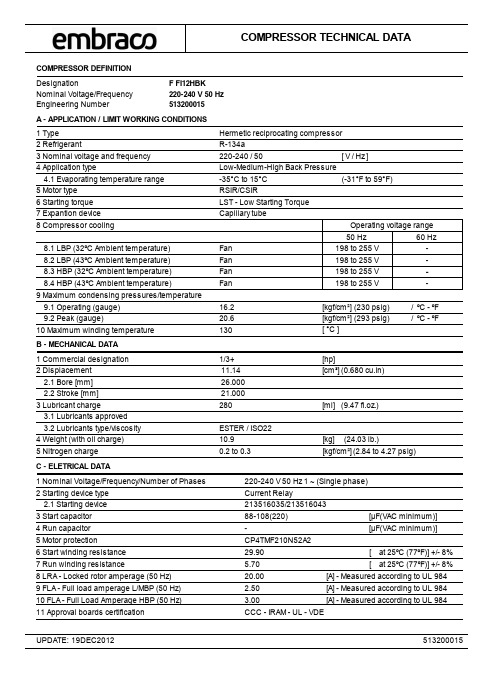
COMPRESSOR DEFINITION DesignationF FI12HBKNominal Voltage/Frequency 220-240 V 50 Hz Engineering Number513200015Hermetic reciprocating compressor -35°C to 15°C R-134a A - APPLICATION / LIMIT WORKING CONDITIONS 1 Type 4.1 Evaporating temperature range 2 Refrigerant8 Compressor cooling8.1 LBP (32ºC Ambient temperature) 8.2 LBP (43ºC Ambient temperature) 8.3 HBP (32ºC Ambient temperature) 8.4 HBP (43ºC Ambient temperature)9 Maximum condensing pressures/temperature 9.1 Operating (gauge) 9.2 Peak (gauge)Fan Fan Fan Fan16.220.6(-31°F to 59°F)(230 psig)(293 psig)[kgf/cm²][kgf/cm²]220-240 / 503 Nominal voltage and frequency Low-Medium-High Back Pressure4 Application typeRSIR/CSIR5 Motor type LST - Low Starting Torque6 Starting torque Capillary tube7 Expantion device / ºC - ºF / ºC - ºF10 Maximum winding temperature 130[ °C ][ V / Hz ]B - MECHANICAL DATA 2 Displacement[cm³](0.680 cu.in)11.141/3+1 Commercial designation [hp]3 Lubricant charge3.2 Lubricants type/viscosity 4 Weight (with oil charge)5 Nitrogen charge 0.2 to 0.3[ml](9.47 fl.oz.)[kg](24.03 lb.)[kgf/cm²](2.84 to 4.27 psig)280ESTER / ISO2210.9 2.1 Bore [mm] 2.2 Stroke [mm] 26.000 21.000 3.1 Lubricants approved C - ELETRICAL DATA1 Nominal Voltage/Frequency/Number of Phases 220-240 V 50 Hz 1 ~ (Single phase)11 Approval boards certificationCCC - IRAM - UL - VDE2 Starting device type 5 Motor protection 7 Run winding resistance8 LRA - Locked rotor amperage (50 Hz)9 FLA - Full load amperage L/MBP (50 Hz)29.905.7020.002.50CP4TMF210N52A2at 25ºC (77ºF)] +/- 8% [A] - Measured according to UL 984 [A] - Measured according to UL 9846 Start winding resistance 10 FLA - Full Load Amperage HBP (50 Hz) 3.00[A] - Measured according to UL 984Current Relay2.1 Starting device [at 25ºC (77ºF)] +/- 8% [-4 Run capacitor [µF(VAC minimum)]88-108(220)3 Start capacitor [µF(VAC minimum)]198 to 255 V -198 to 255 V -198 to 255 V 198 to 255 V--Operating voltage range 50 Hz60 Hz 213516035/213516043D - PERFORMANCE - CHECK POINT DATATEST CONDITIONS:TEST CONDITIONS:7.2°C (44.96°F)-23.3°C (-9.94°F)(Condensing temperature(Condensing temperature4492109011322751316319504 2562.791.96 6.198.914.262.251.072.611.25Cooling capacityCooling capacity+/- 5%+/- 5%[Btu/h][Btu/h][kcal/h][kcal/h][W][W][W][W]Current consumptionCurrent consumption+/- 5%+/- 5%[A][A]EFFICIENCY RATEEFFICIENCY RATE[kg/h][kg/h][Btu/Wh][Btu/Wh][kcal/Wh][kcal/Wh][W/W][W/W]+/- 7%+/- 7% @220V50Hz@220V50HzEvaporating temperature Evaporating temperature ASHRAEHBP32ASHRAELBP32FanFan54.4°C (129.92°F))54.4°C (129.92°F))Gas flow rate Gas flow rate +/- 5%+/- 5%Power consumption Power consumption +/- 5%+/- 5%E - PERFORMANCE - CURVES45ºC (+113ºF) )@220V50HzASHRAE32(Condensing temperature TEST CONDITIONS:FanEvaporating temperature °C (°F)[Btu/h][kcal/h][W][W]Current consumption +/- 5%[A][kg/h] 5905148817305182.9034.865019 1265 1471 480 2.75 29.41 4217 1063 1236 442 2.60 24.54 3495 881 1024 406 2.47 20.21 2853 719 836 2.35 370 16.41 2289 577 671 336 2.23 13.10 1383 348 405 272 2.05 7.87 1038 262 304 242 1.97 5.90 762 192 223 214 1.91 4.33 -30(-22) -25(-13) -20(- 4) -10(+14) -5(+23) 0(+32) +5(+41) +10(+50) +15(+59)[Btu/Wh][kcal/Wh][W/W] 11.402.873.3410.46 2.64 3.07 9.52 2.40 2.79 8.60 2.17 2.52 7.69 1.94 2.25 6.80 1.71 1.99 5.12 1.29 1.50 4.35 1.10 1.27 3.62 0.91 1.06 -15(+ 5) 1799 453 527 303 2.13 10.26 5.94 1.50 1.74 3.13 -35(-31) 553 139 162 187 1.87 2.94 0.74 0.86EFFICIENCY RATE+/- 7%Gas flow rate+/- 5%+/- 5%Power consumption +/- 5%Cooling capacity55ºC (+131ºF) )@220V50HzASHRAE32(Condensing temperature TEST CONDITIONS:FanEvaporating temperature °C (°F)[Btu/h][kcal/h][W][W]Current consumption +/- 5%[A][kg/h] 5565140216315753.1232.854729 1192 1386 528 2.93 27.71 3972 1001 1164 483 2.75 23.11 3292 830 965 440 2.59 19.03 2687 677 787 2.44 398 15.44 2155 543 631 357 2.30 12.33 1300 328 381 282 2.08 7.40 974 245 285 247 2.00 5.54 713 180 209 215 1.93 4.05 -30(-22) -25(-13) -20(- 4) -10(+14) -5(+23) 0(+32) +5(+41) +10(+50) +15(+59)[Btu/Wh][kcal/Wh][W/W] 9.692.442.848.97 2.26 2.63 8.23 2.08 2.41 7.50 1.89 2.20 6.76 1.70 1.98 6.03 1.52 1.77 4.62 1.16 1.35 3.95 1.00 1.16 3.31 0.83 0.97 -15(+ 5) 1693 427 496 319 2.18 9.65 5.32 1.34 1.56 2.91 -35(-31) 514 130 151 184 1.89 2.71 0.68 0.79EFFICIENCY RATE+/- 7%Gas flow rate+/- 5%+/- 5%Power consumption +/- 5%Cooling capacityE - PERFORMANCE - CURVES65ºC (+149ºF) )@220V50HzASHRAE32(Condensing temperature TEST CONDITIONS:FanEvaporating temperature °C (°F)[Btu/h][kcal/h][W][W]Current consumption +/- 5%[A][kg/h] 5394135915816333.3631.844583 1155 1343 578 3.13 26.85 3847 970 1127 525 2.91 22.38 3183 802 933 474 2.71 18.40 2590 653 759 2.53 424 14.89 2065 520 605 377 2.37 11.82 1212 305 355 289 2.10 6.90 880 222 258 249 2.00 5.01 608 153 178 211 1.92 3.46 -30(-22) -25(-13) -20(- 4) -10(+14) -5(+23) 0(+32) +5(+41) +10(+50) +15(+59)[Btu/Wh][kcal/Wh][W/W] 8.512.142.497.94 2.00 2.33 7.34 1.85 2.15 6.73 1.70 1.97 6.09 1.54 1.79 5.45 1.37 1.60 4.16 1.05 1.22 3.53 0.89 1.03 2.91 0.73 0.85 -15(+ 5) 1606 405 471 332 2.22 9.16 4.81 1.21 1.41 2.22 -35(-31) 395 100 116 175 1.87 2.32 0.58 0.68EFFICIENCY RATE+/- 7%Gas flow rate+/- 5%+/- 5%Power consumption +/- 5%Cooling capacityUniversal EG/F/AMEM version 2NoF - EXTERNAL CHARACTERISTICS1 Base plate2 Tray holder3 Connectors 3.1 SUCTION 8.2 +0.12/-0.083.1.1 Material Copper 3.1.2 Shape Straight 3.2 DISCHARGE 3.2.1 Material 6.5 +0.12/-0.08Copper 3.2.2 Shape Straight 3.4 Oil cooler (Copper) 3.3 PROCESS 6.5 +0.12/-0.083.3.1 Material 3.3.2 ShapeCopper Straight No3.5 Connector sealingRubber Plugs[mm](0.323" +0.005"/-0.003")[mm](0.256" +0.005"/-0.003")[mm](0.256" +0.005"/-0.003")[mm]。
湘仪动力测试仪器 PowerLink FC2012 电力测功机控制仪 说明书

FC2012电力测功机控制仪使用说明书长沙高新技术产业开发区湘仪动力测试仪器有限公司目录1、概述 (3)2、仪器功能和配置 (3)3、主要性能特点 (4)4、主要技术指标 (4)5、前面板 (5)5.1、参数显示 (5)5.2、键盘操作 (5)5.2.1、PID设置 (7)5.2.2、TF标定 (7)5.2.3、JC标定 (8)5.2.4、采样周期 (9)5.2.5、显示设置 (9)5.2.6、报警设置 (10)5.2.7、测量设置 (12)5.2.8、控制设置 (12)5.2.9、启动设置 (14)5.2.10、RS232设置 (14)5.2.11、CAN通讯 (14)5.2.12、系统设置 (15)5.2.13、恢复默认值 (15)6、仪器标定 (18)7、仪器操作 (19)8、后面板接线 (21)9、附录1测功机信号调理模块 (24)说明书最后更新:2009.4.24.1、概述请注意:FC2012控制方式键最后两个从左到右分别是n1/M,n1/P,早期的面板上印刷有误。
FC2012电力测功机控制仪与HBM扭力环及与其信号兼容的扭矩传感器,电力测功器,变频器,油门执行器,智能油耗仪等配套使用,用来测量和控制发动机的扭矩,转速,功率,油耗等参数。
仪器采用数字增量式PID控制算法,控制精度高。
扭矩,转速设定采用光电式数字电位器,无接触,无磨损,长寿命。
无记忆,便于实现控制方式的无扰动切换。
输入,输出,电源全部隔离,具有很高的抗干扰能力。
采用先进的CAN现场总线技术。
CAN先进的“无主”结构,使系统的构筑和扩充非常的方便。
与变频器连接采用RS485接口,直接用数据通讯,避免了模拟信号带来的干扰等问题,使系统运行更可靠,智能化程度更高。
仪器支持正,反转双向调零。
仪器自带汉字库,配合液晶显示器和简洁的键盘,使仪器的人机对话十分轻松。
菜单式和选项式的操作,简单明了。
2、仪器功能和配置1一个扭矩测量通道,一个转速测量通道2一个D/A输出口,用于油门控制3一个485口,用于变频器控制4一个CAN口,用于与计算机,油耗仪,采集仪等通讯52路开关量输出(保护停车,紧急停车)64路开关量输入(备用,保护停车,紧急停车,正反向调零)3、主要性能特点●采用先进的CAN现场总线技术●非接触,无磨损的数字电位器给定方式●数字增量法控制发动机转速/转矩●各种控制模式的无扰动切换,预设7种控制模式,可实现反拖控制●对变频器的控制使用485,避免了使用模拟信号可能带来的干扰,并使控制更加智能化●输入,输出,电源全隔离,高抗干扰能力●正,反转双向调零●扭矩,转速超限声光报警●使用液晶显示器人机界面友好●模块化设计使结构简化,具有无可比拟的可靠性和可维护性4、主要技术指标①扭矩测量信号类型:差分信号频率范围:20Hz-20kHz采样时间:10ms,20ms, 50ms可选量程范围:-32768至+32767测量精度:±0.2%F.S②转速测量信号类型:差分信号频率范围:20Hz-200kHz采样时间:10ms, 20ms, 50ms可选量程范围:0至+32767测量精度:±1rpm③油门控制输出D/A转换精度: 12位电压输出:输出阻抗:100Ω电流输出:负载电阻:<300Ω④变频器控制输出232端口MODBUS协议USS协议5、前面板扭矩仪前面板上布置有一块130×35mm的液晶显示屏和一组键盘,如图1、2所示。
微型氢浆分离器与氮浆分离器用户指南说明书
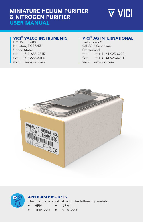
TABLE OF CONTENTSSpecificationsTheory of Operations Power Supply Requirements PG. 3 PG. 3 PG. 4InstallationActivationOperationRemoving the HPM or the NPM from the System PG. 4 PG. 5 PG. 5 PG. 5 PG. 2 PG. 4 PG. 6PG. 61|Virtually all commercial gas chromatographs contain certain components at levels which are unsuitable for low ppb universal analyses (although they may not be problematic for flame ionization and thermal conductivity detectors). For example, unheated molecular sieve traps are certain to contaminate the carrier gas with CO2 and H2O.The VICI ®Miniature Helium Purifier (HPM) and Miniature Nitrogen Purifier (NPM) are designed to address this situation, providing “point-of-use” carrier gas purification to sub-ppm levels of gaseous impurities. When installed in a gas chromatograph’s flow path immediately upstream of the injector, the HPM/NPM will remove any contaminants introduced by flow controllers, elastomeric tube seals, pressure regulators, crude traps, or other system components that are not completely clean and leak-tight. The GC’s actual carrier inlet should be supplied from the HP2 inert gas purifier which ships as part of the Valco pulsed discharge detector system. No other carrier purifiers, including oxygen, moisture, and hydrocarbon traps, should be used; they are likely to introduce one contaminant as they remove another.WARNING: This product is not for use with oxygen – either pure oxygen or gases with a significant proportion of oxygen. The purifier’s gettering alloy is pyrophoric at operating temperature. Use with significant amounts of oxygen can result in combustion of the material, potential damage to the surrounding area, and possible injury.In no event shall Valco Instruments Co. Inc. be liable for any direct, indirect, special, incidental, or consequential damage, whether based on contract, tort, or any other legal theory and whether advised of the possibility of such damages.1. INTRODUCTION| 21.1 Specifications1.2 Theory of OperationThe purification substrate in the VICI purifiers is a non-evaporable gettering alloy. The alloy must be heated so that the oxide layers on the particle surface are elim-inated. This process must be performed under a vacuum or in at atmosphere of helium (for the HPM) or nitrogen (for the NPM).Although the gettering alloy will purify even at ambient temperatures, raising the temperature vastly improves the life span and efficiency of the alloy. However, the elevated temperature causes hydrogen generation, which is trapped only at tem-peratures below 250°C. Accurate temperatures are maintained with the use of the precision 24 VDC power supply which is supplied with the HPM/NPM.3|1.3 Power Supply RequirementsAs stated on the purifier, the power supply must conform to EN 61010-1: Section F.2.1 Limited circuit. This section mandates that the power source must be limited to 42.4 VDC or less (open circuit). In addition, the energy must be limited by one of the following means:• The current under any condition of load, including short circuit, is not more than 8A measured after 1 minute of operation.• The source is rated or set to limit its power to 150 VA under any condition of load.• An overload protector or circuit component opens to interrupt the power output at a lower value than 150 VA under any condition including short circuit.2. INSTALLATION & OPERATIONThe VICI HPM and NPM are two part systems comprised of the purifier and the power supply. The purifier can be installed in any position. For best results, do not modify the fittings or tubing lengths; small particles which might be generated by such modifications are difficult to remove and can restrict the flow.1. Locate the HPM where the temperature will not exceed 40°C, and with at least a half inch of clearance around and above the purifier to prevent overheating.2. Disconnect the carrier supply line immediately upstream of the injector and connect this line to the inlet of the purifier.3. Connect the output line of the purifier to the injector.4. Purge the system for 5 to 10 minutes at 20 to 30 mL/min to eliminate air from the getter material.5. Insert the barrel connector of the power supply into the purifier.6. Connect the power supply to mains (115/230 VAC). The LED on the power supply should confirm power output.2.1 InstallationWARNING: The getter material should neverbe heated when air is present. | 42.2 ActivationWhen the purifier reaches operating temperature (in about 1 hour) the getter will be activated. Once the getter is activated, active gaseous impurities such as O2,H2O, CO, and CO2 (plus N2 for the HPM) are captured and chemisorbed on the getter surface. Only noble gas atoms are not affected. Once adsorbed, oxygen, carbon, and nitrogen atoms cannot be released by the getter material even at its melting point (1400°C), due to the formation of strong chemical bonds with the alloy atoms.Hydrogen atoms behave quite differently, diffusing into the getter material bulk more quickly than the other atoms and becoming almost uniformly distributed with-in the bulk.2.3 OperationIn normal operation the outside temperature of the purifier is warm, but should not be uncomfortable to the touch. The 24 VDC power supply maintains the purifier trap at a constant temperature, and should be located so that the illuminated LED can serve as a visual indicator of purifier operation.Removing the HPM or NPM from the SystemTo remove the purifier from the carrier gas line:1. Disconnect the power supply. Disconnect the output line from theinstrument while maintaining carrier flow.2. Allow about one hour for the purifier to cool. After it reaches ambient temperature, cap the output line and allow the purifier to bepressurized for several minutes.3. Remove the input line and immediately cap it. This maintains a carrier gas atmosphere on the gettering substrate, increasing its lifetime.To reinstall, follow the instructions in the Installation section at the top of page 3.5|3. ROUTINE MAINTENANCEWARNING: Do not try to open ormodify the purifier.In normal usage there is no maintenance required on the purifier or power supply. If the purifier shows signs of saturation it will need replacement. Replacement purifiers can be ordered from VICI using the following product numbers:• Helium purifier - HPM• Nitrogen purifier - NPMDisposing of the purifierTo dispose of this product, visit https:////returns.php, or email******************.Thepackageshouldbeclearlymarked“Traps for Disposal”.4. WARRANTYThis Limited Warranty gives the Buyer specific legal rights, and a Buyer may also have other rights that vary from state to state. For a period of 365 calendar days from the date of shipment, Valco Instruments Company, Inc. (hereinafter Seller) warrants the goods to be free from defect in material and workmanship to the original purchaser. During the warranty period, Seller agrees to repair or replace defective and/or nonconforming goods or parts without charge for material or labor, or, at the Seller’s option, demand return of the goods and tender repayment of the price. Buyer’s exclusive remedy is repair or replacement of defective and nonconforming goods, or, at Seller’s option, the repayment of the price.Seller excludes and disclaims any liability for lost profits, personal injury, interruption of service, or for consequential incidental or special damages arising out of, resuiting from, or relating in any manner to these goods.|6This Limited Warranty does not cover defects, damage, or non- conformity resulting from abuse, misuse, neglect, lack of reasonable care, modification, orthe attachment of improper devices to the goods. This Limited Warranty does not cover expendable items.This warranty is VOID when repairs are performed by a non- authorized service center or representative. For information about authorized service centers or representatives, write Customer Repairs, Valco Instruments Company, Inc, P.O. Box 55603, Houston, Texas 77255, or phone (713) 688-9345. At Seller’s option, repairs or replacements will be made on site or at the factory. If repairs or replacements are to be made at the factory, Buyer shall return the goods prepaid and bear all the risks of loss until delivered to the factory. If Seller returns the goods, they will be delivered prepaid and Seller will bear all risks of loss until delivery to Buyer. Buyer and Seller agree that this Limited Warranty shall be governed by and construed in accordance with the laws of the State of Texas.The warranties contained in this agreement are in lieu of all other warranties expressed or implied, including the warranties of merchantability and fitness for a particular purpose.This Limited Warranty supercedes all prior proposals or representations oral or written and constitutes the entire understanding regarding the warranties made by Seller to Buyer. This Limited Warranty may not be expanded or modified except in writing signed by the parties hereto.7||8。
- 1、下载文档前请自行甄别文档内容的完整性,平台不提供额外的编辑、内容补充、找答案等附加服务。
- 2、"仅部分预览"的文档,不可在线预览部分如存在完整性等问题,可反馈申请退款(可完整预览的文档不适用该条件!)。
- 3、如文档侵犯您的权益,请联系客服反馈,我们会尽快为您处理(人工客服工作时间:9:00-18:30)。
HWJKF-12J型低压无功补偿智能控制器使用说明书合肥华威自动化有限公司HE FEI HUA WEI AUTOMATIC CO.,LTD.目录一、简介 (1)二、技术参数 (1)三、使用环境条件 (1)四、控制器主要功能 (1)五、界面操作说明 (2)六、装置端子接线图(背视) (4)七、典型应用接线图 (5)八、装置调试说明 (5)九、装置外形及安装开孔尺寸: (6)一、简介HWJKF-12J型低压无功补偿智能控制器以高速微处理器为控制核心,其功能强大、抗干扰能力强、运算速度快,产品采用贴片工艺制造。
产品质量可靠,其通过与并联电容器装置配套,控制补偿电容器自动投切,以提高功率因数,提高电力变压器的利用效率,降低线损,改善电压质量。
控制器以电压(U)或无功功率(PF)为控制物理量(根据用户需求可灵活选择),可满足不同用户的需求。
当控制物理量为无功功率(PF)时,可根据实时的无功需量,进行电容器组的最佳匹配投切,使补偿效果达到最佳状态。
确保系统稳定、无投切振荡、无补偿呆区。
当控制物理量为电压(U)时,能根据当地的电压高低自动投切电容器组以调节电压。
二、技术参数l工作电压:交流200V~240Vl额定频率:50Hzl取样电压:AC220V ±20%三相四线l取样电流:0~5A三相四线 (总进线电流互感器二次侧)l控制输出:12路继电器常开出口 AC220V/3Al控制对象(即电容投切开关):电容型交流接触器l电容组合方式:12共;9共1分;6共2分;3共3分;4分l电容器容量设置:0kvar~200 kvar 级差1l CT变比比值设置: 10~600 级差 1l控制延时:0~600S三、使用环境条件l环境温度:-40℃~ +85℃;l相对温度:25℃时小于90%;l大气压力:79.5kPa ~ 106.0kPa(海拔2000m及以下)。
四、控制器主要功能1.控制功能l当以电压为控制物理量时u实测电压处于电压上下限之间时控制器维持现状不动作。
u实测电压高于电压上限时,延时开始计时,当延时大于预先设定值时,控制器发出切电容器命令。
u实测电压低于电压下限时,延时开始计时,当延时大于预先设定值时,控制器发出投电容器命令。
l当以无功功率为控制物理量时u当欠补且实测无功功率大于投入门限时,延时开始计时,当延时大于预先设定值时(10 s),控制器发出投电容器命令。
u当过补且实测无功功率大于切除门限时,延时开始计时,当延时大于预先设定值时(10 s),控制器发出切电容器命令。
2.显示功能(详见界面操作部分)3.装置闭锁功能u同组切投时间间隔不得小于180秒,否则将闭锁该电容器的投切操作。
4.过压欠压保护功能u当电压高于装置设定的过压保护值时,通过延时,装置发切除电容器命令,直到电压恢复正常,过压保护自动解除。
u当电压低于装置设定的欠压保护值时,通过延时,装置发切除电容器命令,直到电压恢复正常,欠压保护自动解除。
五、界面操作说明控制器共有两类界面:数据显示界面和参数设置界面“▼”:向后翻页(或减功能键)“▲”:向前翻页(或加功能键)“查询”:参数设置界面和数据显示界面切换“整定”:进入参数设置状态,参数设置确定键1)显示界面共16幅(开机后自动进入界面1)最左边一位数码管显示代码(依次为0~E),右边三位数码管显示实时测量值。
如下图所示:左面数码管右面数码管0 2 2 5在此界面下,按查询键进入参数设置界面,再按查询键返回数据显示界面,按上下键进行前后翻页。
从0~E 各页面显示的测量值分别为:u三相电压:0-Ua,1-Ub,2-Uc 单位: Vu三相电流:3-Ia,4-Ib,5-Ic 单位: Au三相有功功率:6-Pa,7-Pb,8-Pc 单位: kWu三相无功功率:9-Qa,A-Qb,b-Qc 单位: kvaru三相功率因数:C-COSa,d-COSb,E-COScu三相超前显示:A B C (过补时,显示当前超前相)2)参数设置界面共38幅在数据显示界面状态下按“查询”键,进入参数设置界面,这时“参数1”指示灯亮。
参数设置共有三种界面,分别用1、2、3表示。
参数1:对0~d共14项参数进行设置;参数2:对12路电容器的接线方式进行设置(共补、分补);参数3:对12路电容器的容量进行设置(kvar)。
进入参数设置界面后,可按上下键进行前后翻页选择设置内容(含参数1、2、3)。
当按下整定键后,“整定”指示灯亮,此时可以按上下键对参数进行加减,进行参数整定。
当再次按下整定键后参数保存,“整定”指示灯灭。
※参数1的各项参数设置说明如下:Ø参数1灯亮时,共有14项参数设置,各项参数含义如下表代码含义单位参数范围出厂设定值0 自动控制软开关(控制器自动运行/停止)——On / OFF On1 控制方式(无功功率/电压)——PF / U PF2 电压切除门限V 160~265 2503 电压投入门限V 160~265 2004 无功切除门限kvar 0~50 05 无功投入门限kvar 0~50 按需设置6 过压保护定值V 230~270 2557 欠压保护定值V 160~230 1808 组间时间间隔S 5~60 109 同组切投时间间隔S 0~600 300A CT(电流变比值,直接设置5的倍数)——10~600 20b 低功率因数闭锁定值——0~0.5 0.35 C 手动控制投入电容器组组0~11 按需操作d 手动控制切除电容器组组0~11 按需操作手动投切说明:手动控制时,按查询键进入参数1界面,参数灯1亮。
按下键翻页至C/d页,按整定键,整定灯亮。
此时再按上下键选择要进行投切的电容器组号,然后按整定键执行该组电容器的投切操作,整定灯灭,控制器面板上相应组号的电容器指示灯亮或灭。
要进行其他电容器组的手动投切操作,重复以上步骤即可。
在参数1的d界面,按下键可进入参数2界面,参数2指示灯亮。
此时可设置参数2的有关参数。
※参数2指示灯亮时,对12个输出支路电容器接线方式(共补或分补)分别进行设置。
一共有5种组合方式:12共;9共1分;6共2分;3共3分;4分。
其中“共”表示共补电容器;“分”表示分补电容器。
左面数码管中显示的值与控制器输出点的对应关系如下:0-K1;1-K2;2-K3;3-K4;4-K5;5-K6;6-K7;7-K8;8-K9;9-K10;A-K11;b-K12 右面数码管中设置值如下:0:表示共补;1:表示A 相;2:表示B 相;3:表示C 相。
没有用到的输出均设为O 。
在参数2的第12界面,按下键可进入参数3界面,参数3指示灯亮。
此时可设置参数3的有关参数。
※参数3指示灯亮时,对12个输出支路电容器的容量分别进行设置,设置值以实际电容器的容量为准。
对于分补电容按单相电容值设置,如果是小数按四舍五入进行设置;对共补电容按标称电容值进行设置,没有用到的输出均设为O 。
所有参数设置完成后,一定要把参数1中的0项(自动控制软开关)设置成“ON ”,这时“自动”灯亮。
否则控制器不能自动投切!!!六、装置端子接线图(背视)上排端子: 序号1 23456789101112 13 14 15 16 标号 Ua Ub Uc Un Ia Ia* Ib Ib* Ic Ic* NC NCNCNCNCNC接线电压模拟量输入电流模拟量输入下排端子: 说明: 1、 电容器控制出口均为继电器常开触点 AC220V/7A 。
2、 NC 代表空端子。
序号 1 23456789 10 1112131415 16 标号 NC COM K1 K2K3 K4 K5 K6 K7 K8 K9 K10 K11 K12NCNC接线输出 公共端控制输出出口3、电容器控制出口的共补和分补可以任意定义;但为了取得最佳的补偿效果,建议用户按照如下的原则定义端口:在控制器端子上,分补电容放在共补电容前,电容器容量从小到大顺序定义。
例如:有一电容分组为:10Y+15Y+10△+15△+20△+30△=100 kvar。
即:4共2分。
其中“Y”表示分补电容器;“△”表示共补电容器。
则:K1-K3值设为3 kvar(10Y/3);K4-K6值设为5 kvar(15Y/3);K7值设为10kvar;K8值设为15 kvar;K9值设为20 kvar;K10值设为30 kvar。
其他值均设为0。
七、典型应用接线图八、装置调试说明1.调试前准备首先按装置的接线端子图连接好系统接线。
准备好调试用三相标准源,并将其三相电压和三相电流引入相应的输入端子。
注意一定要正相序。
2.控制功能测试l以电压为控制物理量时²当实测电压处于电压上下限之间时控制器维持现状不动作。
²当实测电压大于电压上限时,控制器发出切电容器命令。
²当实测电压低于电压下限时,控制器发出投电容器命令。
²当有多组电容器时(容量相等),按循环方式进行投切电容器组。
l以无功功率为控制物理量时²当过补且实测无功功率大于切除门限时,控制器发出切电容器命令。
²当欠补且实测无功功率大于投入门限时,控制器发出投电容器命令。
²当有多组电容器时,按电容器容量匹配方式进行投切电容器组。
l两种控制方式均按先共补后分补的原则进行,即采用取平补齐的方式进行投入电容器操作。
3.过压欠压保护测试当过压或欠压保护动作时,切除电容器。
如三相均过压/欠压,先切除共补电容器组,后切分补电容器组。
某相过压/欠压时,切除该相电容器组。
4.低功率因数闭锁当三相中有任意一相功率因数低于闭锁设定值时,切除电容器组。
如三相均低于闭锁定值时,先切除共补电容器组,后切除分补电容器组。
某相低于设定值时,切除该相电容器组。
九、装置外形及安装开孔尺寸:1.装置采用嵌入机箱安装:2.外形尺寸:144×144×853.开孔尺寸:138×138合肥华威自动化有限公司地址:合肥双凤经济开发区凤霞路西008号电话:0551-******* 5665880传真:0551-*******网址:。