Agilent33220A 20MHz函数任意波形发生器
33220A 20MHz 函数 任意波形发生器数据表说明书

Keysight 33220A20 MHz Function/Arbitrary Waveform GeneratorData SheetProduct Discontinuance NoticeThe 33220A function generator and all associatedoptions will be discontinued December 1, 2016. Thelast date this product can be ordered is November30, 2016.–For new product purchases, Keysight recom-mends the 33500B Trueform Series waveformgenerators.–For more information, as well as to access todetailed migration guides, please visit/find/nextgenFGs–To contact a product selection expert, visit/find/contactusUncompromising performance for functions and waveforms The Keysight Technologies 33220A func-tion/arbitrary waveform generator usesdirect digital synthesis (DDS) techniques to create a stable, accurate output signal for clean, low distortion sine waves. It also gives you square waves with fast rise and fall times up to 20 MHz and linear ramp waves up to 200 kHz.Pulse generationThe 33220A can generate variable-edge-time pulses up to 5 MHz. Withvariable period, pulse width, andamplitude the 33220A is ideally suitedto a wide variety of applications requir-ing a flexible pulse signal.Custom waveformgenerationUse the 33220A to generate complexcustom waveforms. With 14-bitresolution, and a sampling rate of50 MSa/s, the 33220A gives you theflexibility to create the waveforms youneed. It also lets you store up to fourwaveforms in nonvolatile memory.The Keysight IntuiLink arbitrary wave-form software allows you to easily cre-ate, edit, and download complex wave-forms using the waveform editor. Oryou can capture a waveform usingIntuiLink for Oscilloscope and sendit to the 33220A for output. T o findout more about IntuiLink, visit/find/intuilink.Easy-to-use functionalityFront-panel operation of the 33220A isstraight-forward and user friendly. Youcan access all major functions with asingle key or two. The knob or numerickeypad can be used to adjust frequen-cy, amplitude, offset, and other param-eters. You can even enter voltage val-ues directly in V pp, V rms, dBm, or ashigh and low levels. Timing parameterscan be entered in Hertz (Hz) orseconds.Internal AM, FM, PM, FSK, and PWMmodulation make it easy to modulatewaveforms without the need for a sep-arate modulation source. Linear andlogarithmic sweeps are also built in,with sweep rates selectable from 1 msto 500 s. Burst mode operation allowsfor a user-selected number of cyclesper period of time. GPIB, LAN, andUSB interfaces are all standard, plusyou get full programmability using SCPIcommands.External frequency reference(Option 001)The 33220A external frequency refer-ence lets you synchronize to an exter-nal 10 MHz clock, to another 33220A,or to a Keysight 33250A. Phase adjust-ments can be made from the frontpanel or via a computer interface,allowing precise phase calibration andadjustment.Key Features–Fully compliant to LXI Class Cspecification–20 MHz Sine and Squarewaveforms–Pulse, Ramp, Triangle, Noise,and DC waveforms–14-bit, 50 MSa/s, 64 k-pointarbitrary waveforms–AM, FM, PM, FSK, and PWMmodulation types–Linear & logarithmic sweeps andburst operation–10 mV pp to 10 V pp amplituderange–Graph mode for visual verifica-tion of signal settings–Connect via USB, GPIB and LANMeasurement CharacteristicsWaveformsStandard Sine, Square, Ramp,Triangle, Pulse,Noise, DCBuilt-in arbitrary Exponential rise,Exponential fall,Negative ramp,Sin(x)/x, Cardiac Waveforms CharacteristicsSineFrequency Range 1 µHz to 20 MHz Amplitude Flatness[1], [2](relative to 1 kHz)< 100 kHz 0.1 dB100 kHz to 5 MHz 0.15 dB5 MHz to 20 MHz 0.3 dB Harmonic distortion[2], [3]< 1 V PP≥ 1 V PP DC to 20 kHz –70 dBc –70 dBc20 kHz to 100 kHz –65 dBc –60 dBc 100 kHz to 1 MHz –50 dBc –45 dBc1 MHz to 20 MHz –40 dBc –35 dBc Total harmonic distortion[2], [3]DC to 20 kHz 0.04%Spurious (non-harmonic)[2], [4]DC to 1 MHz –70 dBc1 MHz to 20 MHz –70 dBc + 6 dB/octave Phase noise(10 kHz offset) –115 dBc / Hz, typical SquareFrequency range 1 µHz to 20 MHz Rise/Fall time < 13 ns Overshoot < 2%Variable duty cycle 20% to 80% (to 10 MHz)40% to 60% (to 20 MHz) Asymmetry (@ 50% duty)1% of period + 5 ns Jitter (RMS) 1 ns +100 ppm of period Ramp, TriangleFrequency range 1 µHz to 200 kHz Linearity < 0.1% of peak output Variable Symmetry 0.0% to 100.0% PulseFrequency range 500 µHz to 5 MHz Pulse width 20 ns minimum,(period ≤ 10s) 10 ns resolution Variable edge time < 13 ns to 100 ns Overshoot < 2%Jitter (RMS) 300 ps +0.1 ppm of period NoiseBandwidth 9 MHz typicalArbitraryFrequency range 1 µHz to 6 MHzWaveform length 2 to 64 k pointsAmplitude resolution 14 bits (including sign)Sample rate 50 MSa/sMin. Rise/Fall Time 35 ns typicalLinearity < 0.1% of peak outputSettling Time < 250 ns to 0.5%of final valueJitter (RMS) 6 ns + 30 ppmNon-volatile memory four waveformsCommon CharacteristicsFrequencyAccuracy[5]± (10 ppm + 3 pHz)in 90 days± (20 ppm + 3 pHz)in 1 yearResolution 1 µHzAmplitudeRange 10 mV PP to10 V PP into 50 Ω20 mV PP to 20 V PPinto open circuitAccuracy[1], [2] (at 1 kHz)± 1% of setting± 1 mV PPUnits V PP, V rms, dBmResolution 4 digitsDC OffsetRange (peak AC + DC) ± 5 V into 50 Ω± 10 V into open circuitAccuracy[1], [2]± 2% of offset setting± 0.5% of amplitude± 2 mVResolution 4 digitsMain OutputImpedance 50 Ω typicalIsolation 42 Vpk maximumto earthProtection Short-circuit protected,overload automaticallydisables main outputExternal Frequency Reference (Option 001)Rear Panel InputLock Range 10 MHz ± 500 HzLevel 100 mV PP to 5 V PPImpedance 1 kΩ typical,AC coupledLock Time < 2 secondsRear Panel OutputFrequency 10 MHzLevel 632 mV PP(0 dBm), typicalImpedance 50 Ω typical,AC coupledPhase OffsetRange + 360° to - 360°Resolution 0.001°Accuracy 20 nsModulationAMCarrier waveforms Sine, Square,Ramp, ArbSource Internal/ExternalInternal modulation Sine, Square, Ramp,Triangle, Noise, Arb(2 mHz to 20 kHz)Depth 0.0% to 120.0%FMCarrier waveforms Sine, Square,Ramp, ArbSource Internal/ExternalInternal modulation Sine, Square, Ramp,Triangle, Noise, Arb(2 mHz to 20 kHz)Deviation DC to 10 MHzPMCarrier waveforms Sine, Square,Ramp, ArbSource Internal/ExternalInternal modulation Sine, Square, Ramp,Triangle, Noise, Arb(2 mHz to 20 kHz)Deviation 0.0 to 360.0 degreesPWMCarrier waveform PulseSource Internal/ExternalInternal modulation Sine, Square, Ramp,Triangle, Noise, Arb(2 mHz to 20 kHz)Deviation 0% to 100%of pulse widthFSKCarrier waveforms Sine, Square,Ramp, ArbSource Internal/ExternalInternal modulation 50% duty cyclesquare (2 mHzto 100 kHz)External Modulation Input[6](for AM, FM, PM, PWM)Voltage range ± 5 V full scaleInput impedance 5 kΩ typicalBandwidth DC to 20 kHzSweepWaveforms Sine, Square,Ramp, ArbT ype Linear or Logarithmic Direction Up or Down Sweep time 1 ms to 500 s Trigger Single, External,or Internal Marker falling edge of syncsignal (programmablefrequency)Burst[7]Waveforms Sine, Square, Ramp,Triangle, Pulse,Noise, ArbT ype Counted (1 to 50,000cycles), Infinite, Gated Start/Stop Phase –360° to +360°Internal Period 1 µs to 500 s Gate Source External trigger Trigger source Single, Externalor Internal Trigger CharacteristicsTrigger inputInput level TTL compatible Slope Rising or Falling,selectablePulse width > 100 nsInput impedance >10 kΩ, DC coupled Latency < 500 nsJitter (rms) 6 ns (3.5 ns for pulse) Trigger outputLevel TTL compatibleinto ≥ 1 kΩPulse width > 400 nsOutput Impedance 50 Ω, typical Maximum rate 1 MHzFanout ≤ 4 Keysight33220As Programming Times (typical) Configuration timesUSB LAN GP I B Function Change 111 ms 111 ms 111 ms Frequency Change 1.5 ms 2.7 ms 1.2 ms Amplitude Change 30 ms 30 ms 30 ms Select User Arb 124 ms 124 ms 123 ms Arb Download Times(binary transfer) USB LAN GPIB 64 k points 96.9 ms 191.7 ms 336.5 ms 16 k points 24.5 ms 48.4 ms 80.7 ms 4 k points 7.3 ms 14.6 ms 19.8 ms GeneralPower Supply CAT II100 - 240 V @50/60 Hz (–5%, +10%)100 - 120 V @ 400 Hz(±10%)Power Consumption 50 VA maxOperating Environment IEC 61010Pollution Degree 2Indoor LocationOperating T emperature 0 to 55 °COperating Humidity 5% to 80% RH,non-condensingOperating Altitude Up to 3000 metersStorage T emperature –30 to 70 °CState Storage Memory Power off stateautomatically saved.Four user-configurablestored statesInterface USB, GPIB, andLAN standardLanguage SCPI - 1993,I EEE-488.2Dimensions (W x H x D)Bench top 261.1 mm x 103.8 mmx 303.2mmRack mount 212.8mm x 88.3mmx 272.3mmWeight 3.4 kg (7.5 lbs)Safety Designed to UL-1244, CSA 1010,EN61010EMC T ested to MIL-461C, EN55011,EN50082-1Vibration and Shock MIL-T-28800, T ype III,Class 5Acoustic Noise 30 dBaWarm-up Time 1 hourFootnotes1. Add 1/10th of output amplitude and offsetspec per °C for operation outside the rangeof 18 to 28 °C2. Autorange enabled3. DC offset set to 0 V4. Spurious output at low amplitude is–75 dBm typical5. Add 1 ppm/°C average for operationoutside the range of 18 to 28 °C6. FSK uses trigger input (1 MHz maximum)7. Sine and square waveforms above6 MHz are allowed only withan “infinite” burst countKeysight 33220A20 MHz function/arbitrarywavefrom generatorAccessories includedOperating manual, service manual, quickreference guide, IntuiLink waveform edi-tor software, test data, USB cable, andpower cord (see language option).OptionsOpt. 001 External timebase referenceOpt. A6J ANSI Z540 calibrationOpt. AB0 Taiwan: Chinese manualOpt. AB1 Korea: Korean manualOpt. AB2 China: Chinese manualOpt. ABA English: English manualOpt. ABD Germany: German manualOpt. ABF France: French manualOpt. ABJ Japan: Japanese manualOther Accessories34131A Carrying case34161A Accessory pouch34190A Rackmount kit34191A Dual flange kit, 2U34194A Dual lock link kitMeasurement Characteristics (Continued)Ordering InformationFor more information on KeysightTechnologies’ products, applications or services, please contact your local Keysight office. The complete list is available at:/find/contactus Americas Canada (877) 894 4414Brazil 55 11 3351 7010Mexico001 800 254 2440United States (800) 829 4444Asia Pacific Australia 1 800 629 485China800 810 0189Hong Kong 800 938 693India 1 800 112 929Japan 0120 (421) 345Korea 080 769 0800Malaysia 1 800 888 848Singapore 180****8100Taiwan0800 047 866Other AP Countries (65) 6375 8100Europe & Middle East Austria 0800 001122Belgium 0800 58580Finland 0800 523252France 0805 980333Germany ***********Ireland 1800 832700Israel 1 809 343051Italy800 599100Luxembourg +32 800 58580Netherlands 0800 0233200Russia 8800 5009286Spain 0800 000154Sweden 0200 882255Switzerland0800 805353Opt. 1 (DE)Opt. 2 (FR)Opt. 3 (IT)United Kingdom0800 0260637For other unlisted countries:/find/contactus(BP-05-29-14)05 | Keysight | 33220A 20 MHz Function/Arbitrary Waveform Generator - Data SheetmyKeysight/find/mykeysightA personalized view into the information most relevant to LAN eXtensions for Instruments puts the power of Ethernet and the Web inside your test systems. Keysight is a founding member of the LXI consortium.Keysight Assurance Plans/find/AssurancePlansUp to five years of protection and no budgetary surprises to ensure your instruments are operating to specification so you can rely on accurate measurements./qualityKeysight Electronic Measurement Group DEKRA Certified ISO 9001:2008 Quality Management SystemKeysight Channel Partners/find/channelpartnersGet the best of both worlds: Keysight’s measurement expertise and product breadth, combined with channel partner convenience./find/33220AThis information is subject to change without notice.© Keysight Technologies, 2011 - 2015Published in USA, May 21, 2015。
安捷伦函数信号发生器Agilent33120A的性能与使用说明.docx
* *安捷伦函数信号发生器Agilent 33120A的性能与使用说明安捷伦函数信号发生器33120A是数字式函数信号发生器。
其内部永久存储着正弦波、方波、三角波、噪声、锯齿波、sin(x)/x 、负锯齿波、指数上升波、指数下降波、心电波,共10种函数信号。
其中,正弦波、方波的频率范围为100 μHz - 15MHz,幅值范围为100mV P-P -10V P-P 。
函数信号发生器有一个HP-IB ( IEEE-488)接口和一个RS-232接口,计算机通过接口可遥控函数信号发生器,在计算机中使用HP BASIC 语言程序或 C 语言程序,能产生12bit 40Msa/s的任意波形,通过接口写入函数信号发生器,函数信号发生器有四个可存储16000点的任意波形存储器。
其具体的性能指标和基本操作方法见本节后摘录自“ Agilent 33120A Function Generator User Guide”的内容。
要知道详细的内容应阅读该仪器的“用户手册”。
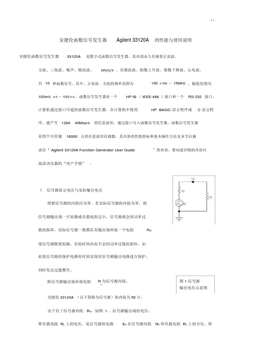
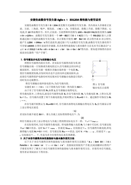
⒈ 信号源显示电压与实际输出电压理想信号源的内阻应为零。
若实际信号源的内阻为零,则信号源输出端一旦短路或负载电阻过小,信号源就会因功率过载而损坏。
实际信号源一般都在其输出端串接一个电阻R s,使信号源既使短路,在短时间内也不会因功率过载而损坏,由此使信号源的保护电路有时间实现对信号源输出电路进行保护,同时发出过载警告。
称信号源输出端串接电阻R 为信号源内阻。
图 1 信号源s输出电压示意图安捷伦 33120A (以下简称为信号源)的内阻为50 Ω。
由于有了信号源内阻 R s,如图 1 ,信号源输出端的电压,即负载电阻 R L上的电压,是信号源的电源E s在信号源内阻R s和负载电阻 R L上的分压,即V o≠E s。
信号源内设置了两个负载电阻值,开机时默认为R LD =50 Ω,通过操作可修改为R LD →∞。
在信号源开机默认为R LD =50 Ω时,信号源内部的电压源输出的电压为E s,信号源显示屏上显示的电压是V DisplayRLD1Es( 1 )R s R LDE s2若实际负载不是50 Ω,那么负载上实际得到的电压V o为V o R L E s 1E s( 2)R s R L2即信号源显示屏上显示的电压与负载上得到的实际电压不一样,V o≠V Display。
亚历山大技术33220A函数 模拟波形生成器数据手册说明书
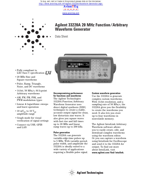
Agilent 33220A 20 MHz Function/ArbitraryWaveform GeneratorData Sheet•Fully compliant toLXI Class C specification•20 MHz Sine andSquare waveforms•Pulse, Ramp, Triangle,Noise, and DC waveforms•14-bit, 50 MSa/s, 64 k-pointArbitrary waveforms •AM, FM, PM, FSK, and PWM modulation types •Linear & logarithmic sweeps and burst operation•10 mV pp to 10 V ppamplitude range•Graph mode for visual verification of signal settings •Connect via USB, GPIBand LAN Uncompromising performance for functions andwaveformsThe Agilent Technologies 33220A Function/Arbitrary Waveform Generator uses direct digital synthesis (DDS) techniques to create a stable, accurate output signal for clean, low distortion sine waves. It also gives you square waves with fast rise and fall timesup to20 MHz and linearramp waves up to 200 kHz. Pulse generationThe 33220A can generate variable-edge-time pulses upto 5 MHz. With variable period, pulse width, and amplitude the 33220A is ideally suited to a wide variety of applications requiring a flexible pulse signal.Custom waveform generationUse the 33220A to generate complex custom waveforms. With 14-bit resolution, and a sampling rate of 50 MSa/s, the 33220A gives you the flexibility to create the waveforms you need. It also lets you storeup to four waveforms in nonvolatile memory.The Agilent IntuiLink Arbitrary Waveform software allowsyou to easily create, edit, and download complex waveforms using the waveform editor.Or you can capture a waveform using IntuiLink for Oscilloscope and send it to the 33220A for output. To find out more about IntuiLink, visit/find/intuilink./HP-Agilent-33220A-Waveform-Generator.aspxTo buy, sell, rent or trade-in this product please click on the link below:Measurement CharacteristicsEasy-to-use functionalityFront-panel operation of the 33220A is straight-forward and user friendly. You can access all major functions with a single key or two. The knob or numeric keypad can be used to adjust frequency, amplitude, offset, and other parameters. You can even enter voltage values directly in V pp, V rms, dBm, or as high and low levels. Timing parameters can be entered in Hertz (Hz) or seconds.Internal AM, FM, PM, FSK, and PWM modulation make it easy to modulate waveforms without the need for a separate modulation source. Linear and logarithmic sweeps are also built in, with sweep rates selec-table from 1 ms to 500 s. Burst mode operation allows for a user-selected number of cycles per period of time. GPIB, LAN, and USB interfaces are all standard, plus you get full programmability using SCPI commands.External frequency reference (Option 001)The 33220A external frequency reference lets you synchronize to an external 10 MHz clock,to another 33220A, or to an Agilent 33250A. Phase adjust-ments can be made from the front panel or via a computer interface, allowing precise phase calibration and adjustment.WaveformsStandard Sine, Square, Ramp,Triangle, Pulse,Noise, DCBuilt-in arbitrary Exponential rise,Exponential fall,Negative ramp,Sin(x)/x, CardiacWaveforms CharacteristicsSineFrequency Range 1 µHz to 20 MHzAmplitude Flatness[1], [2](relative to 1 kHz)< 100 kHz 0.1 dB100 kHz to 5 MHz 0.15 dB5 MHz to 20 MHz 0.3 dBHarmonic distortion[2], [3]< 1 V PP≥1 V PPDC to 20 kHz -70 dBc-70 dBc20 kHz to 100 kHz -65 dBc-60 dBc100 kHz to 1 MHz -50 dBc-45 dBc1 MHz to 20 MHz -40 dBc-35 dBcTotal harmonic distortion[2],[3]DC to 20 kHz 0.04%Spurious (non-harmonic)[2],[4]DC to 1 MHz -70 dBc1 MHz to 20 MHz -70 dBc + 6 dB/octavePhase noise(10 kHz offset)-115 dBc / Hz, typicalSquareFrequency range 1 µHz to 20 MHzRise/Fall time < 13 nsOvershoot <2%Variable duty cycle20% to 80% (to 10 MHz)40% to 60% (to 20 MHz)Asymmetry (@ 50% duty)1% of period + 5 nsJitter (RMS) 1 ns +100 ppm of periodRamp, TriangleFrequency range 1 µHz to 200 kHzLinearity < 0.1% of peak outputVariable Symmetry0.0% to 100.0%PulseFrequency range500 µHz to 5 MHzPulse width 20 ns minimum,(period ≤10s)10 ns resolutionVariable edge time < 13 ns to 100 nsOvershoot< 2%Jitter (RMS)300 ps +0.1 ppm of periodNoiseBandwidth 9 MHz typicalArbitraryFrequency range 1 µHz to 6 MHzWaveform length 2 to 64 k pointsAmplitude resolution 14 bits (including sign)Sample rate 50 MSa/sMin. Rise/Fall Time35 ns typicalLinearity < 0.1% of peak outputSettling Time < 250 ns to 0.5%of final valueJitter (RMS) 6 ns + 30 ppmNon-volatile memory four waveformsCommon CharacteristicsFrequencyAccuracy[5]±(10 ppm+ 3 pHz)in 90 days±(20 ppm+ 3 pHz)in 1 yearResolution 1 µHzAmplitudeRange 10 mV PP to10 V PP into 50 Ω20 mV PP to 20 V PPinto open circuitAccuracy[1],[2](at 1 kHz) ±1% of setting±1 mV PPUnits V PP, V rms, dBmResolution 4digitsDC OffsetRange (peak AC + DC)±5 V into 50 Ω±10 V into open circuitAccuracy[1],[2]±2% of offset setting±0.5% of amplitude±2 mVResolution 4 digitsMain OutputImpedance50 ΩtypicalIsolation 42Vpkmaximumto earthProtection Short-circuitprotected,overload automaticallydisables main outputExternal Frequency Reference (Option 001)Rear Panel InputLock Range 10 MHz ±500 HzLevel 100mV PP to 5 V PPImpedance 1kΩtypical,AC coupledLock Time < 2 secondsRear Panel OutputFrequency 10MH zLevel 632mV PP(0 dBm), typicalImpedance50 Ωtypical,AC coupled2Phase Offset Range + 360°to - 360°Resolution 0.001°Accuracy 20 nsModulationAMCarrier waveforms Sine, Square,Ramp, ArbSource Internal/External Internal modulation Sine, Square, Ramp,Triangle, Noise, Arb (2 mHz to 20 kHz)Depth 0.0% to 120.0%FMCarrier waveforms Sine, Square,Ramp, ArbSource Internal/ExternalInternal modulation Sine, Square, Ramp,Triangle, Noise, Arb (2 mHz to 20 kHz)Deviation DC to 10 MHz PMCarrier waveforms Sine, Square,Ramp, ArbSource Internal/ExternalInternal modulation Sine, Square, Ramp,Triangle, Noise, Arb (2 mHz to 20 kHz)Deviation 0.0 to 360.0 degrees PWM Carrier waveform Pulse Source Internal/External Internal modulation Sine, Square, Ramp, Triangle, Noise, Arb (2 mHz to 20 kHz)Deviation 0% to 100% of pulse widthFSKCarrier waveforms Sine, Square,Ramp, ArbSource Internal/External Internal modulation 50% duty cyclesquare (2 mHzto 100 kHz)External Modulation Input [6](for AM, FM, PM, PWM)Voltage range ±5 V full scaleInput impedance 5 k ΩtypicalBandwidth DC to 20 kHzSweep WaveformsSine, Square, Ramp, ArbT ype Linear or Logarithmic Direction Up or Down Sweep time 1 ms to 500 sTrigger Single, External,or InternalMarker falling edge of syncsignal (programmablefrequency)Burst [7]Waveforms Sine, Square, Ramp,Triangle, Pulse,Noise, Arb T ype Counted (1 to 50,000 cycles), Infinite, Gated Start/Stop Phase -360°to +360°Internal Period 1 µs to 500 s Gate Source External trigger Trigger source Single, Externalor Internal Trigger Characteristics Trigger input Input level TTL compatible Slope Rising or Falling, selectablePulse width > 100 ns Input impedance >10 k Ω, DC coupled Latency < 500 ns Jitter (rms) 6 ns (3.5 ns for pulse)Trigger outputLevel TTL compatible into ≥1 k ΩPulse width > 400 nsOutput Impedance 50 Ω, typicalMaximum rate 1 MHzFanout ≤4 Agilent 33220AsProgramming Times (typical)Configuration times USB LAN GPIB Function Change 111 ms 111 ms 111 ms Frequency Change 1.5 ms 2.7 ms 1.2 ms Amplitude Change 30 ms 30 ms 30 ms Select User Arb 124 ms 124 ms 123 ms Arb Download Times (binary transfer)USB LANGPIB64 k points 96.9 ms 191.7 ms 336.5 ms 16 k points 24.5 ms 48.4 ms 80.7 ms 4 k points7.3 ms14.6 ms 19.8 msGeneralPower Supply CAT II100 - 240 V @50/60 Hz (-5%, +10%)100 - 120 V @ 400 Hz (±10%)Power Consumption 50 VA max Operating Environment IEC 61010Pollution Degree 2Indoor Location Operating T emperature 0°C to 55°C Operating Humidity5% to 80% RH, non-condensingOperating Altitude Up to 3000 meters Storage T emperature -30°C to 70°C State Storage Memory Power off stateautomatically saved. Four user-configurable stored statesInterface USB, GPIB, andLAN standardLanguage SCPI - 1993,IEEE-488.2Dimensions (W x H x D)Bench top 261.1 mm x 103.8 mmx 303.2mmRack mount 212.8mm x 88.3mmx 272.3mmWeight 3.4 kg (7.5 lbs)Safety Designed to UL-1244, CSA 1010,EN61010EMC T ested to MIL-461C, EN55011,EN50082-1Vibration and Shock MIL-T-28800, T ype III,Class 5Acoustic Noise 30 dBa Warm-up Time 1 hour Warranty 1 year standardFootnotes[1]add 1/10th of output amplitude and offset spec per °C for operation outside the range of 18°C to 28°C [2]Autorange enabled [3]DC offset set to 0 V[4]spurious output at low amplitude is –75 dBm typical[5]add 1 ppm/°C average for operation outside the range of 18°C to 28°C [6]FSK uses trigger input (1 MHz maximum)[7]Sine and square waveforms above 6 MHz are allowed only with an “infinite” burst count3Measurement Characteristics (Continued)Ordering InformationAgilent 33220A20 MHz Function/ArbitraryWavefrom GeneratorAccessories includedOperating manual, service manual, quick reference guide, IntuiLink waveform editor software, test data, USB cable, and power cord (see language option). OptionsOpt. 001External timebase reference Opt. 0B0Delete manualOpt. 1CM Rackmount kit(also sold as Agilent 34190A) Opt. A6J ANSI Z540 calibrationOpt. AB0Taiwan: Chinese manual Opt. AB1Korea: Korean manualOpt. AB2China: Chinese manualOpt. ABA English: English manual Opt. ABD Germany: German manual Opt. ABF France: French manualOpt. ABJ Japan: Japanese manual Other Accessories34131A Carrying case34161A Accessory pouch34190A Rackmount kitFor more information on AgilentTechnologies’ products, applicationsor services, please contact your localAgilent office. The complete list isavailable at:/find/contactusPhone or FaxUnited States:(tel) 800 829 4444(fax) 800 829 4433Canada:(tel) 877 894 4414(fax) 800 746 4866China:(tel) 800 810 0189(fax) 800 820 2816Europe:(tel) 31 20 547 2111Japan:(tel) (81) 426 56 7832(fax) (81) 426 56 7840Korea:(tel) (080) 769 0800(fax) (080) 769 0900Latin America:(tel) (305) 269 7500Taiwan:(tel) 0800 047 866(fax) 0800 286 331Other Asia Pacific Countries:(tel) (65) 6375 8100(fax) (65) 6755 0042Email:*****************Contacts revised: 09/26/05Product specifications and descriptionsin this document subject to changewithout notice.© Agilent Technologies, Inc. 2006Printed in the USA, April 19, 20065988-8544ENAgilent Technologies’ Test and MeasurementSupport, Services, and AssistanceAgilent Technologies aims to maximize thevalue you receive, while minimizing yourrisk and problems. We strive to ensure thatyou get the test and measurement capabil-ities you paid for and obtain the supportyou need. Our extensive support resourcesand services can help you choose the rightAgilent products for your applications andapply them successfully.Every instrumentand system we sell has a global warranty.Two concepts underlie Agilent’s overallsupport policy: “Our Promise” and “YourAdvantage.”Our PromiseOur Promise means your Agilent test andmeasurement equipment will meet itsadvertised performance and functionality.When you are choosing new equipment,we will help you with product information,including realistic performance specifica-tions and practical recommendations fromexperienced test engineers. When youreceive your new Agilent equipment, wecan help verify that it works properly andhelp with initial product operation.Your AdvantageYour Advantage means that Agilent offersa wide range of additional expert test andmeasurement services, which you canpurchase according to your unique technicaland business needs. Solve problemsefficiently and gain a competitive edgeby contracting with us for calibration,extra-cost upgrades, out-of-warrantyrepairs, and on-site education and training,as well as design, system integration,project management, and other professionalengineering services. Experienced Agilent engi-neers and technicians worldwide can help youmaximize your productivity, optimize the returnon investment of your Agilent instruments andsystems, and obtain dependable measurementaccuracy for the life of those products.Agilent Email Updates/find/emailupdatesGet the latest information on the products andapplications you select.Agilent Direct/find/agilentdirectQuickly choose and use your test equipmentsolutions with confidence.Agilent Open/find/openAgilent Open simplifies the process of connectingand programming test systems to help engineersdesign, validate and manufacture electronic prod-ucts. Agilent offers open connectivity for a broadrange of system-ready instruments, open industrysoftware, PC-standard I/O and global support,which are combined to more easily integrate testsystem development.Agilent Technologies。
基于FPGA的实用多功能信号发生器的设计与制作

基于FPGA的实用多功能信号发生器的设计与制作基于FPGA的实用多功能信号发生器的设计与制作摘要多功能信号发生器已成为现代测试领域应用最为广泛的通用仪器之一,代表了信号源的发展方向。
直接数字频率合成(DDS)是二十世纪七十年代初提出的一种全数字的频率合成技术,其查表合成波形的方法可以满足产生任意波形的要求。
由于现场可编程门阵列(FPGA)具有高集成度、高速度、可实现大容量存储器功能的特性,能有效地实现DDS技术,极大的提高函数发生器的性能,降低生产成本。
本文首先介绍了函数信号发生器的研究背景和DDS的理论。
然后详尽地叙述了利用Verilog HDL描述DDS模块的设计过程,以及设计过程中应注意的问题。
文中详细地介绍了多种信号的发生理论、实现方法、实现过程、部分Verilog HDL代码以及利用Modelsim仿真的结果。
文中还介绍了Altera公司的DE2多媒体开发平台的部分功能及使用,并最终利用DE2平台完成了多功能信号发生器的大部分功能。
包括由LCD显示和按键输入构成的人机界面和多种信号的发生。
数字模拟转换器是BURR-BROWN 公司生产的DAC902。
该信号发生器能输出8种不同的信号,并且能对输出信号的频率、相位以及调制信号的频率进行修改设定。
关键词:信号发生器;DDS;FPGA;DE2Practical FPGA-based multi function signal generatordesign and productionAbstractMulti function signal generator has become the most widely used in modern testing field of general instrument, and has represented one of the development direction of the source. Direct digital frequency synthesis (DDS) is a totaly digital frequency synthesis technology, which been put forward in the early 1970s. Using a look-up table method to synthetic waveform, it can satisfy any requirement of waveform produce. Due to the field programmable gates array (FPGA) with high integrity, high speed, and large storage properties, it can realize the DDS technology effectively, increase signal generator’s performance and reduce production costs.Firstly, this article introduced the function signal generator of the research background and DDS theory. Then, it described how to design a DDS module by Verilog HDL, and introduced various signal occurs theory, method and the implementation process, Verilog HDL code and simulation results.This paper also introduces the function of DE2 multimedia development platform, and completed most of the functions of multi-function signal generator on DE2 platform finally. Including the occurrence of multiple signal and the man-machine interface which composed by LCD display and key input. Digital-to-analog converters is DAC902, which produced by company BURR-BROWN.This signal generator can output eight different kinds of signals, and the frequency of the output signal, phase and modulation frequency signal also can be modifyed.Key Words: Signal generator; DDS; FPGA; DE2目录论文总页数:34页1 引言 (1)1.1课题背景 (1)1.2国内外波形发生器的发展现状 (1)1.3本文研究的主要内容 (2)2 信号发生器原理 (2)2.1直接数字频率合成技术的基本原理 (2)2.2相位偏移控制 (3)2.3多种信号的发生 (3)2.3.1方波的发生 (3)2.3.2三角波发生 (4)2.2.3锯齿波发生 (4)2.3.4 PWM信号发生 (4)2.3.5 SPWM信号发生 (5)2.3.6 AM信号发生 (5)2.3.7 FM信号发生 (6)2.4DDS的特点 (7)2.4.1 DDS 的优点 (7)2.4.2 DDS 系统的缺点 (7)3 系统整体设计 (8)3.1硬件部分 (8)3.1.1 DE2实验板 (8)3.1.2 LCD模块 (9)3.1.2 DAC902 (11)3.2基于VERILOG的FPGA设计 (12)3.3软件工具 (12)3.3.1 Modelsim (12)3.3.2 Quartus (12)3.4系统设计 (13)3.4.1 系统初始化模块 (13)3.4.2按键模块和LCD模块 (13)3.4.3 RAM模块 (14)3.4.4数据转换模块 (15)3.4.5 DAC驱动模块 (15)3.4.6系统的运行 (15)4 VERILOG HDL代码实现与仿真 (15)4.1信号发生器模块 (15)4.1.1频率控制字和相位累加器 (15)4.1.2 相位偏移控制 (16)4.1.3正弦波发生模块 (17)4.1.4 方波发生模块 (17)4.1.5 三角波发生模块 (18)4.1.6 锯齿波发生模块 (18)4.1.7 PWM信号发生模块 (19)4.1.8 SPWM信号发生模块 (19)4.1.9 AM信号发生模块 (20)4.1.10 FM信号发生模块 (21)4.2按键输入模块 (22)4.3LCD显示模块 (23)4.4RAM模块 (24)4.5数据转换模块 (25)5 系统测试 (26)5.1控制及显示部分测试 (27)5.2输出频率测试 (27)5.3信号发生测试 (28)5.3.1 正弦波、方波、三角波、锯齿波测试 (28)5.3.2 PWM信号测试 (29)5.3.3 SPWM信号测试 (29)5.3.4 AM信号测试 (29)5.3.5 FM信号测试 (30)结论 (31)参考文献 (32)致谢...................................................... 错误!未定义书签。
单片机波形发生器
前言波形发生器是能够产生大量的标准信号和用户定义信号,并保证高精度、高稳定性、可重复性和易操作性的电子仪器。
函数波形发生器具有连续的相位变换、和频率稳定性等优点,不仅可以模拟各种复杂信号,还可对频率、幅值、相移、波形进行动态、及时的控制,并能够与其它仪器进行通讯,组成自动测试系统,因此被广泛用于自动控制系统、震动激励、通讯和仪器仪表领域。
在 70 年代前,信号发生器主要有两类:正弦波和脉冲波,而函数发生器介于两类之间,能够提供正弦波、余弦波、方波、三角波、上弦波等几种常用标准波形,产生其它波形时,需要采用较复杂的电路和机电结合的方法。
这个时期的波形发生器多采用模拟电子技术,而且模拟器件构成的电路存在着尺寸大、价格贵、功耗大等缺点,并且要产生较为复杂的信号波形,则电路结构非常复杂。
同时,主要表现为两个突出问题,一是通过电位器的调节来实现输出频率的调节,因此很难将频率调到某一固定值;二是脉冲的占空比不可调节。
在 70 年代后,微处理器的出现,可以利用处理器、A/D/和 D/A,硬件和软件使波形发生器的功能扩大,产生更加复杂的波形。
这时期的波形发生器多以软件为主,实质是采用微处理器对 DAC的程序控制,就可以得到各种简单波形。
90 年代末,出现几种真正高性能、高价格的函数发生器、但是HP公司推出了型号为 HP770S的信号模拟装置系统,它由 HP8770A任意波形数字化和HP1776A波形发生软件组成。
HP8770A实际上也只能产生8 中波形,而且价格昂贵。
不久以后,Analogic公司推出了型号为 Data-2020的多波形合成器,Lecroy 公司生产的型号为9100 的任意波形发生器等。
到了二十一世纪,随着集成电路技术的高速发展,出现了多种工作频率可过GHz 的DDS 芯片,同时也推动了函数波形发生器的发展,2003 年,Agilent的产品 33220A能够产生17种波形,最高频率可达到 20M,2005 年的产品N6030A 能够产生高达 500MHz的频率,采样的频率可达 1.25GHz。
33220a任意波形发生器校准手册

文章标题:深度解读:33220A任意波形发生器校准手册1. 引言在现代电子技术领域,波形发生器作为一种常见的测试设备,在各种电子设备的研发和生产中扮演着至关重要的角色。
而在波形发生器中,33220A任意波形发生器以其高精度、灵活性和广泛的应用领域而备受青睐。
然而,一台高质量的波形发生器离不开准确的校准,因此本文将从深度和广度的角度,解读33220A任意波形发生器的校准手册,以期帮助读者更全面地了解和掌握这一重要的技术。
2. 33220A任意波形发生器简介33220A任意波形发生器作为一款常见的精密仪器,具有多种波形的发生能力,同时还具备高精度和灵活性的特点。
它广泛应用于频率响应测试、传感器模拟、通信系统测试等领域,为工程师和科研人员提供了便捷的测试手段。
然而,要保证其输出信号的准确性和稳定性,则需要进行准确的校准工作。
3. 校准手册解读校准手册作为保证设备准确性和稳定性的指导文档,对于33220A任意波形发生器而言尤为重要。
在校准手册中,通常包含设备的基本信息、校准原理、校准方法、校准步骤和注意事项等内容。
3.1 设备基本信息在校准手册中,首先会对33220A任意波形发生器的基本信息进行介绍,包括设备型号、生产厂家、出厂日期、技术规格等。
这些信息对于理解设备的特性和性能非常重要,也为后续的校准工作提供了基础支持。
3.2 校准原理校准原理部分将介绍33220A任意波形发生器的工作原理、内部结构和关键元器件,以及输出信号的稳定性和准确性的保证机制。
通过深入理解校准原理,可以更好地把握校准的关键技术和要点。
3.3 校准方法和步骤校准方法和步骤部分则是校准手册的核心内容,它包括对设备进行校准的具体操作流程、校准所需的标准设备和仪器,以及校准过程中需要注意的细节和技巧。
根据校准手册的指导,技术人员可以按照一定的步骤和方法,对设备进行准确的校准工作。
3.4 注意事项校准手册中通常会对在校准过程中需要特别注意的事项进行说明,比如环境条件、检验周期、维护保养等,这些内容对于设备的长期稳定性和可靠性有着重要的影响。
AFG2021任意波形 函数发生器 产品技术资料说明书

任意波形/函数发生器AFG2021产品技术资料主要特点和优点20 MHz正弦波、10 MHz方波和脉冲波,为大多数应用提供经济的解决方案250 MS/s采样率和14位垂直分辨率,提供同类最优秀的信号保真度直观的类似AFG3000的用户界面,缩短学习周期和客户产品开发周期4 × 128 kS内存和USB存储器扩展装置,存储用户自定义的任意波形标配USB主控端口/设备端口,选配GPIB和LAN接口,在成本和通用性之间实现最佳平衡多种运行模式和调制模式,覆盖大多数客户的作业要求菜单和联机帮助分为8种语言2U高度和半机架宽度,适合台式应用和机架安装应用ArbExpress免费软件,编辑和下载用户自定义波形变得异常简便SignalExpress免费软件,把多种泰克台式仪器组合成低成本自动测试解决方案应用电子测试和设计传感器仿真教育和培训功能测试系统集成产品技术资料2 杰出的性能,经济的价格目前几乎所有消费品都带有电路或器件,要求输入特定电子信号,以便产品正确运行。
这些信号既可以是简单的音频频率或时钟信号,也可以是比较复杂的信号,如碰撞过程中安全气囊传感器发出的串行数据流或信号。
由于提供了20 MHz 带宽、14位分辨率和250 MS/s 采样率,AFG2021任意函数发生器能够以入门级价格,生成简单的信号和复杂的信号。
由于其12种标准波形、调制功能和内置噪声发生器,您可以迅速创建所需信号,全面测试自己的设计。
传承AFG3000直观的用户界面AFG3000系列任意波形/函数发生器创新的简便易用特点首先体现在AF2021的构件上,其可以迅速进入设置和运行特性。
此外,AFG3000客户可以简便地迁移到新的AFG2021上,而不必学习新的用户界面。
3.5英寸彩色TFT 屏幕以图形格式和文本格式显示相关参数,简便地查看波形信息,用户可以对设置全面树立信心,把重点放在手边的任务上。
前面板上的快捷按钮和旋转旋钮可以用最少的工作和时间进入最常用的功能和设置。
SCPI程控指令学习实验指导书
STATus、SYSTem、TEST、TRACe|DATA、TRIGger、UNIT 和 VXI 等 23 个子系 统命令集。
利用 Agilent Connection Expert 根据仪器 IP 配置仪器后,主控机通过 LXI 总线发送 SCPI 命令控制仪器,并在用户界面上显示程控命令和结果。
自动设置视频带 宽 设置中心频率 根 据 Span 自 动 设置中心频率 设置中心频率步 进 设置频率 span 设置起始频率 设置终止频率 设 置 ACP 测 量 平均扫描次数 设 置 ACP 测 量 平均模式 设置计算主信道 功率的积分带宽 设置信道功率测 量平均扫描次数 设置信道功率测 量平均模式 设置计算信道功 率的积分带宽 CA 自动定标 LC 关闭所有的标记 ul 连续峰值搜索开 at 关
四. 实验原理
SCPI 的目标是缩短自动测试设备(ATE,Automatic Test Equipment)程序开 发时间。SCPI 通过为仪器控制和数据使用提供一致的编程环境来达成这一目标。 所有的 SCPI 仪器都使用定义好的程控消息、仪器响应和数据格式来实现兼容的 编程环境。
SCPI 提供几种不同层次的仪器控制,简单的测量命令为用户提供容易、快 速的 SCPI 仪器控制,与此同时,更详细的命令则可以用于提供传统仪器控制。
过冲测量 周期测量 上升时间测量 平均值测量 最大值测量 最小值测量 峰峰值测量 波 波形前缀 形 波形样点数 获 波形数据来源 取 波形数据格式 获取波形数据 状 管理状态报告 态 使能 管 读取状态报告 理 管理标准事件 寄存器 读取标准事件 寄存器 设置测量完成 状态报告
功能 系 识别 统 自检 功 复位 能 清除
实验一 可程控仪器标准代码(SCPI)学习
安捷伦函数信号发生器Agilent 33120A的性能与使用说明
安捷伦函数信号发生器Agile nt 33120A 得性能与使用说明安捷伦函数信号发生器33120A 就是数字式函数信号发生器。
其内部永久存储着正弦波、方波、三角波、噪声、锯齿波、sin(x)/x 、负锯齿波、指数上升波、指数下降波、心电波,共10种函数信号。
其中,正弦波、方波得频率范围为100μHz-15MHz,幅值范围为100mV P -P -10V P-P 。
函数信号发生器有一个HP -IB(I EEE-488)接口与一个RS-232接口,计算机通过接口可遥控函数信号发生器,在计算机中使用HP BA SIC 语言程序或C 语言程序,能产生12bit 40Msa /s 得任意波形,通过接口写入函数信号发生器,函数信号发生器有四个可存储16000点得任意波形存储器。
其具体得性能指标与基本操作方法见本节后摘录自“Agi le nt 33120A Fu ncti on Ge ne rator Us er Gu ide ”得内容。
要知道详细得内容应阅读该仪器得“用户手册”。
⒈ 信号源显示电压与实际输出电压理想信号源得内阻应为零。
若实际信号源得内阻为零,则 信号源输出端一旦短路或负载电阻过小,信号源就会因功率过 载而损坏。
实际信号源一般都在其输出端串接一个电阻R s , 使信号源既使短路,在短时间内也不会因功率过载而损坏,由此使信号源得保护电路有时间实现对信号源输出电路进行保护, 同时发出过载警告。
称信号源输出端串接电阻Rs 为信号源内阻。
安捷伦33120A(以下简称为信号源)得内阻为50Ω。
由于有了信号源内阻R s ,如图1,信号源输出端得电压,即负载电阻RL上得电压,就是信号源得电源E s 在信号源内阻R s 与负载电阻R L上得分压,即V o ≠Es 。
信号源内设置了两个负载电阻值,开机时默认为R LD =50Ω,通过操作可修改为R L D→∞。
在信号源开机默认为R LD =50Ω时,信号源内部得电压源输出得电压为E s ,信号源显示屏上显示得电压就是(1)若实际负载不就是50Ω,那么负载上实际得到得电压Vo为(2)即信号源显示屏上显示得电压与负载上得到得实际电压不一样,Vo ≠VDispl ay 。
33210A函数和任意波形发生器用户指南
3 选择所需的单位。 按对应于所需单位的软键。在您选择单位时,函数发生器以显示的振幅输出 波形 (如果启用输出)。在本例中,按 mVRMS。
注意:您也可以使用旋钮和光标键输入所需的值。
18
第 1 章 快速入门 设置输出振幅
1
您可以非常容易地将显示的振幅从一个单位转换到另一个单位。例如,下列 步骤说明如何将振幅从 Vrms 转换到 Vpp。
3 外部调制输入端子 4 输入:外部触发/脉冲串门控
输出:触发输出
5 USB 接口连接器 6 LAN 接口连接器 7 GPIB 接口连接器 8 机箱接地
使用
菜单:
• 选择 GPIB 地址 (参见第 2 章)。
• 设置 LAN 接口的网络参数 (参见第 2 章)。
• 显示当前网络参数 (参见第 2 章)。
• Keysight Automation-Ready CD (Keysight IO Libraries Suite)。
• USB 2.0 电缆。
注意: Keysight 33210A Product Reference CD 上提供了 33210A 产品的所有 文档,通过网址 /find/33210A 也可以获得这些文档。另外 还可以付费购买印刷版 (硬拷贝)手册。
注意:只有当安装了选件 001 (外部时基参考)时,才存在有外部和内部 10 MHz 参考端子 (上图中的 1 和 2)。否则,这些连接器的插孔是被封住的。
为防止电击,必须将电源线接地。如果只有两触点电源插座,则应将仪器的 机箱接地螺钉 (参见上图)连接到良好的接地线路中。
6
本书内容
快速入门 第 1 章帮助您将函数发生器准备就绪并熟悉一些前面板特性。 前面板菜单操作 第 2 章为您介绍了前面板菜单并对函数发生器的一些菜单功 能进行了说明。 特性和函数 第 3 章提供了有关函数发生器功能和操作的详细说明。无论是从 前面板或是通过远程接口操作函数发生器,您都可以从本章找到有用信息。 远程接口参考资料 第 4 章提供了帮助您通过远程接口对函数发生器进行编程 的参考信息。 错误消息 第 5 章列出了在使用函数发生器时可能出现的错误消息。每条错误 消息都提供了帮助您诊断和解决问题的信息。 应用程序 第 6 章包含一些远程接口应用程序,用来帮助您开发自己的应用程序。 教程 第 7 章讨论了信号发生和调制技术的基本原理。 技术参数 第 8 章列出了函数发生器的技术参数。
安捷伦函数信号发生器Agilent 33120A的性能与使用说明
安捷伦函数信号发生器Agilent 33120A 的性能与使用说明安捷伦函数信号发生器33120A 是数字式函数信号发生器。
其内部永久存储着正弦波、方波、三角波、噪声、锯齿波、sin(x)/x 、负锯齿波、指数上升波、指数下降波、心电波,共10种函数信号。
其中,正弦波、方波的频率范围为100μHz -15MHz ,幅值范围为100mV P-P -10V P-P 。
函数信号发生器有一个HP-IB (IEEE-488)接口和一个RS-232接口,计算机通过接口可遥控函数信号发生器,在计算机中使用HP BASIC 语言程序或C 语言程序,能产生12bit 40Msa/s 的任意波形,通过接口写入函数信号发生器,函数信号发生器有四个可存储16000点的任意波形存储器。
其具体的性能指标和基本操作方法见本节后摘录自“Agilent 33120A Function Generator User Guide ”的内容。
要知道详细的内容应阅读该仪器的“用户手册”。
⒈ 信号源显示电压与实际输出电压理想信号源的内阻应为零。
若实际信号源的内阻为零,则 信号源输出端一旦短路或负载电阻过小,信号源就会因功率过 载而损坏。
实际信号源一般都在其输出端串接一个电阻R s , 使信号源既使短路,在短时间内也不会因功率过载而损坏,由 此使信号源的保护电路有时间实现对信号源输出电路进行保护, 同时发出过载警告。
称信号源输出端串接电阻R s 为信号源内阻。
安捷伦33120A (以下简称为信号源)的内阻为50Ω。
由于有了信号源内阻R s ,如图1,信号源输出端的电压,即负载电阻R L 上的电压,是信号源的电源E s 在信号源内阻R s 和负载电阻R L 上的分压,即V o ≠E s 。
信号源内设置了两个负载电阻值,开机时默认为R LD =50Ω,通过操作可修改为R LD →∞。
在信号源开机默认为R LD =50Ω时,信号源内部的电压源输出的电压为E s ,信号源显示屏上显示的电压是s s LD s LD Display E 21E R R R V =+=(1)若实际负载不是50Ω,那么负载上实际得到的电压V o 为s s L s L o E 21E R R R V ≠+=(2)即信号源显示屏上显示的电压与负载上得到的实际电压不一样,V o ≠V Display 。
Agilent 33250A功能 模拟波形生成器数据手册说明书
Agilent 33250A Function/Arbitrary Waveform GeneratorData Sheet• 80 MHz sine and square wave outputs • Sine, square, ramp, noise and other waveforms• 50 MHz pulse waveforms with variable rise/fall times• 12-bit, 200 MSa/s, 64K-point deep arbi-trary waveformStandard WaveformsThe Agilent Technologies 33250A Function/Arbitrary Waveform Generator uses direct digital-synthesis techniques to create a sta-ble, accurate output on all waveforms, down to 1 µHz frequency resolution. The benefits are apparent in every signal you produce, from the sine wave frequency accuracy to the fast rise/fall times of square waves, to the ramp linearity.Front-panel operation of the 33250A is straightforward and user friendly. The knob or numeric keypad can be used to adjust fre-quency, amplitude and offset. You can even enter voltage values directly in Vpp, Vrms, dBm, or high/low levels. Timing parameters can be entered in hertz (Hz) or seconds. Custom Waveform GenerationWhy settle for a basic function generator when you can get arbitrary waveforms at no extra cost? With the 33250A, you can generate arbitrary waveforms with 12-bit vertical resolution, 64K memory depth, and a sample rate of 200 MSa/s. You can also store up to four 64K-deep arbitrary waveforms in non-volatile memory with user-defined names to help you find the right waveform when you need it most.The included Agilent IntuiLink software allows you to easily create, edit, and down-load complex waveforms using the IntuiLink Arbitrary Waveform Editor. Or you can capture a waveform using IntuiLink oscilloscope or DMM and send it to the 33250A for output. For programmers, ActiveX components can be used to control the instrument using SCPI commands. IntuiLink provides the tools to easily create, download, and man-age waveforms for your 33250A. To find out more about IntuiLink, visit /find/intuilink. Pulse GenerationThe 33250A can generate simple pulses up to 50 MHz. With variable edge time, pulse width and voltage level, the 33250A is ideally suited to a wide variety of pulse applications.Built-in VersatilityAM, FM and FSK capabilities make it easy to modulate waveforms with or without a separate source. Linear or logarith-mic sweeps can be performed with a programmable frequency marker signal. Programmable burst count and gating allow you to further customize your signal.For system applications, both GPIB and RS-232 interfaces are standard, and support full programmability using SCPI commands.Color Graphical DisplayThe unique design of the 33250A combines a low-profile instrument with the benefits of a color graphical display. Now you can display multiple waveform parameters at the same time. The graphical interface also allows you to modify arbitrary waveforms quickly and easily.Timebase Stability and Clock Reference The 33250A TCXO timebase gives you frequency accuracy of 2 ppm for your most demanding applications. The external clock reference input/output lets you synchronize to an external 10 MHz clock, to another 33250A, or to another Agilent 332XXA Function/Arbitrary Wafeform Generator. Phase adjustments can be made from the front panel or via a computer interface, allowing precise phase calibration and adjustment.19812Product specifications and descriptions in this document subject to change without notice. © Agilent Technologies, Inc. 2009Printed in USA May 5, 20095968-8807ENOrdering InformationAgilent 33250A80 MHz Function/Arbitrary Wavefrom GeneratorAccessories includedOperating manual, service manual,quick reference guide, IntuiLink waveform editor software, test data, RS-232 cable, and power cord (see language option).OptionsOpt. 0B0 Delete manual Opt. 1CM Rackmount kit (also sold as Agilent 34190A) Opt. A6J ANSI Z540 calibration Opt. AB0 Taiwan: Chinese manual Opt. AB1 Korea: Korean manual Opt. AB2 China: Chinese manual Opt. ABA English: English manual Opt. ABD Germany: German manual Opt. ABF France: French manual Opt. ABJ Japan: Japanese manual Other Accessories 34131A Carrying case 34161A Accessory pouch 34190A Rackmount kit**For racking two 33250As side-by-side, order thefollowing items: Lock-link kit (p/n 5061-9694), Flange kit (p/n 5063-9212)Remove all doubtOur repair and calibration services will get your equipment back to you, performing like new, when prom-ised. You will get full value out of your Agilent equipment through-out its lifetime. Your equipment will be serviced by Agilent-trained technicians using the latest factory calibration procedures, automated repair diagnostics and genuine parts. You will always have the utmost confidence in your measurements. Agilent offers a wide range of ad-ditional expert test and measure-ment services for your equipment, including initial start-up assistance onsite education and training, as well as design, system integration, and project management.F or more information on repair and calibration services, go to:/find/removealldoubt/find/emailupdatesGet the latest information on theproducts and applications you select./find/agilentdirectQuickly choose and use your test equipment solutions with confidence.Agilent Email UpdatesAgilent DirectFor more information on Agilent Technologies’ products, applications or services, please contact your local Agi-lent office. The complete list is available at:/find/contactusAmericasCanada (877) 894-4414 Latin America 305 269 7500United States (800) 829-4444Asia Pacific Australia 1 800 629 485China800 810 0189Hong Kong 800 938 693India 1 800 112 929Japan 0120 (421) 345Korea 080 769 0800Malaysia 1 800 888 848Singapore 180****8100Taiwan 0800 047 866Thailand1 800 226 008Europe & Middle East Austria 01 36027 71571Belgium 32 (0) 2 404 93 40 Denmark 45 70 13 15 15Finland 358 (0) 10 855 2100France 0825 010 700**0.125 €/minuteGermany ************Ireland 1890 924 204Israel 972-3-9288-504/544Italy 39 02 92 60 8484Netherlands 31 (0) 20 547 2111Spain 34 (91) 631 3300Sweden 0200-88 22 55Switzerland 0800 80 53 53United Kingdom 44 (0) 118 9276201Other European Countries:/find/contactusRevised: March 24, 2009。
Agilent Technologies 33120A功能 随机波形生成器说明书
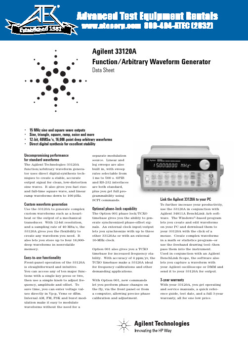
Uncompromising performance for standard waveformsThe Agilent Technologies 33120A function/arbitrary waveform genera-tor uses direct digital-synthesis tech-niques to create a stable, accurate output signal for clean, low-distortion sine waves. It also gives you fast rise-and fall-time square wave, and linear ramp waveforms down to 100µHz.Custom waveform generationUse the 33120A to generate complex custom waveforms such as a heart-beat or the output of a mechanical transducer. With 12-bit resolution,and a sampling rate of 40MSa/s, the 33120A gives you the flexibility to create any waveform you need. It also lets you store up to four 16,000-deep waveforms in nonvolatile memory.Easy-to-use functionalityFront-panel operation of the 33120A is straightforward and intuitive. You can access any of ten major func-tions with a single key press or two,then use a simple knob to adjust fre-quency, amplitude and offset. To save time, you can enter voltage val-ues directly in Vp-p, Vrms or dBm.Internal AM, FM, FSK and burst mod-ulation make it easy to modulate waveforms without the need for aseparate modulation source. Linear and log sweeps are also built in, with sweep rates selectable from 1ms to 500 s. GPIB and RS-232 interfaces are both standard, plus you get full pro-grammability using SCPI commands.Optional phase-lock capabilityThe Option 001 phase lock/TCXO timebase gives you the ability to gen-erate synchronized phase-offset sig-nals. An external clock input/output lets you synchronize with up to three other 33120As or with an external 10-MHz clock.Option 001 also gives you a TCXO timebase for increased frequency sta-bility. With accuracy of 4 ppm/yr, the TCXO timebase make a 33120A ideal for frequency calibrations and other demanding applications.With Option 001, new commands let you perform phase changes on the fly, via the front panel or from a computer, allowing precise phase calibration and adjustment.Link the Agilent 33120A to your PCTo further increase your productivity,use the 33120A in conjunction with Agilent 34811A BenchLink Arb soft-ware. The Windows®-based program lets you create and edit waveforms on your PC and download them to your 33120A with the click of amouse. Create complex waveforms in a math or statistics program—or use the freehand drawing tool—then pass them into the instrument. Used in conjunction with an Agilent BenchLink Scope, the software also lets you capture a waveform withyour Agilent oscilloscope or DMM and send it to your 33120A for output.3-year warrantyWith your 33120A, you get operating and service manuals, a quick refer-ence guide, test date, and a full 3-year warranty, all for one low price.• 15 MHz sine and square wave outputs• Sine, triangle, square, ramp, noise and more• 12-bit, 40MSa/s, 16,000-point deep arbitrary waveforms •Direct digital synthesis for excellent stabilityAgilent 33120AFunction/Arbitrary Waveform GeneratorData Sheet1981WaveformsStandard Sine, square, triangle, ramp,noise, sin(x)/x, exponentialrise exponential fall, cardiac,dc volts.ArbitraryWaveform length8 to 16,000 points Amplitude resolution12 bits (including sign) Sample rate40 MSa/sNon-volatile memory Four (4) 16,000 waveforms Frequency CharacteristicsSine100 µHz - 15 MHzSquare100 µHz - 15 MHz Triangle100 µHz - 100 kHzRamp100 µHz - 100 kHzWhite noise10 MHz bandwidth Resolution10 µHz or 10 digits Accuracy10 ppm in 90 days,20 ppm in 1 year,18°C - 28°CTemp. Coeff< 2 ppm/°CAging< 10 ppm/yr Sinewave Spectral PurityHarmonic distortiondc to 20 kHz-70 dBc20 kHz to 100 kHz-60 dBc100 kHz to 1 MHz-45 dBc1 MHz to 15 MHz-35 dBcSpurious (non-harmonic)DC to 1 MHz< -65 dBc1 MHz to 15 MHz< -65 dBc + 6 dB/octave Total harmonic distortionDC to 20 kHz<0.04%Phase noise<-55 dBc in a 30 kHz band Signal CharacteristicsSquarewaveRise/Fall time< 20 nsOvershoot4%Asymmetry1% + 5nsDuty cycle20% to 80% (to 5 MHz)40% to 60% (to 15 MHz) Triangle, Ramp, ArbRise/Fall time40 ns (typical)Linearity<0.1% of peak output Setting Time<250 ns to 0.5% offinal valueJitter<25ns Output CharacteristicsAmplitude (into 50Ω)50 mVpp - 10 Vpp [1]Accuracy (at 1 kHz)±1% of specified outputFlatness (sinewave relative to 1 kHz)< 100 kHz±1% (0.1 dB)100 kHz to 1 MHz±1.5% (0.15 dB)1 Mz to 15 MHz±2% (0.2 dB) Ampl ≥3Vrms±3.5% (0.3 dB) Ampl<3VrmsOutput Impedance50Ω(fixed)Offset (into 50Ω) [2]+ 5 Vpk ac + dcAccuracy±2% of setting + 2 mVResolution 3 digits, amplitude and off-setUnits Vpp, Vrms, dBmIsolation42 Vpk maximum to earthProtection Short circuit protected±15Vpk overdrive < 1 minuteModulationAMCarrier -3dB Freq.10 MHz (typical)Modulation any internal waveformincluding ArbFrequency10 mHz - 20 kHzDepth0% - 120%Source Internal/ExternalFMModulation any internal waveformincluding ArbFrequency10 mHz - 10 kHzDeviation10 mHz - 15 MHzSource Internal onlyFSKInternal rate10 mHz - 50 kHzFrequency Range10 mHz - 15 MHzSource Internal/External(1 MHz max.)BurstCarrier Freq. 5 MHz max.Count 1 to 50,000 cycles or infiniteStart Phase-360°to +360°Internal Rate10 mHz - 50 kHz ±1%Gate Source Internal/External GateTrigger Single, External orInternal RateSweepType Linear or LogarithmicDirection Up or DownStart F/Stop F10 mHz - 15 MHzSpeed 1 ms to 500 s ±0.1%Trigger Single, External, or InternalRear Panel InputsExt. AM Modulation±5 Vpk = 100% modulation5kΩinput resistanceExternal Trigger/TTL low trueFSK/Burst GateSystem Characteristics[3]Configuration Times[4]Function Change:[5]80 msFrequency Change:[5]30 msAmplitude Change:30 msOffset Change:10 msSelect User Arb:100 msModulation ParameterChange:<350 msArb Download Times over GPIBArb Length Binary ASCII Integer ASCII Real[6]16,000 points8 sec81 sec100 sec8,192 points 4 sec42 sec51 sec4,096 points 2.5 sec21 sec26 sec2,048 points 1.5 sec11 sec13 secArb Download Times over RS-232 at 9600 Baud:[7]Arb Length Binary ASCII Integer ASCII Real[8]16,000 points35 sec101 sec134 sec8,192 points18 sec52 sec69 sec4,096 points10 sec27 sec35 sec2,048 points 6 sec14 sec18 sec[1] 100 mVpp - 20 Vpp into open circuit[2] Offset ≤2x pk - pk amplitude[3] Times are typical. May vary based on controllerperformance[4] Time to change parameter and output the newsignal.[5] Modulation or sweep off[6] Times for 5-digit and 12-digit numbers[7] For 4800 baud, multiply the download times bytwo; For2400 baud, multiply the download timesby four, etc.[8] Time for 5-digit numbers; for 12-digit numbers,multiply the 5-digit numbers by two2Option 001 Phaselock/TCXO TimebaseTimebase AccuracySetability< 0.01 ppmStability±1 ppm 0°- 50°Aging< 2ppm in first 30 days(continuous operation)0.1 pm/month(after first 30 days)External Reference InputLock Range10 MHz ±50 HzLevel-10 dBm to + 15 dBm+25 dBm or 10 Vpp maxinputImpedance50Ω±2%, 42 Vpk isola-tion to earthLock Time< 2 secondsInternal Reference OutputFrequency10 MHzLevel> 1 Vpp into 50 ΩPhase OffsetRange+ 360°to - 360°Resolution0.001°Accuracy25 nsTrigger OutputLevel5V zero-going pulse Pulse Width> 2µs typicalFanout Capable of driving up tothree 33120As Ordering InformationAgilent 33120A Function/Arb GeneratorOpt. 001 Phase Lock/TCXO Timebase Option GeneralPower Supply110V/120V/220V/240V ±10%Power Line Frequency45 Hz to 66 Hz and 360 Hzto 440 HzPower Consumption50VA peak (28 W aveage) Operating Environment0°C to 55°CStorage Environment-40°C to 70°CState Storage Memory Power Off state automati-cally saved, 3 UserConfigurable StoredStatesInterface IEEE-488 and RS-232standardLanguage SCPI - 1993, IEEE-488.2 Dimensions (W x H x D)Bench top254.4mm x 103.6mm x374mmRack mount212.6mm x 88.5mm x348.3mmWeight 4 kg (8.8 lbs)Safety Designed to UL-1244, CSA 1010,EN61010EMC Tested to MIL-461C, EN55011,EN50082-1Vibration and Shock MIL-T-28800, Type III,Class5Acoustic Noise30 dBaWarm-up Time 1 hourWarranty 3 years standard3Ordering Information33120A Function/Arbitrary Waveform GeneratorAccessories includedOperating manual, service manual, quick reference guide, test data, and power cordOptionsOpt. 001Phase lock/TCXO timebaseOpt. 106BenchLink Arb software (34811A)Opt. 1CM Rack Mount Kit (34190A)*Opt. W50Additional 2-year warranty (5-year total)Opt. 910Extra manual setManual language options (please specify one)ABA US EnglishABD GermanABE SpanishABF FrenchABJ JapaneseABZ ItalianABO Taiwan ChineseAB1 KoreanAccessoriesAgilent 34161A Accessory pouchAgilent 34811A BenchLink Arb software*For racking two side-by-side, order both items belowLock-link Kit (P/N 5061-9694)Flange Kit (P/N 5063-9212)Windows®is a U.S. registered trademark of Microsoft Corporation.Agilent Technologies’ Test and Measurement Support, Services, and AssistanceAgilent Technologies aims to maximize the value you receive, while minimizing your risk and problems. We strive to ensure that you get the test and measure-ment capabilities you paid for and obtain the support you need. Our extensive sup-port resources and services can help you choose the right Agilent products for your applications and apply them successfully. Every instrument and system we sell has a global warranty. Support is availablefor at least five years beyond the produc-tion life of the product. Two concepts underlie Agilent’s overall support policy:“Our Promise” and “Your Advantage.”Our Promise“Our Promise” means your Agilent test and measurement equipment will meet its advertised performance and functionality. When you are choosing new equipment, we will help you with product informa-tion, including realistic performance spec-ifications and practical recommendations from experienced test engineers. When you use Agilent equipment, we can verify that it works properly, help with product operation, and provide basic measurement assistance for the use of specified capabil-ities, at no extra cost upon request. Many self-help tools are available.Your Advantage“Your Advantage” means that Agilent offers a wide range of additional expert test and measurement services, which you can purchase according to your unique technical and business needs. Solve prob-lems efficiently and gain a competitive edge by contracting with us for calibration,extra-cost upgrades, out-of-warranty repairs, and on-site education and training, as wellas design, system integration, project man-agement, and other professional services. Experienced Agilent engineers and techni-cians worldwide can help you maximize your productivity, optimize the return on investment of your Agilent instruments and systems, and obtain dependable measure-ment accuracy for the life of those products. Get assistance with all yourtest and measurement needs at:/find/assistOr check your local phone book for the Agilent office near you.Product specifications and descriptions inthis document subject to change without notice. Copyright © 1998, 2000 Agilent Technologies Printed in U.S.A. 4/005968-0125EN。
agilent_33522A_30M信号发生器

内部或外部, 或 33522A 的任意一个通道 脉冲宽度的 0% 至 100%, 0.01% 分辨率
在您对开发的产品进行设计验证 时,已生成信号的保真度至关重要。 保真度越高,验证就越可靠,您对所 开发的产品满足各项严格标准的信心 就越大。33500 系列函数和任意波形 发生器能够保证它产生的任何信号的 抖动均小于40 ps — 超过现有的函数 和任意波形发生器 10 倍以上。它具有 同类产品中最高的 16 位分辨率、小于 0.04% 的总谐波失真、高达 250 MSa/s (16 位) 的采样率、可选的高稳定性时 基和任意波形存储器扩展能力。借助 这些性价比非常出色的新型信号发生 器产品系列,您能够获得无与伦比的 信号保真度。
Agilent 30 MHz 函数和 任意波形发生器
技术资料
33521A 单通道函数和任意波形发生器 33522A 双通道函数和任意波形发生器
在同类产品中具有最低的 抖动和总谐波失真以及真正 的逐点生成任意波形能力, 可预防混叠 (alias-protected) 并提供出色的精度
实现更出色的精度和灵活性
通道输出、同步和调制输入的连接器外壳连接在一起, 但与仪器的机箱隔离。隔离连接器 外壳的最大允许电压是 ±42Vpk
50 Ω 用户可为每个通道选择一种设置 用户可定义的 V 最大值和 V 最小值限制 当出现过载时, 输出自动关闭 仪器将容忍不定期的接地短路 Cardiac、指数下降、指数上升、高斯脉冲、Haversine、Lorentz、D-Lorentz、负斜波、sinc
正弦波、方波、斜波、脉冲、三角波、高斯噪声、伪随机二进制序列 (PRBS)、直流 心率波、指数下降、指数上升、高斯脉冲、Haversine、Lorentz、D-Lorentz、负斜波、sinc 高达 1 M 点 (使用选件 002 可达到 16 M 点), 具有多段波形序列
33220A函数任意波形发生器详情资料,KEYSIGHT(是徳科技)信号发生器

33220A函数任意波形发生器详情资料,KEYSIGHT(是徳科技)信号发生器•20MHz正弦波和方波•脉冲、斜披、三角波,噪声和直流波形•14-bit,50MSa/s,64K点任意波形•AM、FM、PM、FSK和PWM凋制•线性和对数扫描及脉冲串模式•10mVpp至10Vpp幅苗范围•图形化界面可以对信号设置进行可视化验证•通过USB、GPIB和LAN连接性能优异的各种函数的波形Keysight(原Agilent) 33220A函数/任意波形发生器使用直接数字合成(DDS)技术,可生成稳定、精确、纯净和低失真的正弦输出信号。
它还能提供高达20MHz、具有快速上升和下降的方波,以及达200KHz的线性斜波。
脉冲沿信号33220A能产生达5MHz的可变沿时间脉冲。
33220A的脉冲还能具有可变的周期、脉冲宽度和幅度,对于需要灵活脉冲信号的各种应用是很理想的设备。
专用波形产生可用33220A产生复杂的专用波形。
33220A具有14bit分辨率和50MSa/s采样率,因此能够灵活地生成所需的波形。
非易失存储器中可保存4个波形。
有了Keysight(原Agilent) IntuiLink任意波形软件,您就可使用波形编辑器容易地生成、编辑和下载复杂的波形。
也可用IntuiLink捕获示波器波形,把它作为输出发送至33220A。
易于使用的功能33220A的前面板操作简捷而友好。
只需使用一、两个键,您就能访问所有主要功能。
旋钮或数字键可用来调节频率、幅度、偏置和其它参数。
您甚至还能直接输入Vpp、Vrms、dBm或高低电平值。
定时参数可以用Hertz(Hz)或秒为单位输入。
内部AM、FM、PM、FSK和PWM调制使仪器能容易地调制波形,而不需要单独的调制源。
线性和对数扫描也是内置功能,扫描速率可在1ms至500s范围内选择。
脉冲串模式允许用户选择每段时间的周期。
GPIB、LAN和USB接口均为标准配置,您还能获得SCPI命令的完全编程能力。
锁相放大器实验报告

ቤተ መጻሕፍቲ ባይዱ次实验的收获与体会
掌握了锁相放大器的基本原理和操作方法 学会了如何调整锁相放大器的参数以获得最佳性能 提高了实验动手能力和解决问题的能力 认识到团队合作在实验中的重要性,学会了如何与团队成员沟通和协作
对实验中遇到的问题和解决方案的反思与总结
遇到的问题:信号干扰、设备故障、操作失误等 解决方案:调整信号源、更换设备、规范操作等 反思:实验过程中需要注意的细节和可能出现的问题 总结:通过实验,提高了解决问题的能力和团队合作精神
调整锁相放大器参数,进行信号放大处理
调整锁相放大器参 数:设置合适的放 大倍数、相位差和 带宽
输入信号:选择合 适的信号源,如正 弦波、方波等
信号放大处理:将 输入信号通过锁相 放大器进行放大处 理
观察输出信号:使 用示波器等设备观 察输出信号的波形 和幅度,确保满足 实验要求
使用示波器和电脑采集和处理实验数据
Part Two
实验设备
锁相放大器
锁相放大器是一种用于测量微弱信号的电子设备。 锁相放大器的主要功能是提取信号中的频率和相位信息。 锁相放大器通常由一个参考信号和一个输入信号组成。 锁相放大器的性能指标包括灵敏度、动态范围、相位噪声等。
信号发生器
型号:Agilent 33220A 功能:产生正弦波、方波、三角波等信号 频率范围:1Hz-10MHz 精度:±0.01%
对实验教学的建议和改进意见
增加实验操作演示,帮助学生更好地理解和掌握实验步骤。 提供更多的实验案例,让学生通过实践锻炼解决问题的能力。 加强实验过程中的指导,及时发现并纠正学生的错误操作。 鼓励学生进行创新实验,培养学生的创新意识和实践能力。
对后续学习和实践的展望与计划
深入学习锁相放 大器的原理和应 用
函数任意波形发生器33250A技术资料

彩色图形显示
33250A采用独特的结构设计,它兼 有薄机箱和彩色图形显示的优点, 能同 时显示多个波形参数。该图形界面也使 您能便捷地调整任意波形。
时基稳定性和时钟基准
33250A TCXO 时基为最苛刻要求 的应用提供 2ppm 的年频率精度。外时 钟基准输入/输出可让仪器与外10MHz 时钟、另一台 3 3 2 5 0 A 或 A g i l e n t 33220A同步。也可从前面板或通过计算 机接口进行相位调节,以进行精密的相 位校准和调整。
选择用户任意波形 < 600ms,对于<16K 点
调制改变
< 200ms
任意波形下载时间 GPIB/RS-232(115Kbps) 任意波形长度 二进制 ASCII 整数 ASCII 实数
64K 点
48s 112s
186s
16K 点
12s
28s
44s
8K 点
6s
14s
22s
4K 点
3s
7s
11s
2K 点
0.01% + 525ps 0.1% + 75ps
20.0% - 80.0% 40.0% - 60.0% 50.0%,固定
20.00ns - 2000.0s 8.0ns - 1999.9s 5.00ns - 1.00ms <5% 100ppm + 50ps
斜波 线性度 对称性
<0.1% 峰输出 0.0% - 100.0%
2016全新精品资料全新公文范文全程指导写作独家原创18标准波形正弦波方波脉冲斜波噪声sinxx指数上升指数下降心律波dc电压任意波形波形长度1幅度分辨率12bit包括符号重复率1hz波器带宽50mhz非易失存储器个64k波形频率特性正弦波1hz80mhz方波1hz80mhz脉冲500hz50mhz任意波形1hz1mhz白噪声50mhz带宽分辨率1hz除脉冲为5个字精度12ppm180c280c3ppm00c550c2016全新精品资料全新公文范文全程指导写作独家原创18正弦波频谱纯度谐波失真3vpp1mhz60dbc55dbc1mhz5mhz57dbc45dbc5mhz80mhz37dbc30dbc总谐波失真dc20khz20mhz80mhz50dbc6dbc倍频程相位噪声30khz带10mhz方波2016全新精品资料全新公文范文全程指导写作独家原创18上升下降时间不对称性1周期1ns抖动rms20000s脉冲宽度80ns19999s可变沿时间500ns抖动rms100ppm50ps斜波线性度线性度稳定时间30ppm25ns输出特性幅度至50?10mvpp10vpp精度1khz10mvpp自动量程1设置1mvpp平坦度正弦波相对1khz自动量程高和低电平2016全新精品资料全新公文范文全程指导写作独家原创18分辨率01mv个字偏置至50?5vvpkacdc精度1设置2mv05幅度波形输出阻抗50?典型值固定10m?输出禁用隔离42vpk对地最大值保护短路保护过载自动禁用主输出am载波波形正弦波方波斜波和任意波形调制波形正弦波方波斜波噪声和任意波形调制频率2mhz20khz深度001200源内外fm载波波形正弦波方波斜波和任意波形调制波形正弦波方波斜波噪声和任意波形调制频率2mhz20khz峰变化dcfsk载波波形正弦波方波斜波和任意波形调制波形50占空比方波内部速率2mhz1mhz频率范2016全新精品资料全新公文范文全程指导写作独家原创18围1hz80mhz源内外外调制输入电压范围5v频率dc至20khz脉冲串波形正弦波方波斜波脉冲任意波形噪声频率1hz80mhz3脉冲串计数1000000次循环或无限开始停止相位36003600内部周期1ms500s闸门源外触发触发源单次手动触发内触发外触发触发延迟周期无限00ns85000s2016全新精品资料全新公文范文全程指导写作独家原创18扫描波形正弦波方波斜波任意波
labview通过USB控制agilent33220
Labview的仪器控制程序设计摘要LabVIEW(Laboratory Virtual instrument Engineering)是一种图形化的编程语言,它广泛地被工业界、学术界和研究实验室所接受,视为一个标准的数据采集和仪器控制软件。
通过USB接口直接连接PC和agilent33220任意波形发生器,运用labview来控制agilent33220,产生任意波形。
第一部分,通过labview实现了对指定波形如:直流波(DC),sin三角正弦函数波(sine),矩形波(square),三角波(triangle),斜波(ramp),脉冲(pulse),噪声(noise),SinX/X (sinc)等波形的频率(HZ,KHZ,MHZ),幅值(mV,V)的控制。
第二部分,对于任意波形。
首先,打开画图,手写随意画一个波形,保存为单色位图。
打开matlab,读取这张图,并转化为矩阵,编写一个简单的m程序,读取每列中0的高度。
并产生一个记录每列0高度的矩阵。
输出这个矩阵数据到txt文档。
其次,打开labview,读取txt,转化为矩阵。
输入给产生任意波形的元件,再输出到33220上,从而产生一个和手写波形一样的波形了。
关键词:labview ,agilent33220 ,matlabLabview instrument control programmingAbstractLabVIEW (Laboratory Virtual instrument Engineering) is a graphical programming language, it is widely in industry, academia and research laboratories accepted as a standard data acquisition and instrument control software.Directly connected to PC through USB interface, and agilent33220 arbitrary waveform generator, using labview to control the agilent33220, generate arbitrary waveforms.The first part, through labview achieve the specified waveform such as: DC wave (DC), sin triangular sine wave (sine), rectangular wave (square), triangle (triangle), ramp (ramp), pulse (pulse), noise (noise), SinX / X (sinc) such as the frequency of the waveform (HZ, KHZ, MHZ), amplitude (mV, V) control.The second part, for any waveform. First, open the drawing, handwriting free to draw a waveform, save for the monochrome bitmap. Open matlab, read this map, and into the matrix, write a simple m program to read the height of each column 0. And produce a record height of each column matrix 0. Output of the matrix data to the txt document.Second, open labview, read txt, into a matrix. Input device to generate arbitrary waveforms, and then output to 33,220, and to produce one and the same wave of the hand wave.Keywords: labview ,agilent33220 ,matlab目录摘要 (1)Abstract (2)第一章引言 (4)1.1 Labview概述 (4)1.1.1 虚拟仪器(VI) (4)1.1.2 labview软件 (4)第二章labview简介 (5)2.1 labview含义 (5)2.1.1虚拟仪器(VI)的概念 (5)2.1.2 labview的概念 (5)2.2 labview的特点 (6)2.3 Labview版本信息 (6)2.4 labview8.2下载 (6)第三章agilent 33220简介 (7)3.1技术资料 (7)3.2 33220A 的LabVIEW驱动程序 (7)第四章程序的编写 (8)4.1 单个波形 (8)4.2 多个波形 (10)4.3 任意波形 (13)4.4 任意波形的操作简化 (17)第五章结语 ........................................................................................... 错误!未定义书签。
- 1、下载文档前请自行甄别文档内容的完整性,平台不提供额外的编辑、内容补充、找答案等附加服务。
- 2、"仅部分预览"的文档,不可在线预览部分如存在完整性等问题,可反馈申请退款(可完整预览的文档不适用该条件!)。
- 3、如文档侵犯您的权益,请联系客服反馈,我们会尽快为您处理(人工客服工作时间:9:00-18:30)。
/find/emailupdates 得到您所选择的产品和应用的最新信息。
Agilent 测试和测量软件及连通性 Agilent 测试和测量软件及连通性产品、解决方案和开发网能使您容易地使用基于 PC 标
准的工具,把仪器接到计算机上,从而能集中关注您的任务,而不必为连接问题分心。要了 解更详细的情况,请访问:/find/connectivity。
正弦波,方波,斜波,任意波形 内部 / 外部 正弦波,方波,斜波,三角波,噪声,任意波形 (2mHz - 20kHz) 0.0°- 360.0°
2
PWM
载波波形
脉冲
源
内部 / 外部
内调制
正弦波,方波,斜波,三角波,噪声,任意波形
(2mHz - 20kHz)
偏移
0% - 100% 脉冲宽度
FSK
载波波形
不对称性(@50% 占空比) 1% 周期+ 5ns
抖动(RMS)
1ns + 100ppm 周期
斜波,三角波
频率范围 线性度
1µHz - 200kHz <0.1% 峰输出
可变对称性
0.0% - 100.0%
脉冲
频率范围 脉冲宽度
500µHz - 5MHz 20ns 最小
(周期≤ 10s)
10ns 分辨率
可变沿时间
< 13ns - 100ns
过冲
< 2%
抖动(RMS)
300ps + 0.1ppm 周期
噪声
带宽Βιβλιοθήκη 10MHz,典型值任意波形
频率范围
1µHz - 6MHz
波形长度
2 - 64K 点
幅度分辨率
14bit(包括符号)
采样率
50MSa/s
最小上升 / 下降时间 35ns,典型值
线性度
< 0.1% 峰输出
通用指标 电源
功耗 工作环境
工作温度 工作湿度 工作高度 存储温度 状态存储器
接口 语言 尺寸(W × H × D)
工作台 上架 重量 安全设计符合 EMC 测试符合 振动和冲击 声噪声 预热时间 保修期
CAT II 100 - 240V @ 50/60Hz(-5%, +10%) 100 - 120V @ 400Hz(± 10%) 50VA,最大值 IEC 1010 2 级污染 室内工作 0℃至 55℃ 5% 至 80% RH,不结水 3000m -30℃至 70℃ 关机时自动保存状态 保存 4 个用户配置状态 USB, GPIB, LAN 均为标准配置 SCPI - 1993, IEEE - 488.2
产生定制波形
用 33220A 产生复杂的定制信号。它有 14bit 分辨率 和 50MSa/s 采样率,可以灵活地建立所需波形的性。您 也可在非易失存储器中保存 4 个波形。在波形编辑器中 用Agilent Intuilink Arbitrary Waveform软件容易地建立、 编辑和下载复杂波形。或使用IntuiLink for Oscilloscope 捕获波形,之后将该波形把它发送到 33220A。要了解 有关 Intuilink 的详细情况,请访问:/ find/intuilink。
4位
直流偏置
量程(峰 AC+DC) 精度⑴⑵ 分辨率
±5V,至 50Ω ±10V,至开路 ±2% 偏置设置 ±0.5% 幅度 ±2mV 4位
主输出
阻抗
50Ω,典型值
隔离
42Vpk 最大,对地
保护
短路保护,过载自动禁止主输出
内频率参考
精度⑸
±10ppm,90 天
±20ppm,1 年
外频率参考(选件 001)
调整频率、幅度、偏置和其它参数。甚至能直接用 Vpp, Vrms ,dBm 或高低电平送入电压值。定时参数能以赫 兹(Hz)或秒送入。
可用内部AM,FM,PM,FSK和PWM调制容易地调制 波形,而不需要单独的调制源。线性和对数扫描也是内 置的,可选择 1ms 至 500s 的扫描率。突发模式允许用 户选择每周期时间的循环数。GPIB, LAN 和 USB 接口 均为标准配置,并有完全的 SCPI 命令编程能力。
3
安捷伦测试和测量技术支持、服务和协助 Agilent 公司的宗旨是使您获得最大效益,而同时将您的风险和问题减少到最低限度。我
们将努力确保您获得的测试和测量能力物有所值,并得到所需要的支持。我们广泛的支持和 服务能帮助您选择正确的 Agilent 产品,并在应用中获得成功。我们所销售的每一类仪器和系 统都提供全球保修服务。对于停产的产品,在 5 年内均可享受技术服务。“我们的承诺”和 “用户至上”这两个理念高度概括了 Agilent 公司的整个技术支持策略。 我们的承诺
后面板输入
锁定范围 电平 阻抗 锁定时间
10MHz ± 500Hz
100mV - 5V
pp
pp
1kΩ 典型值,交流耦合
< 2秒
后面板输出
频率
10MHz
电平
632MVpp (0 dBm), 典型值
阻抗
50Ω 典型值,交流耦合
相位偏置
范围
+360°至 -360°
分辨率
0.001°
精度
20ns
调制 AM
载波波形 源 内调制
外频率参考(选件 001)
易于使用的众多功能
33220A 有非常友好的用户操作前面板. 您可用一、 两个键容易地访问所有主要功能。用旋钮或数值键区
33220A 的外频率参考可用于与外 10MHz 时钟、其 它 33220A 或 Agilent 33250A 同步。也可从前面板或通 过计算机接口进行相位调整,从而进行精确的相位校准 或调整。
上海分公司 地址:上海市西藏中路 268 号
来福士广场办公楼 7 层 电话:(021) 23017688 传真:(021) 63403229 邮编:200001
稳定时间
< 250ns 至 0.5% 终值
抖动(RMS)
6ns + 30ppm
非易失存储器
4 个波形
公共特性
频率
分辨率
1µHz
幅度
量程
精度⑴⑵(1kHz) 单位 分辨率
10mVpp - 10Vpp,至 50Ω
20mVpp - 20Vpp,至开路
±1% 设置值 ±1mVpp
V ,V ,dBm
pp
rms
261.1mm × 103.8mm × 303.2mm 212.8mm × 88.3mm × 273.3mm 3.4kg UL-1244, CSA 1010, EN61010 MIL-461C, EN55011, EN50082-1 MIL-T-28800, III 类,5 级 30dBa 1 小时 1年
突波⑺ 波形 类型 起动 / 停止相位 内部周期 选通源 触发源
正弦波,方波,斜波,三角波,噪声,任意波形 计数(1 至 50,000 循环),无限,选通 -360°至 +360° 1µs - 500s 外触发 单次,外或内
触发特性 触发输入
输入电平 斜率 脉冲宽度 输入阻抗 反应时间 抖动(RMS) 触发输出 电平 脉冲宽度 输出阻抗 最大速率 扩展性
深度 FM
载波波形 源 内调制
偏移 PM
载波波形 源 内调制
偏移
正弦波,方波,斜波,任意波形 内部 / 外部 正弦波,方波,斜波,三角波,噪声,任意波形 (2mHz - 20kHz) 0.0% - 120.0%
正弦波,方波,斜波,任意波形 内部 / 外部 正弦波,方波,斜波,三角波,噪声,任意波形 (2mHz - 20kHz) DC - 10MHz
30ms
选择用户任意波形 124ms
任意波形下载时间(二进制传输)
USB
64K 点
96.9ms
16K 点
24.5ms
4K 点
7.3ms
LAN 111ms 2.7ms 30ms 124ms
LAN 191.7ms 48.4ms 14.6ms
GPIB 111ms 1.2ms 30ms 123ms
GPIB 336.5ms 80.7ms 19.8ms
DC - 1MHz
-70dBc
1MHz - 20MHz
-70dBc + 6dB/ 倍频程
相位噪声
(10kHz 偏置)
-115dBc/Hz,典型值
方波
频率范围 上升 / 下降时间
1µHz - 20MHz < 13ns
过冲
< 2%
可变占空比
20% - 80%(至 10MHz)
40% - 60%(至 20MHz)
波形 标准 内置任意波形
正弦波,方波,斜波,三角波,脉冲,噪声,直流 指数上升,指数下降,负斜波,Sin(x)/x,心律波
波形特性
正弦波
频率范围
1µHz 至 20MHz
幅度平坦度⑴⑵
(相对于 1kHz)
< 100kHz
0.1dB
100kHz - 5MHz
0.15dB
5MHz - 20MHz
0.3dB
TTL 兼容 上升或下降,可选 > 100ns > 10kΩ,直流耦合 < 500ns 6ns(3.5ns,对于脉冲)
TTL 兼容,至≥ 1kΩ > 400ns 50Ω,典型值 1MHz ≤ 4 Agilent 33220A
编程时间(典型值)
配置时间
USB
功能改变
111ms
频率改变
1.5ms
幅度改变
请通过Internet、电话、传真得到测试和测量帮助。 在线帮助:/find/assist 热线电话:800-810-0189