最新工业微型计算机55172
施乐1080说明书

TM1723 LCD驱动控制专用电路说明书
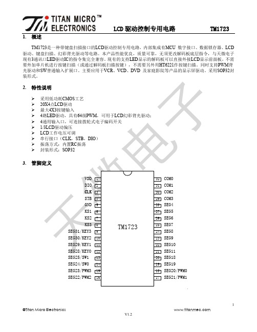
1.概述TM1723是一种带键盘扫描接口的LCD驱动控制专用电路,内部集成有MCU 数字接口、数据锁存器、LCD 驱动、键盘扫描、幻彩背光驱动等电路。
本产品性能优良,质量可靠,无须更改解码板底层指令,与天微电子现有3通讯口LED驱动IC的指令集完全兼容。
现有的支持LED显示的解码板可以直接外接LCD显示前面板,不需要外加单片机进行按键扫描(或通过解码板扫描按键),不需要另外用HT6221作按键扫描。
同时支持PWM背光驱动和SW普通输入扩展口。
主要应用于VCR、VCD、DVD 及家庭影院等产品的显示屏驱动。
采用SOP32封装形式。
2.443..4.▲注意:DIO在时▲SEGx/KEYx5.显示寄存器该寄存器存储通过串行接口从外部器件传送到TM1723 的数据,有效地址寄存器共11字节单元,分别与芯片SGE和COM管脚所接的LCD段位对应,分配如下图:写LCD显示数据的时候,按照从显示地址从低位到高位,从数据字节的低位到高位操作。
采用地址自动加一模式送数据时,00H、01H、06H~08H、0DH 地址数据可任意填充,建议填充数据0。
6.在传送的指令或数据保持有效)。
6.1. 显示模式设置工作模式设置好后,不允许在使用中切换工作模式。
6.2.6.3. 地址命令设置图(2)键扫数据储存地址如下所示,先发读键命令后,开始读取按键数据BYTE1—BYTE2字节,读数据从低位开始输出。
芯片KEY(0—3)和KS引脚对应的按键按下时,相对应的字节内的BIT位为1。
7.2.该寄存器存储通过串行接口从TM1723的读取数据,地址分配如下:▲注意与KS3三7.3.t=130us图(7)T、t 和IC工作的振荡频率有关,我公司TM1723经过多次完善,振荡频率不完全一致,测量参数仅仅提供参考,以实际测量为准。
8.端口控制寄存器8.1.PWM图(8)TM1723芯片+5V供电,用示波器观察到PWM口的波形,如图(9):8.2.以图(10)为例子介绍SW输入口的原理。
RICOH Aficio MP 1911 操作说明书
基本操作步骤 ............................................................................................. 19 从手送台复印 ............................................................................................. 20 复印机功能 ................................................................................................. 23
目录
版权和商标 ................................................................................................... 1 商标 ......................................................................................................................... 1
2. 放置原稿
原稿 ........................................................................................................... 17 推荐的原稿尺寸和重量 ....................................................................................... 17 图像缺失区域 ....................................................................................................... 17
NCStudio操作手册
维宏®数控系统NCSTUDIO V5.4软件使用手册目录升级纪录............................................................................................................................ I I 目录.. (I)1概述 (1)1.1软件特性 (1)2系统安装与连接 (3)2.1N CSTUDIO™的系统基本配置 (3)计算机主机 (3)操作系统 (3)2.2N CSTUDIO™系统的安装 (4)安装Ncstudio™软件 (5)安装Ncstudio™运动控制卡 (8)重新启动计算机 (8)2.3其他安装问题 (8)2.4卸载N CSTUDIO™系统 (9)2.5N CSTUDIO™控制卡与驱动系统的连接 (10)3NCSTUDIO™基本概念 (11)3.1操作模式与状态 (11)操作模式 (11)操作状态 (12)3.2机床坐标系 (13)机械坐标系 (13)工件坐标系 (13)4NCSTUDIO™操作界面 (15)4.1标题栏 (16)4.2菜单栏 (17)4.3工具栏 (18)4.4数控信息栏 (19)4.5状态栏 (19)4.6数控状态窗口 (19)加工状态和时间信息 (20)当前位置 (20)进给速度 (21)机床控制 (22)4.7自动操作窗口 (23)4.8手动操作窗口 (25)4.9加工轨迹窗口 (28)三维视图模式 (28)上下文菜单 (31)设置个性化参数 (31)4.10系统日志窗口 (32)4.11程序管理窗口 (33)4.12系统参数窗口 (34)加工参数 (35)厂商参数 (38)4.13程序编辑窗口 (41)4.14输入输出状态(I/O状态)窗口 (42)5NCSTUDIO™菜单系统 (44)5.1“文件”菜单 (44)打开并装载 (44)卸载 (45)新建加工程序 (46)打开并编辑 (46)编辑当前加工程序 (46)保存 (46)另存为 (46)关闭 (47)最近装载的加工程序 (47)最近编辑的加工程序 (47)退出 (47)5.2“编辑”菜单 (48)5.3“查看”菜单 (49)工具栏 (50)状态栏 (50)全屏 (50)显示加工程序行号 (51)跟踪加工程序当前行 (51)加工程序信息 (52)5.4“操作”菜单 (52)单步执行 (53)设置当前点为工件原点 (53)设置当前点工件坐标 (54)回工件原点 (54)开始 (55)暂停 (56)停止 (56)进入仿真模式并开始仿真 (56)高级开始 (57)断点继续 (57)执行加工指令 (58)微调 (61)对刀 (62)回机械原点 (62)复位 (63)5.5“机床”菜单 (64)5.6“窗口”菜单 (64)5.7“帮助”菜单 (65)6操作步骤 (66)6.1开机 (66)6.2机械复位(可选) (66)6.3载入加工程序 (66)6.4手动操作 (67)6.5确定工件原点 (67)6.6执行自动加工 (68)6.7直接定位功能 (69)7操作时的注意事项 (70)7.1多任务执行注意事项 (70)7.2回机械原点注意事项 (70)8最终用户软件许可协议 .................................................... 错误!未定义书签。
TPC7082S 说明书
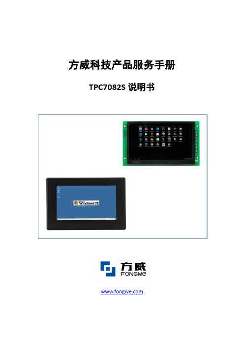
方威科技产品服务手册TPC7082S说明书TPC7082S,是一款以嵌入式低功耗ARM Cortex A8 CPU为核心(主频1 GHz)的高性能嵌入式一体化人机界面。
该产品设计采用了7英寸高亮度TFT真彩液晶屏(分辨率1024×600),电容式触摸屏,以及电磁屏蔽性好、美观超轻薄的金属外壳。
产品可运行安卓、WinCE 6.0、Linux等系统,并在安卓系统下可支持TeslaSCADA、mySCADA等国外的APP形式工业组态软件。
产品特性液晶屏:7″TFT真彩液晶屏,分辨率(1024×600)CPU主板:ARM Cortex A8,1GHz内存:工业级512MB DDR3存储设备:工业级512MB Flash电子盘(可扩SD卡)触摸屏:电容式触摸屏(支持多点触控)接口:2×RS232,2×RS485,1×CAN,2×USB,1×LAN,Audio In/Out其他功能:支持蜂鸣器和扬声器LCD规格产品规格显示类型:7″TFT真彩液晶屏结构:全封闭金属结构分辨率:1024×600 颜色:工业黑色亮度:350nit 安装:嵌入式对比率:500:1 电源:6~42V DC(12V时最大电流600mA)工作温度:-20°C 至+70°C 功率:5WLCD寿命:50,000小时总体尺寸:背光寿命:30,000小时前面板:机柜开孔:净重:应用环境相关软件工作温度:-20°C 至+70°C 操作系统:Android 4.1 \ WinCE 6.0 \ Linux \ 工作湿度:5%至90%@50°C Debian \ Angstrom储存温度:-30°C 至+80°C储存湿度:5%至90%@40°C 应用软件:可选用TeslaSCADA、mySCADA 振动:10至57Hz位移幅值0.075mm 等APP形式组态软件,或用户57至150Hz峰值加速度9.8m/s2自行开发软件冲击:峰值加速度150 m/s2冲击脉冲宽度:10ms,半正弦波电源说明如图所示,产品采用了宽电压输入(6~42V DC),总功率为5W左右。
河尔莱特-1670D型号微处理器系统分析仪技术数据说明书

Technical DataIdentifying the cause of problems in embedded microprocessor system designs can be difficult. The Hewlett-Packard 1670-series bench-top logic analyzers have the fea-tures to help the embedded system design team find hardware and soft-ware defects quickly.With 64K of acquisition memory (1M optional) the HP 1670-serieslogic analyzers are the first bench-top logic analyzers which display processor mnemonics and verify critical hardware timing relation-ships over a long period of time.With the standard Ethernet LAN interface, the software designer can now capture a real-time micropro-cessor trace and time-correlate it to source code in C++ or other high-level languages on a PC or worksta-tion. For time-correlation of source code, order the HP B3740A Software Analysis package.Logic Analyzer Key Specifications and Characteristics_______________________________________________________________________Model Number HP 1670D HP 1671D HP 1672D _______________________________________________________________________State and Timing 13610268Channels _______________________________________________________________________Timing Analysis Conventional: 125 MHz all channels, 250 MHz half channels_______________________________________________________________________State Analysis 100 MHz, all channels Speed _______________________________________________________________________State Clocks/444Qualifiers _______________________________________________________________________Memory Depth 64K per channel, 128K in timing half-channel mode per Channel (1M per channel optional memory,2M in timing half-channel mode)_______________________________________________________________________The combination of deep memory,large internal disk drive, and LAN make the HP 1670-series of bench-top logic analyzers especially well suited to solving your integrationproblems.•Mass storage is provided by an inter-nal hard drive which provides quick storage and retrieval of files.•The 3.5-inch high-density flexible disk drive supports both DOS and LIF formats.•The LAN interface enables access tothe logic analyzer files via FTP orNFS. Use X11 windows to control or view the logic analyzer on a PC or workstation. The LAN interfaceincludes both Ethertwist (10BASE-T)and ThinLan (10BASE 2) connectors.•Store data as ASCII files and screen images in TIFF , PCX, and EPS (encapsulated PostScript TM ) formats.•New graphical trigger macros make trigger setup easier.•Centronics, RS-232, HP-IB and LAN communication ports make connect-ing to other devices easier than ever.All of these come standard on all models of the HP 1670-series.•The HP 1670-series operating system includes System PerformanceAnalysis (SPA). SPA provides state histograms, state overview, and time interval analysis.•The HP E2450A Symbolic Download Utility is included with the HP 1670-series. This utility provides the capa-bility to extract symbolic information from popular object module formats.PostScript TM is a trademark of Adobe Systems Incorporated.Get to the root cause ofproblems quicklyHP 1670-Series General-Product Information_________________________ Human Interface_________________________ Front Panel A knob and keypadsmake up the front-panel human interface.Keys include control,menu, display naviga-tion, and alpha-numer-ic entry functions._________________________Mouse A DIN mouse is shippedas standard equipment.It provides full instru-ment control. Knobfunctionality is replicat-ed by holding down theright button and movingthe mouse left or right. _________________________Keyboard The logic analyzer canalso be operated usinga DIN keyboard. Orderthe HP Logic AnalyzerKeyboard Kit, modelnumber HP E2427B._________________________ Input/Output, Control, and Printing_________________________ I/O Ports All units ship with aCentronics parallelprinter port, RS-232,and HP-IB as standardequipment._________________________ LAN Interface An Ethernet LAN inter-face is standard withthe HP 1670-series. TheLAN interface comeswith both Ethertwist(10BASE-T) andThinLan (10BASE 2)connectors.The LANsupports FTP andPC/NFS connectionprotocols. It also workswith X11 window pack-ages._________________________ Software The HP B3740A Soft-Analysis ware Analyzer provides Capability true source line refer-encing and symboldownload capabilities.Standard objectmodule formats aresupported.__________________________________________________Program-Each instrument is fullymability programmable from acomputer via HP-IBand RS-232 connec-tions. This feature isstandard on all models._________________________HP Printer Printers which use theSupport HP Printer ControlLanguage (PCL) andhave a parallelCentronics, RS-232 orHP-IB interface aresupported: HPDeskJet, LaserJet,QuietJet, PaintJet, andThinkJet models._________________________Alternate The Epson FX80, LX80Printer and MX80 printersSupported with an RS-232 orCentronics interfacesupported in the Epson8-bit graphics mode._________________________Hard Copy Screen images can beOutput printed in black andwhite from all menususing the Print field.State or timing listingscan be printed in full orpart (starting fromcenter screen) usingthe Print All selection._________________________Mass Storage Filesand Software_________________________Updating the The operating systemOperating resides in Flash ROMSystem and can be updatedfrom the flexible diskdrive or the hard diskdrive._________________________Mass Storage Is supported by aninternal hard disk driveand by a 1.44 Mbyte,3.5-inch flexible diskdrive. Supports DOSand LIF formats.A disk drive providesquick storage andretrieval of files.__________________________________________________Screen An image file of any displayImage Files screen can be stored todisk via the display'sPrint field. Black &white TIFF, PCX,EncapsulatedPostScript (EPS) , andgray-scale TIFF file for-mats are available._________________________ASCII Data State or timing listingsFiles can be stored as ASCIIfiles on a flexible disk viathe display's Print field.These files are equivalentin character width andline length to hardcopylistings printed via thePrint All selection._________________________Configuration Logic analyzer filesand Data Files that include configura-tion and data informa-tion (if present) areencoded in a binaryformat. They can bestored to or loadedfrom the hard disk driveor a flexible disk._________________________Recording of Binary formatAcquisition configuration/data files areand Storage stored with the time ofTimes acquisition and the time ofstorage._________________________Acquisition Arming_________________________Initiation Arming is started byRun or the Port InBNC._________________________Cross Arming The analyzer machinescan cross-arm eachother._________________________Output An output signal isprovided at the PortOut BNC._________________________2_________________________Port In/Out _________________________PORT IN Port In is a standard Signal and BNC connection. ConnectionThe input operates at TTL logic signal levels.Rising edges are valid input signals._________________________PORT OUTPort Out is a standard Signal and BNC connection with ConnectionTTL logic signal levels.A rising edge is assert-ed as a valid output._________________________Arming Times _________________________PORT IN 15 ns typical delay from Arms Logic signal input to a don't Analyzer [1]care logic analyzer trigger._________________________Logic 120 ns typical delayAnalyzer from logic analyzer Arms PORT trigger to signal OUT [1]output._________________________Operating Environment _________________________Power115 Vac or 230 Vac, –22%to +10%, single phase,48-66 Hz, 320 VA max _________________________Temperature Instrument, 0°to 50°C (+32°to 122°F). Disk media, 10°to 40°C (+50°to 104°F). Probes and cables, 0°to 65°C (+32°to 149°F)_________________________HumidityInstrument, up to 95%, relative humidity at +40°C (+140°F). Disk media and hard drive,8% to 85% relative humidity._________________________Altitude To 3,048 m (10,000 ft)_________________________Vibration:Random vibrations Operating5–500Hz,10 minute per axis,~ 0.3 g (rms)._________________________Vibration:Random vibrationsNon Operating 5–500 Hz,10 minutes peraxis,~ 2.41 g (rms); and swept sine resonant search, 5–500 Hz, 0.75 g (0-peak), 5 minute resonant dwell @ 4 resonances per axis.__________________________________________________Physical Factors _________________________Weight 28.6 lbs. (13 kg)_________________________Dimensions See figure 1 _________________________SafetyIEC 348/ HD 401,UL 1244, andCSA Standard C22.2 No. 231 (series M-89)_________________________EMCCISPR 11:1990/EN 55011 (1991): Group 1 Class AIEC 801-2:1991/EN 50082-1 (1992): 4kV CD, 8 kV ADIEC 801-3:1984/EN 50082-1 (1992):3V/m IEC 801-4:1988/EN 50082-1 (1992): 1kV __________________________________________________Logic Analyzer Probes _________________________Input 100 k Ω±2%Resistance _________________________Input approx. 8 pF Capacitance (see figure 2)__________________________________________________Minimum 500 mV peak-to-peakInput Voltage Swing _________________________Minimum 250 mV or 30% of input Input amplitude, whichever is Overdrive greater _________________________Threshold –6.0 V to +6.0 V in 50-mV Range increments _________________________Threshold Threshold levels may be Setting defined for pods(17-channel groups) on an individual basis _________________________Threshold ±(100 mV +3% of Accuracy*threshold setting)_________________________Input ±10 V about the Dynamic threshold Range _________________________Maximum ±40 V peak Input Voltage _________________________+5 V 1/3 amp maximum Accessory per pod Current _________________________Channel Each group of 34 Assignment channels (a pod pair)can be assigned to Analyzer 1, Analyzer 2 or remain unassigned.______________________________HP 1670-series Logic Analyzer Specifications and Characteristics[1]Time may vary depending upon the mode of logic analyzer operation.*Warranted Specification3Figure 1Figure 2Weight 28.6 lb. (13kg)_________________________ State Analysis_________________________ Maximum 100 MHzStateSpeed_________________________ Channel HP 1670D136/68 Count[2]HP 1671D102/51HP 1672D68/34 _________________________ MemoryDepth perChannelStandard64K(65,536) samples Time 32KTags On (32,768) samples) Compare 32KMode On(32,768) samples) Compare32KMode and(32,768) samples) Time Tags OnOption 030 1M(1,032,192) samples Time 500KTags On(507,904) samples Compare 250KMode On(245,760) samples Compare120KMode and(114,688) samples Time Tags On_________________________ State Clocks HP 1670D 4 clocksHP 1671D 4 clocksHP 1672D 4 clocksClocks can be used byeither one or two stateanalyzers at any time.Clock edges can beORed together andoperate in singlephase, two-phasedemultiplexing, or two-phase mixed mode.Clock edge isselectable as positive,negative, or both edgesfor each clock.__________________________________________________State Clock The high or low of theQualifier clocks can be ANDedor ORed with the clockspecification._________________________Setup/Hold [3]one clock, 3.5/0 ns to 0/3.5 nsone edge(in 0.5 ns increments)one clock, 4.0/0 ns to 0/4.0 nsboth edges(in 0.5 ns increments)multi-clock, 4.5/0 ns to 0/4.5 nsmulti-edge(in 0.5 ns increments)_________________________Minimum 3.5 nsState ClockPulse Width [3]_________________________Minimum 10 nsMaster toMasterClock Time [3]_________________________Minimum 10 nsSlave toSlaveClock Time [3]_________________________Minimum 0.0 nsMaster toSlaveClock Time [3]_________________________Minimum 4.0 nsSlave to MasterClock Time [3]_________________________Clock 4.0/0 ns (fixed)QualifiersSetup/Hold [3]_________________________State Counts the number ofTagging [4]qualified statesbetween each storedstate. Measurementcan be shown relativeto the previous state orrelative to trigger. Max.count is 4.29 ×10⁹.State Tag0 to 4.29 ×10⁹CountState Tag 1 countResolution__________________________________________________Time Measures the timeTagging [4]between stored states,relative to either the pre-vious state or to the trig-ger. Max. time betweenstates is 34.4 sec. Min.time between states is 8ns.Time Tag8 ns to 34.4 secondsValue±(8 ns + 0.01% of timetag value)Time Tag8 ns or 0.1%Resolution(whichever is greater)_________________________Timing Analysis_________________________Conventional Data stored at selectedTiming sample rate across alltiming channels.Maximum 125 MHz/250 MHzTimingSpeed [2]Channel HP 1670D136/68Count [2]HP 1671D102/51HP 1672D68/34Sample 8 ns/4 ns minimumPeriod [2]41 µs/10 µsmaximumMemory64K standardDepth per 64K/128K samplesChannel [2](65,536/131,072)1M option1M/2M samples(1,032,192/2,080,768)_________________________Time Covered Sample period ×by Data [2]memory depth_________________________[2]Full Channel /Half Channel Modes[3]Specified for an input signal VH= – 0.9V, VL = – 1.7V,slew rate = 1V/ns, and threshold = –1.3V[4]Time or-state-tagging (Count Time or Count State) isavailable in the full-channel state mode. There is nospeed penalty for tag use. Memory is halved whentime or state tags are used unless a pod pair (34-channel group) remains unassigned in theConfiguration menu._________________________QualifierA user-specified term that can be any state,no state, any recogniz-er, (pattern, ranges or edge/glitch), any timer,or the logical combina-tion (NOT, AND, NAND,OR, NOR, XOR, NXOR)of the recognizers and timers._________________________BranchingEach sequence level has a branching qualifi-er. When satisfied, the analyzer will branch to the sequence level specified._________________________OccurrenceSequence qualifier may Countersbe specified to occur up to 1,048,575 times before advancing to the next level. Each sequence level has its own counter.Maximum 1,048,575Occurrence Count _________________________Storage Each sequence level Qualification has a storage qualifier (state only)that specifies the statesthat are to be stored._________________________Maximum125 MHzSequencer SpeedState 12Sequence LevelsTiming 10Sequence Levels _________________________________________________Time Interval Accuracy ________________________Sample ±0.01%Period Accuracy ________________________Channel-to- 2 ns typical,Channel 3 ns maximum Skew ________________________Time Interval ±(Sample Period Accuracy + channel-to-channelskew + 0.01% of time interval reading)________________________MaximumSample Period 4-8 ns : Delay 8.389 msAfter Sample Period > 8 ns:Triggering1,048,575 ×sample period _______________________Trigger Specifications________________________Trigger Trigger setups can be Macrosselected from a cate-gorized list of trigger macros. Each macro is shown in graphical form and has a written description. Macros can be chained together to create a custom trigger sequence.________________________Pattern Each recognizer is the Recognizers AND combination of bit(0,1, or X) patterns in each label. Pattern 10RecognizersPattern Width HP 1670D 136/68(in channels)HP 1671D 102/51[2]HP 1672D 68/34________________________Minimum 125 MHz and 250 MHz Pattern Timing Modes: 13 ns and Range + channel-to-channel Recognizer skewPulse Width≤125 MHz Timing Modes : 1 sample period + 1 ns + chan-nel-to-channel skew + 0.01%________________________________________________RangeRecognize data which is Recognizersnumerically between or on two specified pat-terns (ANDed combina-tion of zeros and/or ones).Range 2RecognizersRange Width 32 channels _________________________Edge/Glitch Trigger on glitch or Recognizers edge on any channel.Edge can be specified as rising, falling or either.Edge/Glitch 2 (in timing mode only)RecognizersEdge/Glitch HP 1670D136/68Width (in HP 1671D 102/51channels) [2]HP 1672D68/34Edge/Glitch Sample Period 4-8 ns: Recovery 28 ns Time Sample Period > 8 ns:20 ns + sample period _________________________Greater than Sample period 4-8 ns:Duration 8 ns to 8.389 ms. (timing only)Accuracy is –2 ns to+10 nsSample period > 8 ns:(1 to 220) ×sample period. Accuracy is –2 ns + sample period + 2 ns ±0.01%_________________________Less thanSample period 4-8 ns:Duration 8 ns to 8.389 ms. (timing only)Accuracy is –2 ns to +10 ns.Sample period > 8 ns: (1 to 220) ×sample period.Accuracy is 2 ns +sample period – 2 ns ±0.01%_________________________[2]Full Channel /Half Channel Modes_________________________ Timers Timers may be Started,Paused, or Continued atentry into any sequencelevel after the first. Timers2Timer Range400 ns to 500 seconds Timer 16 ns or 0.1% whichever Resolution is greaterTimer ±32 ns or ±0.1%, Accuracy whichever is greater Timer 70nsRecovery Time_________________________ Data In to110 ns typical Trigger OutBNC Port_________________________Acquisition, Measurementand Display Functions_________________________ Arming Each analyzer can bearmed by the Run key,the other analyzer, orthe Port In._________________________ Run Starts acquisition ofdata in specified tracemode._________________________ Stop Stop halts acquisitionand displays the cur-rent acquisition data. _________________________ Trace Mode Single mode acquiresdata once per tracespecification; repeti-tive mode repeatssingle mode acquisi-tions until Stop ispressed or until pat-tern time interval orcompare stop criteriaare met._________________________ Trigger Displayed as a verticaldashed line in thetiming waveform,state waveform andX-Y chart displays andas line 0 in the statelisting and state com-pare displays.__________________________________________________Activity Provided in theIndicators Configuration, StateFormat, and TimingFormat menus formonitoring device-under-test activitywhile setting up theanalyzer._________________________Labels Channels may begrouped together andgiven a 6-charactername called a label. Upto 126 labels in eachanalyzer may beassigned with up to 32channels per label.Trigger terms may begiven an 8-charactername._________________________Measurement Functions_________________________Markers Two markers (x and o)are shown as dashedlines in the display._________________________Time The x and o markersIntervals measure the timeinterval betweenevents occurring onone or more wave-forms or states.Available in state whentime tagging is on._________________________Delta States The x and o markersmeasure the numberof tagged statesbetween any twostates (state only)._________________________Patterns The x or o marker canbe used to locate thenth occurrence of aspecified patternbefore or after trigger,or after the beginningof data. The o markercan also find the nthoccurrence of a pat-tern before or afterthe x marker._________________________Statistics x to o marker statisticsare calculated forrepetitive acquisitions.Patterns must bespecified for bothmarkers, and statisticsare kept only whenboth patterns can befound in an acquisi-tion. Statistics areminimum x to o time,maximum x to o time,average x to o time,and ratio of valid runsto total runs._________________________Compare Performs post-processMode ing bit-by-bitFunctions comparison of theacquired state dataand Compare Imagedata.Compare Created by copying aImage state acquisition intothe compare imagebuffer. Allows editingof any bit in theCompare Image to a 1,X or O.Compare Each channel (column)Image in the compare imageBoundaries can be enabled or dis-abled via bit masks inthe Compare Image.Upper and lowerranges of states (rows)in the compare imagecan be specified. Anydata bits that do notfall within the enabledchannels and thespecified range arenot compared.Stop RepetitiveacquisitionsMeasurement may be halted whenthe comparisonbetween the currentstate acquisition andthe current CompareImage is equal or notequal._________________________Compare Reference ListingMode display shows theDisplays Compare Image andbit masks; DifferenceListing display highlightsdifferences betweenthe current state acqui-sition and the CompareImage.__________________________________________________ Data Entry/Display_________________________ Display State Listing, State Modes Waveforms, StateChart, State CompareListing, CompareDifference Listing,Timing Waveforms,Timing Listing, inter-leaved time-correlat-ed listing of two stateanalyzers (time tagson), and time-correlat-ed State Listing withTiming Waveforms onthe same display._________________________ State X-Y Plots value of a speci-Chart Display fied label (on y-axis)versus states oranother label (on x-axis). Both axes canbe scaled.Markers Correlated to StateListing, State Compare,and State Waveformdisplays. Available aspattern, time, or statis-tics (with time count-ing) and states (withstate counting on). Accumulate Chart display is noterased between suc-cessive acquisitions. _________________________ State Displays state Waveform acquisitionsDisplay in waveform format. States/div 1 to mem length/8 Delay±memory length Accumulate Waveform display isnot erased betweensuccessive acquisi-tions.Overlay Multiple channels can Mode be displayed on onewaveform display line. Displayed24 lines maximum on Waveforms one screen. Up to 96lines may be specifiedand scrolled through. ________________________________________________Timing Displays timingWaveform acquisition in wave-Display form format.Sec/div [2] 1 ns to 4.4 sec/div/1 ns to 2.2 sec/divDelay– 2,500 s to + 2,500 sAccumulate Waveform display isnot erased betweensuccessive acquisi-tions.Overlay Mode Multiple channels canbe displayed on onewaveform display line.When waveform sizeset to large, the valuerepresented by eachwaveform is displayedinside the waveformin the selected base.Displayed 24 lines maximum onWaveforms one screen. Up to 96lines may be specifiedand scrolled through.________________________System SPA includes statePerformance histogram, stateAnalysis overview and timeinterval measure-ments to aid in thesoftware optimizationprocess. These toolsprovide a statisticaloverview of your syn-chronous design. Foradditional information,refer to HP 10390ASystem PerformanceSoftware technicaldata sheet, pub no.5091-7850E.________________________Bases Binary, Octal,Decimal,Hexadecimal, ASCII(display only), sym-bols, two's compli-ment.________________________________________________SymbolsPattern User can define aSymbols mnemonic for the spe-cific bit pattern of alabel. When data dis-play is SYMBOL,mnemonic is displayedwhere the bit patternoccurs.Range User can define aSymbols mnemonic covering arange of values. Whendata display isSYMBOL, values withinthe specified range aredisplayed as mnemonic+ offset from base ofrange.Number of 1000 maximum.Symbols________________________[2] Full Channel /Half Channel ModesHP 1670D-Series Benchtop Logic Analyzers_____________________________________________________ HP 1670D136-Channel 100-MHz State/250-MHz Timing with 64K MemoryDepth and Ethernet LAN________________________________________________________________ HP 1671D102-Channel 100-MHz State/250-MHz Timing with 64K MemoryDepth and Ethernet LAN________________________________________________________________ HP 1672D68-Channel 100-MHz State/250-MHz Timing with 64K MemoryDepth and Ethernet LAN________________________________________________________________ Additional HP 1660C/CS and 1670D-Series Product Options_____________________________________________________ Opt 030Extended Memory depth to 1M samples/channel (ordered atthe time of purchase)________________________________________________________________Opt 0B3Add Service Manual________________________________________________________________Opt 1CM Rack Mount Kit________________________________________________________________Opt UK9Front Panel Cover________________________________________________________________Opt W303-Year extended repair service________________________________________________________________Opt W505-Year extended repair service________________________________________________________________Opt OBF Add Programming Manual________________________________________________________________ Accessory Software_____________________________________________________ HP B3740A Software AnalyzerOpt AJ4IBM, 3.5-inch Media/DocumentationOpt AAY HP 9000 Series 700 Media/DocumentationOpt AAV SUN (Solaris and SUN OS) Media/DocumentationOpt UDY IBM Single User LicenseOpt UBY HP 9000 Series 700 Single User LicenseOpt UBK SUN (Solaris and SUN 0S) Single User License________________________________________________________________HP 10391B Inverse Assembler Development Package________________________________________________________________ HP 1670D-Series Upgrades_____________________________________________________ HP E2471D Upgrade HP 1670D-Series from 64K to 1M of memoryOpt 001Upgrades HP 1670D from 64K to 1M of acquisition memory Opt 002Upgrades HP 1671D from 64K to 1M of acquisition memoryOpt 003Upgrades HP 1672D from 64K to 1M of acquisition memory________________________________________________________________HP E2427B Add keyboard with DIN connector (PC style)________________________________________________________________ State/Timing Analyzer Probes & Lead Sets_____________________________________________________HP 5959-9333 5 Grey Probe Leads for HP 1670D-Series________________________________________________________________HP 5959-9334 5 Short Ground Leads for HP 1670D-Series________________________________________________________________HP 5959-9335 5 Long Ground Leads for All State and Timing Analyzers________________________________________________________________HP 01650-6160816-Channel Probe Lead Set for State and Timing Analyzers________________________________________________________________HP 01650-63203Termination Adapter for State and Timing Analyzers________________________________________________________________HP 1810-12789-Channel IC Termination DIP________________________________________________________________HP 1810-1588Termination IC SIP________________________________________________________________HP 1251-8106 2 ×10, 0.1-inch Center Header (Similar to 3M p/n 2520-6002)________________________________________________________________HP 5090-4356Surface-Mount Grabbers (package of 20)________________________________________________________________HP 5959-0288Throughhole Grabbers (package of 20)________________________________________________________________ Other Accessories for HP Logic Analyzers_____________________________________________________HP 1180B Testmobile for the HP 1670-Series________________________________________________________________HP 92199B Power Strip________________________________________________________________HP 5041-9456Front Cover for HP 1670-Series________________________________________________________________HP 5062-7379Rack Mount Kit for HP 1670-Series________________________________________________________________For more information onHewlett-Packard Test & Measurement products, applications or services please call your local Hewlett-Packard sales offices. A current listing is avail-able via Web through AccessHP at . If you do not have access to the internet, please contact one of the HP centers listed below and they will direct you to your nearest HP representative.United States:Hewlett-Packard CompanyTest and Measurement Organization5301 Stevens Creek Blvd.Bldg. 51L-SCSanta Clara, CA 95052-8059180****4844Canada:Hewlett-Packard Canada Ltd.5150 Spectrum WayMississauga, Ontario L4W 5G1(905) 206 4725Europe:Hewlett-PackardEuropean Marketing CentreP.O. Box 9991180 AZ AmstelveenThe NetherlandsJapan:Hewlett-Packard Japan Ltd. Measurement Assistance Center9-1, Takakura-Cho, Hachioji-Shi,Tokyo 192, JapanTel: (81-426) 56-7832Fax: (81-426) 56-7840Latin America:Hewlett-PackardLatin American Region Headquarters5200 Blue Lagoon Drive, 9th Floor Miami, Florida 33126, U.S.A.(305) 267 4245/4220Australia/New Zealand:Hewlett-Packard Australia Ltd.31-41 Joseph StreetBlackburn, Victoria 3130Australia1 800 629 485Asia Pacific:Hewlett-Packard Asia Pacific Ltd17-21/F Shell Tower, Times Square,1 Matheson Street, Causeway Bay,Hong KongFax: (852) 2506 9285Technical information in thisdocument is subject to changewithout notice.5964-3666E9/96 Printed in the U.S.A.Copyright©Hewlett-Packard Company 1996Ordering Information。
T-BERD 2207用户指南说明书
198150-15217-01Rev. DT-BERD 2207USER’S GUIDEThis manual applies to all T-BERD 2207 software incorporating software level 3.x.JANUARY 2000Copyright ©1998 TTC®USA 1-800-638-2049 • +1-301-353-1550 • FAX +1-301-353-0234Canada 1-888-689-2165 • +1-905-507-4117 • FAX +1-905-507-4126SECTION 9 - SpecificationsGeneral SpecificationsSECTION 9 SPECIFICATIONS9.1GENERAL SPECIFICATIONS9.1.1Physical Characteristics:Height:7.5" (19 cm)Width:11.5" (29.2 cm)Depth: 2.25" (5.7 cm)Weight: 4.25 lb. (1.93 kg.)9.1.2Environmental Characteristics:Temperature:Operating:32°F to 122°F (0°C to +50°C)Non-Operating:-40°F to 167°F (-40°C to +75°C)Humidity:10% to 90% Relative Humidity, non-condensing9.1.3Electrical Characteristics:Battery Type:10.8 V Nickel-Metal Hydride (NiMH)Operating Time:Typically, up to three hours of continuous operation on a full chargeRecharging Period:Maximum of two hours from full dischargeAC Adaptor:120VAC to 18 VDC 1.2A9.2DS1 SPECIFICATIONS9.2.1Input Specifications9.2.1.1RX JackConnector Type:Bantam jackFrequency:1,544,000 Hz ±5000 HzUser’s Guide T-BERD 22079-1SECTION 9 - SpecificationsDS1 SpecificationsImpedanceBRIDGE:1000 ohms minimumTERM:100 ohms ±5%DSX-MON:100 ohms ±5%RangeBRIDGE:+6 to -35.0 dBdsxTERM:+6 to -35.0 dBdsxDSX-MON:+6 to -24.0 dBdsx of resistive los9.2.1.2Loop Codes Detection CriteriaIn-Band:At least 177 error-free bits of the selected repetitive pattern must be received(loop up or loop down).Out-of-Band:Datalink monitored every 125 ms for loop codes (loop up and loop down).9.2.1.3Pattern Synchronization Detection CriteriaFixed Patterns:30 consecutive error-free bitsPseudo-random:30 + n consecutive error-free bits for a pattern length of 2^n-19.2.2Output Specifications9.2.2.1TX JackConnector Type:Bantam jackLBO Level:Line build-out of 0, -7.5, -15.0, and -22.5 dB of cable loss at 772 HzLBO Tolerance:±2 dB at 772 kHzTiming:±7 ppm internal or recoveredLine Codes:AMI or B8ZSError Insert Type:Logic, BP V, or FramePulse Shape:With output terminated in 100 ohms resistive load and 0 dB line build-outselected, the T-BERD 2207 meets ITU-T Recommendation G.703; AT&TPublications CB113, CB119, CB132, CB143, and PUB62508; and AT&TPUB62411 pulse shape specifications.9-2T-BERD 2207User’s GuideSECTION 9 - SpecificationsDS1 Specifications 9.2.2.2Transmitted Loop CodesIn-BandCSU:Loop-up: 10000; Loop-down: 100Facility 1:Loop-up: 1100; Loop-down: 1110Facility 2:Loop-up: 11000; Loop-down: 11100Facility 3:Loop-up: 100000; Loop-down: 100Out-of-BandLine:Loop up: 1111 1111 0111 0000Loop down: 1111 1111 0001 1100Payload:Loop up: 1111 1111 0010 1000Loop down: 1111 1111 0100 1100Network:Loop up: 1111 1111 0100 1000Loop down: 1111 1111 0010 01009.2.3Measurement SpecificationsFrequencyRange:1,544,000 ±5000 HzAccuracy:± 7 ppmResolution: 1 HzReceived LevelRange:+6 dBdsx to -40 dBdsxAccuracy:±1.0 dB between +6 and -10 dBdsx±2.0 dB between -10 and -20 dBdsx±3.0 dB between -20 and -40 dBdsxResolution:0.1 dBVp-p Range:60 mV to 12.0 VVp-p Resolution:0.05 VSimplex CurrentRange:10 mA to 180 mAccuracy:±5%Resolution: 1 mASimplex path:13.2 ohms (nominal)User’s Guide T-BERD 22079-3SECTION 9 - SpecificationsDS1 Specifications9.2.4Alarm CriteriaSignal Loss:175 ±75 consecutive zerosFrame LossD4: 2 out of 5 Ft bits in errorESF: 2 out of 5 frame bits in errorSLC-96: 2 out of 5 Ft bits in errorPattern Loss:100 errors detected in 1000 or fewer bitsOnes DensityQRSS:Alarm is suppressed.Other Patterns:Received data contains less than n ones in 8(n+1) bits, where n=1 to 23.Excess ZeroAMI:16 or more consecutive zerosB8ZS:8 or more consecutive zerosYellow AlarmD4:Bit 2 is a 0 for 255 consecutive channels.ESF:256 bits ±16 bits of a repetitive (1111 1111 0000 0000) pattern received inthe 4 kb/s datalink.SLC-96:Bit 2 is a 0 for 255 consecutive channels.AIS:Unframed T1 signal has 2048 consecutive ones.Low Battery:Battery has less than 25% energy remaining.9-4T-BERD 2207User’s GuideSECTION 9 - Specifications DS3 Option SpecificationsUser’s Guide T-BERD 22079-59.3DS3 OPTION SPECIFICATIONS9.3.1DS3 Specifications9.3.1.1Framing Formats9.3.1.2Patterns9.3.1.3Line Coding•B3ZS9.3.1.4Connectors•WECO 560A jack9.3.1.5Receiver (Single)Frequency:44,736 Mb/s ±300ppmLevel:HIGH: Accepts Nominal 1.2 Vp, 0 ft. of cable from High sourceDSX: Accepts Nominal 0.6 Vp, 450 ft. of c able from High source or monitor LOW: Accepts Nominal 0.3 Vp, 900 ft. of cable from High source9.3.1.6Transmitter (Single)Frequency:44,736 Mb/s ±20ppmPulse:HIGH: Nominal 1.2 Vp (Signal meets ANSI specification T1.102-1993 and ITU-TG.703 when subjected to 450 feet of cable loss.)•Auto• Muxed M13•Unframed • C-bit•M13• Muxed C-bit•1111• 215-1•1100 (Idle)• 220-1•1010 (AIS)• 223-1•1010• User (3 to 24 bit programmable)SECTION 9 - SpecificationsDS3 Option SpecificationsDSX: Nominal 0.91 Vp (Signal meets ANSI specification T1.102-1993 andITU-TG.703.)LOW: Nominal 0.31 VpTiming:Internal ClockRecovered Clock9.3.2DS3 Measurements9.3.2.1Summary•Bit Errors•Frame Errors•Bipolar Violations•Receive Frequenc•Parity Errors•FEAC Messages•C-bit Errors•DS2 Frame Errors•FEBE•Pattern Slip9.3.2.2Logic•Bit Errors•Pattern Slips•Bit Error Rate•Pattern Loss Seconds•Bit Errored Seconds•Error Free Seconds•Pattern Losses•% Error Free Seconds9.3.2.3Bipolar Violations•BPV•BPV Rate•BPV Errored Seconds9-6T-BERD 2207User’s GuideSECTION 9 - SpecificationsDS3 Option Specifications 9.3.2.4Frame Errors•Frame Error Rate•FEBE Rate•Frame Error Seconds•DS2 Frame Errors•Out of Frame Seconds•DS2 Frame Error Rate•C-bit Errors•Received X-bit•C-bit Error Rate•Transmit X-bit•FEBE•Frame Loss Count9.3.2.5Parity•Parity Errors•Parity Error Rate•Parity Error Seconds9.3.2.6Signal•Signal Loss•Signal Loss Seconds•Receive Frequency•Receive Signal Level•Transmit FrequencyUser’s Guide T-BERD 22079-7。
SC91F711

6 特殊功能寄存器(SFR) ......................................................................................................... 11
6.1 SFR 映像 ................................................................................................................................................................ 11 6.2 SFR 说明 ................................................................................................................................................................ 11
27-SmartAX MA5600操作手册 第27章 通用升级流程
27-SmartAX MA5600操作手册第27章通用升级流程SmartAX MA5600 多业务接入设备操作手册运行维护目录目录第27章通用升级流程 ..................................................................... ........................................27-1 27.1 概述 ..................................................................... ...................................................... 27-2 27.2 配置流程 ..................................................................... ............................................... 27-3 27.3 数据库保存配置 ..................................................................... ..................................... 27-427.3.1 手工保存数据库 ..................................................................... .......................... 27-427.3.2 自动保存数据库 ..................................................................... .......................... 27-4 27.4 数据库备份配置 ..................................................................... ..................................... 27-727.4.1 FTP方式备份 ..................................................................... ............................. 27-727.4.2 TFTP方式备份 ..................................................................... ........................... 27-8 27.5 使用升级工具升级数据 ..................................................................... ........................ 27-10 27.6 加载配套文件 ..................................................................... ...................................... 27-11 27.7 数据库恢复功能配置 ..................................................................... ............................ 27-1227.7.1 复制 ..................................................................... .......................................... 27-1227.7.2 回滚 ..................................................................... .......................................... 27-1227.7.3 擦除 ..................................................................... .......................................... 27-13iSmartAX MA5600 多业务接入设备操作手册运行维护第27章通用升级流程27 本章主要介绍以下内容:, 概述 27-2, 配置流程 27-3, 数据库保存配置 27-4, 数据库备份配置 27-7, 使用升级工具升级数据 27-10, 加载配套文件 27-11, 数据库恢复功能配置 27-12, 说明:, “概述”简单介绍了MA5600升级过程中的步骤,以及数据库保存和备份的区别。
研华PPC-179T微型计算机用户手册说明书

用户手册PPC-179T带17”彩色TFT LCD显示器和Intel® Core™ 2 Duo LGA775处理器的微型计算机版权声明随附本产品发行的文件为研华公司2011年版权所有,并保留相关权利。
针对本手册中相关产品的说明,研华公司保留随时变更的权利,恕不另行通知。
未经研华公司书面许可,本手册所有内容不得通过任何途径以任何形式复制、翻印、翻译或者传输。
本手册以提供正确、可靠的信息为出发点。
但是研华公司对于本手册的使用结果,或者因使用本手册而导致其它第三方的权益受损,概不负责。
认可声明Intel和Pentium为Intel Corporation的商标。
Microsoft Windows®为Microsoft Corp.的注册商标。
所有其它产品名或商标均为各自所属方的财产。
产品质量保证(两年)从购买之日起,研华为原购买商提供两年的产品质量保证。
但对那些未经授权的维修人员维修过的产品不予提供质量保证。
研华对于不正确的使用、灾难、错误安装产生的问题有免责权利。
如果研华产品出现故障,在质保期内我们提供免费维修或更换服务。
对于出保产品,我们将会酌情收取材料费、人工服务费用。
请联系相关销售人员了解详细情况。
如果您认为您购买的产品出现了故障,请遵循以下步骤:1.收集您所遇到的问题信息(例如,CPU主频、使用的研华产品及其它软件、硬件等)。
请注意屏幕上出现的任何不正常信息显示。
2.打电话给您的供货商,描述故障问题。
请借助手册,产品和任何有帮助的信息。
3.如果您的产品被诊断发生故障,请从您的供货商那里获得RMA (ReturnMaterial Authorization) 序列号。
这可以让我们尽快地进行故障产品的回收。
4.请仔细地包装故障产品,并在包装中附上完整的售后服务卡片和购买日期证明(如销售发票)。
我们对无法提供购买日期证明的产品不提供质量保证服务。
5.把相关的RMA序列号写在外包装上,并将其运送给销售人员。
NXP mcu
TinyM0核心板电路为LPC111x芯片的最小系统,硬件支持2.54mm间距的 标准排针。用户可以将TinyM0核心板配套自行设计的底板进行产品开发。 ● 支持多款芯片
和16位竞争产品的2至4倍。
Cortex-M0内核
● 32位ARM RISC处理器,16位Thumb指令集; ● 功耗与面积高度优化,设计专用于低成本、低功耗场合; ● 24位SysTick定时器; ● 32位硬件乘法器; ● 中断现场自动保存,有处理决定性、固定延迟的中断能力; ● 系统接口支持小端或字节不变的大端数据访问; ● SWD串行线调试。
LPC1300选型表:
器件型号 LPC1343 LPC1342 LPC1313 LPC1311
Flash (KB) 32 16 32 8
SRAM(KB) 8 4 8 2
USB 2.0 Device Device
-
I2C(Fast+) 1 1 1 1
ADC 8ch/10bit 8ch/10bit 8ch/10bit 8ch/10bit
置的新型开漏工作模式
LPC1100
◎ 四个通用计数器/计数器 ◎ 可编程的看门狗定时器(WDT),带锁死功能 ◎ 系统计时器 ◎ 各外设自带时钟分频器,有利于降低功耗
芯片特色:
Cortex-M0处理器性能 ● Cortex-M0微控制器可以轻松超越高端8位和16位器件的
性能水平; ● 内核额定性能为0.9DMIPS/MHz,相当于与其最接近的8位
航天科工自主可控硬件产品手册
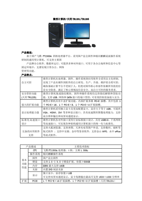
微型计算机-天玥TR1231/TR1235产品概述:基于国产飞腾FT1500A四核处理器平台,采用国产昆仑固件和银河麒麟桌面操作系统研制的通用型计算机,可支持主要国产品牌办公软件、数据库运行,可提供多种对外接口,可用于各办公场所和信息中心等固定环境中,支撑实现日常办公、网络管理等功能。
产品特点:微型计算机-天玥TR117*产品概述:基于国产龙芯3A3000四核处理器平台,采用国产昆仑固件和中标麒麟桌面操作系统研制的通用型计算机,可支持主要国产品牌办公软件、数据库运行,可提供多种对外接口,可用于各办公场所和信息中心等固定环境中,支撑实现日常办公、网络管理等功能。
微型计算机(一体式)-天玥TR3231产品概述天玥TR3231微型计算机(一体式)是以国产飞腾FT1500A处理器为核心,采用符合UEFI2.3标准的国产昆仑桌面版固件和麒麟桌面操作系统的通用型计算机。
台式计算机(一体式)主要由主板、内存、硬盘、独立显卡、光驱、风扇模组、电源模块、机箱组成,可支持主要国产品牌数据库(达梦、金仓、南通、神通等)连接工具的运行,支持可信硬件模块扩展,可提供多种对外接口,适用于我军各级固定指挥所、通信站台、网络控制室、值班室试验基地、办公场所和信息中心(节点)等固定环境中,支撑实现指挥作业、通信业务、安全控制、网络管理、值班交换等功能。
Mini 主机-天玥TR5171产品概述:天玥 TR5171 型 Mini 主机是专门针对“两个终端”问题研制的一款小型国产化终端产品,基于龙芯 3A3000 处理器,搭载中标麒麟操作系统,同时内置 KVM 功能,用最小的体积解决“两个终端”切换问题。
产品支持主流国产品牌办公软件,主要用于各办公场所,降低终端占地面积。
产品特点:Mini 主机-天玥TR5231产品概述:天玥 TR5231 型 Mini 主机是专门针对“两个终端”问题研制的一款小型国产化终端产品,基于飞腾处理器,搭载银河麒麟操作系统,同时内置 KVM 功能,用最小的体积解决“两个终端”切换问题。
MP2000维修手册

防冷凝加热器的安装 ............................................................................ 31 纸盘加热器 .......................................................................................... 32
环境 .................................................................................................... 3 机器水平 ............................................................................................. 4 所需最小空间...................................................................................... 4 电源要求 ............................................................................................. 4 复印机的安装 ........................................................................................ 5 外围设备的电源插座 ........................................................................... 5 附件检查 ............................................................................................. 5 安装程序 ............................................................................................. 6 盖板安装.............................................................................................. 10 附件检查 ........................................................................................... 10 安装程序 ........................................................................................... 10 ARDF 安装 ...........................................................................................11 附件检查 ............................................................................................11 安装程序 ........................................................................................... 12 ADF 安装............................................................................................. 15 附件检查 ........................................................................................... 15 安装程序 ........................................................................................... 16 双斗纸盘单元安装 ............................................................................... 19 附件检查 ........................................................................................... 19 安装程序 ........................................................................................... 19 单斗纸盘单元安装 ............................................................................... 24 附件检查 ........................................................................................... 24 安装程序 ........................................................................................... 24 单斗纸盘安装 ...................................................................................... 28 附件检查 ........................................................................................... 28 安装程序 ........................................................................................... 28
BenQ LX770 LH770项目器通过RS232控制指南说明书

LX770/ LH770Projector RS232 Command ControlInstallation GuideT able of ContentsIntroduction (3)Wire arrangement (3)RS232 pin assignment (3)Connections and communication settings (4)RS232 serial port with a crossover cable (4)Settings (4)RS232 via LAN (6)Settings (6)RS232 via HDBaseT (6)Settings (6)Command table (8)IntroductionThe document describes how to control your BenQ projector via RS232 from a computer. Follow the procedures to complete the connection and settings first, and refer to the command table for RS232 commands.Available functions and commands vary by model. Check the specifications and user manual of the purchased projector for product functions.Wire arrangementRS232 pin assignmentConnections and communication settingsChoose one of the connections and set up properly before RS232 control.RS232 serial port with a crossover cableSettingsOn-screen images in this document are for reference only. The screens may vary depending on your Operating System, I/O ports used for connection, and the specifications of the connected projector.1. Determine the COM Port name used for the RS232 communications in Device Manager.PC or laptopCommunication cable (crossover)D-Sub 9 pin (female)D-Sub 9 pin (male) on a projector2.Choose Serial and the corresponding COM port as the communication port. In this given example,COM6 is selected.3.Finish Serial port setup.Check the baud rate of the connected projector from its OSD menu.8 bitRS232 via LANSettings1. Find the Wired LAN IP address of the connected projector from the OSD menu and make sure the projector and the computer are within the same network.2.Input 8000 in the TCP port #field.RS232 via HDBaseTSettings1. Determine the COM Port name used for the RS232 communications in Device Manager .2.Choose Serial and the corresponding COM port as the communication port. In this given example, COM6 is selected.PC or laptopRJ45 port on a projectorLAN cablePC or laptopHDBaseT compatible device D-Sub 9 pinRJ45RJ45 port on a projectorLAN cableD-Sub 9 pin3.Finish Serial port setup.Check the baud rate of the connected projector from its OSD menu.8 bitCommand table∙ Available features differ by projector specification, input sources, settings, etc..∙ Commands are working if the standby power is 0.5W or a supported baud rate of the projector is set. ∙ Uppercase, lowercase, and a mixture of both types of characters are accepted for a command. ∙ If a command format is illegal, it will echo Illegal format .∙ If a command with correct format is not valid for the projector model, it will echo Unsupported item . ∙ If a command with correct format cannot be executed under certain condition, it will echo Block item .∙ If RS232 control is performed via LAN, a command works whether it starts and ends with <CR>. All the commands and behaviors are identical with the control through a serial port.© 2018 BenQ CorporationAll rights reserved. Rights of modification reserved. Version: 1.01-C。
hp officejet pro 8610 8620 8630 使用手冊说明书

8. 此組件中並無使用者可自行維修的零 件。 有關維修問題,請洽詢合格的維修 人員。
目錄
1 如何使用? ........................................................................................................................................................ 1
HP Officejet Pro 8610 e-All-in-One/HP Officejet Pro 8620 e-All-in-One/HP Officejet Pro 8630 e-All-in014 著作權 Hewlett-Packard Development Company, L.P.
2 準備開始 ............................................................................................................................................................ 3 可用性 ................................................................................................................................................... 4 HP EcoSolutions (HP 與環境) .........................................................
M-551

Model No.
Price Description
Setpoint Alarms (Only 1 Alarm Card Can Be Installed Into Base Meter)
LDP6-CDS10
$37 Dual setpoint relay output card
LDP6-CDS20
37 Quad setpoint relay output card
The meters have 4 setpoint outputs, implemented on plug-in option cards. The plug-in cards provide dual form “C” relays (5 A), quad form “A” (3 A), or either quadsinking or quad-sourcing open collector logic outputs. The setpoint
M-55
Process Inputs
Input Range
Accuracy* (18 to 28°C)
Accuracy* (0 to 50°C)
Max Impedance/ Continuous Display Compliance Overload Resolution
20 mA (-2 to 26 mA)
91.4 (3.60)
Dimensions: mm (in)
2.5 (0.10)
104.1 (4.10)
MOST POPULAR MODELS HIGHLIGHTED!
To Order (Specify Model Number)
Model No.
Price
南天自助终端产品手册

南天自助终端产品手册2014年南天自助产品中心产品部2014年4月目录1传统自助终端.....................................................大堂式多功能自助终端......................................Nantian BST-4200/C20..................................Nantian BST-5200 A20..................................穿墙式多功能自助终端......................................Nantian BST-4230/C21..................................壁挂式多功能自助终端......................................Nantian BST-3340/C22.................................. 2自助发卡机.......................................................大堂式发卡机..............................................Nantian BST-5200 B20..................................台式发卡机................................................Nantian BST-3340 H10.................................. 3自助回单机.......................................................大堂式自助回单机..........................................Nantian BST-5810A..................................... 4排队机...........................................................大堂式排队机..............................................Nantian BST-5200/E10.................................. 5其他.............................................................网银终端..................................................Nantian BST-4200/G20..................................预填单机..................................................Nantian BST-5200/B10..................................智能服务终端..............................................Nantian BST-4210 A24..................................存折补登机................................................Nantian BST-1100......................................1传统自助终端1.1大堂式多功能自助终端1.1.1N antian BST-4200/C201.1.1.1效果图1.1.1.2结构尺寸图1.1.1.3功能特点外形新颖:整机采用流线型设计;全注塑面板,美观大方;整机色调协调统一;全功能配置:支持存折补登、银行卡查询及转账等多种传统业务功能的同时,能够播放多媒体广告信息,并支持凭条/账单/发票等多种票据的自助打印功能;可扩展型强:支持激光打印机、发票打印机、条码扫描、非接触式IC卡等多种模块扩展功能;强大的卡业务处理功能:支持磁卡、IC、非接触式IC卡等多种卡片的读写功能;数据安全性高:采用硬件加密键盘;配备读卡器异型卡口及密码键盘防窥式设计,大大提高了用户个人信息的安全性;1.1.1.4标准配置1.1.1.5可扩展配置1.1.2N antian BST-5200 A201.1.2.1效果图1.1.2.2结构尺寸图1.1.2.3功能特点外形新颖:整机采用流线型设计;全注塑面板,美观大方;整机色调协调统一;全功能配置:支持存折补登、银行卡查询及转账等多种传统业务功能的同时,能够播放多媒体广告信息,并支持凭条/账单/发票等多种票据的自助打印功能;可扩展型强:支持激光打印机、发票打印机、条码扫描、非接触式IC卡等多种模块扩展功能;强大的卡业务处理功能:支持磁卡、IC、非接触式IC卡等多种卡片的读写功能;数据安全性高:采用硬件加密键盘;配备读卡器异型卡口及密码键盘防窥式设计,大大提高了用户个人信息的安全性;1.1.2.4标准配置1.1.2.5可扩展配置1.2穿墙式多功能自助终端1.2.1N antian BST-4230/C211.2.1.1效果图1.2.1.2安装尺寸图1.2.1.3功能特点户外穿墙式应用设计:高附着力,防酸碱腐蚀户外型塑粉喷塑;防水、防尘、防暴;超强的高低温适应能力;功能布局合理:引用ATM 导轨式拉出设计,前面框及各模块可拉出进行维护,方便、快捷;全功能配置:支持存折补登、银行卡查询及转账等多种传统业务功能的同时,能够播放多媒体广告信息,并支持凭条/账单/发票等多种票据的自助打印功能;可扩展型强:支持激光打印机、发票打印机、条码扫描、非接触式IC卡等多种模块扩展功能;数据安全性高:采用硬件加密键盘;配备读卡器异型卡口及密码键盘防窥罩,大大提高了用户个人信息的安全性;智能电源管理:掉电监控、掉电保护、自动维护、自动关机;1.2.1.4标准配置1.2.1.5可扩展配置1.3壁挂式多功能自助终端1.3.1N antian BST-3340/C221.3.1.1效果图1.3.1.2安装尺寸图1.3.1.3功能特点壁挂式设计:不受安装空间限制,可做离行式设备使用;强大的卡业务处理功能:支持磁卡、IC、非接触式IC卡等多种卡片的读写功能;多种扩展功能:条码扫描、非接触式IC卡、发票打印机、GPRS或CDMA无线通信模块;机身色彩个性化定制:机身颜色可根据用户需求进行个性化定制;数据安全:EPP硬件加密键盘,采用凹陷型设计,设计时充分考虑了用户信息安全性;1.3.1.4标准配置1.3.1.5可扩展配置2自助发卡机2.1大堂式发卡机2.1.1N antian BST-5200 B202.1.1.1效果图2.1.1.2安装尺寸图2.1.1.3功能特点先进的自助发卡模块,保障自助发卡的可靠性和安全性。
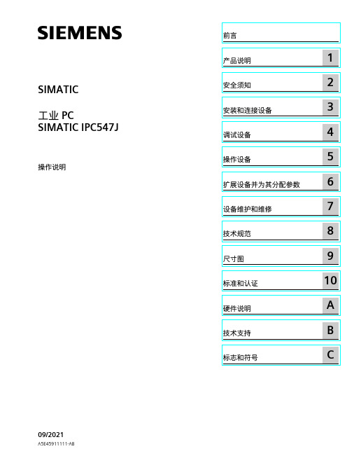
SIMATIC IPC547J SIMATIC 工业 PC SIMATIC IPC547J 操作说明
C
法律资讯
警告提示系统
为了您的人身安全以及避免财产损失,必须注意本手册中的提示。人身安全的提示用一个警告三角表示,仅 与财产损失有关的提示不带警告三角。警告提示根据危险等级由高到低如下表示。
危险 表示如果不采取相应的小心措施,将会导致死亡或者严重的人身伤害。
警告 表示如果不采取相应的小心措施,可能导致死亡或者严重的人身伤害。
Siemens AG Digital Industries Postfach 48 48 90026 NÜRNBERG 德国
A5E45911111-AB Ⓟ 09/2021 本公司保留更改的权利
Copyright © Siemens AG 2021. 保留所有权利
前言
本操作说明的用途 本操作说明包含 SIMATIC IPC547J 安装、电气连接、调试和扩展以及维护和维修设备所需 的全部信息。本操作说明是专为以下具有资质的专业人员编写的: • 装配工 • 调试工程师 • IT 管理员 • 维修与维护人员
SIMATIC IPC547J
SIMATIC 工业 PC SIMATIC IPC547J
操作说明
09/2021
A5E45911111-AB
前言
产品说明
1
安全须知
2
安装和连接设备
3
调试设备
4
操作设备
5
扩展设备并为其分配参数
6
设备维护和维修
7
技术规范
8
尺寸图
9
标准和认证
10
硬件说明
A
技术支持
B
标志和符号
小心 表示如果不采取相应的小心措施,可能导致轻微的人身伤害。
பைடு நூலகம்注意
HP TFT7600机架式一体化键盘显示器用户指南

简介 ........................................................................................................................................................ 5 TFT7600 RKM 的功能 ................................................................................................................................ 5 组件 ........................................................................................................................................................ 6 背面组件.................................................................................................................................................. 7
- 1、下载文档前请自行甄别文档内容的完整性,平台不提供额外的编辑、内容补充、找答案等附加服务。
- 2、"仅部分预览"的文档,不可在线预览部分如存在完整性等问题,可反馈申请退款(可完整预览的文档不适用该条件!)。
- 3、如文档侵犯您的权益,请联系客服反馈,我们会尽快为您处理(人工客服工作时间:9:00-18:30)。
工业微型计算机55172全国高等教育自学考试工业用微型计算机标准预测试卷(六)(考试时间150分钟)第一部分选择题一、单项选择题(本大题共20小题,每小题2分,共40分)在每小题列出的四个备选项中只有一个是符合题目要求的,请将其代码填写在题后的括号内。
错选、多选或未选均无分。
1.无符号二进制数10010111B对应的十进制数是 ( )A.653 B.327C.151 D.1252.十进制-58对应的二进制原码是 ( )A. 10111010BB.10011111BC. 11100000BD.11100001B3.十进制- 66对应的二进制补码是 ( )A. 10111010BB.10111110BC. 11100000BD.11100001B4.地址总线为20位的微机系统中其内存最大容量为 ( )A.1024 KB B.2048KBC.2048MB D.4096MB5. O1O1O111B和O11OO11OB都是八位二进制补码数,其相加的结果应为 ( ) A.3DH.溢出 B.3DH,未溢出C.OBDH.溢出 D.OBDH,未溢出6.设( DS) =2872H,偏移量为86H,该字节的物理地址是 ( )A.28F8H B.287 A6HC.28806H D.AE720H7.在中断矢量表OOOOH:0028H-OOOOH:002BH处存储的中断矢量所对应的中断类型号为( )A.8 B.7C.10 D.38.-条指令中目的操作数不允许使用的寻址方式是 ( )A.寄存器寻址 B.立即数寻址C.变址寻址 D.寄存器间接寻址9.设SP =1FFAH,执行下列指令后,SP寄存器的值是 ( )PUSH BXPUSH AXA.1FF6H B.2002HC.1FFEH D.1FFBH10.判断当CX =0时,转LOP执行的错误指令是 ( )A.CMP CX,0 B.MOV AX,CXJZ LOP JZ LOPC.OR CX.CX D.JCXZ LOPJZ LOP11.下面的名字中,无效的是 ( )A.NUM_ONE B.2NUM_ONEC. NUM_2D. NUM_TWO12.若执行指令TEST AL,OIH后,标志位ZF =1,则AL中的内容必定是( )A.偶数 B.奇数C.正数 D.负数13.容量为4KB的EPROM芯片是 ( )A.2716 B.2732C.2764 D.2712814. DOS系统功能(INT 21H)9号调用要求将待显示字符串的首址送入 ( ) A.DS:DX B.CS:DXC.DS:BX D.CS:BX15. 8088CPU响应中断后,在发出第一个中断响应信号INTA的同时,内部自动实现 ( )A.开中断 B.关中断C.保护DS D.中断返回16.对于Intel 8251,如果发送缓冲器为空,则8251引脚——变高?要求CPU 提供新的数据。
( )A.INTR B.TxD17.当向8253芯片写入控制字56H后,则该芯片的1通道工作在 ( )A.方式0 B.方式1C.方式2 D.方式318.设串行异步通信的数据格式是:1位停止位,7位数据位,1位校验位,l位起始位,若传输率为1200位/秒,则每秒传输的最大字符个数为 ( ) A.10个 B.110个C.120个 D.240个19.某10位的A/D转换器输入电压范围为0—10V,当输入电压为3伏时,其转换结果为.( )A.102 B.204C.307 D.40920. PC/104总线的引脚为 ( )A.62根 B.128根C.98根 D.104根第二部分非选择题二、填空题(本大题共10小题,每小题1分,共10分)请在每小题的空格中填上正确答案。
错填、不填均无分。
21.指令MOV DX,[BX +SI],其源操作数的寻址方式是________。
22.衡量半导体存储器的最重要的指标是存储器芯片的________和存储速度。
23.设8255A口工作于方式O输出,C口高4位输出,B口方式0输入,C口低4位输入,其控制字应为________H。
24.两台计算机采用RS - 232C串口通信时,最少的连接线数是________根。
25.若要定时器/计数器芯片8253的通道0输出连续的方波信号时,应将其设置为方式________。
26. EIA RS - 232C串行通讯标准是在____针接插件上定义了串行通信的有关信号。
27.ftp://ftp. pku. cn/pub/filel/readme. txt表示要通过________连接来获得一个名为readme. txt的文本文件。
28.设某ROM芯片的地址范围为OOOOH~ OIFFH,则该ROM芯片可寻址单元有____个。
29.在A/D转换期间,要求模拟信号保持稳定,当输入信号速率较快时,必须采用________。
30. IP地址长度为________位。
三、程序分析题(本大题共6小题,每小题4分,共24分)31.已知DS= ES= 2000H执行下列程序:MOV SI,301HMOV DI,300HMOV CX,4CLDREP MOVSBINT 3DS:301H DB 22H,33H,44H,55H程序运行后结果为:( 20300H)= ________H(20301H)= ________H(20302H)= ________H(20303H)=________H32.分析如下程序段,MOV AX,OIHMOV BX,02HMOV CX,03HLOP: INC AXADD BX,AXSHR AX,1LOOP LOPHLT请回答:程序执行后AX=____,BX=____ 33.分析下面的程序段:XOR AX,AXMOV AX,6A3EHMOV CX,0203HRCL AH,CLXCHG CH,CLRCR AL,CLINT 3请回答:程序执行后AX=____;CF=____。
34.用DEBUG调试如下程序段:MOV SI,OMOV AL,1000[ SI]LP:INC SICMP SI,08HJAE A11CMP.AL,1000[SI]JGE A22MOV AL,1000[SI]A22:JMP LPA11:INT 3DS:1000H DB 34H,47H,78H,77HDB 88H,99H,OAAH,OFFH则程序执行后,AL=____该程序的功能是:____35.阅读下列程序,说明程序执行后AH、AL、CF、SUM单元的值。
MOV AH,OMOV AL, NUM1ADD AL, NUM2DAAADC AH,0MOV SUM, ALINT 3NUM1 DB 73HNUM2 DB 66HSUM DB?AH=____ ,AL=____ ,CF=________SUM单元的值=____36.已知参数定义和梯形图程序如图所示,试说明程序控制功能。
按钮AN1 1:001100按钮AN2 I:002/01电机M 0:003/01五、简单应用题(本大题共2小题,每小题5分,共10分)38. 8255A作为8位数字显示器接口如图所示,8255A的口地址已设定为120H-123H,使位6的数字显示器显示字符6的程序段如下所示,请在空格中填写正确的内容。
MOV DX,____;初始化MOV AL, ________OUT DX, ALMOV DX,____;输出字形码MOV AL,________OUT DX.ALMOV DX,120H;输出位选码MOV AL,____OUT DX.AL39.设串行通信接口芯片8251A的数据端口地址为218H,状态端口地址为219H,并已经初始化。
用查询的方式发送数据,被发送的字符在数据段2000H 单元开始的内存区。
发送完“$”后结束发送。
请在空格中填写正确的内容。
MOV BX.2000HMOV________`,219HLOOP: IN____,DXTEST AL,OIH;检查TXRDYJZ________;数据发送缓冲区不空,继续检测MOV DX.MOV AL,[BX];取待发送字符OUT DX.ALTEST AL____;检测是否结束符JZ EXITINC BXJMP LOOPEXIT:INT 3六、综合应用题(本题8分)40.如图所示,8255A口外接一个共阴极LED八段显示。
PB7外接一个开关键K,当K键断开时不显示,闭合时,循环显示‘0’~‘5’,每秒钟显示变化一次。
设8255的端口地址是(218H-21BH),请在空格中填写正确的内容。
START: MOV DX, ________MOV AL, 82H;8255控制的初始化OUT DX,ALMOV DX, ________IN AL,DX;读B口开关状态AND AL, ________;检查开关闭合JZ DISPOFFMOV BX,200HMOV CX,____DISP: MOV AL,[BX];取字型码MOV DX,____OUT DX,AL;LED显示CALL DELAY1;调用延时1S子程序INC________________DISP;循环显示JMP STARTDISPOFF:MOV DX,218HMOV AL, ________;不显示OUT DX,ALJMP STARTDS:200HDB 3FH,06H,5BH,4FH,66H,6DH工业用微型计算机标准预测试卷(六)答案详解一、1.C [解析]10010111B对应的十进制为:27 +24 +22 +21 +20 =151 2.A [解析]负数的原码最高位为符号x位,为1,低7位为数据y位3.B [解析]负数的补码=反码+14. A [解析]220= 210×210 =1024k(注:1k= 210= 1024)5.C [解析]两正数相加后最高位为1,溢出6.B [解析]物理地址为DS的值左移四位后与偏移量相加7.C [解析]10 *4= 40= 28H8.B [解析]立即数不能作为目的操作数。
9.A [解析]PUSH指令使SP减2,POP指令使SP加210.B [解析]MOV指令不影响标志位。
11.B [解析]名字的第一个字符不能是数字。
12.A [解析]AL内容的DO位为O,为偶数。
13. B 14. A 15. B 16. D 17. D18.C [解析]一个字符的长度为1+7 +1+1 =10。
19.C [解析]20. D二、21.基址加变址寻址22.容量23. 8324.3[解析]TX,RX及地线25. 326. 2527. FTP28. [解析]29= 51229.采样保持器30. 32三、31. (20300H) =22H (20301H) =33H(20302H) =44H (20303H) =55 H32. AX =1,BX =8 [解析]完成2+2 +2 +233.程序执行后AX =514FH,CF=134. AL =78H,该程序的功能是:求有符号数的最大值。
