瑞典VOC系列通用说明书最终版
jotun hardtop one湿固化丙烯酸聚硅氧烷面漆(0t2) 产品技术说明书

湿固化丙烯酸聚硅氧烷面漆 (0T2)这是一款单组份,湿气固化的丙烯酸聚硅氧烷涂料。
本产品不含异氰酸酯,在火工/焊接或发生火灾事故时不产生二异氰酸酯. 有优异的保光性和保色性。
它是一款高固体含量的产品。
此产品可在固化的任何阶段进行复涂。
施工方式为刷涂和辊涂。
施工性能良好且不易干喷。
在大气环境下作为面漆使用。
认证和证书本产品对绿色建筑标准得分会有贡献,请参见绿色建筑标准章节。
颜色可采用工业调色机体系(MCI)进行调色典型用途船舶漆领域:推荐用于干舷、甲板和船的上层建筑。
工业保护漆领域:推荐用于近海环境,如炼化厂、发电站、桥梁和建筑。
性能测试/标准描述光泽度 (GU 60 °)ISO 2813VOC - 美国 / 香港US EPA 方法 24 (测试值)(CARB(SCM)2007, SCAQMD rule 1113, Hong Kong)VOC- 欧盟IED (2010/75/EU) (理论值)所列数据是基于工厂批量生产的产品,因颜色不同会有些许变化。
闪点ISO 3679 方法 130 ℃有光(70-85)245 克/升190 克/升密度1.4kg/l 光泽描述: 根据佐敦功能涂料的定义理论值VOC- 欧盟EU VOC Directive 2004/42/CE (ISO 11890-2) (经测试)VOC- 中国GB/T 23985-2009 (经测试)243 克/升159 克/升湿膜厚度理论涂布率6080121001307.2微米微米平方米/升---该产品可用以下方式施工喷涂:无气或空气喷涂均可使用。
刷涂:建议. 注意要达到特定的干膜厚度。
辊涂:建议. 注意要达到特定的干膜厚度。
稀释剂:佐敦2号稀释剂当基材温度低于5摄氏度时,使用佐敦7号稀释剂可提高流平性。
通常不需要稀释。
在极端环境下施工请咨询当地的佐敦代表。
稀释时请勿超过当地的环境法规要求。
注意:当韩国VOC法规《韩国清洁空气保护法》和它对应的稀释限值与推荐稀释体积不同时,以前者为准。
汽车涂装排放VOC明细一览

一、国外相关控制标准1)欧美美国、英国和德国早在20年前就制定大气净化法(CAA:Clean Air Act)、环境保护法和排放防治法(TA-Lult)来控制汽车涂装的VOC排放。
但各国标准的VOC定义、控制目标及控制内容等都存在着差异。
美国主要通过限制涂料及有机溶剂中VOC含量来减少有机污染物排放。
联邦环境署(EPA)修订的国家大气净化法(CAAA),在原有VOC的控制基础上又增加有毒有害大气污染物(HAPs:hazardous air pollutants)。
在大气净化法中根据各州的实际情况规定了相应的基准值RACT、BACT、LAER,见表1。
表1主要发达国家汽车涂装排放VOC限值比较(单位:g/m2)1998年美国制定了国家汽车表面涂装VOC排放标准,排放限值见表2。
2008年加利福尼亚州颁布的1151号法规中汽车表面涂装VOC的限值为250g/L。
表2 美国车辆表面喷涂VOC含量标准1996年欧盟颁布了溶剂指令1999/13/EC,以削减工业生产的VOC排放量。
主要控制对象包括汽车涂装、卷材涂装、金属涂装、木工涂装等,要求现有源在2007年10月30日前完成改造。
其中欧盟汽车涂装限值以单位涂装面积VOC排放总量(g/m2)表示。
排放限值见表3(按溶剂的年耗量、汽车车身的年产量和车身类型、新、老涂装线来划分限值)。
表3 欧盟汽车涂装VOC排放限值随后颁布的2004/42/EC指令对建筑物和汽车修补等涂料规定了VOC含量限值见表4。
要求欧盟各国在2010年采取减排措施以达到标准要求。
表4欧盟汽车修补涂料VOC含量限值2)日本2000年日本汽车工业会规定VOC排放限值为60g/m2。
2005年日本政府颁布了修订版大气污染防治法和189号政令,明确了控制指标、设施基准和实施日期。
汽车涂装设备排风机VOC排放浓度限值(排风能力10万m3/h以上):现有700ppmc;新源400ppmc;其他700ppmc(ppmc表示换算成碳的容量比百分率)。
VOC-600C智能型检针器使用说明书
(触摸式强抗干扰)P1/3一、安装调试:1.选择好摆放位置,注意一定要远离会产生电磁辐射的设备。
如高频机、电脑针车,吊扇,充绒机及移动的金属,如手机、剪刀、钥匙圈、电梯等。
2.选好位置后,将机器螺杆旋杆,使四只万向轮离开地面约5mm,调整好机器水平,并将螺帽旋上固定。
3.检查电源插座,用万用表测试一下。
电源电压应为AC220V+-5%,如偏高或偏低,应加装自动调压设备,以确保能稳定有效地工作。
4.电源插座一定要有可靠的接地线,以确保安全。
5.打开电源开关,电源指示灯亮,同时操作面板上各指示灯都闪烁几下后显示当前时间,进入待机状态。
6.按启动键后,机器启动进入检测状态,放上随机附送的标准测试块试机,应能报警、输送带应返回,返回后应能自动启动。
7.根据不同的检测要求,调整好灵敏度。
(本机特设有灵敏度和感应度双十段0-100电平显示)。
8.有条件的工厂,为了防止被检衣物多、堆放乱,往往会造成未检衣物混入检针合格衣物中,造成不必要的重大损失!所以建议工厂能设专门的检针室,以确保万无一失!二、使用方法:1.插上电源开关,打开电源开关,电源指示灯亮,同时操作面板上个指示灯和显示屏闪烁三下后显示屏显示当前的时间。
此时您可以调整好灵敏度,按箭头向上表示灵敏度上升同时指示灯一次向上点亮,每按一下上升一级。
按箭头向下表示灵敏度下降同时指示灯依次向下熄灭。
2.按功能设置键,进入年、月、日、时间、倒带时间设置,首先按一下功能设置键,显示屏显示“Y200X”,其中X不断在闪烁表示请选择,X实际上是某一数字如“5”“2”“3”什么的。
请按上下灵敏度箭头选择(触摸式强抗干扰)P2/3年份,选好后按功能设置键确定,这样年份就设定完成了。
此时显示屏显示“daada”,并且“aa”在不断闪烁表示请选择,同样“aabb”实际显示的都是数字,“aa”表示月份如“01”“03”,您同样按灵敏度上下箭头选择月份,选好后按功能设置键确定,这样月份就设定完成了。
丙烯酸聚氨酯面漆 说明书

性能特点
基材*:钢材 表面处理*:SSPC-SP10 测试系统*: 1 层 Macropoxy 646 环氧中层漆 150微米 干膜厚度 1 层 Acrolon 218 HS 高光面漆 100微米 干膜厚度
*除非另有说明,以下数据均由此系统获得
不稀释 : 稀释10% : 稀释15% :
测试名称 耐磨性 附着力 腐蚀环境 抗直接冲击 抗干燥环境温度 延展性
5.22
施工指南
表面处理 施工条件
温度: 最低4°C,最高49°C (空气、被涂表面和涂料) 至少高于露点2.8°C 最大为85%
为了确保足够的附着力,被涂物表面必须清洁、干燥和坚固。除 去所有的油、灰、脂、污垢、松动的锈层和其他外部附着物。 铁和钢材表面: 按照SSPC-SP1先用溶剂除去被涂表面的油脂,最低的喷砂处理等 级要求是SSPC-SP6/NACE3规定的商业喷砂处理。 要想获得更好 的效果,应该按照SSPC-SP10/NACE2使用有棱角锐利的金属磨料 对所有表面进行近似出白喷砂处理,最佳表面粗糙度为 (25-50 微 米)。应在表面处理的当天和裸露的金属表面产生闪锈前涂装底漆。 铝材表面: 按照SSPC-SP1的标准清除所有的油、脂、污物和其它的金属氧化 物。必须施工底涂。 镀锌钢材表面: 被涂镀锌钢材至少应在自然环境中老化6个月后才可进行涂装。 按 照SSPC-SP1先用溶剂对被涂表面进行清洗。如果没有经过自然老 化或者被涂表面经过铬酸盐或硅酸盐处理,按照SSPC-SP1先用溶 剂对被涂表面进行清洗,然后进行局部涂装试验。待其干燥至少一 星期后进行附着力测试。如果附着力差,则应该按照SSPC-SP7进 行扫砂处理,除去原有涂层。如果被涂表面电镀层出现锈蚀,至少 应当按照SSPC-SP2进行一次手工工具清理,并在当天或闪锈锈产 生前涂装底漆。 浇注混凝土表面: 新的表面 按照SSPC-SP13/NACE 6的标准或ICRI03732,CSPI-3进行表面 处理.被涂表面必须干燥、清洁,密实,以保证良好的附着力。最少 在 24°C温度下保养28天,去除所有松散的灰浆和外来物质表面必 须清除泥浆、混凝土灰尘、污垢、脱膜剂、水汽固化膜、松散的水 泥和固化剂,用Steel-Seam FT910来填补孔洞、气孔裂缝等瑕疵。 通常参照以下标准: ASTM D4258标准用于清洁混凝土。 ASTM D4259标准用于打磨混凝土。 ASTM D4260标准用于蚀刻混凝土。 ASTM F1869标准用于测量混凝土的水蒸气通过率。 SSPC-SP 13/Nace 6是混凝土表面处理标准。
欧盟WEEE指令中文版
欧洲议会和理事会2003年1月27日第2002/96/EC号关于报废电子电气设备指令(仅供参考)欧洲议会和欧盟理事会,注意到建立欧洲共同体的条约,特别是其中第175(1)条,注意到欧盟委员会的提案,注意到欧盟经济社会委员会的意见,注意到欧盟地区委员会的意见,按照欧洲共同体条约第251条所制订的程序并根据协调委员会2002年11月8日通过的联合文本,鉴于:(1)共同体环境政策的重点目的是维持、保护和提高环境质量,保护人类健康及合理谨慎地使用自然资源。
这项政策的制定是基于预防原则和其他原则,如应采取预防措施、资源方面的环境破坏应优先补救以及制造污染者应赔偿。
(2)共同体与环境和可持续发展相关的政策和行动计划(第五个环境行动计划)①认为可持续发展的实现要求当前的发展模式、生产模式、消费模式和行为模式有明显变化,并尤其倡导降低自然资源的浪费性消耗和预防污染。
考虑到适用废弃物预防、回收和安全处置原则,项目要求将报废电子电气设备作为需加以规范的目标领域之一。
(3)关于检查共同体废弃物管理战略的1996年7月30日欧盟委员会通讯指出,由于在无法避免废弃物产生的地方,废弃物的材料和能量应可再利用或者恢复。
(4)1997年2月24日,理事会在关于共同体废弃物管理战略②的决定中坚持认为,为了减少废弃物处置量和保护自然资源需要促进废弃物的恢复,特别通过再利用、再循环、合成和从废弃物中获得能源的方式,并承认在任何特殊情况下所选择的措施必须考虑到对环境和经济的影响,但是直到取得科技进步和生物周期分析技术得到进一步发展,再利用和材料回收在作为最佳合乎环境要求的选择时方可被作为优先考虑的措施。
理事会同时也要求委员会尽快制定重点废弃物流计划,包括报废电子电气设备,的适当的后续措施。
(5)欧洲议会在其1996年11月14日的决定③中,要求委员会提供一些关于重点废弃物流,包括电子电气废弃物的提案,并要求这些提案基于生产者责任原则。
产品技术手册A

产品技术手册第一部分、什么是艾尔柯家居环境智能集成?艾尔柯家居环境智能集成即Smart Home & EnvironmentIntegration,主要包括环境集成和智能集成。
一、艾尔柯家居环境集成要求温度:衡量空气冷、热程度的指标;一般卧室夏天高标准温度24℃-26℃,冬天18℃-21℃、儿童房、老人房温度夏天高标准温度25℃-27℃,冬天20℃-23℃、卫生间夏天高标准温度24℃-26℃,冬天23℃-25℃。
湿度:指空气相对湿度即空气中所含水蒸气的比例指标;空气温度升高时,湿度则会降低,一般卧室夏天湿度≤60%RH,冬天≥40%RH、书房夏天湿度≤55%RH,冬天≥40%RH、儿童房、老人房夏天湿度≤55%RH,冬天≥40%RH。
空气的洁净度:衡量空气清洁程度的指标;浮尘量≤0.15mg/㎥一氧化碳≤10PPM 二氧化碳≤800PPM、无灰尘、人及宠物的皮屑、过量湿气、烟气、各种异味、虫螨等过敏源,各类病菌、二氧化碳(Voc 甲醛苯氢气等)。
噪音:发生体做无规则振动时发出的声音,是一类引起人烦躁、或音量过强而危害人体健康的声音;研究表明,30分贝以下属于非常安静的环境,如播音室、医院等应该满足这个条件。
40分贝是正常的环境,如一般办公室应保持这种水平。
风速:衡量中央空调室内机送风速度的指标,夏季≤0.3 m/s,冬季≤0.2m/s。
新风量:衡量从室外引进新鲜空气的指标;一般无吸烟卧室新风量高标准35l/s、有吸烟的客厅新风量高标准30l/s、餐厅新风量高标准35l/s、吸烟的书房新风量高标准50l/s。
高品质的水:1、净水:水中无余氯、异色异味、藻类及其固体悬浮物、无铁、金属离子、氢硫化物、无细菌、无有机化学物质2、软水:中国标准软水Less than 50毫克/升、美国标准软水Less than 17.0毫克/升3、直饮有氧健康水。
二、艾尔柯家居环境智能集成生活六化的要求人性化:家居环境产品的设计“以人为本”,充分考虑使用者的年龄、层次、生活习惯、爱好、嗜好和极好的生活便利性。
瑞典VOC系列通用说明书最终版

When Inserting The Lock Body, hook The Upper And Lower Bolt.
Tihten The Four Set Screws On The Lock Body.
Notes The Connection Lines Are Divided Into The Internal And The External.please Select The Right Line To Pull Through The Two Sides Of The Door According To Indications Onthe Tag . Please Do Not Make A Misake
Insert The Big Square Shafts With Them Facing The Correct Directions.
4.3 Install Outer Panel
pressure spring of square shaft
small square shaft connecting bolt
Turn The Handle To Check Whether It’s Securely Fixed.
Selection And Adjustment Of Lock Body 4
4 Installation of Smart Lock
4.1 Installation Lock Body
Place The Lock Body Into The Door Leaf Processed To The Specified Dimension Pull The Connection Lines Of Lock Body Inner And Outer Panels Through The Two Sides Of The Door In Accordance With Indications On The Tag.
sharp_vocs_a1du5p2cp005b_specifications说明书
haiNo.:Date: 2018/08/21制品规格书SPECIFICATIONSvoc s sensorModel Name:A1DU5P2CP005B8.使用和保管上的注意事项/Important Notices for Use / Storage8-1 由于规格书规定范围外的使用不能保证,绝对禁止。
Any usage not conforming to this document is not allowed, as we take no responsibility for any usage exceeding this specifications.8-2 由于该制品是高密度集成回路(ESD耐性:2kV人体模型)搭载的电子部品,组装时,请注意静电气対策。
The ESD tolerance is 2kV(HBM), Please manage ESD when assembling.请不要放置在灰尘多的场合。
该制品请不要直接暴露在尘埃・盐分・气体(SO2, H2S, Cl2, NH3)・酸・强碱等中。
The units must not be used in the environment with heavy dust. This product is not allowed to exposure directly to dust, salinities, and the gas such as SO2, H2S, Cl2 and NH3,acid,alkari etc.8-3 该制品作为屋内設置使用设计,设置在受潮气影响的场合(盐害地域)时,请采取装配側不直接受湿气和盐分影响的对策。
This product is designed for the indoor installation. Please use it after considering measures that moisture and a direct salt do not influence on the set side when setting it up in the place (salt damage region) where the influence of the sea breeze is received.8-4 不可接触水滴、溶剂、油脂等。
voc检测仪说明书

目录
使用前须知 ................................................................................................................................1 注 意..........................................................................................................................................1 特别提示 ....................................................................................................................................1 警 告..........................................................................................................................................1 标准配置 ....................................................................................................................................2 产品概述 ....................................................................................................................................2 主要部件 ....................................................................................................................................2 技术指标 ....................................................................................................................................3 检测范围及分辨率.....................................................................................................................3 电池充电 ....................................................................................................................................4
voc list
单词表词汇 (P163-5) Teamworkto allocate (roles) 分配(角色)to contribute /make a contribution 贡献to co-operate 合作project team 项目团队to take on (responsibility) 承担责任team-building 团队建设to trust 信赖Trainingto agree on objectives 达成一致目标benefit 利益to bring in a consultant 聘请顾问to come up with (ideas) 想出主意to measure (progress) 估量(进步)seminar 研讨会to set (targets) 设立目标survival course 生存训练to work on (managerial skills) 致力于管理技能to work towards (objectives) 朝共同目标努力Generaladvertisement 广告attitude 态度effective 有效的expatriate 居住在国外的(人),侨民honest 诚实的to make (arrangements) 作出安排to put on (an event) 演出schedule 安排under pressure 在压力下词汇准备work towards a common objective 朝同一个目标共同努力share information 共享信息different point of view 不同的观点(be) under pressure 有压力toiletries 化妆品厂,清洁、化妆用品公司major brand 主导品牌sales department 销售部门sales staff 销售人员company culture 公司文化expatriate 旅居海外的management consultant 管理顾问managerial skills 管理技能creative thinking 创新思维team building 团队建设effective management style 有效的管理方式a survival course 生存技巧培训课程food and accommodation 食宿profile 简介,小传,概况simulation 模拟训练marketing mania 营销激情go for profit 追求利润behind schedule 进度落后计划stick to the schedule 严格按照计划进行参考词汇和表达co-operative 齐心协力的have communication problems 交流有困难attach importance to team building重视团队建设develop team work 开拓团队协作an effective team 精锐的团队a high-performance unit 高效的团队exchange of views 交流看法emphasize team spirit 强调团队精神share the same value 具有相同的价值观collective efforts 共同的努力Arrangement:asap (as soon as possible)to cancel (a meeting) 取消to confirm (arrangements) 确认deadline 最后期限to postpone (a meeting) 延长Telephone phrasesCan I take a message?Could I ask who’s calling? Could I speak to …?Could you spell that, please? I’ll ask he r to call youI’ll give him the messageI’ll put you throughI’m afraid she’s not hereI’m ringing about…Thanks for callingThis is…General:to adapt 适应answering machine 听筒complimentary (tickets) 免费(票)to decline 婉言谢绝native speaker 英语本族语人to raise (awareness) 提高意识to raise (your voice)to return a call 回电话sensitive 敏感的to simplify (your language) 简化trade fair 交易会voice mail 语音信息词汇准备international communication 国际交流official language 官方语言language skills 语言技能exceed 超越over-estimate 过高地估计manageable 便于管理understate 轻描淡写culture-specific 某一文化所特有的work environment 工作环境the business world 商界seminar 研讨会management 管理人员follow-up evaluation 后续评估supplier 供应商department training budget 部门培训预算deadline 最终期限voice mail 语音信息answering machine 录音电话(英国英语用answer phone)half-year sales report 半年度销售报告complimentary ticket 免费赠送的票native speaker 操本族语言的人time schedule/ 时间安排表Ericsson全名为Ericsson Telecommunications瑞典爱立信电讯公司Stockholm 斯德哥尔摩(瑞典首都)Helsinki 赫尔辛基(芬兰首都)Scandinavian 斯堪的纳维亚(北欧地区,包括挪威,瑞典,丹麦,冰岛等国家)Copenhagen 哥本哈根(丹麦首都)Danish Telecommunications Trade Fair 丹麦电子通信交易会参考词汇和表达:the fast speed makes it difficult to follow 语速太快跟不上local accent 地方口音idiomatic language 俗语fail to understand the slang expressions 不能理解俚语difference in cultural background create barriers in communication文化背景差异造成交际障碍cannot appreciate English culture-specific humor 不能欣赏英语文化中特有的幽默。
VOC气味培训资料-内部受控版1605 - 副本

成果 VOC工程规范 气味工程规范 气味试验能力建立 气味人员培训 长安VOC审核通过
三、 SAI气味和VOC推进和进展
回顾复习-2 1、SAI的VOC和气味的工程规范是以 长安汽车 的基准进行分解; 2、VOC过程控制和固化思路: 原材料固化 + 生产工艺固化 + 包装运输固化 3、SAI的VOC和气味零部件分解为 十 类; + 实验测试固化 ;
易挥发性有机化合物(vvoc):小于0℃一50℃ 挥发性有机物(voc):50℃一260℃ 半挥发性有机化合物(svoc):260℃一380℃ 颗粒状有机物(pom) :380℃以上
二、VOC及气味简介
2、VOC及气味来源 汽车VOC及气味主要来源 汽车 气 主 来
材料源头 工艺过程 辅助材料
提 纲
一、VOC和气味背景及必要性 、VOC和气味背景及必要性 二、VOC和气味简介 三、SAI气味和VOC推进和进展 四、VOC和气味标准解读
1、VOC实施原则 2、VOC工程规范 3、气味工程规范 4、报告分析 报告分
五、VOC和气味优化方法和案例分享
1 VOC和气味分解方法 1、VOC和气味分解方法 2、VOC案例分享 3、气味分解案例分享
总成达到客户要求的前提且分析无风险可提出申请规范工程规范为基础原材料仓储生产工艺过程参数包装方案物流方案风险可提出申请由sai审批规范工程规范为基础原材料仓储生产工艺过程参数包装方案物流方案风险可提出申请由sai审批以实验结果为固化基础33以实验结果为固化基础签署voc固化协议voc和气味标准解读原则上零部件以本规范的标准执行空调范围2voc工程规范原则上零部件以本规范的标准执行空调箱总成若客户有特殊要求按照客户要求进行采样袋式法a采样样品必须是按照正常生产工艺过程和包装运输或模拟包装过程的产品
瑞典達氏空氣消毒機DMF115操作手冊说明书

Dustie Air Sanitizer 瑞典達氏空氣消毒機Please read this operating manual,Before using this product.請在使用本產品前,閱讀本操作手冊Version:1152021V2安全重要提示使用前請詳細閱讀本操作說明指示,並妥善保存,以便於日後參考。
本說明書適用於DMF115系列型號產品,請依照所購買機型操作。
當我們在使用電器用品時,應具備最基本的安全常識,以避免火災,觸電及其他傷害的發生。
因此,請遵守以下指示。
將空氣消毒機從包裝盒中取出,可置於衣櫥、鞋櫃、浴室及冰箱等需要消毒的環境內。
產品進出風口避免有異物堵塞,請保持本產品釋放順暢,利於空氣循環。
產品表面請勿覆蓋毛巾等物體,保持機器周圍空氣暢通,並處於壹個相對密閉的空間環境內進行使用。
請保持雙手乾燥時使用本產品,禁止用液體直接清洗本產品。
禁止遮擋進出風口並保持暢通。
禁止將本產品作為玩具提供給兒童玩耍。
禁止在產品運行提示聲響時有人 寵物在現場及直接對著產品以口鼻吸入。
禁止將產品置入冰箱冷凍室內。
非專職人員或未授權修理人員,不得自行維修或改造本產品。
不可在充電的狀態下使用本產品。
7部品名稱1234充電端口電池容量提示燈工作指示燈電源開關 (普通模式 /強力模式)5釋放口8產品規格品名型號額定電壓輸出功率工作原理適用環境空氣消毒機DMF115DC 5.0V1.0W臭氧冰箱/鞋櫃/衣櫥電池容量工作溫度範圍充電線接口充電線長度產品尺寸重量650mAh6~60°Micro USB300mm113(L)*51.2 (W)*22 (H) mm90g9產品執行標準:GB 4706.1-2005 家用和類似用途電器的安全 第 1 部分: 通用要求 8/13/21 GB 4943.1-2011 信息技術設備 安全 第 1 部分:通用要求 跌落測試產品操作將產品平穩地放置於需要消毒的空間環境內,並確保遵循安全重要提示使用。
VOC预处理环境舱中英文对照版规格书

VOC预处理环境舱中英文对照版规格书VOC pretreatment environmental chamber满足标准GB 18580-2017《室内装饰装修材料人造板机器制品中甲醛释放限量》GB 18584《木家具中挥发性有机物质及重金属迀移限量(报批稿》GB/T 17657-2013《人造板及饰面人造板理化性能试验方法》GB/T 31107-2014《家具中挥发性有机化合物检测用气候舱通用技术条件》LY/T 1980-2011《挥发性有机化合物及甲醛释放量检测箱》Meet the standardGB 18580-2017《Indoor decoration and finishing materials formaldehyde emission limits for wood-based panels》GB 18584《Volatile organic substances and heavy metal shift limits in wood furniture (APPROVAL)》GB/T 17657-2013《Test method for physical and chemical properties of wood-based panels and decorative wood-based panels》GB/T 31107-2014《General specification for climatic chamber for testing volatile organic compounds in furniture》LY/T 1980-2011《Detection kit for volatile organic compounds and formaldehyde emission》产品介绍内部尺寸、体积可以定制。
预处理环境舱可以提供标准的温湿度及V0C洁净环境,测试材料和产品的污染物释放率和释放特性。
瑞士Trimos二维测高仪VT中文使用说明书

VECTRA-touch 中文使用说明书1 安全规章1.1 重要通告为了防止任何误操作引起的损坏,请仔细阅读下列说明。
任何由不符合本操作手册的不当用法而造成的损坏,TRIMOS均不承担责任。
1.2 安全符号本手册使用以下安全符号一般警告,使用建议电击危险静电防护1.3 一般警告静电防护静电能损坏仪器的电子器件。
为防止此类损坏,避免任何与连接器插脚的接触。
打开电源仪器只有在接电线路已经完全正确时才可打开。
为防止任何意外或性能的改变,仪器不能被拆卸。
电子显示单元含有高压元件,不论任何原因,需要时,电子单元只有授权人员才可以打开。
不要使仪器及其元件,附件受雨淋或溅入任何液体。
避免外界物质进入连接器和仪器通路。
当仪器或其任何部件发生问题(无显示,过热,异味…),立即关闭仪器,断开电源。
请联系当地这是一个高度精确的仪器,操作期间应特别小心。
主要包括以下几点:-在稳定,平坦,洁净表面使用仪器.-避免任何震动以免仪器性能特征降低- 在无震动地方使用仪器使用- 避免阳光直射和过分潮湿- 避免接近加热或空调系统- 参考要求的环境条件2 仪器说明 2.1仪器结构2.1 2。
1 2.21416 158975 43 216122.113 2.428293031 32 33 34 35 36 19 212220 232425 26 17 2.327 10111. 立柱2. 上测头夹持器3. 浮动测头悬浮系统调整螺钉4. 锁定测头悬浮(镀珞)运输安全螺丝5. 测力调整螺丝6. 下测头夹持器7. 测头8. 仪器移动气垫底座9. 仪器移动操作手柄10. 气垫激活按纽11. 可编程功能键12. 测量托架与测头移动手柄(自动版)13. 显示单元(见后面详细资料)2.2 测量拖架与测头手柄(手动版)14. 测量拖架与测头手柄(手动版)15. 微调激活锁定装置16. 微调螺丝2.3 显示单元17. 选择基准/数字7/字母abc选择精度/数字8/字母def测头常数存贮/数字9/字母ghi选择测量单位(毫米/英寸)/数字4/字母jkl最大,最小或差值模式/数字5/字母置零/数字6/字母pqr垂直度检测/数字1/字母角度测量/数字2/字母选择计算模式/数字3/字母yz选择公差限定模式/数字0/ /数字0全部清除缓冲区模式/十进制小数点显示清除缓冲区前值/改变标记18. 设置当前基准的前次输入预设值19. 数据打印输出20. 输入数据确认21. 主功能选择22. 移动光标至前面区域移动光标至后面区域23. 开/关键(电源开/关)24. 测头设置方向指示25. 绿灯:测量值在指定公差内红灯:测量值超出指定公差橙色:尺寸超出指定公差,但零件可修改26. 功能键27. 显示器(Vetra-Touch和Mestra-Touch触摸屏)2.4 接口/连接器28. X轴(水平的,电子测量垂直度)29. Z轴(垂直的)30. “仪器”连接器31. RS232插针32. RS 232 插孔33. 交流电源适配器接口34. USB A35. USB B36. 脚踏板连接器3 开始3.1 装箱单仪器的标准配置包括:1. 仪器2. 显示单元3. 触摸笔4. 交流电源适配器5. 电源线6. 碳化钨测头, 4mm7. 设置量规8. 保护盖9. 2mm六角改锥10. 5mm六角扳手11. 2个螺钉(固定显示单元)12. 用户手册13. 电气连接图14. 检验证书15. 质量保证书当打开包装,用手搬运仪器的手柄和立柱,请保留包装箱以便于将来搬运。
太阳能LED灯使用说明书

太阳能LED灯使用说明书目录目录 (1)前言: 3太阳能LED灯Ⅰ型30. 4太阳能LED灯Ⅰ型30技术参数: 4太阳能电池组件的尺寸及灯杆情况 (5)太阳能LED灯Ⅰ型30包装规格: (6)太阳能LED灯Ⅰ型42. 7太阳能LED灯Ⅰ型42技术参数: 7太阳能电池组件的尺寸及灯杆情况 (8)太阳能LED灯Ⅰ型42包装规格: (9)太阳能LED灯Ⅱ型60. 10太阳能LED灯Ⅱ型60技术参数: 10太阳能LED灯Ⅱ型60包装规格: (11)太阳能LED灯Ⅱ型84. 12太阳能LED灯Ⅱ型84技术参数: (12)太阳能LED灯Ⅱ型84包装规格: (13)装配图 (14)*尽量减少正板腐蚀 (23)* 保持电池工作能力 (23)蓄电池兼容性图表(需要引文) (24)终端电压 (24)警告: 24前言:SOLE意为不受干扰,我们把瑞典语中太阳一词SOL和LEDs一词结合从而给我们的产品命名为SOLED 这上名字表示它总是独立的,节能,无污染的太阳能灯,使你每年的夜晚照明无运营开支。
太阳能LED灯可在任何有阳光的地方使用。
结合优创的获奖设计它可确保灯体发出的光线在安装高度不高时达到很广范的覆盖面积,只需与太阳能板和汽车电池结合使用,把电费单和复杂的电源线装置安装要求抛之脑后吧。
太阳能灯安装系统有6部分组件:1. LED 灯具2. 太阳能板3. 蓄电池4. 控制器5. 灯杆6. 安装工具:(挂件,地下电池箱,电缆和专用工具)优创太阳能LED灯解决方案可供你所需安装的所有灯具使用。
然而,灯杆和蓄电池(蓝色)采购可在当地进行,不用通过长途运输来购买一些非关键性零部件。
在您的地区可找到的其它品牌的蓄电池,我们能提供给你一份鉴定参考。
由于太阳光转换为电力效率低(只有15%至17%),我们不得不使用非常大的太阳能板捕获阳光。
这可能需要正确安装重型面板承受风,雨,地震和其他自然灾害。
与此同时,您应该注意的方向和倾斜角度,以最好的套件您当地的地理位置。
VOC显示器使用说明书
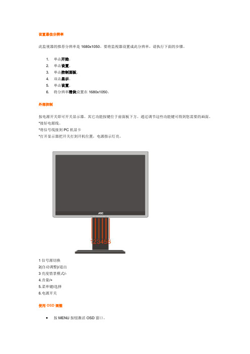
设置最佳分辨率此监视器的推荐分辨率是1680x1050。
要将监视器设置成此分辨率,请执行下面的步骤。
1. 单击开始。
2. 单击设置。
3. 单击控制面板。
4. 双击显示。
5. 单击设置。
6. 将分辨率滑块设置在1680x1050。
外部控制按电源开关即可开关显示器。
其它功能按键位于前面板下方。
通过调节这些功能键可得到您需要的画面。
*接好电源线。
*将信号线接到PC机显卡*打开显示器把开关打到开机位置,电源指示灯亮。
1信号源切换2(自动调整)/退出3亮度情景模式/-4.音量/+5.菜单键/选择6.电源开关使用OSD调整∙按MENU按钮激活OSD窗口。
∙按-或+浏览这些功能。
如果想要调整的功能突出显示,按MENU按钮激活它。
如果所选的功能包含有子菜单,再单击-或+可以浏览到子菜单功能。
如果想要调整的功能突出显示,按MENU按钮激活它。
∙按-或+更改所选功能的设置。
要退出和保存,请选择退出功能。
∙如果您想调整其它任何功能,请重复步骤2-3。
∙OSD锁定功能:要锁定OSD,请在显示器关闭时按住菜单按钮,然后按电源按钮打开显示器。
要解锁OSD,请在显示器关闭时按住菜单按钮,然后按电源按钮打开显示器。
∙亮度情景模式快捷键:当没有OSD菜单时,连续按Eco快捷键可选择不同的亮度情景模式(部分机型可能不适用).∙音量快捷键:当没有OSD菜单时,按音量快捷键(+)激活音量调整菜单,按-或+调节音量大小(仅针对带喇叭机型)∙信号源快捷键:当没有OSD菜单时,按信号源快捷键激活信号源功能(仅针两种输入信号及以上机型),连续按source键来选择信息栏中显示的信号源,按menu/enter键调整为选择的信号源。
∙自动调整快捷键:当没有OSD菜单时,按自动调整快捷键可启动自动调整功能DCB活彩技术调整什么是活彩技术?活彩技术(DCB)是一种高端色彩调节技术,它通过对RGB信号的解析而创造出更加生动自然的画面,以适应不同的环境需求。
ZWIN-PVOC06(固定) VOC在线监测仪产品说明书+附件-D03-4001-C00 RevC RAE

2
天津智易时代科技发展有限公司 Tianjin Zwinsoft Technology Co., Ltd
型号 B
1.2 原理介绍
仪器内部结构图
PID 是一种光离子化检测器,主要用来检测浓度在
1ppb-15000ppm 数量级的低浓度挥发性有机化合物和其它的有毒气
体。PID 是一个高度灵敏、适用范围广泛的检测器。
三、仪器操作、校准及维护.................................................................. 16 四、 故障处理........................................................................................ 17很高的时 间、空间分辨能力和探测灵敏度;
天津市西青区海泰发展六道海泰绿色产业基地 K1-5-602
6
天津智易时代科技发展有限公司 Tianjin Zwinsoft Technology Co., Ltd
5)先进的配套软件:采用数据采集、分析及可视化软件,大大 提高监测效率。
9)超宽测量范围,量程自由设定:测量精度达到 ppb 级: 10)3G 开放式气路结构:使检测范围扩大 2 倍,响应时间加快 10s,免维护时间有效延长; 11)智能的温度和零点补偿算法:使仪器表现出更加优良的性 能; 12)可检测数千种气体:广谱性检测,内置气体库,方便用户 选择; 13)多种信号输出:可微调标准 4~20mA(三线制)、RS485 Modbus、 三级开关量输出(常开/常闭可选);
6)引领全球 PID 发展趋势:采用自主研发的、拥有多项国际专 利的第三代本安型 PID 传感器,响应时间更快,抗湿性能更强,测 量范围大;无需工具可实现传感器互换,支持离线标定;
产品中文简要使用及保养说明
产品中文简要使用及保养说明产品品牌:瑞典瑞典VACULEXVPL 真空吊具设备型号:VacuPowerLiftVacuPowerLift型真空吊具是一种智能化的轻巧敏感型起重产品,因此对负载重量的变化也比较敏感,所以若应用同一套吊具搬运额定重量以下系列的工件时,一般都需要重新调节其动态平衡以达到最佳搬运状态。
一、动态平衡的调节:1、将控制室旋钮以逆时针方向旋转到极限位置;状态:操纵杆开口逐渐变大,提升气管长度松弛至最长极限;2、将吸盘置于待搬运工件的重心;状态:由于吸力小于工件重力,工件不能被提升;3、将控制室旋钮以顺时针方向缓慢旋转;状态:操纵杆开口逐渐变小,提升气管长度逐渐收缩;4、继续顺时针方向旋转控制室选钮,达到动态平衡后停止;状态:待搬运工件微微起伏,吸力与重力大致相等;5、再以逆时针方向旋转控制室旋钮,至吸力略小于重力;状态:待搬运工件由于重力大于吸力而静止在工作台面上;经以上5步骤调节之后,待搬运工件与吊具之间的状态略处于动态平衡之下,此时对控制室操纵杆施加极为轻微的力气,即可轻易破坏此平衡,尝试一下,几十公斤的重物,你只需要用一根手指就可以轻松地提升起来了!二、正确的操作手势:左手握住控制室操纵杆另一侧的黑色辅助手柄,右手手心朝向控制室操纵杆一侧,并贴靠在该侧的黑色辅助手柄上,拇指置于辅助手柄上方,其余四指伸向下,并轻轻扣住控制室操纵杆下端。
1、负载提升时的手势:左手握住控制室操纵杆另一侧的黑色辅助手柄,右手中指轻轻向上拉动控制室操纵杆,负载被提升;2、负载搬运时的手势:左手握住控制室操纵杆另一侧的黑色辅助手柄,负载提升至适宜高度后始终以右手中指轻轻扣在控制室操纵杆上保持不动;3、负载降低时的手势:左手握住控制室操纵杆另一侧的黑色辅助手柄,右手中指翻至控制室操纵杆以上,并轻轻向下拨动控制室操纵杆,负载被降低;4、负载释放时的手势:左手握住控制室操纵杆另一侧的黑色辅助手柄,右手拇指从控制室一侧的辅助手柄上方用力向下按压控制室操纵杆至按不动为止,同时左手拉起控制室操纵杆另一侧的黑色辅助手柄,使吸盘的一侧轻轻翘起,真空被破坏,负载被释放。
室内VOC传感器+变送器+说明书-V3

4/7
电气接线
三线制电流型接线示意图 电流输出接线定义: 6 口,P+与电源正极连接。 5 口,P-与电源负极连接。 4 口,空。 3 口,VOC 为信号输出端+。
室内 VOC 传感器/变送器
______ 说明书 ______
1/7
概述 空气质量传感器/变送器应用于空气质量的检测,适用于检测从建筑材
料、装修、家具、吸烟、烹饪、室外污染物挥发的有机化合物,如苯类、醇类、 醚类、脂肪烃类、醛类、胺类、酮类、芳香化合物、一氧化碳、甲烷、液化石 油气、有机酸等各种有机挥发性气体。
RS485 10~28VDC
5.0mm 间距,M2.5 钢螺丝,0.2Nm 扭矩,0.02 欧姆接触电阻 24~18AWG(0.2~1.0mm2),剥线长度 6-7mm
温度 0...+50℃
湿度 0...95%RH,无冷凝
温度 -20...+60℃
湿度 5-95%RH,无冷凝
ห้องสมุดไป่ตู้
IP30 参考 IEC 529 – 598/GB 700 – 86/ GB 4208
15 min
60s
标准校准
4~20mA 0~10VDC
RL<400 ohm RL>10k ohm
1C 或者 1O,可通过跳线帽选择常开常闭触点
Au+Ag Alloy
3A:120VAC/24VDC
RS485 串口输出
多点,半双工
2 线制,最大通讯距离 1200 米,端子直接连接
- 1、下载文档前请自行甄别文档内容的完整性,平台不提供额外的编辑、内容补充、找答案等附加服务。
- 2、"仅部分预览"的文档,不可在线预览部分如存在完整性等问题,可反馈申请退款(可完整预览的文档不适用该条件!)。
- 3、如文档侵犯您的权益,请联系客服反馈,我们会尽快为您处理(人工客服工作时间:9:00-18:30)。
Select Big Square Shafts Of Appropriate Length (shafts Shall Have A Length Which Will Have 2-4cm Left Outside Two Faces Of The Door When The Lock Body Is Inserted)
4.2 Insert The Square Shaft
Indoor
Outdoor
2-4cm
2-4cm
Indoor
insert it with the small head facing outward
Outdoor
insert it with the small head facing lock body
Selection And Adjustment Of Opening Direction 3
3 Adjust smart lock
3.1 Adjust Latch Bolt latch bolt strike plate
1.Push The “latch Bolt Strike Plate”up To The Top. 2.Push The Latch Bolt In And Rotate It 180°;
connecting bolt
Installation Slot
set screw
the installation slot shall be placed vertical.
1.Screw In Two Connecting Bolts Into The Outer Panel.
2.Then Insert The 4x4 Mechanical Key Small Square Shaft And Tighten The Small Square Shaft With Set Screws (it Will Be Appropriate When The Small Shaft Can Be Inserted Into The Lock Body For 1-2cm;cut It If It,s Too Long)
6 3 10 8
1
2 4
5
6
3
7 2
安 装 爆 炸 图 (爆炸图只做参考) Exploded Drawing For Installation(for Reference Only)
1.外面板(1只) 2.连接螺栓(2根) 3.方轴压簧(2根) 4.锁体固定螺丝(4枚) 5.锁体(1个) 6.大方轴(2根) 7.小方轴(1根) 8.内面板(1只) 9.电池盖板(1片) 10.内外面板连接螺丝(2枚) 11.电池
1.Outer Panel X1 2.Connecting Bolt X2 3.Pressure Spring Of Square Shafts X2 4.Lock Body Set Screw X4 5.Lock Body X1 6.Big Square Shaft X2 7Small Square Shaft X1 8.Inner Panel X1 9.Battery Cover X1 10.Coupling Screw For Inner And Outer Panels X2 11.Battery
How To Install Your Smart Lock How To Use The Fingerprint Password Lock
How To Use Your Password Card Lock Advanced Features And Emergency Application
ENGLISH PG 1-171 Nhomakorabea9
No.5 Battery
4
Configuration List 2
INSTALLATION OF VOC SMART LOCK
1 Judgment Of Door Opening Direction
Judge Opening Direction Of Your Door In Accordance With The Following Diagram.
select the panel with a right-hand handle
fixed angle screw facing indoor bevel facing outdoor
V - SERIES
opening outward to the right
select the panel with a right-hand handle
Thenpull The Latch Bolt Out. 3.Push The”latch Bolt Strike Plate”down To The Bottom. 3.2 Locating Screw
fixed angle screw
There Is Only One Fixed Angle Screw,and This Hex Head Screw Must Be Installed On The Side Of The Inner Panel.
Installation Procedures 5
Insert Front Panel Connection Line Of Lock Body Into The Interfacd On The Front Panel
滑盖 Sliding Cover
SMARTLOCK www.voc.so
OPEN BATTERY
保险旋钮 Safety Knob
V - SERIES
滑盖 Sliding Cover
触摸密码区 Touch Screen For Password 高清显示屏 High Definition Screen 指纹采集区 Fingerprint Capturing Area
Turn The Handle To Check Whether It’s Securely Fixed.
Selection And Adjustment Of Lock Body 4
4 Installation of Smart Lock
4.1 Installation Lock Body
Place The Lock Body Into The Door Leaf Processed To The Specified Dimension Pull The Connection Lines Of Lock Body Inner And Outer Panels Through The Two Sides Of The Door In Accordance With Indications On The Tag.
简体中文 PG 18-34
中国
한국 Sweden Edition: V2.1
English
CONFIGURATION LIST
When Unpacking,please Check Carefully In Accordance With The List.if Anything Is Missing, Please Ask Ask Us Or Our Agents For It.
V - SERIES
opening outward to the left
fixed angle screw facing indoor
select the panel with a left-hand handle
V - SERIES
opening inward to the right
bevel facing outdoor
3.3 Adjust The Handle
180°
V - SERIES V - SERIES
Unscrew The Handle Set Screw With A M4 Socket Head Wrench
Pull The Handle Out Moderately And Rotate It 180 To The Right Position Tighten The Handle Set Screw.
opening outward to the left
opening inward to the left
opening outward to the right
opening inward to the right
2 Selection Of Smart Lock
This Smart Lock Features The Function Fo Four Directions Integrated Into One And Can Be Used On Doors Opening Outward To The Right,opening Inward To The Right,opening Outward To The Left And Opening Inward To The Left With Proper Adjustment.
fixed angle screw facing indoor
V - SERIES
opening inward to the left
bevel facing outdoor
select the panel with a left-hand handle
fixed angle screw facing indoor bevel facing outdoor
Insert The Big Square Shafts With Them Facing The Correct Directions.
4.3 Install Outer Panel
pressure spring of square shaft
small square shaft connecting bolt
