LeicaTCSSP2激光共聚焦显微镜系统操作手册
徕卡激光测距仪使用说明书

徕卡激光测距仪使用说明书-CAL-FENGHAI.-(YICAI)-Company One1徕卡激光测距仪使用说明书一、使用前的准备(一)电池的装入/更换打开仪器尾部的固定挡板。
向前推卡钮,向下将底座取下。
按住红色的卡钮推开电池盒盖。
安装或更换电池。
关闭电池盒盖,安装底座和卡扣。
当电池的电压过低时,显示屏上将持续闪烁显示电池的标志{B,21}。
此时应及时更换电池。
1、按照极性正确装入电池。
2、使用碱性电池(建议不要使用充电电池)。
3、当长时间不使用仪器时,请取出电池,以避免电池的腐蚀。
更换电池后,设置和储存的值都保持不变。
(二)多功能底底座固定挡板可以在下面的测量情况下使用:1、从边缘测量,将固定挡板拉出,直到听到卡入的声音。
2、从角落测量,将固定挡板拉出,直到听到卡入的声音,轻轻将固定挡板向右推,此时固定挡板完全展开。
仪器自带的传感器将辨认出固定挡板的位置,并将自动设置测量其准点。
(三)内置的望远镜瞄准器在仪器的右部有一个内置的望远镜瞄准器。
此望远镜瞄准器为远距离测量起到辅助的作用。
通过瞄准器上的十字丝可以精确地观察到测量目标。
在30米以上的测量距离,激光点会显示在十字线的正中。
而在30米以下的测量距离,激光点不在十字线中间。
(四)气泡一体化的水泡使仪器更容易调平。
(五)键盘1、开/测量键2、第二级菜单功能3、加+键4、计时(延迟测量)键5、等于[=]键6、面积/体积键7、储存键8、测量基准边键9、清除/关键10、菜单键11、照明键12、间接测量(勾股定律)键13、减-键14、BLUETOOTH(六)显示屏1、关于错误测量的信息2、激光启动3、周长4、最大跟踪测量值5、最小跟踪测量值6、测量基准边7、调出储存值8、储存常数9、主显示10、单位,包括乘方立方(2/3)11、顶的面积12、墙面积13、3个额外显示(如:测量中间值)14、BLUETOOTH蓝牙开/关15、第二级菜单功能开16、硬件故障17、间接测量-利用勾股定律18、间接测量-利用勾股定律-部分高度19、面积/体积20、带常数的测量21、电池充电量显示二、菜单功能(一)设置在菜单中可以改变设置,并将其长久保存,并在关机和更换电池后不改变。
Leica共聚焦操作快速流程
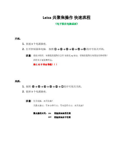
Leica共聚焦操作快速流程(电子版在电脑桌面)开机:1.接通3 个电源插座;2.打开控制器和电脑:按照①→ ②→ ③→ ④→ ⑤→ ⑥的序号依次开机;注意:系统开机时,显微镜的载物台会作初始化 xy 移动,请确保载物台周围没有障碍物!此时也不要放置样品;禁止用手转动物镜!!!关机:1.按照⑥→ ⑤→ ④→ ③→ ②→ ①的序号依次关机;2.拔掉3个电源插座;注意:先关电脑,再关仪器!关激光器后,等5分钟左右,等风扇停止后,再关电源!激光器的开关: ON 钥匙转到垂直位置OFF 钥匙转到水平位置软件快速操作:1.在桌面上,双击打开显微镜控制软件的图标“LAS AF ”:2.出现如下图标,直接点击“OK ”直接点击“ OK ”3.进入软件操作界面后,点击“Configuration ”(1),然后点击“Laser Config ”(2),再打开所需要的激光器开关“ON/OFF ”(3);1324.点击“Acquire ”;点击“SEQ ”125.选择物镜;注意:禁止用手转动物镜!!!选择物镜6.有多个染料需要多个通道时,点击“+ ”增加通道;7.比如:选中“Seq. 1 ”后,打开405激光器;选择探测器PMT 1;选择染料DAPI;2 138. 然后选中“ Seq. 2 ”后 , 打开488激光器 (不关Laser 405,激光强度调到0);选择探测器PMT 2;选择染料Alexa 488; 如果需要DIC 图像,则打开探测器“PMT Trans ”;注意: 探测器探测激发波长的范围 不能 与激光线重合!【 没有特殊需求,不要用“HyD 3”探测器!! 】123少用HyD3DIC激光强度为09.点击软件左下方的“Live”,进行图像预览;调节“Gain”增加探测器探测信号的灵敏度(一点蓝);调节“Offset”去背景(一片绿);注意: Gain值必须小于 800 !!这里可以结合增加激光强度和Gain值来调荧光信号。
激光共聚焦显微镜操作指南说明书
激光共聚焦显微镜操作指南说明书激光共聚焦显微镜(Laser Scanning Confocal Microscope)是一种高分辨率、高对比度的显微镜,广泛应用于生物医学研究、材料科学等领域。
本操作指南将详细介绍激光共聚焦显微镜的操作流程和基本操作技巧,帮助用户正确、高效地使用该设备。
一、设备准备在开始使用激光共聚焦显微镜前,需要进行以下设备准备:1. 检查电源线和数据线是否连接正常,确保设备供电和数据传输正常;2. 检查激光源是否正常工作,激光功率是否稳定;3. 检查镜头和滤光片是否清洁,清除灰尘和污渍,确保成像质量;4. 准备适当的标本样品,并将其固定在载玻片上。
二、系统启动1. 确保设备处于待机状态,按下电源按钮,等待系统启动;2. 检查系统软件是否正常运行,若出现异常情况,及时联系维修人员进行处理;3. 检查镜头和滤光片的安装是否正确,确保成像时的光路通畅;4. 开启激光源,根据需要选择合适的激光波长和功率;5. 调节扫描镜和物镜的位置,使光线准确聚焦在样品上。
三、图像获取1. 打开激光共聚焦显微镜软件,并根据需要选择合适的成像模式;2. 调节激光功率和增益,确保图像的亮度和对比度适宜;3. 调节扫描镜的扫描速度,根据样品的要求选择合适的扫描速度;4. 调节焦距和聚焦位置,通过手动或自动对焦功能获取清晰的图像;5. 点击图像捕捉按钮,记录当前图像或录制图像序列。
四、图像处理和分析1. 通过激光共聚焦显微镜软件提供的图像处理功能,对图像进行调整和增强,以获得更好的观察效果;2. 根据需要,利用软件提供的计算和分析功能对图像进行进一步处理,如三维重建、光学切片等;3. 对图像进行定量分析时,选择合适的工具和算法,并按照要求设定参数;4. 记录和保存处理后的图像数据,以备后续分析和报告撰写使用。
五、设备关闭1. 停止图像采集和处理工作;2. 降低激光功率,关闭激光源;3. 将扫描镜和物镜返回初始位置,关闭设备;4. 断开电源和数据线,保持设备清洁干燥。
激光共聚焦显微镜操作流程

激光共聚焦显微镜操作流程下载温馨提示:该文档是我店铺精心编制而成,希望大家下载以后,能够帮助大家解决实际的问题。
文档下载后可定制随意修改,请根据实际需要进行相应的调整和使用,谢谢!并且,本店铺为大家提供各种各样类型的实用资料,如教育随笔、日记赏析、句子摘抄、古诗大全、经典美文、话题作文、工作总结、词语解析、文案摘录、其他资料等等,如想了解不同资料格式和写法,敬请关注!Download tips: This document is carefully compiled by theeditor. I hope that after you download them,they can help yousolve practical problems. The document can be customized andmodified after downloading,please adjust and use it according toactual needs, thank you!In addition, our shop provides you with various types ofpractical materials,such as educational essays, diaryappreciation,sentence excerpts,ancient poems,classic articles,topic composition,work summary,word parsing,copy excerpts,other materials and so on,want to know different data formats andwriting methods,please pay attention!以下是激光共聚焦显微镜的一般操作流程:1. 样品制备根据实验要求,准备好待观察的样品。
LeicaSp2共聚焦操作手册
Leica TCS SP2 激光共聚焦显微镜系统操作手册一、荧光显微镜Leica DMRE的使用A:步距调节B:电动升台按钮C:电动降台按钮D:微调E:上限设置F:下限设置1、观察、扫描转换拉杆2、卤素灯开关3、透射光探测器开光横档4、荧光光路开关5、荧光滤镜转盘1:DAPI;2:TRITC;3:FITC;4:SCAN6、镜头侧DIC棱镜转盘7、与镜头相配DIC滤块8、起偏器9、检偏器10、镜头侧DIC棱镜微调旋钮11、光强调节纽12、减光滤光片13、孔径光阑14、视场光阑选择合适的镜头Leica TCS SP2 镜头配置镜头类型使用介质放大倍率/数值孔径编号HC PL APO CS DRY 10X /0.4 506511HC PL APO CS DRY 20X/ 0.7 506513HC PL APO CS DRY 40 X 0.85/ CORR 506140HC PL APO Ibd.BC OIL 63X /1.4 506192Leica TCS SP2 AOBS 镜头配置镜头类型使用介质放大倍率/数值孔径编号HC PL FLUOTAR DRY 10X/0.3 506505HC PL FLUOTAR DRY 20X/0.5 506503HCX PL APO OIL 40X/1.25-0.75 506176HC PL APO Ibd.BC OIL 63X/1.4 506192 HCX PL APO CS OIL 100X/1.40-0.70 506038 WATER HCX APO L U-V-I WA TER 63X/0.9 506148荧光观察荧光光路开关至“O”位,转轮至“1.0×”位,转换拉杆完全推进,荧光滤块换到相应号位(1:DAPI;2:TRITC;3:FITC;4:SCAN)图像输出扫描荧光光路开关至“I”位,转轮至“UV”位,转换拉杆完全拉出,荧光滤块换到4:SCAN)荧光观察(以油镜观察为例)1、样品正面朝上正确放在显微镜样品台上,点上镜油。
Leica激光扫描共聚焦显微镜快速操作手册

2
7
1 6
3 4
5
1 研究级显微镜 2 扫描头
8
10
9
11
3 防震台 4 EL6000荧光激发光源 5 显微镜控制器
6 遥控手轮
12 13
7 显示器 8 控制面板 9 键盘
10 电脑鼠标
14
11 电脑桌
12 CSU 13 电源控制 14 电脑主机
Leica TCS SP8正置,配备紧凑型光源组件(CSU)
物镜选择按钮 预览按钮 Live 拍摄按钮 叠加图像显示按钮,在使用两个或以上数量通道拍摄多色图像时,用于显示 所有通道叠加后的图像
7
2.3 在显微镜下观察样品
2.3.1 选择物镜:可通过显微镜主机右侧的物镜转换按钮,或软件中的“Objectives” 键进行选择。(如下图)(注意:有时,显微镜主机上的物镜转换按钮不能在干镜 和油镜或水镜之间切换,软件中都可以切换)
2
Leica TCS SP8基本系统组成
1 2
3 4
7 6
5
Leica TCS SP8倒置,配备灵活型光源组件(FSU)
8
9
10 11
13 12
14
1 研究级显微镜 2 扫描头 3 防震台 4 EL6000荧光激发光源 5 显微镜控制器 6 遥控手轮 7 显示器 8 控制面板 9 键盘 10 电脑鼠标 11 电脑桌 12 FSU 12.1 开机顺序 (硬件标号请参考前面的系统组成图)
(1)因为 FSU 和 CSU 硬件的电源控制 )不同,请分别按照如下步骤开机:
FSU 系统
CSU 系统
依次打开“PC Microscope”、“Scanner Power”、 先按电脑主机上的电源按钮启动电脑,再打
Leica激光共聚焦显微镜 操作规程
潍坊医学院医学研究实验中心仪器简明操作规程汇编
激光共聚焦显微镜简明操作规程
1. 启动
开启UPS电源,依次开启右侧手柄上的三个开关,从左至右顺序开启,最后开启激光钥匙。
2. 开启软件
电脑进入操作系统界面后,双击电脑桌面启动共聚焦操作软件。
3. 自检
点击对话框的“OK”键进行自检,结束后进入软件界面
4. 开启激光管
点击屏幕上方的“configuration”按钮进入配置界面→点击左边
按钮→打开所需激光(OFF →ON ),Argon激光还需拖动右方滑块以调节输出功率
5. 设置参数
6. 放置样品进行观察。
7. 观察结束保持数据。
8.关机,做好记录。
激光共聚焦扫描显微镜操作规程
激光共聚焦扫描显微镜操作规程一.开机程序1.开启总电源,确认所有仪器电源状态正常工作2.开启电脑,双击桌面上的LSM510图标,开启显微镜。
3.在初始平面上点击Start Expert Mode 键开启专家拍摄模式。
4.在主菜单中点击File New键,建立新的数据库。
二.软件拍摄1.在主菜单上点击Acquire Laser键,开启需要使用的激光2.在主菜单上点击VIS键,开启显微镜观察模式3.把需要观察的玻片放到载物台上选择需要观察的平面4.在主菜单上点击LSM键,开启进入显微镜激光扫描模式5.在主菜单上点击Config键,选择所需要扫描的模式及参数6.在主菜单上点击Scan Find键,进行图像参数自动校正7.在Scan子菜单下点击Fast X键,进行层面选择8.在连续扫描中调节放大器增益、补偿;激光强度等图像参数来优化图像9.点击图像子菜单上的Save键存储优化好的图像三.关机程序1.完成所有操作后,关掉激光开关,冷却5分钟后,点击主菜单上Exit键,退出所有程序2.关闭电脑3.关闭电源ZEISS 510 MET A二维扫描程序1.在Acquire → config →确定扫描所需的波长,(如果已作过相同方法的扫描,可直接调出一张相同条件的图像,用图像窗中的Reuse确定有关的扫描条件)2.在Acquire → micro →在低倍镜(透射光或荧光)下找到要观察的图像3.在Scan control → mode → find →在显示器上找到图像,选定扫描需用的分辨率4.调节物镜到适当的放大倍数5.Scan control → mode →New,打开一新图像窗6.在Scan control → mode → cont →用zoom将图像大小调至最佳,用Pinhole(一般选1)、Detector Gain(650左右,不宜时间超过800,也不宜低于500)、Amplifier offset(不宜过低),以及选择作算术平均值次数、调节激光强度(488nm不超过25%)等调节图像质量至最佳。
Leica TCS SPE共聚焦显微镜操作规程(1)

Living up to Life
Page 9
共聚焦——三维层切
1. 单击 Live进行预览,调至合适的 焦平面,再调节激光强度、接收 范围、PMT Gain和Offset等参数 2. 单击Set Plane记录焦平面位置
Living up to Life
3. 继续预览,改变 z 轴层面以确定 层切的起点和终点,红色表示已 设定
开软件
1. 系统进行自检,在此过 程中不要触碰显微镜 2. 自 检 完 毕 之后 ,显 示 LAS AF基本界面
Living up to Life
在显微镜下观察样品
1. 选择合适的物镜 2. 将样品放置于载物台上,盖玻片 一侧靠近物镜 3. 在明场下观察样品。调节载物台 xy 手柄 及 调焦旋钮,寻找合适的 焦平面及视野
4. 采用系统优化值;也可单击 Nr. of steps 设置层切数, 或层切间距 5. 设置扫描分辨率、速度和平 滑次数 6. 单击Start按键开始三维层切
Page 10
共聚焦——时间序列扫描
1. 选择xyt模式 2. 单击 Live 进行预览,调至合适的焦 平面,再调节激光强度、接收范 围、PMT Gain和Offset等参数 3. 停止预览 4. 设置采图的 时间间隔 ,也可选择 Minimize 5. 选择时间模式 1) 连续采图直至手动停止 2) 设置采集总时间 3) 设置采集帧数 6. 按回车键或单击 Apply 记录上述设 置 7. 单击Start按键进行时间序列扫描
Living up to Life
2. 设置扫描速度 (Speed)
3. 设置平滑次数 (Frame Aveage 按键 进行图 像采集
Page 8
共聚焦——多通道采集
激光共聚焦显微镜操作规程
激光共聚焦显微镜操作规程一、准备工作a)打开计算机。
依次打开激光器电源、钥匙开关。
多线氩离子(458 nm, 488 nm, 514 nm) ON、氦氖绿(543 nm) ON、氦氖红(633 nm) ON。
打开汞灯电源开关。
b)登陆Windows XP系统。
双击快捷方式:FV10-ASW 1.1。
User ID: Administrator ; Passeword: Administrator。
注意区分大小写。
二、显微镜镜下观察1.微分干涉差观察a)使用手控面板选择物镜。
插入起偏镜。
插入微分干涉滑块。
b)点击FV10-ASW软件中的图标。
标本聚焦.2.荧光观察:c)使用手控面板选择物镜。
d)打开汞灯的机械快门,拉出DIC滑块,点击FV10-ASW软件中的图标e)使用手控面板选择荧光滤色片。
标本聚焦。
3.获取单张荧光图像a)点击FV10-ASW软件中的按钮。
b)关闭汞灯快门,点击按钮,关闭卤素灯快门。
c)点击染料选择按钮,在染料列表中,双击用于观察的荧光染料。
点击Apply按钮。
d)点击XY Repeat按钮开始扫描。
调节图像。
点击Stop按钮停止扫描。
e)选择AutoHV,,并选择扫描速度。
f)点击XY按钮取得一幅图像。
g)点击SeriesDone按钮,“2D View-LiveImage(x)”2D界面就出现。
h)保存该幅图像:右图像管理器中显示的图像图标,选择另存为保存该幅图像。
(保存为“xml”类型是击FV10-ASW软件专用的图像格式。
)4.获得单张(荧光+微分干涉)图像a)点击FV10-ASW软件中的按钮,关闭汞灯快门。
点击按钮,关闭卤素灯快门。
b)点击染料选择按钮,在染料列表中,双击用于观察的荧光染料。
点击Apply按钮。
c)选择TD1。
d)点击XY Repeat按钮开始扫描。
调节绿色(FITC)图像和微分干涉差的图像。
点击Stop按钮停止扫描。
e)选择AutoHV, 并选择扫描速度。
leica共聚焦显微镜使用说明

Leica共聚焦显微镜使用说明Step 1: 打开PC电源——“1”Step 2: 打开汞灯控制开关——“2”Step 3: 打开中控盒——“3”Step 4: 打开计算机主机——“4”,启动计算机。
注:计算机操作系统启动后方可继续开机!!Step 5: 顺序打开激光器电源Scanner—“5”,激光冷却系统LASER Ar/ArKr—“6”★注:须确认冷风开启后方可打开激光电源!!!!!Step 6: 将上图虚线框中激光功率控制旋钮——“6.5”顺时针旋转60°左右。
Step 7: 将上图所示488 nm激光管开关——“7”钥匙沿顺时针旋转约120°至显示灯亮,再将钥匙旋回竖直位置Step 8: 依次将上图所示543/594 nm激光管开关——“8”和633 nm 激光管开关——“9”钥匙沿顺时针旋转约90°至显示灯亮。
Step 9:依次打开半导体激光器电源——“10”和405 nm激光管开关——“11”,(“11”的开启方式同“8”、“9”。
)Leica共聚焦显微镜关机顺序及注意事项Step 1: 关闭软件→拷贝Data→关闭计算机Step 2: 依照开机顺序倒序关闭各个开关,由”11”→”7”, ”5”→”1”。
★注:(1)冷风——”6”不能立即关闭!!须在关闭所有硬件设备30min 后方可关闭,以使激光管完全冷却,延长使用寿命。
(2)PC电源——“1”须在电脑确定关闭后方可关闭!!数据采集Step 1: 实验前扫描样本片观察激光通路是否正常工作。
Step 2: 上样,须轻起轻落科勒照明系统,选择合适倍数物镜,通过FLUO键选择相应荧光通道,调节载物台和焦距,找到合适视野。
Step 3: 点击由Visual→Scan,点击选择扫描模式,如xy, xyz, xyt, xyzt, xyλ etc..点击选择扫描格式(一般为默认值512*512)。
Step 4: 点击打开Beam path setting窗口,对光路和检测器进行设置。
激光扫描共聚焦显微镜操作指南说明书
激光扫描共聚焦显微镜操作指南说明书[激光扫描共聚焦显微镜操作指南说明书]引言:本操作指南为用户提供激光扫描共聚焦显微镜的详细操作流程及相关注意事项。
在使用本设备之前,请仔细阅读本指南,以确保能够正确、安全地操作设备,并获得最佳的成像效果。
一、设备介绍激光扫描共聚焦显微镜是一种先进的显微镜技术,结合了共聚焦成像和激光扫描技术,可以实现高分辨率、三维成像及活细胞观察等功能。
本设备由以下主要部分组成:1. 共聚焦显微镜主体:包括光源系统、光学系统、扫描系统、探测器等核心部件。
请勿对主体进行任何未经授权的拆卸或修改。
2. 控制系统:用于控制设备的开关、成像参数设置、图像采集及处理等功能。
在操作设备之前,请确保控制系统处于正常工作状态。
二、准备工作在操作激光扫描共聚焦显微镜之前,请进行以下准备工作:1. 检查设备:确保设备的电源线、信号线、光纤等连接线路良好,无损坏或松动情况。
2. 准备标本:根据需要观察的样本类型,准备适当的标本片,并在标本片上施加适当的荧光染料。
3. 调整镜片:根据需要选择适当的镜头,并按照设备说明进行安装和调整。
三、操作步骤以下为基本的操作流程,具体步骤可能会因设备型号和厂家而有所不同,请根据实际情况进行操作:1. 打开设备电源:将电源开关置于“开启”位置,待设备启动完全后,检查设备各部分是否正常。
2. 设置成像参数:通过控制系统,设置激光波长、放大倍数、成像模式等参数。
根据标本类型及观察需求,合理选择参数设置。
3. 校准镜片:根据设备说明书,进行扫描头和标本之间的焦距调整,保证成像过程中的清晰度和准确度。
4. 开启激光:根据标本需要,选择相应的激光波长,并逐一打开相应激光。
5. 定位标本:通过显微镜目镜进行初步观察,调整位置和焦距,使标本位于成像区域。
6. 开始扫描成像:在控制系统中选择扫描图像模式,点击“开始扫描”按钮,启动扫描成像过程。
7. 图像采集和处理:根据需要,可设置图像采集的帧数、分辨率等参数,并在采集图像后进行必要的图像处理和分析。
激光扫描共聚焦显微镜操作说明书

激光扫描共聚焦显微镜操作说明书操作说明书激光扫描共聚焦显微镜是一种高端的显微镜设备,具有高分辨率、高灵敏度的特点,广泛用于生物学、医学、材料科学等领域。
为了正确且有效地操作激光扫描共聚焦显微镜,本操作说明书将为您提供详细的指导。
一、设备介绍激光扫描共聚焦显微镜由以下主要部分组成:1. 显微镜主体:负责接收样本的光信号,并进行扫描成像。
2. 激光系统:提供高能量、高稳定性的激光光源,用于激发样本的荧光信号。
3. 探测系统:用于接收样本的荧光信号,并将其转化为图像信号。
4. 控制系统:提供对显微镜参数进行调节和设置的功能。
二、注意事项在操作激光扫描共聚焦显微镜之前,请确保您已熟悉以下注意事项:1. 安全操作:激光光源具有较强的激光辐射,请佩戴适当的激光防护眼镜并避免直接暴露于激光光束下。
2. 样本准备:样本应事先处理好并放置在适当的载玻片上,确保样本表面平整,避免气泡或杂质的干扰。
3. 导入样本:轻轻将载玻片插入显微镜主体的样本台中,并用调节旋钮精确定位样本。
4. 参数设置:根据实验需要,设置合适的激光功率、放大倍数和扫描速度等参数,确保获得清晰的图像。
5. 镜头清洁:定期清洁显微镜镜片,避免灰尘或污渍影响成像质量。
注意使用专用的镜头清洁纸和清洁液。
三、操作步骤基于激光扫描共聚焦显微镜的特点,以下为一般操作步骤的指导:1. 打开设备电源,等待设备启动并进行自检。
2. 调节放大倍数:通过显微镜主体上的放大调节旋钮,调节适当的放大倍数,以便观察到合适大小的图像。
3. 确定激光功率:在控制系统中,设置合适的激光功率以激发样本的荧光信号,避免过高的功率导致样本损伤。
4. 调整扫描速度:通过控制系统中的扫描速度调节器,设置合适的扫描速度,以获得清晰且稳定的图像。
5. 对焦样本:使用显微镜主体上的对焦调节旋钮,将样本调焦至最清晰状态。
6. 开始扫描:通过控制系统中的扫描启动按钮,启动扫描功能,并观察图像显示区域是否居中和清晰。
confocal instructions激光共聚焦显微镜教程
University of GuelphCollege of Biological ScienceConfocal Laser Scanning Microscope Instruction(Version 2; 2004.2)ContentsLeica TCS SP2 (2)Sign-up procedure for CLSM on WebCT............................................. (3)Common questions (4)5 Startup......................................................................................... ......... Shutdown. (6)Leica DMR Microscope: general information & care (7)Microscope settingOutward & Koehler illumination setting (9)I: bright field, epifluorescence & laser (all lenses) (10)II: DIC, epifluorescence & laser (63x & 100x lenses) (11)III: Phase contrast, epifluorescence & laser (40x lens) (12)Leica Confocal Software operationAcquisition Dialog Window (13)(Tables for Lens, Format, and Zoom…………...…………… 14)3D Image (18)(Switching z-scan mode; Galvo and Z-wide………………... 18)(When specimens are low signal or bleach sensitive……. 19)Datahandling (20)File types (20)I. Experiment overview window (20)II. Saving Images (21)III. Saving an image from viewer as a hard copy (21)IV. Saving an image as an animation file (21)University of GuelphCollege of Biological Science Confocal Laser Scanning Microscope- Leica TCS SP2 -1. Filter free SP head: a spectrophotometer for each detector channel: design your own filters, maximizesensitivity, minimize crosstalk, record emission spectra.2. Microscope: Upright microscope, Leica DMRo Lenses: 10x, 20x, 40x (Oil, Ph), 63x (Oil, DIC), 100x (Oil, DIC)3. Laser system:o Ar (50 mW): 458 nm, 476 nm, 488 nm, 514 nmo GreenHeNe (1.2 mW): 543 nmo RedHeNe (10 mW): 633 nm4. Two detection channels for fluorescence5. Transmitted light detection6. Leica confocal software (Version 2.5.1227a) for 2 D and 3 D image, ROI scanning, and time courseimaging.7. Simulator for processing images:o Leica confocal softwareo Adobe Photoshop Version 6.0o Office 20008. CD Writer9. Networked in Cbssrv workgroup.Contact: Dr. Michaela Strueder-KypkeOffice: room 208A, Axelrod Bldg.Tel: (519) 824-4120 ext. 52737Fax: (519) 767-1991(c/o the Botany Department)E-mail: confocal@uoguelph.caSign-up Procedure for CLSM on WebCT1. Go to “http://courselink.uoguelph.ca”2. Click on WebCT “Login” button and enter Name and Password inthe appropriate space.3. Under “Courses” heading myWebCT page, click on “LeicaConfocal Laser Scanning Microscope”.4. On the home page, click on “Calendar”.5. Select the month you want to use the microscope.6. Click the day you want to use the microscope.7. You will see the schedule for that day including other sign upsand times. If you click “View Week”, you will see the schedule forthe week.8. If you would like to book a time, go to “Add entry”9. Type your name in “Summary” box. Select your Start and Endtimes in the bottom columns. Keep access level “Public”.- Add in the “Detail” box which lasers you intend to use (Ar,GreenHeNe, HeNe).- If you wish to use the secondary computer for your imageprocessing, please type “Simulator” beside your name in the“Summary” box.C OMMON QUESTIONS:1. Why do I not see anything though eyepieces?- Did you pull out transmitted light detector?2. Why do I not see anything in Laser Mode?- Did you pull out Switch rod?- Did you set Fluorescent filter to 4 (scan)?3. Why is intensity very low in laser mode?- Did you pull out analyzer of DIC?- Did you open lens aperture (40x, 63x, 100x)?Confocal Laser Scanning Microscope Instructions StartupStart-upin order:1. UV lamp: ON [warm up for 10 min] *2. Microscope Main Switch: ON3. Laser fan button: ON (→ check for air that comes from cooling fan behind the door.)4. Scanner power button: ON [wait for 20 sec before starting software]5. PC power button: ON6. Ar/ArKr laser key: ON [warm up for 30 min, best after 1 hr]*7. GreenHeNe laser key: ON [warm up for 15 min]*8. HeNe key: ON [warm up for 15 min]*9. Windows NT login: Ctrl+Alt+Delete- Network: check “Workstation Only”- PC: login name**, TCS_User [password is NOT required]10. Leica Confocal software: start → PersonalAdditional Information*: You can use immediately after the switches are on, but you will not get the best performance of the lasers and UV lamp.**: Each laboratory will be given its own login name and a password.ShutdownShut down in order:1. Ar/ArKr laser key: OFF (start to count for 15 min)2. GreenHeNe key: OFF3. HeNe keys: OFF4. Leica Confocal Software: close5. Scanner power button: OFF< Make a backup CD of your data by “Easy CD creator” >6. Windows: shut down → wait for the message “It is now safe to turn off your computer”7. PC power button: OFF< Lens Cleaning >8. Microscope: OFF9. UV lamp: OFF10. Wait for 15 min (after Ar key OFF) till air from fan is cooled →Laser button: OFFIMPORTANT!- If somebody will use the microscope within 2 hr after you, do not turn OFF the Ar/ArKr laser key(1), Laser button (10), and UV lamp. All the other units should be shut down.- The Mercury lamp of the epifluorescence cannot be restarted within 30 min after use.- Back up your files on CD. Do not leave the files in the workstation.Leica DMR Microscope: General Information & CareLenses:ObjCond Obj Cond Obj Cond 10x ---with & without BFH------------3 – 420x --- 0.17 (1.5) BF H --- --- --- --- 1.2 – 1.3 40x OIL 0.17 (1.5) BFH------H30.4 – 0.563x OIL 0.17 (1.5) BF H D 63 --- --- 0.3 – 0.4 100x OIL0.17 (1.5)BF H D 100 --- --- 0.3 – 0.4Immersion oil:Use only the immersion oil provided with the microscope. Do not mix the immersion oil with other substances including immersion oil from another source. Remove with Windex any oil remaining on the cover slip used in previous observations with a different microscope.Cover slip:Sealing coverslip completely with nail polish or other sealing materials is highly recommended. This prevents mixing of immersion oil and embedding materials, movement of the coverslip when moving the stage, and moving embedded materials during z-sectioning. Be sure that any nail polish is completely dried before mounting slide onto the stage.Lens care:After use, clean lenses only with lens paper. Do not use Kim Wipes, cloth, etc. Fold the paper, and hold both sides of the paper keeping the folded edge strait. Rub the folded edge back and forth over the lens surface. Change the place on the paper and rub until there is no longer evidence of oil on the paper.LensesImmer-sionCoverslip µm (#)Bright FieldDICPhase ContrastStep Size (µm)Galvo stage:Inside frame of the specimen holder is used for z-position setting. Treat it with great care and avoid from bumping it, especially the projecting part of the holder.Automotive stage:A: stepwidth at fine focusing (1=0.1 µm, 2=0.7 µm, 3=1.5 µm)B: motor drive – UP till upper thresholdC: motor drive – DOWND: focusing wheelE: upper thresholdF: lower thresholdTo carry out the following tasks:Set and delete a threshold: pressing and sustaining the E or F keys.Override an upper threshold: with the focusing wheel.Switch between fine and coarse stepwidth: pressing B and C keys, simultaneously.IMPORTANT!- Do not use automotive stage without upper threshold setting: the stage travels to the mechanical end-switch position, which damages the condenser, the objectives and the specimens.- Upper threshold is important for proper application of software (Galvo stage).Koehler illumination setting:1) Focusing image2) Open Aperture diaphragm (13)3) Close Field diaphragm (14)4) Adjust condenser height till the edge of the filter becomes sharp.5) Center Field diaphragm by screws under condenser.6) Open Field diaphragm (14) until it just disappears from the field of view.Microscope setting for:Bright Field (BF), and Epifluorescence (Ef) observations with eyepieces and laser mode• 10x, 20x, 40x, 63x, & 100x lensesBF Ef Laser1. Switch rod PUSH IN PUSH IN PULL OUT2. Halogen lamp switch ON ON ON3. Transmitted laser detector bar PUSH OUT PUSH IN PUSH IN4. Fluorescent light CLOSE (UP) OPEN (DOWN) CLOSE (UP)5. Reflector turret (Fluorescent filter)4 (scan)1, 2, or 3(UV, G, or B)4 (scan)6. Turret for objective side WallastonprismsBF - BF7. Condenser turret H - H8. Polarizer - - -9. Analyzer for DIC PULL OUT PULL OUT PULL OUT10. Fine adjustment of objective sideWallaston prisms- - -11. Illumination intensity control ADJUST MINIMIZE MINIMIZE12. ND filter OFF - -Microscope setting for:Differential Interference Contrast <Nomarski> (DIC) and Epifluorescence (Ef) observations with eyepieces and laser mode• 63x & 100x lenses1) Take out when either 100x objective with 2x zoom or 63x objective with 5x zoom is used.DIC EfLaser1. Switch rodPUSH IN PUSH IN PULL OUT 2. Halogen lamp switchON ON ON3. Transmitted laser detector bar PUSH OUT PUSH IN PUSH IN4. Fluorescent lightCLOSE (UP) OPEN (DOWN) CLOSE (UP) 5. Reflector turret (Fluorescent filter) 4 (scan)1, 2, or 3 (UV, G, or B)4 (scan)6. Turret for objective side Wallaston prismsD - D 1)7. Condenser turret 63 for 63x 100 for 100x- 63 for 63x 100 for 100x8. Polarizer IN - IN 9. Analyzer for DICPUSH INPULL OUTPULL OUT10. Fine adjustment of objective side Wallaston prismsADJUST - ADJUST 11. Illumination intensity control ADJUST MINIMIZEMINIMIZE12. ND filter OFF--Microscope setting for:Phase contrast (Ph), Epifluorescence (Ef)observation with eyepieces and laser mode• 40x lensPh EfLaser1. Switch rod PUSH IN PUSH IN PULL OUT2. Halogen lamp switch ON ON ON3. Transmitted laser detector bar PUSH OUT PUSH IN PUSH IN4. Fluorescent light CLOSE (UP) OPEN (DOWN) CLOSE (UP)5. Reflector turret (Fluorescent filter)4 (scan)1, 2, or 3(UV, G, or B)4 (scan)6. Turret for objective side WallastonprismsBF - BF7. Condenser turret 3 - 38. Polarizer OUT - OUT9. Analyzer for DIC PULL OUT PULL OUT PULL OUT10. Fine adjustment of objective sideWallaston prisms- - -11. Illumination intensity control ADJUST MINIMIZE MINIMIZE12. ND filter OFF - -Leica Confocal Software operation!Focus your sample after the software opens. The software calibrates the Galvo stage during initializing the scanner that causes the focus change.Acquisition Dialog Window1. Press the “Obj.” button and select the objective lens to be used in the open dialog window.Check objective lens every time you switch objectives.2. Press the “Beam” button and select a method in the open “Beam Path Setting”dialog window.A method is a set of hardware settings specifically identifying a certain acquisitiontechnique and a special type of preparation.It is always possible to define and store your own methods in addition to the factory-set methods.3. Press the “Mode” button and select the scan mode.xyz, xzy: spatial scan modext, xyt, xzt, xyzt: time scan modexyλ, xzλ: spectral scan mode4. Press “Format” button to select the scan format.Besides the numerical aperture of the objective and the excitation wavelength, the scanformat, together with the electronic zoom, determines in large part the spatial resolutionof the recorded data. (See Table 1)A structure can only be scanned without information loss if the smallest optically resolvabledistance (=lateral resolution) is scanned with about 2 to 3 raster points.Excitation at 543ObjectiveMagnificationNumerical Aperture Resolution (nm)Scan Format (# x #)Zoom Factors Scan fieldSize (mm)Voxel 1)Size (nm)(current raster distance)Resolution / Voxel Size 2)10 0.3 747 512 1 1500 2930 0.3 747 512 2 750 1465 0.5 747 512 4 375 732 1.0 747 512 6 250 488 1.5 747 512 8 188 366 2.0 10 0.3 747 1024 1 1500 1465 0.5 747 1024 2 750 732 1.0 747 1024 4 375 366 2.0 10 0.3 747 2048 1 1500 732 1.0 747 2048 2 750 366 2.0 10 0.3 747 4096 1 1500 366 2.0 20 0.5 434 512 1 750 1465 0.3 434 512 2 375 732 0.6 434 512 4 188 366 1.2 434 512 8 94 183 2.4 20 0.5 434 1024 1 750 732 0.6 434 1024 2 375 366 1.2 434 1024 4 188 183 2.4 20 0.5 434 2048 1 750 366 1.2 434 2048 2 375 183 2.4 40 1 217 512 1 375 732 0.3 217 512 2 188 366 0.6 217 512 4 94 183 1.2 217 512 6 63 122 1.8 217 512 8 47 92 2.4 40 1 217 1024 1 375 366 0.6 217 1024 2 188 183 1.2 217 1024 4 94 92 2.4 40 1 217 2048 1 375 183 1.2 217 2048 2 188 92 2.4 40 1 217 4096 1 375 92 2.4 63 1.32 – 0.6 165 512 1 238 465 0.4 165 512 2 119 232 0.7 165 512 4 60 116 1.4 165 512 6 40 77 2.1 63 1.32 – 0.6 165 1024 1 238 232 0.7 165 1024 2 119 116 1.4 165 1024 3 79 77 2.1 63 1.32 – 0.6 165 2048 1 238 116 1.4 165 2048 2 119 58 2.8 100 1.4 – 0.7 155 512 1 150 293 0.5 155 512 2 75 146 1.1 155 512 4 38 73 2.1 100 1.4 – 0.7 155 1024 1 150 146 1.1 155 1024 2 75 73 2.1 100 1.4 – 0.7 155 20481150 73 2.11) Volume and pixel ! Voxel2) Resolution / Voxel Size < 2 ! undersamplingResolution / Voxel Size > 3 ! oversamplingExcitation at 488ObjectiveScan Format (# x #)Zoom FactorsScan fieldSize (mm)Voxel 1)Size (nm)(current rasterdistance)Resolution / Voxel Size* Magnification Numerical ResolutionLateral resolution =Numerical aperture0.4 x λRaster point distance(= Scan Frequency) (= Voxel size)Format size Scan field size =10 0.3 651 512 1 1500 2930 0.2651 512 2 750 1465 0.4651 512 4 375 732 0.9651 512 6 250 488 1.3651 512 8 188 366 1.8651 512 10 150 293 2.2 10 0.3 651 1024 1 1500 1465 0.4651 1024 2 750 732 0.9651 1024 4 375 366 1.8651 1024 6 250 244 2.7 10 0.3 651 2048 1 1500 732 0.9651 2048 2 750 366 1.8651 2048 3 500 244 2.7 10 0.3 651 4096 1 1500 366 1.8651 4096 2 750 183 3.6 20 0.5 390 512 1 750 1465 0.3390 512 2 375 732 0.5390 512 4 188 366 1.1390 512 8 94 183 2.1 20 0.5 390 1024 1 750 732 0.5390 1024 2 375 366 1.1390 1024 4 188 183 2.1 20 0.5 390 2048 1 750 366 1.1390 2048 2 375 183 2.1 40 1 195 512 1 375 732 0.3195 512 2 188 366 0.5195 512 4 94 183 1.1195 512 6 63 122 1.6195 512 8 47 92 2.1 40 1 195 1024 1 375 366 0.5195 1024 2 188 183 1.1195 1024 4 94 92 2.1 40 1 195 2048 1 375 183 1.1195 2048 2 188 92 2.14096 1 375 92 2.1 40 1 19563 1.32 – 0.6 148 512 1 238 465 0.3148 512 2 119 232 0.6148 512 4 60 116 1.3148 512 6 40 77 1.9148 512 8 30 58 2.5 63 1.32 – 0.6 148 1024 1 238 232 0.6148 1024 2 119 116 1.3148 1024 3 79 77 1.9148 1024 4 60 58 2.5 63 1.32 – 0.6 148 2048 1 238 116 1.3148 2048 2 119 58 2.5 63 1.32 – 0.6 148 4096 1 238 58 2.5 100 1.4 – 0.7 139 512 1 150 293 0.5139 512 2 75 146 1.0139 512 4 38 73 1.9139 512 6 25 49 2.9 100 1.4 – 0.7 139 1024 1 150 146 1.0139 1024 2 75 73 1.9139 1024 3 50 49 2.9 100 1.4 – 0.7 139 2048 1 150 73 1.9139 2048 2 75 37 3.85. Press “Speed” button to select the scan speed.The higher the set scan speed, the shorter the dwell time of the laser point.The higher the scan format at a constant speed, the shorter the dwell time of the laser pointover a sampling point.Using a lower scan speed results in a better signal-noise ratio, but relatively long impact of the light on the specimen can bleach it photochemically.6. Press “Pinh” button to set the detection Pinhole. Click the Airy 1 button, the detection pinhole is set automatically to the optimum value of 1 Airy unit depending on the objective in use. In addition to the numerical aperture of the objective and the wavelength of the light, the detection pinhole also determines the thickness of the optical sections.The wider the diameter of the pinhole, the more light reaches the detector. The imagebecomes brighter but blurring from structures outside the focal plane will also appear in theimage, making it increasingly unfocussed. Increasing the diameter of the pinhole above 1 Airy unit is recommended only for detecting very weak signals.7. Press “Continuous” button to start the continuous scan.Use the control panel and its defined acquisition parameters which include:a. Z-positionb. Amplification factor of the selected detectorc. Zoom (See Table 1)8. Click “Signal” button for setting the Detectors: Gain value and Offset value.1) Stop scanning.2) Click the color look-up tables (Arrows) currently working.3) Select Glow Under and Over.4) Adjust Gain value using PMT Gain Dials on the panel box or sliders in the SignalWindow as blue color scatters a little. Blue color indicates the strongest signal.5) Adjust Offset value using PMT Offset Dials or sliders in the Signal Window asgreen color uniformly covers an image (Value shouldbe 0 or -1). If you are working with two detectors theratio of green color in the two views is adjusted to bethe same.Detectors set for eliminating “Cross-talk” arenow set.9. Stop the continuous scan by pressing the “Cont.”button.10. Press “Aver.” button to define the number ofsampling times (frame average).Large number of averaging reduces noisebut can cause fading.11. Press “Single Scan” button to get a single optical image.3D Image3. Turn “Z-Pos” Dial on Panel Box.4. Press the “Begin” button to define the starting position of the 3D series.5. Press the “End” button to define the end position of the 3D series.6. Stop the continuous scan by pressing the “Cont.” button.7. Press “Sect.” button to define the number of optical sections. Go to “Others” to set by option.Image Dim. z/y (mm): The height of the entire image stack betweenthe beginning and end points of the image series.# Sections: The number of configured sections.Step size (mm): The step size, i.e. distance between two sections.Calculate the number of sections / Unchanged the height of the image stack Enter the desired step size in the “Step Size” field.Then click the “Calculate” button next to the Step Size filed.Calculate the number of sections / Unchanged the number of sections:Enter the desired step size in the “Step Size” field.Then click the “Calculate” button next to the # of Sections field.Calculate the step width / Unchanged the height of the image stack:Enter the # of desired sections in the # Sections” field.Then click the “Calculate” button next to the # Sections filed.Switching z-scan Mode:1. Press “z-Scan” button and switch themode.2. Press “z Position” on Panel Box Setting DialogWindow to switch over the modes.Galvo Z-WideMinimum step width 0.04 µm0.1 µmMaximum drive distance 170 µm Maximum drive distance of stage (cm)Drive module Galvo stage Microscope side motor drive: StageCalculate the step width / Unchanged the number of sections:Enter the number of desired sections in the # Sections” field.Then click the “Calculate” button next to the Step Size filed8. Press “Series” button to create an image series.When working with specimens that are:Low signal Bleach-sensitive Detector Gain ↑Rise Scan time ↓ReduceLaser power ↑Rise↓ ReducePinhole ↑ OpenAveraging ↓ Reduce or no useScan Speed ↓ Slow (200)↑ Fast (800)Scan Format ↑ Avoid undersampling↑Avoid oversamplingZoom ↓Short intervalBeam expander ↑ Use small diameter (3)↓ Use large diameter (6) Accumulation + Useful(+ Useful)Data HandlingFile types used in this applicationExperiment (*.lei) A Leica-specific, binary data format. When the experiment isloaded, both the image data and the experiment settings areloaded.Annotation sheet (*.ano) A Leica-specific, binary data format. The elements on theannotation sheet, such as images, texts and graphic images,are each available as individual objects.Tiff files (*.tif) These are Leica image files in single and multi Tiff format.Experimental files in RGB-Tiff format can be loaded as well.I. Experiment Overview Dialog WindowIMPORTANT:Experiment Dialog Window shows files thatare temporarily stored on RAM memory.Experiment: Click the “New” button forcreating a new Viewer window, which createsa new experiment. An experiment is a file that consists of one or more individual images or image series. This allows you to keep several images, each record using different scan parameters, or edited versions of images in one experiment.File name: Unsaved directories are named as “Experiment #”.Active mark (red check): This mark shows a viewer currently activated. Activate viewer by clicking a viewer or the image file on the directory.Series #: A new Series file is added in a new experiment or a directory that contains an activated image each time you press the “Series” button.Image #: A new image file is created in a new experiment or a directory that contains an activate image each time you press the “Single Scan” button.Preview #: When you press “Cont.” button, an image file is created in a new experiment or a directory that contains an activated image or series file. When a “Preview file” is activated and you do a continuous scanning, the preview file will be overridden.CLSM INSTRUCTION Ver. 2; CBS; U of G II. Saving Images1. Activate a view you want to save.2. Click the “Save as” button to save the data of the current experiment (*.lei) or the current annotation(*.ano) sheet.3. When saving an experiment, a folder is created at the file level with the name of the experiment. Thisfolder then contains the description file (*.lei) for the experiment as well as the individual image files.The description file (*.lei) contains parameter settings and color information for each image belonging to the experiment.When saving an experiment, the new folder contains all images belonging to the directory. Make sure to delete unnecessary images.IMPORTANT: the original contents (*.lei, *.tif) in a folder need to be a set. Keep the file size within the memory size of a CD (i.e. 640 MB) for your backup.RECOMMENDED: save one original image (Series or Image) in one folder (one Experiment) in which the processed images (i.e. 3D images) can be contained.AMPLIFICATION OF EACH IMAGE: right click of the image in the Experiment Overview WindowIII. Saving an image from a viewer as a hard copy1. Right click on the viewer and select “Send to” then “Experiment”2. Select one from three types as follows:a. Selection (raw): send raw data of only selected image on a viewer. Additives onthe image such as scale bar, numbers and letters will not be sent.b. Selection (snapshot): send all information with additives on the selected image on aviewer.c. All (snapshot): send all images with additives in a viewer.3. Click “Save” button to save the change of the experiment.IMPORTANT: Display Zoom affects for “Snapshot”. Select “Auto” or “1 : 1” before images are sent.IV. Saving an image as an animation file1. Create a 3D image from an image series.All processed images are stored on RAM. Delete unnecessary images!2. Right click at a 3D image and select “Export”.3. Put file name and save as a file type [*.avi].4. Choose “uncompressed”.Page 21 of 21About WebCT | Help | Students | Faculty & Designers | Guests | Site MapNewsWelcome to Courselink -- the University's portal to on-campus courses using WebCT.To see a list of classes that use WebCT Click Here.Some users have reported a "Permission Error" or a Search Page () appearing when they click on "Login to WebCT" if this is the case see our FAQ by clicking HereIf you need to register for a class at the University of Guelph you should use Webadvisor .If you need information on Distance Education then you should consult Open Learning .See FAQ's for more helpContact WebCT Support(click to login to WebCT)WebCT Login Instructions q Courses That Use WebCT q Look for my Distance Educationcourseq Test My Browser Setup q Email Courseware Support q WebDAV Instructions (drag anddrop files and folders into your course files)q Enhancing On-campus Courses Through Web-based LearningAbout This Site | Copyright InformationCourselink At Guelphhttp://courselink.uoguelph.ca/ [2/26/2004 11:14:55 AM]。
激光扫描共聚焦显微镜操作流程详解

激光扫描共聚焦显微镜(laser scanning confocal microscope)激光扫描共聚焦显微镜(laser sea nning con focal microscope),英文简写LSCM,俗称con focal。
LSCM是一种高科技显微镜,属于最先进的细胞生物学分析仪器。
我们学院使用的是瑞士徕卡公司(Leica)的TCS SP5型号的LSCM。
使用流程1、登陆或5号楼606室公用电脑下载?激光共聚焦预约使用审核表?,打印并填写。
2、联系卢剑清(手机:)审核并签名。
3、持已签名的?激光共聚焦预约使用审核表? 至5号楼610室预约使用时间,及领取钥匙,联系人:窦凯飞(手机:。
4、在熟练使用者的指导下,进行实验。
5、实验结束,及时归还钥匙。
仪器构造和原理LSCM的根本结构主要包括荧光显微镜系统及样品台、激光发射器、扫描器、检测器、图像存储处理和输出设备、计算机控制系统。
激光光源:激光扫描束经照明针孔形成点光源,普通显微镜采用的自然光或灯光是一种场光源,标本上每一点的图像都会受到邻近点的衍射光或散射光的干扰。
而LSCM以激光为光源,激光具有单色性强、方向性好、高亮度、相干性好等优点,可以防止普通显微镜的缺点。
一般常用的气体激光器如氩(Ar)、氪(Kr)、氦(He)、氖(Ne)。
illu min ati ng pin hole (照明针孔):使激光经过照明针孔后形成点光源,点光源具有光源方向性强、发散小、亮度高、高度的空间和时间相干性以及平面偏振激发等独特的优点。
且与detector pinhole(探测器针孔)及焦平面形成共聚焦装置。
分光镜(BeamSplitter):点光源发出的光经分光镜反射后,通过物镜在样品聚焦。
对标本内焦平面上的每一点进行扫描,Focal plane (焦平面):激光点光源照射物体在焦平面处聚焦,激发荧光标记的样本发射荧光,形成焦点光斑。
该光斑经过物镜和分光镜等一系列装置的处理,分别在照明针孔及探测针孔两处聚焦。
徕卡共聚焦显微镜安全操作及保养规程
徕卡共聚焦显微镜安全操作及保养规程前言徕卡共聚焦显微镜是一种高级的显微镜,它广泛应用于生物医学研究、神经科学、纳米科学等领域。
而在使用过程中,我们需要重视安全操作和合理的保养方式,以保证设备的正常运行和寿命,同时防止在操作过程中出现意外。
下面将介绍徕卡共聚焦显微镜的安全操作和保养规程,希望能够对用户起到一定的指导作用。
安全操作规程1.在操作设备前应先熟悉设备的结构和性能,了解相关控制器的作用及操作方法。
2.在操作设备前应着装合适的工作服装,在操作过程中应戴手套、护目镜等个人防护装备。
3.在操作设备前,应先对设备进行全面的检查,确保每一个工作参数处于正常范围内。
4.在操作设备过程中,禁止发生喧哗、吸烟、喝食等不良行为,以免产生安全事故。
5.操作设备时请勿将手伸进任何机械运动的位置,以免造成损伤。
6.如果设备出现了异常情况,请立即停机,关闭设备并及时与专业人员联系以解决问题。
设备保养规程1.在使用设备过程中,应保持设备的清洁和干净,每天结束后应先清理设备表面和器材,定期对设备内部进行彻底的清理和消毒。
2.在使用过程中,应注意不要过度带入污物和灰尘,以免对设备镜头以及内部偏光产生影响。
3.在存放设备过程中,应注意避免潮湿、阳光直射以及温度骤变等不良环境,建议存放在干燥防潮的场所。
4.在设备操作完成后,应注意对设备进行适当的维护处理,及时更换、清洁相应器材,充分保证器材的寿命。
5.如果设备出现故障,请及时联系专业人员进行维护处理,不要在未掌握详细信息的情况下擅自进行维修。
总结徕卡共聚焦显微镜在科研和病理学领域有着广泛的应用,然而安全操作和正确的保养方法则是保证设备寿命的重要保障。
希望以上安全操作和保养规程能够对徕卡共聚焦显微镜的用户有所帮助,以免在使用过程中出现意外和影响设备运行寿命。
LeicaTCSSP2激光共聚焦显微镜系统操作手册
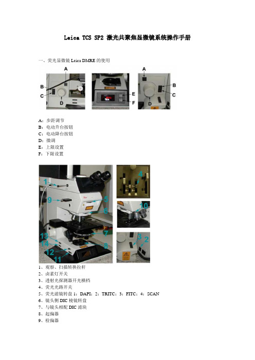
Leica TCS SP2 激光共聚焦显微镜系统操作手册一、荧光显微镜Leica DMRE的使用A:步距调节B:电动升台按钮C:电动降台按钮D:微调E:上限设置F:下限设置1、观察、扫描转换拉杆2、卤素灯开关3、透射光探测器开光横档4、荧光光路开关5、荧光滤镜转盘1:DAPI;2:TRITC;3:FITC;4:SCAN6、镜头侧DIC棱镜转盘7、与镜头相配DIC滤块8、起偏器9、检偏器10、镜头侧DIC棱镜微调旋钮11、光强调节纽12、减光滤光片13、孔径光阑14、视场光阑选择合适的镜头Leica TCS SP2 镜头配置镜头类型使用介质放大倍率/数值孔径编号HC PL APO CS DRY 10X /0.4 506511HC PL APO CS DRY 20X/ 0.7 506513HC PL APO CS DRY 40 X 0.85/ CORR 506140HC PL APO Ibd.BC OIL 63X /1.4 506192Leica TCS SP2 AOBS 镜头配置镜头类型使用介质放大倍率/数值孔径编号HC PL FLUOTAR DRY 10X/0.3 506505HC PL FLUOTAR DRY 20X/0.5 506503HCX PL APO OIL 40X/1.25-0.75 506176HC PL APO Ibd.BC OIL 63X/1.4 506192 HCX PL APO CS OIL 100X/1.40-0.70 506038 WATER HCX APO L U-V-I WA TER 63X/0.9 506148荧光观察荧光光路开关至“O”位,转轮至“1.0×”位,转换拉杆完全推进,荧光滤块换到相应号位(1:DAPI;2:TRITC;3:FITC;4:SCAN)图像输出扫描荧光光路开关至“I”位,转轮至“UV”位,转换拉杆完全拉出,荧光滤块换到4:SCAN)荧光观察(以油镜观察为例)1、样品正面朝上正确放在显微镜样品台上,点上镜油。
- 1、下载文档前请自行甄别文档内容的完整性,平台不提供额外的编辑、内容补充、找答案等附加服务。
- 2、"仅部分预览"的文档,不可在线预览部分如存在完整性等问题,可反馈申请退款(可完整预览的文档不适用该条件!)。
- 3、如文档侵犯您的权益,请联系客服反馈,我们会尽快为您处理(人工客服工作时间:9:00-18:30)。
Leica TCS SP2 激光共聚焦显微镜系统操作手册一、荧光显微镜Leica DMRE的使用A:步距调节B:电动升台按钮C:电动降台按钮D:微调E:上限设置F:下限设置1、观察、扫描转换拉杆2、卤素灯开关3、透射光探测器开光横档4、荧光光路开关5、荧光滤镜转盘1:DAPI;2:TRITC;3:FITC;4:SCAN6、镜头侧DIC棱镜转盘7、与镜头相配DIC滤块8、起偏器9、检偏器10、镜头侧DIC棱镜微调旋钮11、光强调节纽12、减光滤光片13、孔径光阑14、视场光阑选择合适的镜头Leica TCS SP2 镜头配置镜头类型使用介质放大倍率/数值孔径编号HC PL APO CS DRY 10X /0.4 506511HC PL APO CS DRY 20X/ 0.7 506513HC PL APO CS DRY 40 X 0.85/ CORR 506140HC PL APO Ibd.BC OIL 63X /1.4 506192Leica TCS SP2 AOBS 镜头配置镜头类型使用介质放大倍率/数值孔径编号HC PL FLUOTAR DRY 10X/0.3 506505HC PL FLUOTAR DRY 20X/0.5 506503HCX PL APO OIL 40X/1.25-0.75 506176HC PL APO Ibd.BC OIL 63X/1.4 506192 HCX PL APO CS OIL 100X/1.40-0.70 506038 WATER HCX APO L U-V-I WA TER 63X/0.9 506148荧光观察荧光光路开关至“O”位,转轮至“1.0×”位,转换拉杆完全推进,荧光滤块换到相应号位(1:DAPI;2:TRITC;3:FITC;4:SCAN)图像输出扫描荧光光路开关至“I”位,转轮至“UV”位,转换拉杆完全拉出,荧光滤块换到4:SCAN)荧光观察(以油镜观察为例)1、样品正面朝上正确放在显微镜样品台上,点上镜油。
2、长按电动升台按钮,使镜头和样品上镜油接触,调节微调旋钮,找到样品。
3、将光路转换成荧光观察位置,找到预扫描目标,将光路转换至扫描状态。
二、Leica LCS 软件的使用(一)、Leica confocal software 界面软件面板介绍左:TCS-menu:accquire view 3D process quantify application右:image windows(二)、设置参数打开软件,默认在Acquire面板中,mode扫描模式为xyz,Format扫描像素为512x512,average line/frame average 为1。
Mode 扫描模式:空间扫描模式:xyz xzy时间扫描模式:xt xyt xzt xyzt光谱扫描模式:xyλxzλFormat扫描像素一般设置为1024 x1024。
average line一般设为4或8。
(三)、软件具体的操作使用单荧光道扫描多荧光扫描DIC图像扫描荧光与DIC图像同时扫描多层扫描时间序列扫描光谱扫描ROI扫描FRETFRAPLIVE MODE多方法组合荧光强度分析单荧光扫描1、按Acquire按钮中的Beam键打开光路设置对话框窗口2、点击Mode选择扫描模式,如平面扫面xyz3、点击Format选择扫描像素,一般用512x512或1024x10244、点击Average line / frame average 选择获取图像时平均的次数:4-8次5、双击相应荧光素或染料方法,如FITC、TRITC等6、点击continuous,优化图像质量用快捷钮Z Position调节到最佳层面,点击Q LUT 使图像颜色变为伪彩Glow O&U 模式(观察样品荧光强度),用相应PMT调节荧光亮度,Zoom调节电子放大倍率。
点击Stop点击Beam path 中的save键,保存个人的扫描方法7、点击single键扫描获取图像8、save 保存图像到硬盘上。
多荧光标记1、按Acquire按钮中的Beam键打开光路设置对话框窗口2、点击Mode选择扫描模式xyz3、点击Format选择扫描像素512x512或1024x10244、点击Average line / frame average 选择获取图像时平均的次数5、双击相应荧光素或染料方法,如FITC6、点击continuous,优化图像质量点击Q LUT 使图像颜色变为伪彩Glow O&U 模式,用快捷钮Z Position调节到最佳层面,用相应PMT调节荧光亮度,Zoom调节电子放大倍率。
Stop点击Beam path 中的save键,保存个人的扫描方法其他荧光同样操作后7、点击Beam path 中Seq uential Scan,将个人的多种荧光扫描方法添加到面板中,选择between frames。
between lines 各个通道一线一线分先后扫描几乎同时成像between frames各个通道分先后扫描先后成像(多用此法)between stacks 多层扫描中,先扫完一个通道的多层,再扫另一个通道的多层8、点击series 键扫描图像9、点击overlay获取叠加图像,选中叠加图片,单击右键send to ---- experiment ----selection(raw)(保存选中的图片的原始格式,扫描像素一定,固定大小,单通道图片可以在leica软件中再编辑,overlay图片不能再编辑)selection(snapshot)(保存选中的图片的抓图模式,显示大小)All Snapshot (保存抓图模式,整个窗口)9、save 保存图像到硬盘上。
DIC图像扫描1、将显微镜DIC棱镜调整至与观察用镜头倍数相配,如镜头为63x,DIC棱镜就调到40/60的位置2、镜头侧棱镜由BF调整到与观察用镜头型号相配,如镜头标示为∞/0.17/D,棱镜就调到D3、双击Beam path 面板方法中的Transmission4、点击continuous,优化图像质量用快捷钮Z Position调节到最佳层面,打开signal面板,用signal面板中Tr PMT Gain调节图像亮度,Tr offset 调节图像对比度(值不宜过小),Zoom调节电子放大倍率。
点击Beam path 中的save键,保存个人的DIC扫描方法5、点击single键扫描获取图像6、save 保存图像到硬盘上。
荧光与DIC图像同时扫描1、将显微镜DIC棱镜调整至与观察用镜头倍数相配,如镜头为63x,DIC棱镜就调到40/60的位置2、镜头侧棱镜由BF调整到与观察用镜头型号相配,如镜头标示为∞/0.17/D,棱镜就调到D3、双击Beam path 面板方法中的Transmission4、点击continuous,优化图像质量用快捷钮Z Position调节到最佳层面,打开signal面板,用signal面板中Tr PMT Gain调节图像亮度,Tr offset 调节图像对比度,Zoom 调节电子放大倍率。
点击Beam path 中的save键,保存个人的DIC扫描方法荧光图像扫描方法如前保存5、点击Beam path 中Seq uential Scan,将个人的荧光扫描方法和DIC扫描方法添加到面板中,选择between frames。
6、点击series 键扫描图像7、点击overlay获取叠加图像,选中叠加图片,单击右键send to ---- experiment ---- selection(raw)(保存选中的图片的原始格式,扫描像素一定,固定大小,单通道图片可以再编辑,overlay图片不能再编辑)selection(snapshot)(保存选中的图片的抓图模式,显示大小,图片不再能编辑)All Snapshot (保存抓图模式,整个窗口,图片不再能编辑)8、save 保存图像到硬盘上。
多层扫描1、点击continuous,优化图像质量用快捷钮Z Position调节不同层面,点击Q LUT 使图像颜色变为伪彩Glow O&U 模式观察样品荧光强度,相应PMT调节荧光亮度,Zoom调节电子放大倍率。
然后选择需要扫描的起始、终止层面,分别按begin、end键,保存起始、终止层面位置,select 选择扫描的张数Others 可以自由选择扫描层数或是扫描厚度2、单荧光标记样品直接点击series 键扫描图像多荧光标记样品点击Beam path 中Seq uential Scan,将个人的多种荧光扫描方法添加到面板中,选择between frames,点击series 键扫描图像。
3、save 保存图像到硬盘上。
多层图像的叠加(一)平面叠加选中多层图像的原始文件,点击process面板中的3D —projection—maximum apply(二)动态叠加1、选中多层图像的原始文件,点击process面板中的3D —projection animation —maximum2、Rotation面板,图像旋转围绕的轴角度。
选择animation面板。
选择frame叠加张数,选择旋转方式:full turn 360度旋转,half turn 180度旋转,quarter turn 90度旋转,angle 自定义角度旋转。
3、Apply 生成3d 文件,右键选中文件,Export .avi格式的文件,可以选择播放的速度。
时间序列扫描(一)固定时间间隔1、按Acquire按钮中的Beam键打开光路设置对话框窗口2、点击mode中带时间的扫描模式:xyt3、点击continuous,优化图像质量4、点击Time Series 面板,选择扫描间隔时间ΔT或选择最小扫描间隔Minimize,选择扫描张数Frames,点击Complete time生成总时间5、点击series开始扫描6、save 保存图像到硬盘上选中扫描好的文件,右键Export .avi格式的文件(二)多个时间间隔组合1、按Acquire按钮中的Beam键打开光路设置对话框窗口2、点击mode中带时间的扫描模式:xyt3、点击continuous,优化图像质量4、点击Time Lapse 面板,就第一个时间段进行定义,点击Start,再点击Time Series 面板,选择扫描间隔时间ΔT或选择最小扫描间隔Minimize,选择扫描张数Frames,点击Complete time生成总时间再依此定义第二个时间段。
5、点击series开始扫描。
6、save 保存图像到硬盘上多重荧光图像扫描结合Seq uential Scan 即可。
