Acer Aspire timeline 渴望超越 4810T (13步拆机+红外测温+电池续航+acer机型全集照)
AcerAspireOne拆解步调
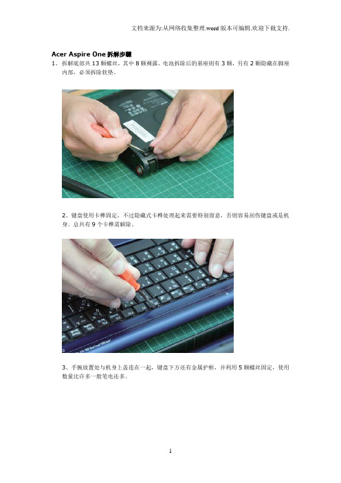
Acer Aspire One拆解步驟1、拆解底部共13颗螺丝,其中8颗裸露、电池拆除后的基座则有3颗,另有2颗隐藏在脚座内部,必须拆除软垫。
2、键盘使用卡榫固定,不过隐藏式卡榫处理起来需要特别留意,否则容易刮伤键盘或是机身。
总共有9个卡榫需解除。
3、手腕放置处与机身上盖连在一起,键盘下方还有金属护框,并利用5颗螺丝固定,使用数量比许多一般笔电还多。
4、机身上盖除了螺丝,在边缘也有卡榫,显示Aspire One非常重视机体的稳固性,松开螺丝后将卡榫扳开才能将上盖分离。
5、拆解到此步骤,主板已经裸露,可开始将组件移除,首先拆解无线网卡,这也是拆开上盖后唯一能移除更换的零件。
6、主板实际上分为两块,首先拆除位于侧边、负责I/O端口扩充之用的1块。
7、主要的主板拆解还必须移除周边连接的扁平电缆,图为与机身连接的讯号线。
8、此处则为音效连接线,Acer的设计颇为细心,此处有提供施力用的丝带,减少拉坏扁平电缆的可能性。
9、主板终于可以脱离机身,不过可以发现Aspire One相当特殊的一项设计,硬盘机的固定设计居然是与主板连接在一起。
10、拆除硬盘固定护框与主板的链接螺丝,将硬盘机卸下,整体拆解才算完成。
下面看看拆机用到的一些工具(老实说,One的模具做工非常地精致地~~)502胶用来把拆掉的橡胶脚垫粘回去;螺丝刀要用十字花的(大小两种规格,最好带有磁性);小平头螺丝刀和那张欧罗巴的VIP卡用来撬东西用的;至于镊子,没啥用,拍照时用来充数的,哈哈。
对了,再准备几个一次性纸杯或者盘子什么的,用来放拆下来的螺丝们~~*OK,开始拆屁屁上的螺丝们啦!!三种形状标注的螺丝长短是不一样滴~~胶垫下面的两个螺丝最长,胶垫可以用VIP卡的角撬下来滴~~三角形标注的螺丝最短,但是这三个螺丝最难拿下来,要紧紧地用螺丝刀顶紧来拧,否则容易把丝扣损伤的。
偶就把一颗螺丝拧坏了,后来用工具图中那种特大号的大螺丝刀才拧下来,惊出一身冷汗!!*接着就该拆键盘了~~画圈圈的地方会有一些卡扣,用VIP卡角轻轻地抵下去就能拆下键盘。
ACER Aspire One 拆机加内存全过程(中关村科技)(附图)

ACER Aspire One 拆机加内存全过程(附图)ACER Aspire One 拆机加内存全过程
首先拆机的第一步准备十字0号螺丝刀和两张电话卡
键盘上有三个卡槽
侧边有一个空的槽把卡插在这里
如图
同时上边上边配合
顺利拆下之后
小心迎面打开连接卡槽
卸下螺丝
0号螺丝刀
然后拆电脑底部的螺丝有两颗是隐藏在坐垫底下还原时用双面胶
然后是电池部位的螺丝
用卡沿着边缘轻轻划开
如图
这个触摸板的连接卡槽别忘了
卸下面板
面板背面
卸下的键盘和电池
机器内部
螺丝的位置
螺丝的位置
螺丝的位置
螺丝的位置
轻轻拔下
你可以拔掉声卡的线
小心拔掉显示器的线底部有双面胶
小心
小心拿掉整个主板
小心喇叭的螺丝
对称部位还有一个
轻松拿掉
如图
主板背面,这步加内存
atom1.6 cpu
集成到主办上的512m内存
全部
这个是喇叭的连接线觉得麻烦也可以卸下。
宏基(acer)Aspire 4930G拆机教程

宏基(acer)Aspire 4930G拆机教程我的电脑是宏基Aspire4930G系列的(具体型号是731G16Mn),到现在刚好用了一年,平时在学校用的时候都在下面放一个散热架,但是寒假回家之后发现不用散热架的电脑温度过高,鲁大师经常对CPU温度报警。
我只能用一会歇一会,就连游戏都不敢玩,今天下午跟朋友玩了会游戏电脑居然死机了,对于这个现象我有点忍无可忍了。
由于电脑已经过了保修期,去客服那清理灰尘已经不是免费的了,我于是就决定自己动手,上百度搜索了一下我这个型号电脑的拆机教程,上面只是给出了一些泛泛的指导,当时我还以为拆机不是很困难,就找了几个不同型号的螺丝刀开始了我的拆机尝试,但是不做不知道,一做下一跳,在拆机过程中出现的问题远比网上说得多。
有N个螺丝和N+1条排线,一不小心可能就能把电脑拆坏,还好在我小心翼翼的努力下经过了一个多小时的工作终于把电脑的所有零件都拆下来清理了一下,重新装起来之后电脑还能正常工作,说明我的这次很有风险的尝试还算成功。
下面就把我的拆机过程详细的介绍给大家。
1.这是拆机前的样子2.按照图中画圆圈标定的螺丝位置先拆下背面的所有螺丝和保护盖(注:背面一共6个较小的螺丝,13个较大的螺丝其中有几个是固定保护盖的,在这里没有画出)3.拆下硬盘和无线网卡(无线网卡上有两个固定的螺丝必须先拆下,并且一黑一白两根导线要轻轻地从上面摘下,这两根导线连接着屏幕)4.拆下键盘先找到键盘上两个卡扣,用小螺丝刀将卡扣压进卡槽,轻轻向上搬动最上排的按键就可以轻松地把键盘拆下但是不要太用力,因为键盘下边连着排线,如果用力太大会将排线扯坏,从此步之后会经常遇到排线拆卸。
拆卸排线时只要两手分别用一个螺丝刀同时轻轻地将压住排线的卡扣向外搬动,然后将排线向外轻轻抽出就可以了,以后对于的处理方法也一样。
接下来将标记处的排线都拆下5.拆下靠近屏幕的开机键以及多媒体键区域由于背面的螺丝已经全部拆除,所以现在这个区域已经没有螺丝固定所以只要沿着这个区域的外延用小螺丝刀轻轻撬动就可以轻松的将其拆下,不过值得注意的是这个键区仍有一个排线,应用上面介绍的方法就可以将其拆下6。
宏基上网本拆机图解
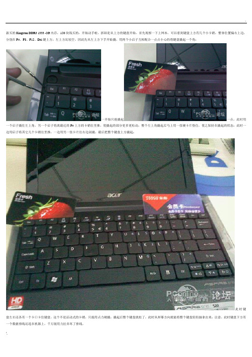
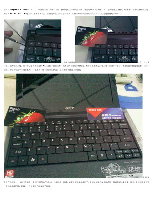
新买的Kingston DDR3 1333 -2G内存,150块钱买的:开始动手啦,拆卸是从上方的键盘开始。
首先观察一下上网本,可以看到键盘上方有几个小卡销,整体位置偏右上边,分别在F4、F8、F12、Del键上方;左上方比较空,因此先从左上方下手开始撬。
用两个小启子互相配合一点点小心的将键盘撬起一个角:一开始只能撬起一点,此时用一个启子撬住左上角,另一个启子将离最近的F4上方的卡销往里推,使撬起的部分更多更松动;整个左上角撬起后马上用一张硬卡片垫住,使之保持在撬起的状态:此时一边用启子将其它几个卡销往里推,一边用另一张卡片往右边刮撬,最后把整个键盘上方撬起;此时键盘左右还各有一个卡口卡住键盘,这个不是活动式的卡销,只能用点力硬撬,撬起后整个键盘就松了,此时从屏幕方向就能将整个键盘轻轻抽拿出来;注意,此时键盘下方有一个数据排线还连在机器上,千万别用力拉弄坏了排线。
这是键盘底下连着机器的排线:下一步是拆下排线(如果怕麻烦可以不拆这个排线,不过后面的步骤就需要时时非常小心以避免损坏排线)。
注意图片中卡住排线的那个插座,上方黑色部分是焊在机器的电路板上的,下面白色部分是连在上面的卡子,可活动的,往上推到顶可以把排线紧紧压在插座上,这是安装好的状态;用启子轻轻的将卡子左右的两个卡脚往下拨(见红箭头),这样白色的卡子就推下来了,排线就松了,轻轻的就拔了出来。
拔去排线后的插座,注意,白色的卡子已经推到了下方。
拆去键盘后的下面景象。
接下来用十字螺丝刀拆下四个标注“1”的螺丝;然后用螺丝刀对准标注为“2”的孔伸进去朝下推,稍微用点力,可以把上网本的底部整体盖板推下来;注意要先把整个上网本抱住左右两侧端起来,不要压住底盖,否则推不动的。
侧面看去,看到没,底盖一个角已经被推开了,顺势把整个底盖掰下来吧。
拆开底盖后的AspireOne522,内存条、硬盘一目了然;呵呵,此时想干啥就干啥吧。
换好内存后,机器拆下来的东西原样装回去就是,不再多叙述了;装键盘排线的时候要小心点,装好后别急着扣紧键盘,可先试试看好不好。
宏基上网本拆机图解
新买的Kingston DDR3 1333 -2G内存,150块钱买的:开始动手啦,拆卸是从上方的键盘开始。
首先观察一下上网本,可以看到键盘上方有几个小卡销,整体位置偏右上边,分别在F4、F8、F12、Del键上方;左上方比较空,因此先从左上方下手开始撬。
用两个小启子互相配合一点点小心的将键盘撬起一个角:一开始只能撬起一点,此时用一个启子撬住左上角,另一个启子将离最近的F4上方的卡销往里推,使撬起的部分更多更松动;整个左上角撬起后马上用一张硬卡片垫住,使之保持在撬起的状态:此时一边用启子将其它几个卡销往里推,一边用另一张卡片往右边刮撬,最后把整个键盘上方撬起;此时键盘左右还各有一个卡口卡住键盘,这个不是活动式的卡销,只能用点力硬撬,撬起后整个键盘就松了,此时从屏幕方向就能将整个键盘轻轻抽拿出来;注意,此时键盘下方有一个数据排线还连在机器上,千万别用力拉弄坏了排线。
这是键盘底下连着机器的排线:下一步是拆下排线(如果怕麻烦可以不拆这个排线,不过后面的步骤就需要时时非常小心以避免损坏排线)。
注意图片中卡住排线的那个插座,上方黑色部分是焊在机器的电路板上的,下面白色部分是连在上面的卡子,可活动的,往上推到顶可以把排线紧紧压在插座上,这是安装好的状态;用启子轻轻的将卡子左右的两个卡脚往下拨(见红箭头),这样白色的卡子就推下来了,排线就松了,轻轻的就拔了出来。
拔去排线后的插座,注意,白色的卡子已经推到了下方。
拆去键盘后的下面景象。
接下来用十字螺丝刀拆下四个标注“1”的螺丝;然后用螺丝刀对准标注为“2”的孔伸进去朝下推,稍微用点力,可以把上网本的底部整体盖板推下来;注意要先把整个上网本抱住左右两侧端起来,不要压住底盖,否则推不动的。
侧面看去,看到没,底盖一个角已经被推开了,顺势把整个底盖掰下来吧。
拆开底盖后的AspireOne522,内存条、硬盘一目了然;呵呵,此时想干啥就干啥吧。
换好内存后,机器拆下来的东西原样装回去就是,不再多叙述了;装键盘排线的时候要小心点,装好后别急着扣紧键盘,可先试试看好不好。
宏基(acer)Aspire4930G拆机教程

宏基(acer)Aspire4930G拆机教程宏基(acer)Aspire 4930G拆机教程电脑是宏基Aspire4930G系列的(具体型号是731G16Mn),鲁大师经常对CPU温度报警。
1.拆机前的样子2.按照图中画圆圈标定的螺丝位置先拆下背面的所有螺丝和保护盖(注:背面一共6个较小的螺丝,13个较大的螺丝其中有几个是固定保护盖的,在这里没有画出)3.拆下硬盘和无线网卡(无线网卡上有两个固定的螺丝必须先拆下,并且一黑一白两根导线要轻轻地从上面摘下,这两根导线连接着屏幕)4.拆下键盘先找到键盘上两个卡扣,用小螺丝刀将卡扣压进卡槽,轻轻向上搬动最上排的按键就可以轻松地把键盘拆下但是不要太用力,因为键盘下边连着排线,如果用力太大会将排线扯坏,从此步之后会经常遇到排线拆卸。
拆卸排线时只要两手分别用一个螺丝刀同时轻轻地将压住排线的卡扣向外搬动,然后将排线向外轻轻抽出就可以了,以后对于的处理方法也一样。
接下来将标记处的排线都拆下5.拆下靠近屏幕的开机键以及多媒体键区域由于背面的螺丝已经全部拆除,所以现在这个区域已经没有螺丝固定所以只要沿着这个区域的外延用小螺丝刀轻轻撬动就可以轻松的将其拆下,不过值得注意的是这个键区仍有一个排线,应用上面介绍的方法就可以将其拆下6。
卸下面板上的螺丝并拆掉屏幕排线。
(此处有8个较小螺丝2个较大螺丝图中指标出三个较小的螺丝,其余的螺丝都在刚刚拆下的多媒体键面板下方,其中有两个较大螺丝和两个较小螺丝是固定屏幕的,将这四个螺丝拆下之后要小心扶住屏幕防止屏幕摔坏)屏幕排线(黄色圆圈)7.卸下屏幕同时拔出无线网卡连在屏幕上的两根导线(无线网卡连接到屏幕有两根天线,也就是前面提到的那一黑一白两根导线,由于这样根导线会妨碍以后的操作,必须现在抽出,这两根导线从机器的下底壳穿到上面板线路比较复杂所以要记清楚走线的方式。
背面的线路8,拆下正面的面板,这步需要小心进行,面板下面有很多线路和接口,用小螺丝刀撬动边缘的缝隙,当所有的暗扣都被撬开后,两手抬起面板,注意要垂直地抬,不要让某些固定不牢的零件移位。
神州笔记本拆机图解
神州笔记本拆机图解神州笔记本拆机图解国内笔记本电脑市场中,有这样一个特立独行的品牌:对消费者而言,它总是以极具诱惑力的低价冲击着众人的眼球;而对其他品牌的'厂商而言,由低价所产生的所谓极其优异的性价比被认为是整体销售市场中极其不协调的音符,这就是神舟系列笔记本电脑。
下面就由店铺跟大家分享神州笔记本拆卸全过程,欢迎大家来阅读学习~神州笔记本拆机图解第一步:准备工作将工具(细十字螺丝刀、一字螺丝刀、镊子、刀片、软布)及待拆笔记本准备好。
2第二步:拆电池将笔记本背面朝上,把电池的固定锁扣打开,取出电池。
3第三步:拆背面护板将笔记本背面两片护板的固定螺丝拆开,取下护板。
第四步:拆硬盘拔开硬盘排线,取出硬盘。
第五步:拆网卡从数据插槽中轻轻拔出网卡,轻轻撬开电源线金属卡子,网卡取出。
第六步:拆扣条将笔记本正面朝上,液晶屏打开,将键盘上部扣条轻轻撬开上翻,然后,将与主板连接的排线打开,取出扣条。
第七步:拆键盘将键盘轻轻撬开上翻(千万要注意别扯断下面的排线),拆开排线,取下键盘。
第八步:拆液晶屏将液晶屏与主板的两根连接线拆开,包括电源线、数据线,拧开显示屏固定螺丝,取下显示屏。
第九步:拆触摸板轻轻拆开触摸板与主板的连接排线,取下触摸板主壳体。
第十步:拆光驱等拆开固定螺丝,将背面的光驱、散热片及风扇拆除。
第十一步:拆主板将图中的排线及旁边线路的插口拔开,然后,拆主板时注意下面的连接线,拆下主板及附件。
第十二步:拆内存轻轻向两侧推内存条固定金属卡子,内存条会向上弹起,然后,拔出内存条。
第十三步:拆CPU松开CPU的金属卡子,拔出CPU。
至此,笔记本电脑拆解完毕。
【最新精选】宏碁笔记本电脑内存条拆机扩展教程e1-471g
【最新精选】宏碁笔记本电脑内存条拆机扩展教程 e1-471g宏碁笔记本电脑内存条拆机扩展教程以下以E1-471G系列为例增加内存条E1-471G1.关闭笔记本计算机。
2. 如果不确定笔记本计算机是处于关机状态还是处于休眠状态,请先在Windows 中打开笔记本计算机,然后再通过 Windows 操作系统将其关闭。
3. 断开所有与笔记本计算机相连的外接设备。
4. 断开笔记本计算机和外部电源的连接。
翻转笔记本计算机,令其底面朝上5. 取出电池组。
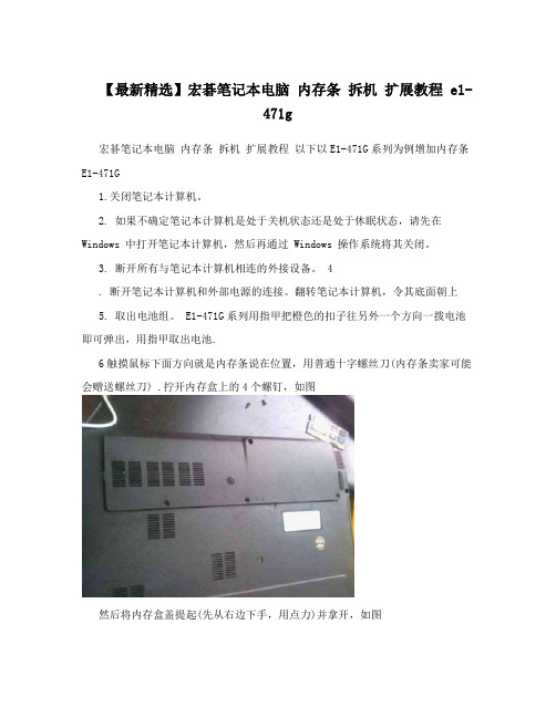
E1-471G系列用指甲把橙色的扣子往另外一个方向一拨电池即可弹出,用指甲取出电池.6触摸鼠标下面方向就是内存条说在位置,用普通十字螺丝刀(内存条卖家可能会赠送螺丝刀) .拧开内存盒上的4个螺钉,如图然后将内存盒盖提起(先从右边下手,用点力)并拿开,如图取出或插入内存模块。
要取出内存模块,请执行以下操作: a. 拉开内存模块两侧的固定夹。
(内存模块向上翘起。
) b. 握住模块的边缘,然后轻轻地将其从内存插槽中延抬起方向拔出图 2 要插入内存模块,请执行以下操作: a. 将内存模块缺口(槽口)边缘对准内存插槽的凸起处。
如果只需将一个内存模块插入空的内存盒中,请将该模块插入底部的插槽中。
(下图显示的是正要向内存盒的第二个插槽中装入的内存模块,该内存盒中已装有一个内存模块。
) b. 当内存模块与内存盒表面成 45 度角时,将此模块压入内存模块插槽直至就位。
c. 向下推内存模块,直到固定夹自动卡入到位。
要关闭内存盒,请将内存盒盖上的卡舌对准笔记本计算机上的盖板插槽,然后在内存盒上滑动盖板直至就位,拧紧内存盒的4个螺钉,如图 4 圈 2 所示。
重新装上电池组,重新将笔记本计算机连接到外接电源,然后重新启动笔记本计算机实图~----------------------------------------------------目前市场上还有不少低端的笔记本电脑的内存配置只有128MB,这样在运行主流WindowsXP操作系统的时候感觉就像拉牛上树,而主流的256MB内存也不见得能让XP运行如飞,512MB已经成为很多用户追求并可以实现的标准。
笔记本拆解全程解读
笔记本拆解全程解读最近天气越来越热,笔记本的温度也越来越高,尤其是运行大型程序的时候,趁今天有空,把笔记本拆开清理了一下,顿时觉得清爽了不少。
顺便写个拆解笔记,给想要清理笔记本的朋友一个参考。
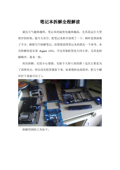
本次拆解的是宏碁Aspire 1551,不过其他机型也大同小异,尤其是拆解顺序,基本一致。
初次拆解,比较小心谨慎,先贴个大卸八块的图(这次主要是为了清理灰尘,所以没有把屏幕拆下来。
如果想拆也很简单,把几个螺丝拧下来就可以了):拆解用到的工具如下:从左到右依次是:洗耳球、万用螺丝刀(带磁性最好)、刷子、小螺丝刀、镊子。
前期准备:洗洗手、晾干、找个金属物体(如铁栏杆、楼梯扶手……)双手摸一摸(除去静电)。
拆解步骤:1、断开笔记本电源,卸下电池。
2、笔记本背面朝上,拆下中间的小盖子。
拆解后如图:此时可以看到笔记本的内存条、硬盘。
现在的笔记本一般有两个内存插槽,想扩展内存的话自己买个与原内存条同样规格的内存条,插在另外一个插槽,按下卡住即可,一般不会有问题,不用找个奸商花几十块钱装一下。
内存条特写3、拆下内存条和硬盘。
内存条:两边有两个卡扣,朝两边掰开,内存条会自动弹起,拔出即可。
安装的时候,先将内存条完全插入卡槽,再按下去让两个卡扣卡住即可。
硬盘:硬盘周围可能会有固定螺丝,先把螺丝拆下,然后硬盘一端会有专门拉出硬盘的塑料片,顺着硬盘方向小心拉出即可。
因为另外一端是金手指,所以拉出的时候角度越小越好。
内存条和硬盘要放好,这两个东西直接影响到电脑的运行。
拆解后:4、把后盖上所有的螺丝拆下,一定要是所有!!!还有网卡及其连接线。
(应该是无线网卡,不是很确定。
连接下直接连着屏幕,所以不用拆下,只要从线槽中拔出来即可)螺丝如图中黄色标记:5、翻转笔记本,把笔记本正面朝上,露出键盘。
6、拆下键盘,把键盘接口从插槽中拔出。
键盘周围会有很多卡扣,一般从上端(靠近屏幕一端)将卡扣一一推回,键盘即可弹起,然后慢慢拔出。
键盘容易弯曲,所以虽然卡扣很多,也不难拆下。
惠普Paviliong4系列笔记本拆解(教程)
惠普Pavilion g4系列笔记本拆解——以1017TX为例(图文教程)写在最前面:1.为什么要拆解?机器用久了,里面会进入很多灰尘,造成机器散热差、声音大,有时候也会拖慢机器的运行速度。
拆解之后,可以清理里面的垃圾。
2.里面的零件很脆弱,请务必小心。
3.拆解过程中用不到任何蛮力,如若拆解需要强力,说明你得换个思路把它拆开。
最后说一下,只有胆大心细才能完整的拆解。
4.拆解过程中胆大心细是非常重要的。
5.对自己没信心的最好别弄,零件很脆弱,弄坏了就不免要破费了。
但照着我的做法,胆大心细就没问题了。
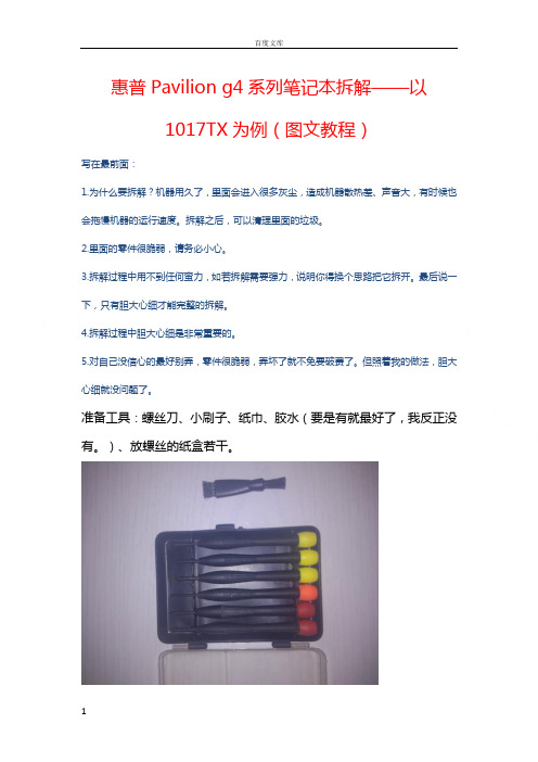
准备工具:螺丝刀、小刷子、纸巾、胶水(要是有就最好了,我反正没有。
)、放螺丝的纸盒若干。
步骤:1.收拾好桌子,腾出一个专用区域来,把工具摆放好,工具区与工作区分开。
(这是个细节问题,为了方便操作。
愿不愿意无所谓。
)2.把电池拆了,扔到一边去。
3.先拆卸以下螺丝;然后拆卸电池槽内的三个螺丝。
(螺丝放好了,找不见别怪我。
)4.然后再把后面的这个遮罩拆下来。
拆的时候注意了,先从电池槽那里入手,然后从两个螺丝的地方用小号螺丝刀微微撬一下就好了,别太用力,我感觉这东西很脆,慢慢地取下来。
5.先把硬盘拆下来;完了拆卸以下的螺丝;然后把WiFi模块的螺丝卸下来,别动模块,拆不下来。
6. 拆下硬盘下面的两个螺丝;然后在右侧把光驱拉出来(我知道比较难,用点技巧)。
7.把笔记本反过来,看看键盘的大概位置。
然后再看看光驱的地方,发现有个大一点的洞,多顶一顶就把键盘顶出来了。
看清楚地方,别弄错了。
然后翻过来把键盘拆了。
键盘和下面有线连着,要小心了(我没小心也拆下来了)。
再说一次,小心下面的线。
8. 然后把下面三个口松开。
9.然后沿着缝隙,把正面的盖子拿下来。
10.拔线扣,松螺丝。
11.小心点,把主板拿下来。
然后拆风扇。
12.风扇有两个螺丝,三个金属扣,注意了。
其中一个螺丝可见,另一个不可见。
13.我没胶水,所以啊,我不能让风扇和主板分离,不然风扇怎么装啊。
笔记本屏幕拆机教程-acer

工欲善其事必先利其器。
螺丝刀绝对是电脑玩家必备,相信各位手中也不会少。
刀头各种各样,其实很多很少用到,但是万一需要的时候又真是没有不行。
比如任天堂专用的Y字形等等。
对于拆笔记本来说,其实必备的也就是几种尺寸的十字和一个一字(主要做撬棍用,选薄的,在保证强度前提下越薄越方便。
我用的专门的弯头)镊子在对付某些细小部件时候有很好的效果,但不是必须导热硅脂,用于CPU和散热器之间的导热。
如果不拆开CPU散热器则不需要。
我用的是北极银5,12克装。
Amazon价格20美金。
另外除了所有的工具之外,还需要一个至少一平方米的操作空间,因为会有很多零件需要摆放,千万不要乱丢,否则你会后悔的。
===============================正式开工,我这里就以我自己的ACER 4736z为例子进行。
首先拔出所有的连接线缆并退出读卡器内的卡片。
然后将笔记本翻到D面。
拆除电池。
在地毯房里操作,容易有静电,安全考虑最好先去洗个手,水流会带走电荷。
冬天尤其必要。
卸掉所有可以拆卸的盖板。
部分厂商可能会在这些上面贴上易碎贴,作为保修凭证。
如果不想失去保修的话,电吹风伺候吧。
手上一定要小心。
我自己是懒得做的,无所谓。
自觉RP还可以,从来不保修。
一般情况下,所有盖板的螺丝都是固定在盖板上的,避免丢失。
如果没有固定的,需要妥善保管。
最好和盖板放在一起。
无线网卡上,一般会连接有天线,有条件记得拍照记下接线位置,避免接错。
内存部分都是有下图圈中这样的卡扣卡住。
按照箭头方向推开卡扣就行了。
推开之后内存会自动弹起,顺势拔出即可。
硬盘部分则不尽相同,有各种的锁定方式,有的还需要再拆卸螺丝,不过大多提供塑料弹片便于拖拽。
按照指引拆卸吧。
对于我的笔记本,往箭头方向拖拽,使框中金手指部分脱离即可。
无线网卡,内存,硬盘拆下后妥善放置。
回来看拆下部件之后的D面,下一步的工作是拆除该面所有螺丝。
找来一张白纸,对应D面螺丝孔位,在纸上相应位置画下小圈,不需要十分精确。
宏碁笔记本内存条怎么拆
宏碁笔记本内存条怎么拆
想知道怎么拆笔记本的内存条吗?下面是店铺带来宏碁笔记本内存条怎么拆的内容,欢迎阅读!
宏碁笔记本内存条怎么拆:
在安装之前,将笔记本电脑的电源完全切断,并将电池取出来。
将笔记本电脑的底部朝上,确定内存扩展插槽的位置(说明书上可以查到),目前大部分笔记本电脑的内存扩展插槽都设置在笔记本电脑的底部。
但也有少数机型的内存插槽设置在键盘下的位置。
用合适的螺丝刀拧开内存扩展插槽的固定螺丝,打开封盖。
将内存边缘连接器的槽口与连接器卡槽中的卡舌对齐,将内存45度角稳固的滑入插槽,并向下转动内存直至其卡入其位。
如果未感到其卡入,则卸下内存并重新安装。
内存安装完成后,上螺钉复原内存封盖,装好电池。
开机进入系统,打开系统属性界面。
如果系统不能正确的识别新的内存容量,则说明内存没有装好,按照上面的步骤重新安装内存,直至内存装好。
4750g宏基 超明了详细拆机步骤

今年高考结束,疯玩了2个多月,快开学的时候软磨硬泡父母终于给买了一台宏碁4750G。
前天发了生活费,路过文具店突然看到有卖螺丝刀套装的,一时冲动想把笔记本拆开看看,就买回来了。
工具盒OK,开拆!自然要从D面入手了。
将十字螺丝刀插刀电池锁扣中向箭头所指方向轻拨,电池就取下来了。
然后将12颗螺丝全部卸下。
其中5号螺丝卸下后就可以将光驱抽出,3、4号螺丝卸下后才能取下键盘。
D面卸下7、8、9号螺丝后,就可以把小背盖打开,可以看到硬盘、无线网卡和内存。
将A螺丝卸下后向左轻推可以将硬盘取下。
B、C固定的是硬盘保护盒,可以不卸。
D、E是无线网卡天线,轻轻把它拔下来以便稍后取下主板。
还要把F、G、H三颗螺丝卸下来。
硬盘、无线网卡、内存下一步取下C面,先取键盘。
其中a~e是伸缩卡扣,用平口螺丝刀往里一按就开了。
f、g是固定卡扣,h~l是几个小槽。
伸缩卡扣全部打开后,将平口螺丝刀插入箭头位置轻推,键盘基本脱离原位了,然后把螺丝刀插入键盘下方向上顶,就可以将键盘取出,但不要急着拿走!下面还有连线与主板相连呢!键盘取连线时,将红框中的黑色压片向上一掰即可。
注意压片与插槽是一体的,千万别用蛮力把它扯下来,不然就废了!一定要小心~键盘连线键盘拆下后还有两处数据线需要取下,取法跟键盘数据线是相同的。
取完后就可以将C面取下了C面C面取下后主板背面暴露无遗~~主要部件如下:1、电源接口;2、屏幕连线(请小心地拔下);3、有线网卡;4、读卡器;5、BIOS电池;6、USB及音频接口(连线需取下);7、USB3.0接口;8、显存(正反8个共2G)主板背面拔下屏幕连线,取下USB+音频连线,再卸下背面白色圈中的两颗螺丝。
如果无线网卡的两根天线已经取下,那么就可以比较轻松地取下主板了。
图中预留的SIM卡焊口据说可以焊上SIM卡卡槽然后就可以使用3G上网了。
主板正面卸上图黑圈中的螺丝,其中显卡旁边的可以卸下,CPU周围的三颗螺丝是弹簧螺丝,拧松即可。
ACER 宏碁 Aspire 5021完全拆解

ACER 宏碁 Aspire 5021完全拆解第一步就是把电源键的那块塑料挡板剥开,然后就可以看见显示屏的,天线的,MIC的,屏幕开合感应器的插头拔出,第二步,把键盘拿下来注意:1`还有触控板的排线要拔;2`把键盘拿下来之后右手边还有一个螺丝,固定在金属片上的,一定要拿下,这个固定螺丝很容易漏掉;3`事先把无线网卡的天线拔出,要把天线直接从面板上抽出来;螺丝扭开,就可以把屏拿出来了面板要从屏这边开始拉逐渐拉起来,切记不要用蛮力面板的背面,可见大量帮助散热的材料主板上有两颗螺丝,一根音箱线,还有散热风扇,都要一一拆下才能拿起主板拆主板的时候注意是从音箱这边拿起,途中要注意左手边的USB和1394接口,要稍微把底座的塑料外扯一点才能顺利拿起拿起来后把整个主板往音箱这边拉一下,剩个主板即可取出主板底面图2:去掉散热器的CPU,离内存插槽非常近,设计非常合理!图3:X600的显卡,原来是直接做在主板上的,5555我哭,换显卡的愿望破灭了,本来还想换显卡的;图4:这个应该是猫??还是网卡呢?看看CPU 的散热器,CPU,和底下的脚该CPU 插槽和台机的有一点区别,没有台机主板上的扳手,是用螺丝来固定的,其实原理和台机的零插力底座的原理是一样的看来是很有拆机的必要的下面来看看我的工具:一把瑞士军刀.可能有XD 会问,够不够.告诉大家,足矣.旁边还有一把松下剃须刀送的毛刷(有两头的,一头是硬的,一头是软的,便于清扫)清扫完毕,20分钟后装好机器,开机,....我倒,只看见电源亮了,风扇转了一下,光驱动了一下,就再没有反映了,当时就急出一身冷汗.....仔细检查之下还是没有发现问题,开始怀疑是硬盘的没插好,从新插过,故障依旧,晕了,难道5021就让我这样给弄费了?!再试内存,好家伙,还真的是这里的问题记得原来加内存的时候也是这故障,好,问题解决,一切完成!开机,一切正常1`经过这次拆机,机器内部焕然一新,特别是散热器和风扇的清扫,使风扇的启动次数明显减少噪音有所降低2`发现了为蓝牙模块预留的接口和空间,以后可以自己加了3`非常失望的是,显卡是直接做在了主板上,没法升级了的本来有过多次拆原来的IBM T23的经验,使得这次的拆机比较顺利,基本没有对机器造成什么损伤请大家珍惜自己的电脑,不要随便拆啊~~~~失保修别找我~~。
JM41_EPEAT
Aspire 4810 Series Disassembly InstructionMachine Disassembly and ReplacementThis chapter contains step-by-step procedures on how to disassemble the notebook computer formaintenance and troubleshooting.Disassembly RequirementsTo disassemble the computer, you need the following tools:•Wrist grounding strap and conductive mat for preventing electrostatic discharge•Flat screwdriver•Philips screwdriver•Hex screwdriver•Plastic flat screwdriver•Plastic tweezersNOTE: The screws for the different components vary in size. During the disassembly process, group the screws with the corresponding components to avoid mismatch when putting back the components.23General InformationPre-disassembly InstructionsBefore proceeding with the disassembly procedure, make sure that you do the following:1.Turn off the power to the system and all peripherals.2.Unplug the AC adapter and all power and signal cables from the system.3.Place the system on a flat, stable surface.4.Remove any dummy card that might still be inside the card slot.Disassembly ProcessThe disassembly process is divided into the following stages:•External module disassembly •Main unit disassembly •LCD module disassemblyThe flowcharts provided in the succeeding disassembly sections illustrate the entire disassembly sequence. Observe the order of the sequence to avoid damage to any of the hardware components. For example, if you want to remove the main board, you must first remove the keyboard, then disassemble the inside assembly frame in that order. Main Screw ListItem ScrewColor Part No.A M2 x L4Black 86.00E13.524B M2 x L3Silver 86.9A522.3R0C M2.5 X L3.5Silver 86.9A563.3R5D M3 x L3Black 86.00E90.743E M2.5 x L6Black 86.00E12.536F M2.5 x L11Black 86.1A353.110G M2 x L2.5Silver 86.9A562.2R5H M2.5 x L5Black 86.00F87.735I M2 x L6Black 86.00K64.524JM2 x L3Black86.00K60.630External Module Disassembly ProcessItem Screw ColorB M2 x L3SilverD M3 x L3BlackF M2.5 x L11Black451.Turn base unit over.2.Slide the battery lock/unlock latch to the unlock position.3.Slide and hold the battery release latch to the release position.4.Then slide out the battery from the battery bay.Note: Battery has been highlighted with the red rectangle as above image shows. Please detach the61.See “Removing the Battery Pack” on page 5.2.Remove the two screws (F) and five captive screws securing the lower cover.e a plastic screw driver to carefully pry open the lower cover.4.Remove the lower cover from the lower case.StepSize (Quantity)Color Torque1~2M2.5 x L11 (2)Black3.0 kgf-cm7Removing the Optical Drive Module1.See “Removing the Battery Pack” on page 5.2.See “Removing the Lower Cover” on page 6.3.Use a screw driver and carefully push out and slide out the optical drive module out of the bay.4.Remove the one screw (B) securing the locker bracket and remove the locker bracket from the optical disk drive module.Removing the DIMM1.See “Removing the Battery Pack” on page 5.2.See “Removing the Lower Cover” on page 6.StepSize (Quantity)Color Torque1M2 x L3 (1)Silver1.6 kgf-cm83.Push out the latches on both sides of the DIMM socket to release the DIMM and remove it from the socket.4.Do the same to the other socket if there is any DIMM present.Removing the Hard Disk Drive Module1.See “Removing the Battery Pack” on page 5.2.See “Removing the Lower Cover” on page 6.3.Using the plastic tab, lift up the the hard disk drive module and remove it from the bay.NOTE:To prevent damage to device, avoid pressing down on it or placing heavy objects on top of it.94.Remove the two screws (D) securing the hard disk to the bracket and remove the hard disk from the bracket.Removing the SSD Module1.See “Removing the Battery Pack” on page 5.2.See “Removing the Lower Cover” on page 6.3.Using the plastic tab, slide the SSD module away from the connector and lift to remove it from the system.Removing the RTC Battery1.See “Removing the Battery Pack” on page 5.2.See “Removing the Lower Cover” on page 6.StepSize (Quantity)Color Torque1~2M3 x L3 (2)Black3.0 kgf-cm3.Disconnect the RTC battery cable from the system board and lift to remove it.NOTE: Be careful when removing the RTC battery. It is glued to the system board.Note: Battery has been highlighted with the red rectangle as above image shows. Please detach the10Main Unit Disassembly ProcessItem Screw ColorA M2 x L4BlackE M2.5 x L6BlackH M2.5 x L5BlackI M2 x L6BlackRemoving the Keyboard1.See “Removing the Battery Pack” on page 5.2.Release the keyboard from the latches securing it.3.Carefully pry loose the keyboard.4.Place the keyboard below the LCD screen to gain access to the keyboard cable.5.Disconnect the keyboard cable from the main board to remove the keyboard.Removing the WLAN Board Module1.See “Removing the Battery Pack” on page 5.2.See “Removing the Keyboard” on page 12.3.Disconnect the antenna cables from the WLAN board.NOTE: There are 2 antenna cables connected to the WLAN board. The Black antenna cable is connected to connector 1and the White antenna cable is connected to connector 2.4.Remove the one screw (A) on the WLAN board to release the WLAN board.5.Detach the WLAN board from the WLAN socket.NOTE: When attaching the antenna back to the WLAN board, make sure the cable are arranged properly.Separating the Upper Case from the Lower Case1.See “Removing the Battery Pack” on page 5.2.See “Removing the Lower Cover” on page 6.3.See “Removing the Lower Cover” on page 6.4.See “Removing the Optical Drive Module” on page 7.5.See “Removing the DIMM” on page 7.6.See “Removing the Hard Disk Drive Module” on page 8.7.See “Removing the SSD Module” on page 9.8.See “Removing the RTC Battery” on page9.9.See “Removing the Keyboard” on page 12.10.See “Removing the WLAN Board Module” on page 13.StepSize (Quantity)Color Torque1M2 x L4 (1)Black1.6 kgf-cm11.Remove the twelve screws (I, E, H) from the bottom panel.12.Disconnect the touchpad cable from the TPAD1 connector on the main board.13.Disconnect the function key board cable from the MMB1 connector on the system board.StepSize (Quantity)Color Torque1~2M2.5 x L6 (2)Black 3.0 kgf-cm 3~4M2 x L4 (2)Black 3.0 kgf-cm 5~12M2.5 x L5 (8)Black3.0 kgf-cm14.Disconnect the power button cable from the BTB2 connector on the system board.15.Disconnect the speaker cable from the SPK1 connector on the system board.16.Gently separate the upper case from the lower case.Removing the Power Button Board1.See “Removing the Battery Pack” on page 5.2.See “Removing the Lower Cover” on page 6.3.See “Removing the Lower Cover” on page 6.4.See “Removing the Optical Drive Module” on page 7.5.See “Removing the DIMM” on page 7.6.See “Removing the Hard Disk Drive Module” on page 8.7.See “Removing the SSD Module” on page 9.8.See “Removing the RTC Battery” on page 9.9.See “Removing the Keyboard” on page 12.10.See “Removing the WLAN Board Module” on page 13.11.See “Separating the Upper Case from the Lower Case” on page 14.12.Release the power button board from that latches and remove from the upper case.Removing the Touchpad Module1.See “Removing the Battery Pack” on page 5.2.See “Removing the Lower Cover” on page 6.3.See “Removing the Lower Cover” on page 6.4.See “Removing the Optical Drive Module” on page 7.5.See “Removing the DIMM” on page 7.6.See “Removing the Hard Disk Drive Module” on page 8.7.See “Removing the SSD Module” on page 9.8.See “Removing the RTC Battery” on page 9.9.See “Removing the Keyboard” on page 12.10.See “Removing the WLAN Board Module” on page 13.11.See “Separating the Upper Case from the Lower Case” on page 14.12.Disconnect the touchpad cable from the touchpad board; then carefully pry loose and remove the touchpad boardWARNING:The touchpad board is glued to the upper case, only remove the touchpad board if it is defective.Circuit board > 10cm2 has been highlighted with the red rectangle as shown in the figureRemoving the Speaker Module1.See “Removing the Battery Pack” on page 5.2.See “Removing the Lower Cover” on page 6.3.See “Removing the Lower Cover” on page 6.4.See “Removing the Optical Drive Module” on page 7.5.See “Removing the DIMM” on page 7.6.See “Removing the Hard Disk Drive Module” on page 8.7.See “Removing the SSD Module” on page 9.8.See “Removing the RTC Battery” on page 9.9.See “Removing the Keyboard” on page 12.10.See “Removing the WLAN Board Module” on page 13.11.See “Separating the Upper Case from the Lower Case” on page 14.12.Remove the two screws (A) securing the left and right speaker modules, peel off the stickers securing thespeaker cables, and remove them from the upper case.Removing the LED Board1.See “Removing the Battery Pack” on page 5.2.See “Removing the Lower Cover” on page 6.3.See “Removing the Lower Cover” on page 6.4.See “Removing the Optical Drive Module” on page 7.5.See “Removing the DIMM” on page 7.6.See “Removing the Hard Disk Drive Module” on page 8.7.See “Removing the SSD Module” on page 9.8.See “Removing the RTC Battery” on page9.9.See “Removing the Keyboard” on page 12.10.See “Removing the WLAN Board Module” on page 13.11.See “Separating the Upper Case from the Lower Case” on page 14.12.Peel off the covering of the LED board.StepSize (Quantity)Color Torque1~2M2 x L4 (2)Black1.6 kgf-cm13.Carefully pry loose and remove the LED board from the upper case.WARNING:The LED board is glued to the upper case, only remove the LED board if it is defective. Removing the LCD Module1.See “Removing the Battery Pack” on page 5.2.See “Removing the Lower Cover” on page 6.3.See “Removing the Lower Cover” on page 6.4.See “Removing the Optical Drive Module” on page 7.5.See “Removing the DIMM” on page 7.6.See “Removing the Hard Disk Drive Module” on page 8.7.See “Removing the SSD Module” on page 9.8.See “Removing the RTC Battery” on page 9.9.See “Removing the Keyboard” on page 12.10.See “Removing the WLAN Board Module” on page 13.11.See “Separating the Upper Case from the Lower Case” on page 14.12.Release the wireless antenna cables from the latches.13.Disconnect the LCD cable.14.Pell off the LCD cable from the fan.15.Remove the two screws (E) from the left and right hinge of the LCD module.Step Size (Quantity)Color Torque 1~2M2.5 x L6 (2)Black 3.0 kgf-cm16.Carefully remove the LCD module from the base unit.NOTE: When connecting the cables back to the unit, please note that the cables should be routed well. Removing the System Board1.See “Removing the Battery Pack” on page 5.2.See “Removing the Lower Cover” on page 6.3.See “Removing the Lower Cover” on page 6.4.See “Removing the Optical Drive Module” on page 7.5.See “Removing the DIMM” on page 7.6.See “Removing the Hard Disk Drive Module” on page 8.7.See “Removing the SSD Module” on page 9.8.See “Removing the RTC Battery” on page 9.9.See “Removing the Keyboard” on page 12.10.See “Removing the WLAN Board Module” on page 13.11.See “Separating the Upper Case from the Lower Case” on page 14.12.See “Removing the LCD Module” on page 20.13.Disconnect the card reader board cable from the system board.14.Disconnect the top daughter board cable from the system board.15.Disconnect the bottom system board cable from the daughter board.16.Remove the one screw (A) securing the system board and the mini board..Step Size (Quantity)Color Torque 1M2 x L4 (1)Black 1.6 kgf-cm17.Carefully remove the main board.Removing the Thermal Module1.See “Removing the Battery Pack” on page 5.2.See “Removing the Lower Cover” on page 6.3.See “Removing the Lower Cover” on page 6.4.See “Removing the Optical Drive Module” on page 7.5.See “Removing the DIMM” on page 7.6.See “Removing the Hard Disk Drive Module” on page 8.7.See “Removing the SSD Module” on page 9.8.See “Removing the RTC Battery” on page 9.9.See “Removing the Keyboard” on page 12.10.See “Removing the WLAN Board Module” on page 13.11.See “Separating the Upper Case from the Lower Case” on page 14.12.See “Removing the System Board” on page 22.13.Disconnect the thermal module cable from the system board.14.Turn over the system board and loosen the four captive screws securing the thermal module.15.Carefully remove the heatsink module from the system.Removing the Mini Board Module1.See “Removing the Battery Pack” on page 5.2.See “Removing the Lower Cover” on page 6.3.See “Removing the Lower Cover” on page 6.4.See “Removing the Optical Drive Module” on page 7.5.See “Removing the DIMM” on page 7.6.See “Removing the Hard Disk Drive Module” on page 8.7.See “Removing the SSD Module” on page 9.8.See “Removing the RTC Battery” on page 9.9.See “Removing the Keyboard” on page 12.10.See “Removing the WLAN Board Module” on page 13.11.See “Separating the Upper Case from the Lower Case” on page 14.12.See “Removing the System Board” on page 22.13.Remove the one screw (A) securing the mini board to the system board.14.Detach the system board from the mini board.Circuit boards > 10cm 2 has been highlighted with the red rectangle as shown in the figureRemoving the Daughter Board Module1.See “Removing the Battery Pack” on page 5.2.See “Removing the Lower Cover” on page 6.3.See “Removing the Lower Cover” on page 6.4.See “Removing the Optical Drive Module” on page 7.5.See “Removing the DIMM” on page 7.6.See “Removing the Hard Disk Drive Module” on page 8.7.See “Removing the SSD Module” on page 9.8.See “Removing the RTC Battery” on page 9.9.See “Removing the Keyboard” on page 12.10.See “Removing the WLAN Board Module” on page 13.11.See “Separating the Upper Case from the Lower Case” on page 14.StepSize (Quantity)Color Torque 1M2 x L4 (1)Black 1.6 kgf-cm12.See “Removing the System Board” on page 22.13.Release the daughter board from the latch.14.Carefully lift the daughter board and remove it from the lower case.Circuit board > 10cm2 has been highlighted with the red rectangle as shown in the figureRemoving the Card Reader Board1.See “Removing the Battery Pack” on page 5.2.See “Removing the Lower Cover” on page 6.3.See “Removing the Lower Cover” on page 6.4.See “Removing the Optical Drive Module” on page 7.5.See “Removing the DIMM” on page 7.6.See “Removing the Hard Disk Drive Module” on page 8.7.See “Removing the SSD Module” on page 9.8.See “Removing the RTC Battery” on page 9.9.See “Removing the Keyboard” on page 12.10.See “Removing the WLAN Board Module” on page 13.11.See “Separating the Upper Case from the Lower Case” on page 14.12.See “Removing the System Board” on page 22.13.Remove the one screw (A) securing the card reader board to the lower case.14.Remove the card reader board from the lower case.Circuit board > 10cm 2 has been highlighted with the red rectangle as shown in the figureRemoving the Bluetooth Module1.See “Removing the Battery Pack” on page 5.2.See “Removing the Lower Cover” on page 6.3.See “Removing the Lower Cover” on page 6.4.See “Removing the Optical Drive Module” on page 7.5.See “Removing the DIMM” on page 7.6.See “Removing the Hard Disk Drive Module” on page 8.7.See “Removing the SSD Module” on page 9.8.See “Removing the RTC Battery” on page 9.9.See “Removing the Keyboard” on page 12.10.See “Removing the WLAN Board Module” on page 13.11.See “Separating the Upper Case from the Lower Case” on page 14.StepSize (Quantity)Color Torque 1M2 x L4 (1)Black 1.6 kgf-cm12.See “Removing the Card Reader Board” on page 27.13.Disconnect the Bluetooth module cable from the bottom of the card reader board.14.Carefully pry loose and remove the Bluetooth module from the card reader board.WARNING:The Bluetooth module is glued to the card reader board, only remove the Bluetooth module if it is defective.Removing the Touchpad Lock Board1.See “Removing the Battery Pack” on page 5.2.See “Removing the Lower Cover” on page 6.3.See “Removing the Lower Cover” on page 6.4.See “Removing the Optical Drive Module” on page 7.5.See “Removing the DIMM” on page 7.6.See “Removing the Hard Disk Drive Module” on page 8.7.See “Removing the SSD Module” on page 9.8.See “Removing the RTC Battery” on page 9.9.See “Removing the Keyboard” on page 12.10.See “Removing the WLAN Board Module” on page 13.11.See “Separating the Upper Case from the Lower Case” on page 14.12.Carefully pry loose and remove the touchpad lock board from the lower case.WARNING:The touchpad lock board is glued to the lower case, only remove the touchpad lock board if it is defective.LCD Module Disassembly ProcessItem Screw ColorC M2.5 X L3.5SilverG M2 x L2.5SilverJ M2 x L3BlackRemoving the LCD Bezel1.See “Removing the Battery Pack” on page 5.2.See “Removing the Lower Cover” on page 6.3.See “Removing the Lower Cover” on page 6.4.See “Removing the Optical Drive Module” on page 7.5.See “Removing the DIMM” on page 7.6.See “Removing the Hard Disk Drive Module” on page 8.7.See “Removing the SSD Module” on page 9.8.See “Removing the RTC Battery” on page 9.9.See “Removing the Keyboard” on page 12.10.See “Removing the WLAN Board Module” on page 13.11.See “Separating the Upper Case from the Lower Case” on page 14.12.See “Removing the LCD Module” on page 20.13.Remove the four rubber screw covers from the LCD bezel.14.Remove the four screws (C) on the LCD module as shown.Step Size (Quantity)Color Torque 1~4M2.5 x L3.5 (4)Silver 3.0 kgf-cm15. Carefully pry open the LCD bezel and and remove the bezel from the LCD panel.Removing the LCD Panel1.See “Removing the Battery Pack” on page 5.2.See “Removing the Lower Cover” on page 6.3.See “Removing the Lower Cover” on page 6.4.See “Removing the Optical Drive Module” on page 7.5.See “Removing the DIMM” on page 7.6.See “Removing the Hard Disk Drive Module” on page 8.7.See “Removing the SSD Module” on page 9.8.See “Removing the RTC Battery” on page 9.9.See “Removing the Keyboard” on page 12.10.See “Removing the WLAN Board Module” on page 13.11.See “Separating the Upper Case from the Lower Case” on page 14.12.See “Removing the LCD Module” on page 20.13.See “Removing the LCD Bezel” on page 32.14.See “Removing the LCD Panel Hinges” on page 35.15.Remove the four screws (G) securing the LCD panel to the back cover.16.Carefully lift up the LCD panel and turn it over to gain access to the LCD cable.17.Detach the acetic tape on the LCD cable.Step Size (Quantity)Color Torque 1~4M2 x L2.5 (4)Silver1.6 kgf-cm18.Detach the LCD cable from the LCD panel.19.Remove the LCD panel from the back cover.Removing the LCD Panel Hinges1.See “Removing the Battery Pack” on page 5.2.See “Removing the Lower Cover” on page 6.3.See “Removing the Lower Cover” on page 6.4.See “Removing the Optical Drive Module” on page 7.5.See “Removing the DIMM” on page 7.6.See “Removing the Hard Disk Drive Module” on page 8.7.See “Removing the SSD Module” on page 9.8.See “Removing the RTC Battery” on page 9.9.See “Removing the Keyboard” on page 12.10.See “Removing the WLAN Board Module” on page 13.11.See “Separating the Upper Case from the Lower Case” on page 14.12.See “Removing the LCD Module” on page 20.13.See “Removing the LCD Bezel” on page 32.14.Remove the hinge caps on both side of the hinges.15.Remove the four screws (J) securing the left and right hinges, and remove the hingesRemoving the Webcam1.See “Removing the Battery Pack” on page 5.2.See “Removing the Lower Cover” on page 6.3.See “Removing the Lower Cover” on page 6.4.See “Removing the Optical Drive Module” on page 7.5.See “Removing the DIMM” on page 7.6.See “Removing the Hard Disk Drive Module” on page 8.7.See “Removing the SSD Module” on page 9.8.See “Removing the RTC Battery” on page 9.9.See “Removing the Keyboard” on page 12.10.See “Removing the WLAN Board Module” on page 13.11.See “Separating the Upper Case from the Lower Case” on page 14.12.See “Removing the LCD Module” on page 20.13.See “Removing the LCD Bezel” on page 32.Step Size (Quantity)Color Torque 1~4M2.5 x L2.5 (4)Black1.6 kgf-cm14.Disconnect the cable from the webcam.15.Carefully pry loose the webcam.CAUTION: Only remove the webcam if it is defective as it is glued to the back cover. Removing the Microphone1.See “Removing the Battery Pack” on page 5.2.See “Removing the Lower Cover” on page 6.3.See “Removing the Lower Cover” on page 6.4.See “Removing the Optical Drive Module” on page 7.5.See “Removing the DIMM” on page 7.6.See “Removing the Hard Disk Drive Module” on page 8.7.See “Removing the SSD Module” on page 9.8.See “Removing the RTC Battery” on page 9.9.See “Removing the Keyboard” on page 12.10.See “Removing the WLAN Board Module” on page 13.11.See “Separating the Upper Case from the Lower Case” on page 14.12.See “Removing the LCD Module” on page 20.13.See “Removing the LCD Bezel” on page 32.14.Disconnect the cable from the microphone, then remove the microphone.。
宏基(acer)Aspire拆机

宏基(acer)Aspire拆机教程我的电脑是宏基Aspire系列的,到现在刚好用了一年,平时在学校用的时候都在下面放一个散热架,但是寒假回家之后发现不用散热架的电脑温度过高,鲁大师经常对CPU温度报警。
我只能用一会歇一会,就连游戏都不敢玩,今天下午跟朋友玩了会游戏电脑居然死机了,对于这个现象我有点忍无可忍了。
由于电脑已经过了保修期,去客服那清理灰尘已经不是免费的了,我于是就决定自己动手,上百度搜索了一下我这个型号电脑的拆机教程,上面只是给出了一些泛泛的指导,当时我还以为拆机不是很困难,就找了几个不同型号的螺丝刀开始了我的拆机尝试,但是不做不知道,一做下一跳,在拆机过程中出现的问题远比网上说得多。
有N个螺丝和N+1条排线,一不小心可能就能把电脑拆坏,还好在我小心翼翼的努力下经过了一个多小时的工作终于把电脑的所有零件都拆下来清理了一下,重新装起来之后电脑还能正常工作,说明我的这次很有风险的尝试还算成功。
下面就把我的拆机过程详细的介绍给大家。
1.这是拆机前的样子2.按照图中画圆圈标定的螺丝位置先拆下背面的所有螺丝和保护盖(注:背面一共6个较小的螺丝,13个较大的螺丝其中有几个是固定保护盖的,在这里没有画出)3.拆下硬盘和无线网卡(无线网卡上有两个固定的螺丝必须先拆下,并且一黑一白两根导线要轻轻地从上面摘下,这两根导线连接着屏幕)4.拆下键盘先找到键盘上两个卡扣,用小螺丝刀将卡扣压进卡槽,轻轻向上搬动最上排的按键就可以轻松地把键盘拆下但是不要太用力,因为键盘下边连着排线,如果用力太大会将排线扯坏,从此步之后会经常遇到排线拆卸。
拆卸排线时只要两手分别用一个螺丝刀同时轻轻地将压住排线的卡扣向外搬动,然后将排线向外轻轻抽出就可以了,以后对于的处理方法也一样。
接下来将标记处的排线都拆下5.拆下靠近屏幕的开机键以及多媒体键区域由于背面的螺丝已经全部拆除,所以现在这个区域已经没有螺丝固定所以只要沿着这个区域的外延用小螺丝刀轻轻撬动就可以轻松的将其拆下,不过值得注意的是这个键区仍有一个排线,应用上面介绍的方法就可以将其拆下6。
- 1、下载文档前请自行甄别文档内容的完整性,平台不提供额外的编辑、内容补充、找答案等附加服务。
- 2、"仅部分预览"的文档,不可在线预览部分如存在完整性等问题,可反馈申请退款(可完整预览的文档不适用该条件!)。
- 3、如文档侵犯您的权益,请联系客服反馈,我们会尽快为您处理(人工客服工作时间:9:00-18:30)。
cer Aspire timeline 渴望超越4810T (13步拆机+红外测温+电池续航+acer机型全集照) 首先感谢本友会给我这位acer爱好者一次直接
接触4810T的机会。
作为一名很普通的本友,热门的3810T和5810T,我自己估摸着不够资格,刚好4810T没人申请,也算运气不错吧。
既然机会到了,没有某些版主资深的玩系统的功力,也没有专业的照相设备,但我想,只要凭着爱好DIY的劲头,一定可以做一个尽量全面的评测,希望大家看了我的评测以后,能够知道,4810T是不是适合你,我的评测就算不辱使命了。
此贴共分为6个部分,本友可以选择自己关注的部分直接浏览。
第一部分timeline4810T到手感想及外观细节拍摄第二部分拆机仅需13步,timeline 4810T深度拆机+内部配件特写
第三部分轻薄能与性能兼具?timeline 4810T重要硬件全测试
第四部分红外上阵,timeline 4810T待机满载温度全测试
第五部分关于timeline4810T的总结以及遇到的一些问题,持续更新中
第六部分一个系列的经典,Aspire迎接新成员timeline+宝石模具大回顾
在做评测的同时,已经发现acer台湾官网更新了4810TG高配的信息。
截下了一张图,大家看看。
居然采用SU9400+ATI 4330的配置,不过貌似没有SU9400+X4500的配置。
3
篇外话
2007年国庆我拥有了第一台笔记本aspire 4720G,圆润的外观,白色的键盘,都让我由衷的喜爱它。
最重要的是,它让我明白了,笔记
本也可以DIY。
此机在这一年半中,已经更换过CPU、硬盘、显卡,加装了内置蓝牙适配器。
2008年10月,家里再添新机aspire 4730zg,此时模具已经改用了宝石二代模具,此本依然强悍,MXM接口等一应俱全,而宝石二代模具内部感觉仅仅是颜色变为了黑色,屏幕外壳试用了深蓝色的钢琴烤漆工艺。
我觉得acer那时候的屏幕转轴都不太稳,一直希望他能够改进。
2009年3月,身边最好的朋友,在我的强烈建议之下,购买了aspire 4735zg。
4735zg已经又在宝石二代的基础上进行了一次升级,变薄了,但是也失去了MXM接口。
最重要的是,转轴终于改了,非常稳定!当时我就感觉,acer难道准备不给我们DIYER机会了,都取消独立显卡插槽了,难道他预谋下个系列变得更薄?
2009年6月,timeline来了,当我收到timeline 4810T的时候,第一个在脑海中出现的词语就是惊叹!虽然早就做好了心理准备,但4810T还是颠覆了我对acer aspire系列的印象。
acer真正的在2年中完成了一次成长,从圆润宽厚的4720G到现在轻薄精致的4810T,不仅仅是模具设计的成长,更重要的是理念的成长。
作为消费者,不知不觉之中见证了acer的成长,作为一名acer爱好者,由衷的支持timeline。
下面我们来看看4810T的外观细节。
虽然4810T是14寸的笔记本,但我真的感觉它比周围的14寸笔记本都小了一圈。
首先我们来看看4810T的键盘。
此机键盘采用的是浮萍式按键,手感相对于4735zg 的按键偏软,可能键盘使用舒适度因人而异吧。
这样的设计,非常麻烦的是需要花时间清理键盘间的灰尘,需要爱干净的人士来使用。
不知道键盘变得油油的又是什么样的感觉,强烈推荐各位本友上机以前洗手.......
键盘左上方有一个漂亮的贴纸,在显著位置标明了8小时续航。
主打绿色环保风格,画了一个地球的图标,上面有一颗绿芽,这让我想起了电影机器人瓦利中的那颗绿芽。
确实,在今天,我们应该注重环保了,不能再因强行追求经济增长而破坏环境了。
贴纸的左方,就是开机键了,开机以后会发出柔和的白色光芒。
在键盘的右上方,以前突出的快捷键没有了,取而代之的是触碰式的快捷键,从左到右依次代表了无线网络、备份、电池指示灯、cpu指示灯。
最右边为弹出光驱的快捷键,非常人性化的设计。
不过有时候光驱键不灵敏,需要长按才能弹
出。
触目板采用了一体化设计,材质不错,还有多点触控技术,手指使用时,感觉很轻松,不费力气。
下面的左右键,微动也不错,点击比较清脆。
掌托的右边就是配置信息图了,看看4810T的详细配置。
不得不说SU3500真的是一块大短板。
机身的左侧拥有2个USB接口,音频输出口,一个VGA显示输出口,还有一个HDMI高清输出口,HDMI的配备比较不错,如果播放720P 很流畅的话,适合连接大屏电视享受高清。
机身右边为笔记本锁孔、网线接口、电源接口、以及一个USB接口,下面是超薄的光驱。
此机已经取消了调制解调器的接口。
翻过机器的背面,不由得我又要叹息一个了,为什么ACER不把模具设计好一点,清灰需要全拆,非常麻烦,也增加了自己客户人员的工作量。
关键螺丝位还粘贴了合格贴,这不像ACER的风格。
是不小心贴错了呢?还是另有意图?(我到手以后,合格贴已经碎了,既然碎了,就继续拆了)
机身的出风口设计在右侧,给一个特写。
机身的超薄光驱,弹出孔还比较大,比较方便进行“捣鼓”。
最后我们来看看转轴,转轴设计比较好,坚固牢靠。
虽然下沉式转轴降低了整机厚度,但是开合角度也受到了限制,最大只能开至140°左右。
相信各位本友拆机也看多了,几乎都是拆下一个部件,以后要进行一个特写。
这样下来,图多烦杂,不方便本友寻找重点步骤。
于是我换了一个思路,先奉上重要的拆机步骤图,随后奉上各拆下部件的特写。
如果你只想看拆机步骤,参照前面,如果是为了更深层的了解这个本的各个配件,敬请观看全部内容,谢谢。
第一部分拆机全程
第二部分各个配件特写
下面的这些图,因为本人拍照水平非常有限,相机也不够专业,所以有些图不够清晰,希望各位本友海涵,致歉。
关于整个机器的拆解就算结束了,拆完以后我发现,这个机器仅仅拥有的扩展性,就只有添加内置蓝牙了。
有一个PCIE的空焊位,本来那个是预留着上3G WWAN模块的,现在看来也无法上了,而且对于INTEL的讯盘,不仅没地方上,估计也和3810T一样,芯片组不支持。
不得不说是一个遗憾。