霍尼韦尔温变STT170
Honeywell温控器详细说明书

HoneywellDC1000系列通用调节器简要说明书(中文版)注意:使用本手册前,请检查量程,输入,输出是否符合您的要求.1.面板说明1.1显示说明PV: 过程值(process value),四位显示(红色)SP: 设定值(set point),四位显示(绿色)1.2LED指示灯说明OUT1: 第一路输出(OUTPUT1), 绿色灯OUT2: 第二路输出(OUTPUT2), 绿色灯AT: 自整定,黄色灯PRO: 程序运行中,黄色灯AL1: 第一路报警(ALARM 1),红色灯AL2: 第二路报警(ALARM 1),红色灯AL3: 第三路报警(ALARM 1),红色灯 (DC1010无此功能)MAN: 手动控制,黄色灯 (DC1010无此功能)1.3 按键SET: 模式&设定键(切换模式和写入设定值)Y:移位键▽:减少键△:增加键A/M:自动/手动切换键2.自整定功能2.1 将AT设置为‘YES’,即启动自整定功能2.2 自整定完成后,PID参数将被自动设定。
(P值一般为11~14, I值一股为40~50, D值一般为40~60。
)2.3 ATVL=自整定偏移量,由SP值推导出来(它在自整定时,可防止振荡超过设定点)SP-ATVL=自整定设定值, ATVL=自整定偏移量例如: SP=200℃, ATL=5, 则自整定点是195℃*ATVL务必自整定点在程序类型模式中(195℃)2.4 自整定点失败2.4.1 ATVL值太大→如果不能确定,则设定ATVL=02.4.2系统时间太长→单独设定PID参数3. 故障信息(注意)当有“*”标记的故障发生时,控制器需要维修4.操作流程各阶层进出及参数的锁定4.1.1按移位键(Y)改变参数。
按下移位键,第一位数开始闪烁。
按增加键(△)或减少键(▽)对此数值作增加或减少,再按移位键到第二位数,当所有数值设定好后,按SET键完成数值设定。
4.1.2SET键也有转换模式的功能,按下SET键会显示下一种模式4.1.3按SET键持续5秒可进入LEVEL2,或同样可返回LEVEL1。
霍尼韦尔HoneywellHoneywell直接数位控制器(DDC)XL50A-UMMI

霍尼韦尔HoneywellHoneywell直接数位控制器(DDC):XL50A-UMMI-PC 小型DDC控制器(带人机界面和通讯功能)XL50A-UPC 小型DDC控制器(不带人机界面,带通讯功能)XL50A-MMI-EP 小型DDC控制器(带人机界面,不带通讯功能)XL50A-UMMIPCCBLON 小型DDC控制器(带人机界面和通讯功能、可扩展输入/输出点)99-XFR-2AC24-40 变压器Honeywell传感器、控制器R7428A1006 多回路温湿度控制器TB7980A1006 温度控制器50014157-001 温度传感器T9275A1002 单回路温度控制器L4064K1006B 高温断路器T6950A1018防冻开关T6961A1007 防冻开关LF20 风管插入式温度传感器T7415A风管插入式温度传感器VF20T 水管型插入式温度传感器T7413A水管型插入式温度传感器H7050B1018 风管插入式温湿度传感器H7080A 风管插入式温湿度传感器H7080B2103风管插入式温湿度传感器CTR21 室内温湿度传感器CHT 室内温湿度传感器H7030A1000 室内温湿度传感器T7460A1001 室内温度传感器NTC 20WFS-1001-H 水流开关P7620A1020 水压力传感器P906C水压差控制器P906C2004 压差控制器,输出4-20mA控制信号UEC24014 水压力开关DPS400 压差开关DP S200 压差开关DPTM1000D 压差传感器0-1000Pa, 带显示, 0-10VDC输出DPTM50 压差传感器+/-50Pa, 4-20 mA输出8550+2517 电磁流量计8550+2540 电磁流量计FFS-10A 水位开关液位开关AQS51 二氧化碳传感器AQS61 二氧化碳传感器GD250 一氧化碳传感器PW50 霍尼韦尔软水机PW60 软水机Honeywell二通阀组:V5011N1040 电动二通阀DN15(铜阀塞)V5011N1057 电动二通阀DN20V5011P1004 电动二通阀DN25V5011P1012 电动二通阀DN32V5011P1020 电动二通阀DN40V5011P1038 电动二通阀DN50V5211F1004 电动二通阀DN65(铜)V5211F1012 电动二通阀DN80(铜)V5328A1179 电动二通阀,DN65水阀,法兰连接V5328A1187 电动二通阀,DN80水阀,法兰连接V5088A1005 电动二通阀DN100V5088A1013 电动二通阀DN125V5088A1021 电动二通阀DN150ML7420A6033-E PI型电动执行器ML7421A1032-E PI型电动执行器ML7421B1023-E PI型电动执行器ML7425A3013-E PI型电动执行器Honeywell蒸汽阀组:V5011N2048 电动二通阀DN15(不锈钢阀塞)V5011N2055 电动二通蒸汽阀DN20V5011P2036 电动二通蒸汽阀DN25V5011P2002 电动二通蒸汽阀DN32V5011P2010 电动二通蒸汽阀DN40V5011P2028 电动二通蒸汽阀DN50V5211F1004 电动二通阀DN65V5211F1012电动二通阀DN80V5211F2002 电动二通蒸汽阀DN65V5211F2010 电动二通蒸汽阀DN80V5328A2011 电动二通阀,DN65蒸汽阀,法兰连接V5328A2029 电动二通阀,DN80蒸汽阀,法兰连接V5088A2003 电动二通阀,DN100蒸汽阀,法兰连接V5088A2011 电动二通阀,DN125蒸汽阀,法兰连接V5088A2029 电动二通阀,DN150蒸汽阀,法兰连接Honeywell三通阀组:V5013N1063 电动三通阀DN25V5013P1002 电动三通阀DN32V5013P1010 电动三通阀DN40V5013P1028 电动三通阀DN50V5329A2077 电动三通阀DN65V5329A2085 电动三通阀DN80V5050A2088 电动三通阀DN100V5050A2106 电动三通阀DN125V5050A2114 电动三通阀DN150Honeywell球阀风阀:CN6105A1011 风阀驱动器,5NM,浮点控制CN6110A1003 风阀驱动器,10NM,浮点控制CN6120A1002 风阀驱动器,20NM,浮点控制,24vac CN7505A2001 风阀驱动器,5NM,调节控制CN7510A2001 风阀驱动器,10NM,调节控制CN7220A2007 风阀驱动器,20NM,调节控制CN7234A2008 风阀驱动器,34NM,调节控制VBA216 电动球阀VBNHoneywell蝶阀组:V4ABFW16-100-012 电动蝶阀DN100V4ABFW16-125-012 电动蝶阀DN125V4ABFW16-150-012 电动蝶阀DN150V4ABFW16-200-012 电动蝶阀DN200V4ABFW16-250-012 电动蝶阀DN250V4ABFW16-300-012 电动蝶阀DN300V4ABFW16-350-012 电动蝶阀DN350V4ABFW16-100-112 电动蝶阀DN100,调节式V4ABFW16-125-112 电动蝶阀DN125,调节式V4ABFW16-150-112 电动蝶阀DN150,调节式V4ABFW16-200-112 电动蝶阀DN200,调节式V4ABFW16-250-112 电动蝶阀DN250,调节式V4ABFW16-300-112 电动蝶阀DN300,调节式V4ABFW16-350-112 电动蝶阀DN350,调节式V4ABFW16-400-112 电动蝶阀DN400,调节式Honeywel风机盘管温控器:Q6371A1006 三速开关T6373AC1108 风机盘管温控器, cool, 2-pipeT6373BC1130 风机盘管温控器,Heat or cool,, 2-pipeT6375B1153 风机盘管温控器,Heat and cool,4-pipeT6812DP08 数字式温控器,Heat or cool, 2-pipeT6818DP08 数字式温控器,Heat or cool, 2-pipeT6818DP04 数字式温控器,Heat and cool, 4-pipeT6800H2WN 数字式温控器(横款)T6800V2WN 数字式温控器(竖款)T6861H2BB 数字式温控器(蓝色,横款)T6861V2BB 数字式温控器(蓝色,竖款)T6861H2GG 数字式温控器(绿色,横款)T6861V2GG 数字式温控器(绿色,竖款)VC6013AJC1000 电动二通阀DN20,BSPP/240v/Cable,SPAT VC6013AP1000 电动二通阀DN25,BSPP/240v/CableVC6013MJ6000 电动三通阀DN20,BSPT/240v/CableVC4013AJ1000 电动二通阀DN20,BSPP/240v/Cable,SPSTV4043C1362B 电动二通阀DN20,弹簧复位型,BSPP/220v,50Hz Honeywell平衡阀:V5032Y0032 Kombi-2平衡阀,DN32,螺纹联接V5032Y0040 Kombi-2平衡阀,DN40,螺纹联接V5032Y0050 Kombi-2平衡阀,DN50,螺纹联接V4-BLC-GP16-G065 V4 Kombi-F静态平衡阀,DN65V4-BLC-GP16-G080 V4 Kombi-F静态平衡阀,DN80V4-BLC-GP16-G100 V4 Kombi-F静态平衡阀,DN100V4-BLC-GP16-G125 V4 Kombi-F静态平衡阀,DN125V4-BLC-GP16-G150 V4 Kombi-F静态平衡阀,DN150V4-BLC-GP16-G200 V4 Kombi-F静态平衡阀,DN200V4-BLC-GP16-G250 V4 Kombi-F静态平衡阀,DN250V4-BLC-GP16-G300 V4 Kombi-F静态平衡阀,DN300V4-BLC-GP16-G350 V4 Kombi-F静态平衡阀,DN350V2CF 动态流量平衡阀V5CF 动态流量平衡阀DPCV 动态压差平衡阀DPCV-80ADPCV-125ADPCV-80BDPCV-100BV5016 动态压差平衡阀V5011P1004/ML7420A6033-SBE025,动态平衡电动调节(一体)阀DN25 V5011P1012/ML7420A6033-SBE032,动态平衡电动调节(一体)阀DN32 V5011P1020/ML7420A6033-SBE040,动态平衡电动调节(一体)阀DN40 V5011P1038/ML7420A6033-SBE050,动态平衡电动调节(一体)阀DN50 V5328A1179/ML7420A6033-SBE065,动态平衡电动调节(一体)阀DN65 V5328A1187/ML7420A6033-SBE080,动态平衡电动调节(一体)阀DN80。
17002700变送器安装手册
5.4 危险区域输出端接线 . . . . . . . . . . . . . . . . . . . . . . . . . . . . . . . . . . . . . . . . . . . . . . . . . 37
操作手册
P/N 20002323, Rev. B 2005 年 8 月
高准 ® 1700 型和 2700 型 变送器
安装手册
பைடு நூலகம்
©2005 高准公司。版权所有。 Micro Motion 是高准公司的注册商标。 Micro Motion 和 Emerson 标志是艾默生电气公司的商标。所有 其它商标均为各自公司之资产。
2.8 转动显示器 . . . . . . . . . . . . . . . . . . . . . . . . . . . . . . . . . . . . . . . . . . . . . . . . . . . . . . . . 16
第3章
变送器和传感器间的布线. . . . . . . . . . . . . . . . . 19
目录
第1章
在您开始前. . . . . . . . . . . . . . . . . . . . . . . . 1
1.1 概述 . . . . . . . . . . . . . . . . . . . . . . . . . . . . . . . . . . . . . . . . . . . . . . . . . . . . . . . . . . . . . . . 1 1.2 安全性 . . . . . . . . . . . . . . . . . . . . . . . . . . . . . . . . . . . . . . . . . . . . . . . . . . . . . . . . . . . . . 1 1.3 流量计的组件. . . . . . . . . . . . . . . . . . . . . . . . . . . . . . . . . . . . . . . . . . . . . . . . . . . . . . . . 2 1.4 变送器类型、安装类型和输出选项板. . . . . . . . . . . . . . . . . . . . . . . . . . . . . . . . . . . . . . 2 1.5 本手册中使用的缩写符 . . . . . . . . . . . . . . . . . . . . . . . . . . . . . . . . . . . . . . . . . . . . . . . . 3 1.6 变送器的安装程序 . . . . . . . . . . . . . . . . . . . . . . . . . . . . . . . . . . . . . . . . . . . . . . . . . . . . 3 1.7 流量计的参考文献 . . . . . . . . . . . . . . . . . . . . . . . . . . . . . . . . . . . . . . . . . . . . . . . . . . . . 3 1.8 高准公司客户服务 . . . . . . . . . . . . . . . . . . . . . . . . . . . . . . . . . . . . . . . . . . . . . . . . . . . . 4
Honeywell STT3000-250系列智能温度变送器 说明书

• STT25S带有HART 6 通讯和TUV SIL2认证 • STT25M 适用于 4-20mA 通讯,可用现场通讯器
(SFC)、智能组态工具(SCT)或 MCT 多协议通 讯器在现场或控制室组态
• STT25D 带有 DE 通讯功能,既可用于 4-20mA 通
组态
无 - 工厂默认组态 变送器组态
用户标签
无标签 316 不绣钢带用户指定内容的标签(4 行,每行 28 个字符) 316 不绣钢空白标签
4
0_ _ E_ _ T_ _ C_ _
_0_ _N_ _M_
_ _0 _ _M _ _S _ _E
• • •
•
• ••
•
••• •
i
h
0_ _
•••
T_ _
•••
10.8~35 VDC 电流极限 3.8~20.8 mA 0~1110 欧姆 15~200Hz 时最大 4g(带表头3g) 最大 40g
操作极限 -40~85
5~100 5~100
运输和存储 -55~100
5~100 5~100
特性说明
输出 D/A 精度 冷端精度 总参考精度
数字精度受环境温度的 影响(每变化10℃) D/A精度受环境温度的 影响(每变化10℃) 冷端精度受环境温度影响 总输出精度受环境温 度影响 电源电压影响 稳定性
52
29.2 50
图13-1 STT250 外型尺寸(mm)
白色
白色
白色
白色
红色
RTD
红色 RTD
红色
RTD
红色
红色
二线制RTD 三线制RTD 四线制RTD 或两线制欧姆 或三线制欧姆 或四线制欧姆
【精选】霍尼韦尔温度变送器

Galvanic Isolation: Approvals:
Integral Meters
No
FM, CSA, ATEX
EU Meter
Yes
FM, CSA, ATEX
EU Meter
Yes
FM, CSA, ATEX
EU Meter
Yes
FM, CSA, ATEX
温度变送器 防雷保护
装置现场比较典型的浪涌电压 通常在15到600微秒到达峰值800伏 在40到3000微秒后衰减到峰值的一半
Zone 1 approvals. 6. 完全支持所有 HART 5.X 指令 和 HART 6.X 通用指令,以及利用 DD-
IDE/SDC 625 技术的所有“开放”的技术标准。
温度变送器
谢谢
温度变送器 STT170温度变送器
Model Protocol : Configuration Tools:
Inputs:
Pt100 Accuracy T/C Type J Accuracy
STT171 4-20mA STT17C
STT173 4-20mA STT17C
RTD 2 & 3 wire
一旦某一路的温度发生变化, 使2路温度产生温差并达到了预先组态好的温差值, 变送器就会发出报警信号。
温度变送器 STT250智能温度变送器
壁式安装
2寸短管安装
导轨安装
温度变送器 STT250智能温度变送器 SIL 2/3 认证
温度变送器 STT250智能温度变送器 SIL 2/3 认证
温度变送器 STT250智能温度变送器
Model Protocol: Configuration Tools: Inputs: Pt100 Accuracy T/C Type J Accuracy CJ Accuracy Advanced Features:
Honeywell SmartLine STT170系列温度传输器说明书
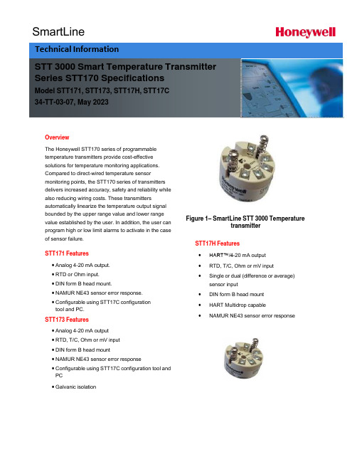
SmartLineOverviewThe Honeywell STT170 series of programmabletemperature transmitters provide cost-effectivesolutions for temperature monitoring applications.Compared to direct-wired temperature sensormonitoring points, the STT170 series of transmittersdelivers increased accuracy, safety and reliability while also reducing wiring costs. These transmittersautomatically linearize the temperature output signalbounded by the upper range value and lower range value established by the user. In addition, the user can program high or low limit alarms to activate in the case of sensor failure.STT171 Features• Analog 4-20 mA output.• RTD or Ohm input.• DIN form B head mount.• NAMUR NE43 sensor error response.• Configurable using STT17C configurationtool and PC.STT173 Features• Analog 4-20 mA output• RTD, T/C, Ohm or mV input• DIN form B head mount• NAMUR NE43 sensor error response• Configurable using STT17C configuration tool and PC• Galvanic isolation Figure 1– SmartLine STT 3000 TemperaturetransmitterSTT17H Features•HART™/4-20 mA output•RTD, T/C, Ohm or mV input•Single or dual (difference or average)sensor input•DIN form B head mount•HART Multidrop capable•NAMUR NE43 sensor error responseSTT 3000 Smart Temperature Transmitter Series STT170 SpecificationsModel STT171, STT173, STT17H, STT17C34-TT-03-07, May 2023Technical InformationDimensions (all models)WiringSTT171 STT173Input:Input:RTD, 2-wire RTD, 3-wire RTD, 4-wire TC, internal CJCRTD,2-wire RTD,3-wire Resistance,2-wire Resistance,3-wireTC, external CJC mV Resistance, 2-wire Resistance, 3-wireOutput:2-wire installationResistance, 4-wireOutput:2-wire installationSTT17HThe STT17C configures the STT171, STT173 and STT17H. The intuitive graphical user interface of the STT17C virtually eliminates the need for operator training after installation on a PC. The STT17C includes all software and transmitter interface hardware necessary to configure the STT171, STT173 and STT17H in non-hazardous work environments.WARNING: The STT17C is not approved for use in Hazardous work environments.System Requirements:Windows® 98SE, ME, 2000 and XP with the following recommendations:Memory: 16 MBDisplay resolution: 800 x 600Hard disk space: 12 MB**or 50%of upper range value,whichever is greater***reference temperature24o COPERATING CONDITIONS APPROVALSAmbient temperature, rated……….……-40 to 85o C (-40 to 185o F)Observed Authority requirements:Standard: Humidity……………………………………0 to 95% RH (non-cond.)EMC 2004/108/EC Vibration…………………………………Max 4g over 25 to 100Hz Emmission and immunity ……… EN 61326ATEX94/9/EC…........................................ EN50014,EN50020, ELECTRICAL INPUT SPECIFICATIONS EN502811-1and EN50284 Supply voltage………………………………8to30VDC FM,ASCN…............................................. 3600,3611,3610Power supply voltage effect………………≤0.005%of span per VDC CSA,CAN/CSA ......................................... C22.2No.157,E60079-11, Warm-up time…………………………..….5min UL913Response time(programmable)…………0.33to60sec Ex/I.S.approval:KEMA06ATEX0042X…………………………II1GD,T80o C…T105o C CURRENT OUTPUT SPECIFICATIONS EEx ia IIC T4.T6Signal output range…………………………4to20mA Max.amb.Temperature for T4….................... 85o CUpdate time………………………………… 135msec Max.amb.Temperature for T6….................... 60o CLoad resistance………....……...…………≤(V supply-8)/0.023A Applicable in zone…..................................... 0,1,2,20,21or220to870οFM,applicable in…………………………………IS,CL I,DIV1,Grp.A-D,T4…T6AEx ia IICALARM LEVELS NI,CL I,DIV2,Grp.A-D,T4...T6 Programmable...................................3.5to4mA downscale Entity,FM Installation Drawing No. (50016324)20 to 23 mA upscale CSA, applicable in.....................................IS,CL I, DIV 1, Grp. A-D, T4...T6 NAMUR NE43 Upscale.........................23 mA Ex ia IIC, AEx ia IIC NAMUR NE43Downscale....................3.5mA Entity,Installation Drawing No... (50016326)Ex/I.S.data:U i (max) .................................................... 30 VDCI i (max)...................................................... 120mADCP i (max) .................................................... 0.84WL i (max)..................................................... 10μHC i (max) .................................................... 1.0 nFUo (max) .................................................. 27 VDCIo (max).................................................... 7 mADCPo (max)................................................... 45m WLo(max) ................................................... 35 mHCo (max) .................................................. 90 nFSTT17H-BN Specification*whichever is greater; Total Reference Accuracy = Basic Accuracy + CJ Accuracy (T/C only)**or 50% of upper range value, whichever is greater*** reference temperature 24o COPERATING CONDITIONS APPROVALSAmbient temperature, rated…………...…. -40 to 85o C (-40 to 185o F) Observed Authority requirements: Standard: Humidity……………………………………0 to 95% RH (non-cond.) EMC 2004/108/EC Vibration…………………………………...…Max 4g over 25 to 100Hz Emmission and immunity ……… EN 61326Cold junction accuracy……………………±1.0o C ATEX94/9/EC… .................................................. EN60079-0,EN60079-15 ELECTRICAL INPUT SPECIFICATIONS Ex / I.S. approval:Supply Voltage....................................8 to 35 VDC KEMA 06 ATEX 0043 X..............................II 3 GD, T80o C...T105o C Power supply voltage effect.................. ≤ 0.005% of span per VDC EEx nA [L] IIC T4. T6 Warm-up time....................................30sec Applicable in zone... (2)Response time(programmable)…………1to60sec Max.amb.Temperature for T4…......................... 85o CGalvanic isolation………………………….1500VAC Max.amb.Temperature for T6…......................... 60o CCURRENT OUTPUT SPECIFICATIONS Vmax (V)Signal output range..................................... 4 to 20 mAUpdate time… ............................................. 440 msecLoad resistance(ν)...................................... ≤(V supply -8)/0.023A0 to 1174 νALARM LEVELSProgrammable…........................................ 3.5 to 4 mA downscale20 to 23 mA upscaleNAMUR NE43 Upscale…......................... 23 mANAMUR NE43Downscale…....................... 3.5 mA9STT 3000 Smart Temperature Transmitter STT171 Custom Configuration Data SheetCustomer P.O. NumberLine ItemModel NumberTag Number (max 15 char)Honeywell Sales Order NumberSensor Type:□Pt100□Ni100□OhmsOutput Values:4 mA Value: 20 mA Value: Response time:□o C□o F□Ohms □o C□o F□Ohms(0.33 – 60 sec)Output Limits:□Span (4 to 20 mA)□Max (3.5 to 23 mA)□Specify Low mA, High mA□NAMUR NE 43 (3.8 to 20.5 mA)Sensor Error Action:□Off□Specify mA□NAMUR NE 43 upscale (23 mA)□NAMUR NE 43 downscale (3.5 mA)10STT 3000 Smart Temperature TransmitterSTT173 Custom Configuration Data SheetCustomer P.O. NumberLine ItemModel NumberTag Number (max 15 char)Honeywell Sales Order NumberSensor Type:□Pt100 □Type B T/C Cold Junction Compensation:□Ni100 □Type E T/C □Internal□Type J T/C □External / Pt100Wiring: □Type K T/C □External / Ni100□2-wire □Type L T/C□3-wire □Type N T/C□4-wire □Type R T/C□Type S T/C□ Ohms □Type T T/C□mV □Type U T/C□Type W3 T/C□Type W5 T/COutput Values:4 mA Value: 20 mA Value: Response time:□o C □o C (1 – 60 sec)□o F □o□mV □mV□Ohms □OhmsOutput Limits:□Span (4 to 20 mA)□Max (3.5 to 23 mA)□Specify Low mA, High mA□NAMUR NE 43 (3.8 to 20.5 mA)Sensor Error Action:□Off□Specify mA□NAMUR NE 43 upscale (23 mA)□NAMUR NE 43 downscale (3.5 mA)STT17H Custom Configuration Data SheetCustomer P.O. NumberLine ItemModel NumberTag Number (max 15 char)Honeywell Sales Order NumberSensor Input:□Single Sensor□Duplex Sensor (Average)□Duplex Sensor (Differential)Sensor Type:□Pt100□Type B T/C Cold Junction Compensation:□Ni100□Type E T/C□Internal□Type J T/C□External / Pt100 Wiring: □Type K T/C□External / Ni100□2-wire□Type L T/C□3-wire□Type N T/C□4-wire□Type R T/C□Type S T/C□Ohms□Type T T/C□mV□Type U T/C□Type W3 T/C□Type W5 T/COutput Values:4 mA Value: 20 mA Value: Response time:□o C□o F□mV □Ohms □o C□o□mV□Ohms(1 – 60 sec)Output Limits:□Span (4 to 20 mA)□Max (3.5 to 23 mA)□Specify Low mA, High mA□NAMUR NE 43 (3.8 to 20.5 mA)Sensor Error Action:□Off□Specify mA□NAMUR NE 43 upscale (23 mA)□NAMUR NE 43 downscale (3.5 mA)Model Selection Guide (34-44-16-07)Model Selection Guides are subject to change and are inserted into the specifications as guidance only.Sales and ServiceFor application assistance, current specifications, pricing, or name of the nearest Authorized Distributor, contact one of the offices below.ASIA PACIFICHoneywell Process Solutions, (TAC) hfs-tac-********************* AustraliaHoneywell LimitedPhone: +(61) 7-3846 1255FAX: +(61) 7-3840 6481Toll Free 1300-36-39-36Toll Free Fax:1300-36-04-70China – PRC - Shanghai Honeywell China Inc.Phone: (86-21) 5257-4568Fax: (86-21) 6237-2826 SingaporeHoneywell Pte Ltd.Phone: +(65) 6580 3278Fax: +(65) 6445-3033South KoreaHoneywell Korea Co LtdPhone: +(822) 799 6114Fax: +(822) 792 9015 EMEAHoneywell Process Solutions,Phone: + 80012026455 or+44 (0)1344 656000Email: (Sales)***************************or(TAC)*****************************AMERICA’SHoneywell Process Solutions,Phone: (TAC) 1-800-423-9883 or215/641-3610(Sales) 1-800-343-0228Email: (Sales)***************************or(TAC)*****************************For more informationTo learn more about Temperature Transmitters,visit Or contact your Honeywell Account ManagerProcess SolutionsHoneywell1250 W Sam Houston Pkwy S Houston, TX 77042Honeywell Control Systems Ltd Honeywell House, Skimped Hill Lane Bracknell, England, RG12 1EB Shanghai City Centre, 100 Jungi Road Shanghai, China 20061 34-TT-03-07May 2023©2023 Honeywell International Inc.。
霍尼韦尔压力变送器
霍尼韦尔(honeywell)美国霍尼韦尔(honeywell)ST3000/900系列全智能变送器*Honeywell- HoneywellST3000 系列变送器(备有现货,优势价格,项目协作)差压型号:STD924 STD930 STD974 STD904微差压:STD120 STD110 STD130 STD170 STD125压力型号:STG944,STG974 ,STG94L ,STG97L,STG98L ,STG99L单法兰:STF924 STF932 STF92F STF93F双法兰:STR93D STR94G霍尼韦尔绝压型号:STA922 STA940 STA92L STA94L温度变送器:STT171 STT173 STT250SFC智能手操器STS103-001-00006-24常用型号: 霍尼韦尔差压变送器的型号有以下等:STD924-A1A-00000-MB,SM,1C (0-100KPa)STD924-E1A-00000-AN,MB,SM,1C (0-100KPa)STD924-E1H-00000-MB,S2,SM,1C (0-100KPa)STD930-A1A-00000-MB,SM,1C (0-700KPa)STD930-E1A-00000-MB,SM,1C (0-700KPa)STD930-E1H-00000-S2,MB,SM,1C (0-700KPa)STD924霍尼韦尔差压变送器 霍尼韦尔压力变送器 ST3000STD930STG944/974 霍尼韦尔压力变送器STG944(0~140 至 0~3500kPa)STG974(0~2.1 至 0~21MPa)常用型号: 霍尼韦尔压力变送器的型号有以下等:STG944-A1A-00000-SM,MB,1C (0~140 至 0~3500kPa)STG944-E1A-00000-SM,MB,1C (0~140 至 0~3500kPa)STG944-E1G-00000-S2,SM,MB,1C (0~140 至 0~3500kPa)STG944-A1G-00000-S2,SM,MB,1C (0~140 至 0~3500kPa)STG974-A1A-00000-SM,MB,1C (0~2.1 至 0~21MPa)STG974-E1A-00000-SM,MB,1C (0~2.1 至 0~21MPa)1)4~20mA标准的制定者,全球第一台智能变送器的提供者2)真正的全量程精度达到0.075%,而非其它厂家标称的参考精度0.075%;这一点得益于霍尼韦尔所独有的复合传感器技术;3)最小的耐静压值为21Mpa(STD110与远传法兰除外);4)任何一台霍尼韦尔变送器均可满足最严格的防爆要求,防爆要求不需另加价;5)负载能力高达1440欧姆……Honeywell压力变送器ST3000系列包含了差压,绝压,表压,微差压,远传法兰,和液位变送器一系列完整的产品。
Thermaltake TG ARGB 170 用户手册说明书
Divider 170 TG ARGB Specification
Case Type
Micro Case
Dimension (H*W*D) 426 x 210 x 408.5 mm (16.8 x 8.3 x 16.1 inch)
Side Panel
Tempered Glass x 1
Material Cooling System
SPCC
Front (intake): 120 x 120 x 25 mm ARGB PWM fan (1500 rpm, 27.2 dBA) x 2
Drive Bays Expansion Slots Motherboards I/O Port PSU Fan Support
Radiator Support
PSU max length: 200mm
Remove Components Divider 170 TG ARGB
208mm
178mm
05
06
Divider 170 TG ARGB Power Supply Unit Installation
Motherboard Installation Divider 170 TG ARGB
30
Stand #6-32 x 5 mm
12
Stand #6-32 x 10 mm
2
Stand #6-32 x 28 mm
13
Buzzer
1
PCI Leaf
2
Cable Ties
10
Use For Power Supply / VGA Card Motherboard Stand-off installation
Front Top Rear Front Top Rear
一体化温度变送器,法兰或焊接 (2)
TI260T/28/zh/07.09技术资料Omnigrad M TR15RTD 热电阻一体化温度变送器,带延长颈和棒材热保护套管法兰连接或焊接应用•应用范围广泛•特别适用于高过程压力和高过程温度的蒸汽和气体测量•测量范围:-200...600 °C (-328...1112 °F)•带焊接热电阻压力等级可达400 bar (5800 psi) •防护等级可达IP 68模块化温度变送器相比于不经过温度变送器而直接接线的测量方法,Endress+Hauser 能为用户提供高测量精度、高测量可靠性的温度变送器。
根据实际工况条件,可以选择下列信号输出和通信方式:•4...20 mA 模拟量输出•HART ®•PROFIBUS ® PA•基金会现场总线(FF™)优势•高灵活性:一体式结构设计、标准接线盒和用户自定义插入深度•高兼容性:设计符合DIN 43772标准•模块化温度变送器自带热保护套管•缩径型或锥管型的热保护套管响应时间短•防爆认证,可在危险区域中使用:- 本安型(Ex ia)- 防火花型(Ex nA)4 0Omnigrad M TR152Endress+Hauser功能与系统设计测量原理热电阻采用符合IEC 60751标准的Pt100温度传感器。
温度传感器为温度敏感性铂热电阻。
0 °C (32 °F) 时,阻抗为100 Ω,温度系数为α = 0.003851 °C -1。
通常,有两种不同类型的铂热电阻:•绕线式(WW):由两根极细的高纯度铂丝在陶瓷载体内绕制而成,并通过陶瓷保护层在载体顶部和底部对铂丝进行密封处理。
此类热电阻具有高可重现性,过程温度高达600 °C (1112 °F)仍能保证良好的阻抗-温度关系的长期稳定性。
相比于薄膜式(TF)热电阻,绕线式(WW)热电阻的体积较大,抗振性较差。
•薄膜式铂电阻温度计(TF):在真空状态下,将厚度约为1 μm 的超高纯度铂层汽化固定到陶瓷基板上光刻制作而成。
Honeywell STT3000-250系列智能温度变送器 说明书(1)

4-20mA、DE 通讯协议或 HART 通讯协议 0 至 102 秒数字式阻尼可调 1 秒内可达到变化值的 63%(阻尼为 0 秒) 约 0.5 秒 可承受 1 分钟的 500Vac 绝缘强度测试 用户可选择对传感器回路开路的测试,并可选择输出最大或最小,联锁或解锁 120db(1,000,000:1)50Hz~50kHz 40db(100:1)50Hz 或 60Hz±0.5Hz 符合 EMC 规范 89/336/EEC 有屏蔽电缆或金属外壳时,为满量程的±0.1%(30v/m,20-1000MHz)
仪表安装方式: 只有模块(无表壳),DIN 轨道安装或墙装 直接安装在较小的传感器头部外壳内 现场安装在隔爆表壳内,远离或直接接到传感器
STT25M STT25H STT25S STT25D STT25T
表 I - 无选择
无选择
0
••• ••• ••• ••• ••• •••
表 II - 表壳和一体化指示表
52
29.2 50
图13-1 STT250 外型尺寸(mm)
白色
白色
白色
白色
红色
RTD
红色 RTD
红色
RTD
红色
红色
二线制RTD 三线制RTD 四线制RTD 或两线制欧姆 或三线制欧姆 或四线制欧姆
图13-2 STT250 接线图
33
单路热电隅
3
STT3000/250 系列智能温度变送器
±0.30℃ 对于 -200~1370℃ 0.025% ±0.45℃ 对于 -200~1370℃
±0.20℃ 对于 0~1300℃
0.025% ±0.75℃ 对于 -200~1300℃
±0.30℃ 对于 500~1760℃
TBC2800 Product Handbook_CN_v5(1)
燃烧器正常启动后,在启动安全时间T2之内控制器没有检测 到火焰信号,就会出现故障锁定,故障信号输出端子12与13 闭合。在整个启动安全时间T2中,燃气阀是打开状态。LED 闪烁显示故障代码“2”。
3、火焰模拟
收到启动信号后,在等待时间T1进行火焰模拟检测。
如果启动过程中的火焰模拟检测到火焰信号,控制器就会进 入火焰模拟延迟时间T5。如果在火焰模拟延迟时间T5内火焰 信号消失,燃烧器就会进入正常启动程序。否则,进入故障 锁定状态,同时LED闪烁显示故障代码“1”。
4、火焰故障熄灭后自锁或重启
通过控制面板的设定 ,决定燃烧器在火焰故障熄灭后是立 即自锁或是重启一次。初始设定为故障后立即自锁。
1、火焰故障熄灭后自锁 通过控制面板设定为故障后自锁
LED 代码显示 3
端子1电源输入 端子5工作信号输入
端子14点火输出 端子15电磁阀输出 端子7(8)火焰信号输入 17、18有火信号输出 12、13故障报警输出 <2S
产品详细说明 特
点:
集成离子棒和UV火检方式,可通过设定切换 六种运行参数集成可选配置 24小时连续运行(UV除外),运行寿命超过25万次(注1) IP54保护等级,适合现场或机柜安装 多功能按键组合,LED 状态指示灯组合
运行状态、故障信息和火焰强度实时显示; 远程或现场复位; 可调节的火焰门槛值 符合欧洲EN298标准
3 T3
运行过程中出现火焰故障,控制器在T3时间内进入故障锁定 状态,同时燃气阀关闭,故障信号输出端子12与13闭合, LED闪烁显示故障代码“3”。
2、火焰故障熄灭后自动重启一次
通过控制面板设定为故障后自动重启
LED 代码显示 3
Honeywell CT3600 CT3697 七天编程可编程温度调节器说明书
69-1642OWNER’S GUIDE® U.S. Registered Trademark Copyright © 2002 Honeywell ••All Rights ReservedHoneywell CT3600/CT3697PROGRAMMABLE THERMOSTATSeven Day Programmable Heat and/or CoolLow Voltage (20 to 30 Vac) Thermostat and Wallplate Model CT3600/CT3697Para obtener un documento con las instrucciones en español, por favor visite nuestro sitio de web a: /yourhome.Pour obtenir des notices techniques en français, veuillez consulter notre site web /yourhome.ContentsStep 1. Prepare for Installation ...................................................................................................................................5Step 2. Remove Old Thermostat ................................................................................................................................6Step 3. Mount Thermostat Wallplate ..........................................................................................................................7Step 4. Wire Wallplate Terminals ................................................................................................................................8Step 5. Install the Batteries .........................................................................................................................................9Step 6. Set Fan Operation Switch ..............................................................................................................................10Step 7. Mount the Thermostat ....................................................................................................................................11Step 8. Customize Your Thermostat ...........................................................................................................................11Step 9. Set the Clock ..................................................................................................................................................13Step 10. Programming ................................................................................................................................................14Step 11. Operating Your Thermostat ..........................................................................................................................17Step 12. Set the Fan and System Switches ...............................................................................................................19If You Have a Problem ................................................................................................................................................20Smart Response™ Technology ..................................................................................................................................21Wiring Diagrams (22)Total comfort temperature management with Smart Response™ Technology.Congratulations! You made a smart choice by purchasing your new Honeywell thermostat; the smart thermostat that;•Keeps you comfortable by automatically calculating exactly when the furnace or air conditioning should go on to have the house at the desired comfort temperature by the time you wake up or return home.•Saves the maximum amount of energy and money by automatically remembering to adjust the temperature when you leave home or go to sleep.•Provides the ultimate in comfort and convenience. It comes preprogrammed. You can use the preprogrammed schedule, or set your own.This manual answers many of the questions that can arise as you become familiar and comfortable with your Honeywell thermostat — the state of the art in home comfort controls.Read these instructions carefully. Failure to follow these instructions can damage the product or cause a hazardous condition.69-16422369-164269-16424569-1642STEP 1. PREPARE FOR INSTALLATION❑Check Table 1, the compatibility chart, to make sure the thermostat is compatible with your system. If your systemis not compatible, call Honeywell Customer Relations Center, toll-free, 1-800-468-1502.Table 1. Compatibility Chart.aCompatible with 2-wire Honeywell and Taco zone valves. Not compatible with 3-wire zone valves or 2-wire White Rodgers no. 1361 zone valves.b Millivolt system must be heating only.cNot compatible with any 120/240 volt system.Package Contents•Thermostat •Wallplate•Screws and anchors•Wiring labels •Owner’s GuideTools Required•Screwdriver •DrillSystem TypeCompatibility with CT3600/CT3697Gas — Standing Pilot Yes Gas — Electronic Ignition Yes Gas-fired BoilersYes a Gas — 750 Millivolt Heat only b Yes Oil-Fired Boilers Yes a Oil-Fired Furnace Yes Electric Furnace Yes Electric Air ConditioningYes Baseboard Electric (120/240 line volt)c No Single Stage Heat PumpYes Multistage Heat Pumps/Multistage EquipmentNoSTEP 2. REMOVE OLD THERMOSTAT❑Test your heating and cooling systems to make sure they work properly. If either system does not work, contact your local heating/air-conditioning dealer. To avoid compressor damage, do not operate the cooling system when outdoor temperature is below 50°F (10°C).❑Turn off power to the system at the furnace or the fuse/circuit breaker panel.❑Carefully unpack your new thermostat and wallplate. Save package of screws, instructions, and receipt.❑Remove the cover from the old thermostat. If the cover does not snap off when pulled firmly from the bottom, check for a screw or screws used to lock on the cover.❑Loosen the screw or screws holding the thermostat to the wallplate and lift the thermostat away.❑Disconnect the wires from the old thermostat. As you disconnect each wire, attach the enclosed labels with the old terminal designation. If there are only two wires, they do not need to be labeled. Wrap the wires around a pencil as shown to keep them from falling back into the wall.Special Installations Array Read this section if you are replacing:•Clock thermostat with separate wires for the clock.•Thermostat with six or more wires connected to it.•Thermostat in a heating only system with three wires.Replacing a Clock Thermostat that has C or C1 Clock TerminalsIf you are replacing a Honeywell Chronotherm®Thermostat, you may find one or twowires going to the C or C1 clock terminals on the Chronotherm wiring wallplate. Do not allow them to touch, or you can damage the transformer. Disconnect the wires and wrap them separately using electrical tape. Do not wrap them together. Place the wires where they will not interfere with the operation of the new thermostat. Record the colors and terminal designation labels of the remaining wires.Replacing a Thermostat that has Six or More WiresIf there are six or more wires (excluding clock wires attached to terminals), you probably have a variation of a multistage heat pump or other multistage system. This thermostat is not compatible with multistage systems, so return the product to the place of purchase. For information about which programmable thermostats will work with your system, call Honeywell Customer Relations Center, at 1-800-468-1502.Replacing a Thermostat that has Three WiresIf you have three wires for a heating only system and can operate the fan using the fan ON switch this thermostat works with your system. However, some hot water (zoned) heating systems also have three wires. Your thermostat willwork only if you install an isolating relay on these systems. For details, call your local heating and/or cooling contractor.69-16426STEP 3. MOUNT THERMOSTAT WALLPLATE❑Separate the wallplate from the thermostat by placing your thumb or fingers between the bottom of the wallplate and the thermostat, and pulling thewallplate up and away from the thermostat. See illustration at right.❑Position the wallplate on the wall. Level the wallplate for appearance if desired.Use a pencil to mark the two mounting holes that best fit the application.❑Remove the wallplate from the wall. Drill two 3/16 in. holes in wall (if drywall) as shown. For materials such as plaster or wood, drill 7/32 in. holes where marked.Gently, tap the (provided) anchors into the drilled holes until they are flush with the wall.❑Reposition the wallplate over the holes. Pull the wires through the wiring opening. Loosely insert mounting screws into each of the holes.❑Level the wallplate if desired. Thermostat functions properly when not level.❑Tighten mounting screws.769-1642STEP 4. WIRE WALLPLATE TERMINALS IMPORTANTAll wiring must comply with local codes and ordinances. Ifunsure about household wiring procedures, call your local heat-ing/air-conditioning contractor.Refer to the labels you placed on the wires when you removed the old thermostat (see illustration).❑Match the letter of your old thermostat wire with the corresponding terminal letter on your new thermostat. Refer to Table 2.❑Remove the factory-installed jumper connecting terminals R and RC if wires are connected to both of those terminals.❑For wiring diagrams, if needed, see pp 22-23.❑Loosen the terminal screws. Slip each wire beneath its matching terminal. Wraparound and straight connections are both acceptable, (see illustration). Tighten the terminals.❑Plug the hole in the wall with insulation to help prevent drafts from adversely affecting thermostat operation.69-16428969-1642Table 2. Terminal Designations on Old and New Thermostatsa If both RH and R terminals are present on existing thermostat, remove jumper and connect Rh to R and R to Rc.b Do not connect both O and B when wiring to a single stage heat pump. Connect O to O. Tape off B.cTape off end of the wire with electrical tape and push the taped wire back into the wiring hole in the wall.STEP 5. INSTALL THE BATTERIESIMPORTANTInstall three AA alkaline batteries. Batteries must beinstalled for programming and operation of the thermostat and the heating/cooling system.❑Install the batteries in the wallplate so the positive terminals allpoint up (see illustration).❑If the thermostat is already mounted on the wall, remove thethermostat by placing your thumb between the thermostat and wallplate and pulling the thermostat up and away as shown.Terminal on Old Thermostat Connect ToDescriptionR, RH a , 4, V R PowerRc, R a Rc Power for cooling W, W 1, H W Heat Y , Y 1, M Y Cooling G, F G FanO O Changeover in cool. (Single stage heat pump only).B bB bChangeover in heat. (Single stage heat pump only).C c , X c , B b Do not connect.Transformer commonW 2, H 2Do not continue installation. Call 1-800-468-1502.Second stage heat.Y 2Second stage cool.69-164210When the batteries are running low, a REPL BAT message flashes for one to two months before the batteries run out completely. Replace the batteries as soon as possible once the message flashes.IMPORTANTAlthough the thermostat has a low battery indicator, replace the batteries once per year to prevent leakage and to prevent the ther-mostat and heating/cooling system from shutting down due to lack of battery power in the thermostat.If you insert new batteries within 20 to 30 seconds of removing the oldbatteries, the system retains the current time and day. If the display is blank, the batteries are dead or installed incorrectly. You must reset the time and day. Refer to Set the Clock for instructions.As a precaution when leaving home for longer than a month, change batteries before leaving to prevent the system from shutting down due to lack of power. Always use fresh alkaline batteries. Nonalkaline batteries do not last as long. They also can leak, causing damage to the thermostat and the wall surface.The thermostat fan operation switch, labeled FUEL SWITCH is factory set in the F position. This is the correct setting for most systems. If your system is an electric heat system, set the switch to E. The E setting allows the fan to turn on immediately with the heating and cooling in a system where the G terminal is connected.1169-1642STEP 7. MOUNT THE THERMOSTATSTEP 8. CUSTOMIZE YOUR THERMOSTATYour Honeywell CT3600/CT3697 Thermostat comes preset to the most commonly used settings. The settings are:—Gas or oil forced air furnace.—Smart Response technology on.—Temperature °F.—12-hour clock format.You can change any or all of these settings.IMPORTANTAlways press the keys with your fingertip or a similar blunt tool. Sharp instruments like pens and pencil points can damage the keyboard.❑, and , simultaneously until the screen shows.You now can change any of these settings.System Type (Feature Number 4)System type options are:—1 = Gravity or steam system.—3 = Hot water, high efficiency furnace (90% or better), or single stage heat pump.—6 = Gas or oil forced air furnace (preset).—9 = Electric furnace.To change your system type:❑❑ to move to next feature or to return to main display.Smart Response™ Technology (Feature Number 13) Smart Response technology options are:—0 = Smart Response technology on (preset).—1 = Smart Response technology off.To turn Smart Response technology on or off:❑❑to move to next feature or to return to main display.NOTE:See Smart Response technology (page 21) for information about this feature.Temperature Format (Feature Number 14) Temperature format options are:—0 = °F (preset).—1=°C.To change temperature format:❑❑to move to next feature or to return to main display.Time Format (Feature Number 16) Time format options are:—0 = 12-hour clock (preset).—1 = 24-hour clock.Run ProgramRun ProgramRun Program69-164212To change time format:❑❑to return to main display.Factory Set Function (Feature Number 37)Do not change this setting.STEP 9. SET THE CLOCKSet Current Day and TimeNOTE:On initial power-up, the screen flashes 1:00 pm until you press a key.❑❑❑❑❑1369-164269-164214STEP 10. PROGRAMMINGThe keyboard is located behind the thermostat cover. The three most frequently used keys are near the display.Pressing displays the current temperature settings. Pressing thethermostat displays day, time, program period, temperature and system settings.There is an individual key for each of the four program periods:get ready for work or school. (This is a higher temperature during the heating season and a lower temperature during the cooling season).(This is a lower temperature during the heating season and a higher temperature during the cooling season).(This is a higher temperature during the heating season and a lower temperature during the cooling season).temperature during the heating season and a higher temperature during the cooling season.)1569-1642Table 3 can be helpful when planning your schedule of time and temperature settings. The thermostat default settings are shown in parentheses ( ).Table 3. Personal Programming Table.a Your heating setpoints cannot be higher than 90°F (32°C) or lower than 40°F (4.5°C).bYour cooling setpoints cannot be higher than 99°F (37°C) or lower than 45°F (7°C).Program the First DayStart by programming the wake time and temperature for one day.❑❑❑Period Default Setting Monday (Mon)Tuesday (Tue)Wednesday (Wed)Thursday (Thu)Friday(Fri)Saturday (Sat)Sunday (Sun)WakeTime (6:00AM)Heat a (70°F/21°C)Cool b (78°F/25.5°C)LeaveTime (8:00AM)Heat a (62°F/16.5°C)Cool b (85°F/29.5°C)ReturnTime (6:00PM)Heat a (70°F/21°C)Cool b (78°F/25.5°C)SleepTime (10:00PM)Heat a (62°F/16.5°C)Cool b (82°F/28°C)69-164216NOTE:Program times are in 15 minute intervals. For example, 8:00, 8:15, 8:30.❑The setpoint temperature range is 40°F to 90°F (4.5°C to 32°C) for heating and 45°F to 99°F (7°C to 37°C) for cooling.❑NOTE:Program times are the same for heating and cooling.❑❑and repeat these steps for each program period. The First Day is now❑Repeat each step in Program the First Day for the rest of the week. NOTE:After the first day is programmed, you can copy that day to any other day using procedure in Copy a Day.❑Presswhen the entire week is programmed.Copy a DayYour thermostat can copy program settings from one day to another.❑to enter programming mode.❑until the display shows the day you want to copy.❑Run Program1769-1642❑❑Pressto accept the change.❑Repeat these steps for each day you want to copy.NOTE:donE appears for two seconds and then the normal program display appears.Clear a Program PeriodNOTE:Wake cannot be cleared.❑❑until the desired day displays.❑for approximately 3 seconds until the time and temperature clear.❑Repeat the above steps for each period to be cleared.❑Press .STEP 11. OPERATING YOUR THERMOSTATChange Temperature Setting Until the Next Program Period (Temporary Change)❑NOTE:The temporary temperature setting is displayed for about 3 seconds and then the room temperature is dis-played. Temporary appears in the display. The setting cancels when the next program period starts or when you press.CopyRunProgram RunProgram69-164218Change Temperature Setting Indefinitely (Hold)❑Move the System switch to the desired position (Heat or Cool).❑Press to change your setting if desired. (The display changes from showing the setpointtemperature to room temperature after approximately three seconds).❑To cancel “Hold” press.Change the Temperature Setting Until a Designated Day and Period (Vacation Hold)❑❑❑❑to select the program period when you want the program to restart.NOTE:If the Vacation Hold needs to be cancelled before the designated time, press to return to theprogram.Daylight Savings Time KeyThis feature allows you to switch between standard time and daylight savings time. ❑❑time. NOTE:Pressing the Daylight Time key more than once in a five minute period scrolls you through various time options. For example, one hour earlier or later, with or without DST. Pressing Daylight Time six times in a five minute period returns you to your original setting.Run RunProgram1969-1642Usage Key❑❑❑NOTE:STEP 12. SET THE FAN AND SYSTEM SWITCHESFirst set the fan switch.Fan On: The fan runs continuously. Use for improved air circulation or for more efficient central air cleaning. (In a heat-only system, fan runs continuously only if fan relay is connected to the G thermostat terminal).Fan Auto: Normal setting for most homes. The equipment controls the fan operation.Then set the system switch.Heat: The thermostat controls your heating system.Off: Both the heating and air conditioning systems are off.Cool: The thermostat controls your air conditioning system.IF YOU HAVE A PROBLEMTable 4. Solution Guide.69-164220Customer AssistancePlease read and follow the provided instructions for this thermostat. For additional information, go to/yourhome or call our 24-hour automated information line at 1-800-468-1502.Before calling, please have the following information available:•Thermostat model number. (Located on back of thermostat).•Thermostat date code. (Located below model number).•Type of heating/cooling system (for example, hot water, warm air, oil, or gas).•Location and number of wires connected to the thermostat.SMART RESPONSE™ TECHNOLOGYYour CT3600/CT3697 is actually a small computer. The Smart Response technology calculates the correct time of day to turn on your heating or cooling system. Smart Response technology considers the following information.•Air temperature.•Wall temperature.•The time of day when you want the comfort temperature established.When the thermostat activates Smart Array Response technology, the thermostatdisplays In Recovery, changes thesetpoint, and turns on the system.•Your CT3600/CT3697 Thermostatlearns from experience. Each day itchecks how closely it hit the recoverytarget and then adjusts the next day’srecovery start time accordingly.•It takes a few days after installation forthe thermostat to adjust to the localweather, your lifestyle, the constructionof your home, and your heating/coolingsystem.•You can turn off Smart Responsetechnology by selecting ConventionalRecovery. See Step 8. Customize YourThermostat.2169-1642WIRING DIAGRAMS69-1642222369-1642Notice:This thermostat is a Class B digital apparatus that complies with Canadian Radio Interference Regulations,CRC c.1374.69-1642 G.H. /yourhomeAutomation and Control SolutionsHoneywellHoneywell Limited-Honeywell Limitée 1985 Douglas Drive North 35 Dynamic Drive Golden Valley, MN 55422Scarborough, Ontario M1V 4Z9Limited One-Year WarrantyHoneywell warrants this product, excluding battery, to be free from defects in the workmanship or materials, under normal use and service, for a period of one (1) year from the date of purchase by the consumer. If, at any time during the warranty period, the product is defective or malfunctions, Honeywell shall repair or replace it (at Honeywells option) within a reasonable period of time.If the product is defective,(i)return it, with a bill of sale or other dated proof of purchase, to the retailer from which you purchased it, or(ii)package it carefully, along with proof of purchase (including date of purchase) and a short description of the malfunction, and mail it, postageprepaid, to the following address:Honeywell USA Honeywell Canada:Dock 4 — MN10-3860Honeywell Limited/Honeywell Limitée 1885 Douglas Drive North 35 Dynamic Drive Golden Valley, MN 55422-3992Scarborough, Ontario M1V 4Z9This warranty does not cover removal or reinstallation costs. This warranty shall not apply if it is shown by Honeywell that the defect ormalfunction was caused by damage which occurred while the product was in the possession of a consumer.Honeywells sole responsibility shall be to repair or replace the product within the terms stated above. HONEYWELL SHALL NOT BE LIABLE FOR ANY LOSS OR DAMAGE OF ANY KIND, INCLUDING ANY INCIDENTAL OR CONSEQUENTIAL DAMAGESRESULTING, DIRECTLY OR INDIRECTLY FROM ANY BREACH OF ANY WARRANTY , EXPRESS OR IMPLIED, OR ANY OTHER FAILURE OF THIS PRODUCT. Some states do not allow the exclusion or limitation of incidental or consequential damages, so this limitation may not apply to you.THIS WARRANTY IS THE ONLY EXPRESS WARRANTY HONEYWELL MAKES ON THIS PRODUCT. THE DURATION OF ANY IMPLIED WARRANTIES, INCLUDING THE WARRANTIES OF MERCHANTABILITY AND FITNESS FOR A PARTICULAR PURPOSE, IS HEREBY LIMITED TO THE ONE YEAR DURATION OF THIS WARRANTY . Some states do not allow limitations on how long an implied warranty lasts, so the above limitation may not apply to you.This warranty gives you specific legal rights, and you may have other rights which vary from state to state.If you have any questions concerning this warranty, please write Honeywell Customer Relations, 1885Douglas Dr. N., Golden Valley, MN 55422-3992. In Canada, write Retail Products ON30 Honeywell Limited/Honeywell Limitée, 35 Dynamic Drive, Scarborough, Ontario M1V 4Z9.。
霍尼韦尔压力变送器

霍尼韦尔(honeywell)美国霍尼韦尔(honeywell)ST3000/900系列全智能变送器*Honeywell- HoneywellST3000 系列变送器(备有现货,优势价格,项目协作)差压型号:STD924 STD930 STD974 STD904微差压:STD120 STD110 STD130 STD170 STD125压力型号:STG944,STG974 ,STG94L ,STG97L,STG98L ,STG99L单法兰:STF924 STF932 STF92F STF93F双法兰:STR93D STR94G霍尼韦尔绝压型号:STA922 STA940 STA92L STA94L温度变送器:STT171 STT173 STT250SFC智能手操器STS103-001-00006-24常用型号: 霍尼韦尔差压变送器的型号有以下等:STD924-A1A-00000-MB,SM,1C (0-100KPa)STD924-E1A-00000-AN,MB,SM,1C (0-100KPa)STD924-E1H-00000-MB,S2,SM,1C (0-100KPa)STD930-A1A-00000-MB,SM,1C (0-700KPa)STD930-E1A-00000-MB,SM,1C (0-700KPa)STD930-E1H-00000-S2,MB,SM,1C (0-700KPa)STD924霍尼韦尔差压变送器 霍尼韦尔压力变送器 ST3000STD930STG944/974 霍尼韦尔压力变送器STG944(0~140 至 0~3500kPa)STG974(0~2.1 至 0~21MPa)常用型号: 霍尼韦尔压力变送器的型号有以下等:STG944-A1A-00000-SM,MB,1C (0~140 至 0~3500kPa)STG944-E1A-00000-SM,MB,1C (0~140 至 0~3500kPa)STG944-E1G-00000-S2,SM,MB,1C (0~140 至 0~3500kPa)STG944-A1G-00000-S2,SM,MB,1C (0~140 至 0~3500kPa)STG974-A1A-00000-SM,MB,1C (0~2.1 至 0~21MPa)STG974-E1A-00000-SM,MB,1C (0~2.1 至 0~21MPa)1)4~20mA标准的制定者,全球第一台智能变送器的提供者2)真正的全量程精度达到0.075%,而非其它厂家标称的参考精度0.075%;这一点得益于霍尼韦尔所独有的复合传感器技术;3)最小的耐静压值为21Mpa(STD110与远传法兰除外);4)任何一台霍尼韦尔变送器均可满足最严格的防爆要求,防爆要求不需另加价;5)负载能力高达1440欧姆……Honeywell压力变送器ST3000系列包含了差压,绝压,表压,微差压,远传法兰,和液位变送器一系列完整的产品。
Honeywell ST 3000 Smart Transmitter 型号 STG14T 产品说明
ST 3000 Smart TransmitterSeries 100 High Temperature GP ModelsSTG14T, STF14T 0-500 psig / 0-35 barg34-ST-03-707/04Specification and Model SelectionGuideIn 1983, Honeywell introduced the first Smart Pressure Transmitter ― the ST 3000®. In 1989, Honeywell launched for smart field devices. Today, Honey-well transmitters demonstrate proven reliability in hundreds on installations in a wide variety of industries and applica-tions. For applications requiring direct connection to processes requiring small flange, small sanitary connec-tions or 1/2” NPT, Honeywell offers the STG14T transmitter. Applications in-clude gauge pressure for reaction ves-sels in the chemical industry as well as level applications in both the chemical and hydrocarbon processing industries with a relatively high process tempera-ture of 302F (150C). Applications for the food and pharmaceutical industries typically use sanitary connections and M-20 fill fluid.All ST 3000 transmitters can provide a 4-20 mA output, Honeywell Digitally Enhanced (DE) output, HART * output, or F OUNDATION ™ Fieldbus output. When digitally integrated with Honey-well’s Process Knowledge System™, EXPERION PKS™, ST 3000 instru-ments provide a more accurate proc-ess variable as well as advanced diag-nostics.S100 transmitters lead the industry in: • Accuracy • Stability • Reliability • Rangeability • WarrantyIncludes Lifetime Tranmsitters: • Accuracy = +/-0.0375%• Stability = +/-0.01% per year • Reliability = 470 years MTBF • Rangeability = 400 to 1• Lifetime Warranty = 15 yearsFigure 1—Series 100 High Temperature GP Transmitters feature proven pie-zoresistive sensor technology.The devices provide comprehensive self-diagnostics to help users maintain high uptime, meet regulatory requirements, and attain high quality standards. S100 transmitters are ideal for critical applications, such as custody transfer of natural gas and energy and material bal-ances, where accuracy and stability are of the utmost importance."Our commitment to Honeywell field instruments is based on seam-less integration with our Honeywell system and the enhanced fault detection that the Honeywell DE protocol offers. Honeywell instru-ments also offer us a better way of ensuring database integrity over simple analog instruments. In addition, Honeywell's high-quality sup-port has enabled us to better implement solutions to some of ourmore difficult problems. We have used Honeywell differential pressure smart transmitters for the past eight years. Based on their accuracy and low failure rates, we are now targeting critical flow applications that require the robustness that these transmitters bring.” DCS Systems EngineerInternational Integrated Oil CompanyIntroduction34-ST-03-70 Page 2Description FeaturesThe ST 3000 transmitter can replace any 4 to 20 mA output transmitter in use today and operates over a standard two-wire system.The measuring means is a piezoresistive sensor, which actually contains three sensors in one. It contains a differential pressure sensor, a temperature sensor, and a static pressure sensor.Microprocessor-based electronics provide higher span-turndown ratio, improved temperature and pressure compensation, and improved accu-racy.The transmitter’s meter body and electronics housing resist shock, vibra-tion, corrosion, and moisture. The electronics housing contains a com-partment for the single-board electronics, which is isolated from an inte-gral junction box. The single-board electronics is replaceable and inter-changeable with any other ST 3000 Series 100 or Series 900 model transmitter.Like other Honeywell transmitters, the ST 3000 features two-way com-munication between the operator and the transmitter through our Smart Field Configurator (SFC). You can connect the SFC anywhere that you can access the transmitter signal lines.The SCT 3000 Smartline® Configuration Toolkit provides an easy way to configure instruments using a personal computer. The toolkit enables configuration of devices before shipping or installation. The SCT 3000 can operate in the offline mode to configure an unlimited number of de-vices. The database can then be loaded downline during commissioning. • Choice of linear or square root output conformity is asimple configuration selec-tion.• Direct digital integration with Experion PKS and other con-trol systems provides localmeasurement accuracy to thesystem level without addingtypical A/D and D/A converterinaccuracies.• Unique piezoresistive sensor automatically compensatesinput for temperature andstatic pressure.Added “smart”features include configuringlower and upper range val-ues, simulating accurate ana-log output, and selecting pre-programmed engineeringunits for display.• Smart transmitter capabilities with local or remote interfac-ing means significant man-power efficiency improve-ments in commissioning,start-up, and ongoing mainte-nance functions.34-ST-03-70 Page 334-ST-03-70 Page 4Specifications34-ST-03-70Page 5Ambient Temperature De-ratingSilicone Fill Fluid Neobee Fill FluidProcess temperatures above 125 °C (257 °F) require de-rating the ambient limit as follows:Process temperatures above 85 °C (185 °F) require de-rating the ambient limit as follows:Process Temperature Ambient TemperatureLimit Process Temperature Ambient TemperatureLimit150 °C (302 °F) 140 °C (284 °F) 125 °C (257 °F)50 °C (122 °F)60 °C (140 °F)85 °C (185 °F)110 °C (230 °F)100 °C (212 °F)85 °C (185 °F)50 °C (122 °F)60 °C (140 °F)75 °C (167 °F)Performance Under Rated Conditions* -* Performance specifications are based on reference conditions of 25°C (77°F), 10 to 55% RH, and 316L SS diaphragm. ** Transmitter URL limit or maximum process connection rating, whichever is lower.34-ST-03-70Page 6Performance Under Rated Conditions – General for all ModelsParameter Description Output (two-wire) Analog 4 to 20 mA or digital communications DE mode. Options available forF OUNDATION Fieldbus and HART protocol.Supply Voltage Effect ±0.005% span per volt.Damping Time Constant Adjustable from 0 to 32 seconds digital damping.EMC Classification Group 1, Class A, ISM Equipment (EN 55011, emissions), Industrial Equipment (EN50082-2, immunity)CE Conformity (Europe) 89/336/EEC, Electromagnetic Compatibility (EMC) Directive.Lightning Protection Option (Code “LP”) Leakage Current: ***********************,93°CImpulse Rating: 10/20 µ sec. 5,000 Amps (50 strikes) 10,000 Amps (20 strikes) (rise/decay) 10/1000 µ sec. 250 Amps (1000 strikes) 500 Amps (400 strikes)Physical and Approval BodiesParameter Description Process Interface See Model Selection Guide for Material Options for desired process connection.Diaphragm Materials (wetted) 316L Stainless SteelGasket Ring Materials (wetted) 316L Stainless SteelMounting Flange (non-wetted) 316 Stainless Steel.Fill Fluid Silicone (DC 200) or Neobee (M20)Electronic Housing Epoxy-Polyester hybrid paint. Low copper-aluminum alloy. Meets NEMA type 4X(watertight) and designed to meet NEMA 7 (explosion proof).Process Connections Process Head: 1/2-inch NPT.Sanitary: 2” Sanitary Tri-Clamp.Flange: 1/2”, 1”, 1 1/2” and 2” 150# or 300# ANSI flange.Wiring Accepts up to 16 AWG (1.5 mm diameter).Mounting 1/2-inch NPT, sanitary seal, or flange mount connection.Dimensions See Figures 4 to 6Net Weight 7 pounds (3.2 Kg) to 15 pounds (7 Kg)Approval Bodies- Hazardous Areas- Canadian RegistrationNumber (CRN) Approved as explosion proof and intrinsically safe for use in Class I, Division 1, Groups A, B, C, D locations, and nonincendive for Class I, Division 2, Groups A, B, C, D locations. Approved EEx ia IIC T4, T5, T6 and EEx d IIC T5, T6 per ATEX standards. See attached Model Selection Guide for options.- All ST 3000 model designs, except STG19L, STG99L, STG170, STG180, have been registered in all provinces and territories in Canada and are marked CRN: 0F8914.5C.Table continued on next page ⇒34-ST-03-70Page 7Physical and Approval Bodies, continuedParameter DescriptionPressure Equipment Directive (97/23/EC) The ST 3000 pressure transmitters listed in this Specification have no pressurized internal volume or have a pressurized internal volume rated less than 1,000 bar (14,500 psig) and/or have a maximum volume of less than 0.1 liter. Therefore, these transmitters are either; not subject to the essential requirements of the directive97/23/EC (PED, Annex 1) and shall not have the CE mark, or the manufacturer has the free choice of a module when the CE mark is required for pressures > 200 bar (2,900 psig).NOTE: Pressure transmitters that are part of safety equipment for the protection of piping (systems) or vessel(s) from exceeding allowable pressure limits, (equipment with safety functions in accordance with Pressure Equipment Directive 97/23/EC article 1, 2.1.3), require separate examination.Figure 4 Typical mounting dimensions for 1/2-inch NPT connection models for reference.34-ST-03-70 Page 8Figure 5 Typical mounting dimensions for flush sanitary seal connection models for reference.34-ST-03-70Page 9Figure 6 Typical mounting dimensions for small flange connection models for reference.34-ST-03-70 Page 10Options Ordering Information Indicating Meter(ME and SM Options)Two integral meter options are available. An analog meter (option ME) is available with a 0 to 100% linear scale. The Smart Meter (option SM) provides an LCD display for both analog and digital output and can be configured to display pressure in pre-selected engineering units.Lightning Protection (Option LP)A terminal block is available with circuitry that protects the transmitter from transient surges induced by nearby lightning strikes.HART Protocol Compatibility (Option HC)An optional electronics module is available for the ST 3000 that provides HART Protocol compatibility. Transmitters with the HART Option are compatible with the AMS System. (Contact your AMS Supplier if an upgrade is required.)Transmitter Configuration (Option TC)The factory can configure the transmitter linear/square root extraction, damping time, LRV, URV and mode (analog/digital) and enter an ID tag of up to eight characters and scratchpad information as specified. Lifetime Warranty(Option WL)Extends limited 1-year warranty policy to 15 years for ST 3000S100 pressure transmitters. See Honeywell Terms and Conditions.Indicator Configuration(Option CI)Provides custom configuration ofSmart MetersTagging (Option TG)Up to 30 characters can be addedon the stainless steel nameplatemounted on the transmitter’selectronics housing at no extra cost.Note that a separate nameplate onthe meter body contains the serialnumber and body-related data. Astainless steel wired on tag withadditional data of up to 4 lines of 28characters is also available. Thenumber of characters for taggingincludes spaces.Custom Calibration and ID inMemory (Option CC)The factory can calibrate any rangewithin the scope of the transmitter’srange and enter an ID tag of up toeight characters in the transmitter’smemory.F OUNDATION Fieldbus(Option FF)Equips transmitter with FF protocolfor use in 31.25 kbit/s FF networks.See document 34-ST-03-72 foradditional information on ST 3000Fieldbus transmitters.Contact your nearest Honeywell sales office,orIn the U.S.:HoneywellIndustrial Automation & Control16404 North Black Canyon Hwy.Phoenix, AZ 850531-800-288-7491In Canada:The Honeywell Centre155 Gordon Baker Rd.North York, Ontario M2H 3N71-800-461-0013In Latin America:Honeywell Inc.480 Sawgrass Corporate Parkway,Suite 200Sunrise, FL 33325(954) 845-2600In Europe and Africa:Honeywell S. A.Avenue du Bourget 11140 Brussels, BelgiumIn Eastern Europe:Honeywell Praha,s.r.o. Budejovicka 1140 21 Prague 4,Czech RepublicIn the Middle East:Honeywell Middle East Ltd.Khalifa Street,Sheikh Faisal BuildingAbu Dhabi, U. A. E.In Asia:Honeywell Asia Pacific Inc.Honeywell Building,17 Changi Business Park Central 1Singapore 486073Republic of SingaporeIn the Pacific:Honeywell Pty Ltd.5 Thomas Holt DriveNorth Ryde NSW Australia 2113(61 2) 9353 7000In Japan:Honeywell K.K.14-6 Shibaura 1-chromeMinato-ku, Tokyo, Japan 105-0023Specifications are subject to change without notice Or, visit Honeywell on the World WideWeb at: 34-ST-16-47 Issue 14**The user must determine the type of protection required for installation of the equipment. The user shall then check the box [D] adjacent to the type of protection used on the equipment certification nameplate. Once a type of protection has been checked on the nameplate, the equipment shall not then be reinstalled using any of the other certification types.This Page Intentionally BlankST 3000 is a registered trademark of Honeywell International Inc.HART* is a trademark of the Hart Communication Foundation.FOUNDATION™ is a trademark of the Fieldbus Foundation.Industrial Measurement and ControlHoneywell International Inc.2500 W. Union Hill Drive,Phoenix, Arizona 85027 Honeywell International Inc.。
霍尼韦尔DPT系列微差压变送器技术说明书
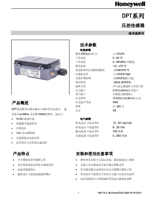
1产品概述技术说明书 HBT -G.C.-Building -FDSS -SEP -2019-CN01 DPT 系列 压差传感器DPT 系列微差压变送器用于测量差压或表压, 提供低至+/-50Pa, 高至0-10kPa 的量程,适用于: ∙ HVAC 暖通空调∙ 智能楼宇能源管理∙ 环境保护∙ VAV 及风阀控制∙ 过滤系统及风扇监控∙ 洁净间压力及管道风速监控产品特点∙ 全不锈钢电容型敏感元件∙ 良好的温度稳定性和长期稳定性∙ 电源误接线保护∙ 翻盖设计方便现场接线和维护技术参数 性能参数 精度(RSS)(恒温下) ±1.0%FS 工作温度 0...50 °C 工作湿度 0...95%RH(不凝露) 储存温度 -10...+70 °C 温度影响(零点/满程偏移) ±0.06%FS/°C 长期稳定性 ±1.0%FS/Year 安装位置影响 ±0.6%FS(最大值) 响应时间 <20ms (63%FS) 测量介质 空气或无腐蚀性不导电气体 压力接口 3/16”(4.8mm)外径接口 电气接口 可插拔式接线端子 外壳材质 聚碳酸酯(UL94V -0 认证) 外壳防护等级 IP65 重量 约 220 克 认证 CE 电气参数 供电电压(电压型) 12...30 Vac/Vdc 供电电压(电流型) 9...30 Vdc 输出阻抗(电压型) 100 欧姆 负载范围(电流型) 0...800 欧姆 安装和使用注意事项 ∙ 推荐垂直安装于无震动表面,避免底面向上倒装 ∙ 安装后可以微调零点电位器以消除误差 ∙ 信号线布线应远离高压及动力线路以避免干扰 ∙ 禁用高压气体清洁气管和压力接口以免过压损坏 ∙ 没有高精度压力基准源时请勿进行满量程调整2霍尼韦尔环境自控产品(天津)有限公司 天津经济技术开发区南海路158号邮编:300457电话:+86-22-66287000传真:+86-22-25325214说明书如有变动,不另行通知。
国际品牌温度传感器介绍一

一、霍尼韦尔公司简介:霍尼韦尔是《财富》百强公司,总部位于美国。
致力于发明制造先进技术以应对全球宏观趋势下的严苛挑战,例如生命安全、安防和能源。
公司在全球范围内拥有大约130,000 名员工,其中包括19,000 多名工程师和科学家。
霍尼韦尔在华的历史可以追溯到1935年。
当时,霍尼韦尔在上海开设了第一个经销机构。
1973年美国总统尼克松访华时,应中国政府之邀从十大领域推荐精英企业来华推动两国双向交流,并促进中国的现代化建设。
其中炼油石化领域唯一被选中推荐给中国政府的美国环球油品公司,正是霍尼韦尔旗下的子公司。
80年代的改革开放成为了霍尼韦尔融入中国经济发展的又一个新起点,作为首批在北京设立代表处的跨国企业,霍尼韦尔在彼时开始了一系列的高品质投资。
目前,霍尼韦尔四大业务集团均已落户中国,旗下所辖的所有业务部门的亚太总部也都已迁至中国,并在中国的20多个城市设有多家分公司和合资企业。
目前,霍尼韦尔在中国的投资总额超10亿美金,员工人数超过12,000名。
主要产品及服务:家具与消费品——环境自控解决方案及产品航空与航天——航空航天UOP中国传感与控制生命安全与安防——霍尼韦尔安全产品安防气体探测技术建筑、施工与维护——环境自控解决方案及产品安防英诺威发泡剂极冷致制冷剂传感与控制——扫描与移动生产力扫描与移动技术工业过程控制——无线自动化解决方案环境自控解决方案及产品传感与控制气体探测技术能效与公共事业——环境自控解决方案及产品无线自动化解决方案传感与控制汽车与运输——极冷致制冷剂传感与控制石油、天然气、炼油、石油化工与生物燃料——环境自控解决方案及产品UOP中国无线自动化解决方案传感与控制气体探测技术安防医疗保健——扫描与移动技术阿克拉薄膜传感与控制Burdick & Jackson 溶剂和试剂化学品、特殊材料与化肥——Burdick & Jackson 溶剂和试剂阿克拉薄膜尼龙6树脂UOP中国极冷致制冷剂OS有机硅密封胶添加剂制造——环境自控解决方案及产品尼龙6树脂A-C高性能添加剂传感与控制无线自动化解决方案温度传感器:1、Megopak热电偶霍尼韦尔Megopak热电偶将多年研究和现场试验的成果相结合,其简单坚固的设计非常适合恶劣工业环境下的大范围温度测量。
霍尼韦尔温控仪中文说明书的程序设定篇
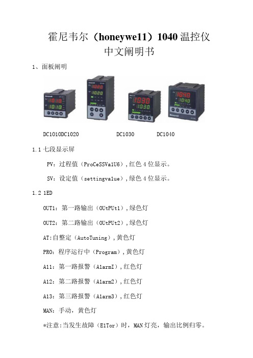
霍尼韦尔(honeywe11)1040温控仪中文阐明书1、面板阐明DC1O1ODC1020 DC1030 DC10401.1七段显示屏PV:过程值(ProCeSSVa1U6),红色4位显示。
SV:设定值(settingva1ue),绿色4位显示。
1.21EDOUT1:第一路输出(OUtPUt1),绿色灯OUT2:第二路输出(OUtPUt2),绿色灯AT:自整定(AutoTuning),黄色灯PRO:程序运行中(Program),黄色灯A11:第一路报警(A1armI),红色灯A12:第二路报警(A1arm2),红色灯A13:第三路报警(A1arm3),红色灯MAN:手动,黄色灯*注意:当发生故障(E1Tor)时,MAN灯亮,输出比例归零。
1.3按键SET:设定键(写入设定值或切换模式)<:移位键(移动设定位数)XZ:减少键△:增长键A/M:自动(AUtO)/手动(ManUa1)切换键2、自整定功能(AutoTuning)2.1将AT(在USer1eVe中)设定为YES,启动自整定功能2.2ATV1:自整定偏移量(AUTOTuningoffsetVaiue)SV减ATV1为自整定设定点,设定ATV1可以防止自整定期,因PV值振荡而超过设定点(OVerShoOt).3、故障信息注意:当有标识的故障发生时,请与供应商联络。
4、操作流程按“SET”键持续5秒当1CK='1111'时,按“SET"键和'<'键持续5秒。
当1CK='0000'时,按“SET"键和'<]'键持续5秒。
1.11eve11⑵ ⑶ ⑴:按“SET”键。
(2):(3): (4):4.1.1按移位键(V)变化参数。
按下移位键,第一位数开始闪烁。
按增长键()或公少键()对立数值作增长或减少,再按移位键到第二位数,当所有数值设定好后,按SET键完毕数值设定。
- 1、下载文档前请自行甄别文档内容的完整性,平台不提供额外的编辑、内容补充、找答案等附加服务。
- 2、"仅部分预览"的文档,不可在线预览部分如存在完整性等问题,可反馈申请退款(可完整预览的文档不适用该条件!)。
- 3、如文档侵犯您的权益,请联系客服反馈,我们会尽快为您处理(人工客服工作时间:9:00-18:30)。
0.1Ω 10μV
±0.1 ±0.1 ±0.1 ±0.1 ±0.1 ±0.1 ±0.1 ±0.1 ±0.1 ±0.1 ±0.1 ±0.1 ±0.1 ±0.1 ±0.1 ±0.1
-200 至 +850 -328 至 +1562 -60 至 +250 -76 至 +482 +400 至 +1820 +752 至 +3308 -100 至 +1000 -148 至 +1832 -100 至 +1200 -148 至 +2192 -180 至 +1372 -192 至 +2502 -100 至 +900 -148 至 +1652 -180 至 +1300 -292 至 +2372 -50 至 +1760 -58 至 +3200 -50 至 +1760 -58 至 +3200 -200 至 +400 -328 至 +752 -200 至 +600 -328 至 +1112 0 至 +2300 +32 至 +4172 0 至 +2300 +32 至 +4172
TC, difference
TC, difference
RTD, difference or average
or average
Resistance, 4-wire or average with internal CJC with external CJC
mV, difference or average
STT171特性
• 模拟量4-20 mA 输出 • 热电阻或电阻值输入 • B型 DIN 导轨或头部安装 • 传感器故障信号符合 NAMUR NE43 规定 • 使用 STT17C 组态工具和 PC 电脑对其进行组态
STT173特性
• 模拟量4-20 mA 输出 • 热电阻、热电偶、电阻值或毫伏输入 • B型 DIN 导轨或头部安装 • 传感器故障信号符合 NAMUR NE43 规定 • 使用 STT17C 组态工具和 PC 电脑对其进行组态 • 电流隔离
STT17H特性
• HART/4-20 mA 输出 • 热电阻、热电偶、电阻值或毫伏输入 • 单传感器或双传感器(差值或平均值)输入 • B型 DIN 导轨或头部安装 • 可以接 HART 多点方式连接 • 传感器故障信号符合 NAMUR NE43 规定 • 使用 STT17C 组态工具和 PC 电脑或 HART 现场组
警告:STT17C 不可用于危险场所
系统要求:
Windows 98SE,ME,2000 及 XP 并满足以下配置:
内存
16MB
显示分辨率
800×600
硬盘空间
12MB
1 2
STT1红 黑
*黄 *绿
接头
接收设备 + 输入
* 仅在线组态时连接
USB 电缆
4
STT3000/170 系列智能温度变送器
Bus termination
输出:
Bus connection
FOUNDATION
Segment coupler
Bus termination
Bus connection
PA
Segment coupler
3
STT3000/170 系列智能温度变送器
STT17C组态工具
STT17C 可组态 STT173 和 STT17H。将组态软件装入电脑后,操作员无需培训,即可通过直观的图形用户接口进 行组态。STT17C 包括所有软件和用于组态 STT171、STT173 和 STT17H 变送器所需的接口硬件。
电气输入特性
电源 ...................................... 8 至 30 VDC 电源电压影响 ...................... ≤0.005%量程 / VDC 预热时间 .............................. 5 分钟 响应时间(可编程)........... 0.33 至 60 秒
电流输出特性
信号输出范围 ...................... 4 至 20 mA 刷新时间 .............................. 135 毫秒 回路电阻 .............................. ≤(供电电压 - 8)/ 0.023 A
0 至 870Ω
接线(续)
STT17H
RTD, 2-wire
输入:
RTD, 3-wire
RTD, 4-wire
TC, internal CJC
STT17F/STT17P
输入:
RTD, 2-wire
RTD, 3-wire
RTD, 4-wire
2X RTD, 2-wire
TC, external CJC
mV
Resistance, 2-wire Resistance, 3-wire
输出: 2-wire installation
2X RTD, 2- / 3-wire
Resistance, 2-wire Resistance, 3-wire Resistance, 4-wire
2X resistance, 2- / 3-wire
TC, internal CJC
TC, 2-wire external CJC
1
尺寸(所有型号)
STT3000/170 系列智能温度变送器
d 6 mm
33 mm D44 mm
20.2 mm
接线
STT171
RTD, 2-wire
输入:
RTD, 3-wire Resistance, 2-wire Resistance, 3-wire
STT173
RTD, 2-wire
输入:
RTD, 3-wire
报警
可编程 .................................. 3.5 至 4 mA 下限 20 至 23 mA 上限
NAMUR NE43 上限 ............. 23 mA NAMUR NE43 下限.............. 3.5 mA
认证证书
认证机构:
标准:
EMC 2004/108/EC
CSA,CAN / CSA ................. C22.2 No. 157,E60079-11,
UL 913
Ex / I.S. 认证: KEMA 06 ATEX 0042 X ....... II 1 GD,T80℃...105℃
EEx ia IIC T4...T6 T4 最高环境温度 ................. 85℃ T6 最高环境温度 ................. 60℃ 应用区域............................... 0,1,2,20,21 or 22 FM,应用于......................... IS,CL I,DIV 1,Grp. A-D,T4...T6
5
STT3000/170 系列智能温度变送器
STT173-BS性能指示
传感器 类型
基本精度*
固定
量程
额定范围
℃
°F
标准
环境温度每变化1℃
最小量程** (1.8°F)的温度影响***
固定
量程
Pt100 Ni100
B E J K L N R S T U W3 W5 Ω mV
0.5℃(0.9°F) 0.5℃(0.9°F) 2℃(3.6°F) 1℃(1.8°F) 1℃(1.8°F) 1℃(1.8°F) 1℃(1.8°F) 1℃(1.8°F) 2℃(3.6°F) 2℃(3.6°F) 1℃(1.8°F) 1℃(1.8°F) 2℃(3.6°F) 2℃(3.6°F)
Ex / I.S. 数据: Ui(max) ........................... 30 VDC Ii(max) ............................. 120 mADC Pi(max) ............................ 0.84 W Li(max) ............................ 10μH Ci(max) ............................ 1.0 nF
态器对其进行组态
• 电流隔离
STT17F和STT17P特性
• 基金会现场总线(FF)或 PROFIBUS PA 方式 • 热电阻、热电偶、电阻值或毫伏输入 • 单传感器或双传感器(差值、平均值或容余)输入 • B型 DIN 导轨或头部安装 • 功能块:2 个模拟量,1个 PID • FISCO认证 • 基本或链路活动调度器 • 电流隔离
STT171-BS性能指示
传感器 类型
Pt100 Ni100
Ω
基本精度*
固定
0.5℃(0.9°F) 0.5℃(0.9°F)
0.2Ω
量程
±0.1 ±0.1 ±0.1
额定范围
℃
°F
-200 至 850 -328 至 1562
