光伏逆变器中英文对照资料外文翻译文献
关于逆变的中外文资料

Inverters1.1 Autonomous OperationWhile electrical power generation changes due to different irradiance levels,the energy still has to be stored, especially when the time of demand is different from the time of generation - which is very often the case.Therefore storage consisting of a battery and an adequate charge/discharge controller has to be added to the system (see Figure 1.1). Often alternating voltage is needed, and thus an inverter has to be implemented in order to convert DC from the PV panel and storage to the AC required.Fig. 1.1.Block diagram of an autonomous PV system with storage and an inverter for AC loads.The most simple way to achieve this is by switching the polarity of the DC with the frequency needed for AC (50 Hz or 60 Hz), using devices called rectangular inverters. Yet his kind of AC conversion leads to high distortion levels with higher frequency artifacts, which could damage sensitive loads and interfere with radio signals.A better approximation of the sine-form requested is to use switches with some zero voltage period (so called trapezoid inverters). Distortion levels for this type of inverter are lower than for the rectangular inverters, but still high.Formerly so called “rotating inverters” have been used. At those, a DC motor is coupled to an AC generator. This method enables a very smooth sinusoidal output, but efficiency is relatively poor and the frequency varies when a change of the loadoccurs.State-of-the-art technology at inverters is PWM (pulse width modulation).Here DC is switched on and off for a short period of time (a pulse) in such a manner that the integral of the pulse is equivalent to the actual level at the sinus profile required. The next pulse width is also adapted in that way so the integral is equivalent to the next actual level of the sinus given by the controller. After filtering the output of such an inverter is very close to a perfect sinus at relatively high efficiency (up to 96%). 1.2 Inverters for Electrical Grid InjectionIn autonomous PV systems the energy yield varies due to daily and seasonal changes of solar irradiance. In Central Europe the average irradiance received during summer is about five to six times higher than in winter.Therefore those PV systems have to be equipped with enough energy storage devices to supply loads during periods of poor or no radiation. Storage makes a system more expensive (especially seasonal storage) and increases the costs of generated energy. Therefore, the public grid is used as “storage”or buffer into which energy is fed during periods of overproduction and likewise, taken during periods lacking photovoltaic power generation . To facilitate grid injection, DC power from the PV generator has to be converted into AC according to the requirements of the public grid.Counter to inverters of autonomous systems, the reference sinus for the PWM is not given by the controller but by the grid. While the impedance of the grid is generally very low, the inverters still have to be synchronized before operation and adapt to the particular voltage and frequency of any given grid. Therefore, inverters used for grid connections are different from the ones used for autonomous systems. In case of any connection to the grid,utilities set standards in order to maintain distortion levels and synchronization of voltage and current within certain limits. In the past numerous failures had been reported which involved grid connected inverters, the technology nowadays has been found to be very stable. Only a few types of inverters are capable of working in both operation modes: gridconnected and autonomous.While small loads can often be used for DC, general appliances require AC of 115 V or 230 V with 50 Hz or 60 Hz. For power requirements higher than 3-10 kW a three-phase AC system is usually preferred.Fig. 1.2. Scheme of a typical single-phase PV grid injection system equipped with a Maximum-Power-Point-Tracker (MPPT) and an energy counter (kWh).Many different types of PV grid injectors are available. They differ by their way of commutation whether they feature galvanic separation from the grid(e.g., by transformers), and by the type of power electronics they are using (thyristor, GTO, bipolar-transistor, MOS-FET or IGBT). Due to adequate funding programs for PV power plants of these dimensions (e.g., the German 1,000 and 100,000 PV Roofs Program), most of these grid injectors are available in a power range of 0.6 to 5 kW.A widely utilized principle is the pulse-width-modulation (PWM). For PWM to achieve a 50 or 60 Hz sinus for an AC grid, the first step is to get a rectangular current by shifting the polarity (each 10 ms for 50 Hz, or each 8.33 ms for 60 Hz) of the DC output from the PV power station. The rectangular current is then switched on and off (“pulsed”) in such a manner that the resulting integral of the pulses is as close as possible to the equivalent sinus value to be achieved (see Figure 3. 3). The pulsing is carried out at a relatively high frequency (10 to 100 kHz), the consequent integra tion is done by “smoothing” the pulses via a lowpass filter.The frequency and phase have to be adjusted to the actual grid condition and if the “guiding” grid fails the inverter also has to be switched off immediately. In general, a grid inverter should fulfill the following requirements:(1)The output current follows the grid voltage synchronously (“currentsource”).(2)The distortion and consequent spectral harmonics of the grid frequency are not allowed to surpass given thresholds by the norms (e.g., VDE 0838,EN 60555), which requires a good adaption of the output current to the sinus form.(3)The injected current and the grid voltage should have no phase difference (cos p= 1) in order to avoid the bouncing of reactive power between grid and inverter whichwould cause additional losses and eventually overcharge.(4)In failure condition (missing grid voltage, strong frequency shifts, short circuits or isolation failures) the grid injector has to be disconnected from the grid automatically.(5)Control signals in the grid, often used by the energy suppliers, should not be disturbed by the grid injector nor should they impact his operation.(6)The input terminal resistance should be well adapted to the actual properties of the solar generator during operation, e.g., by “Maximum Power Point Tracking“ (MPPT).(7)Fluctuations of the input voltage (e.g., at 100 Hz caused for a single phase injector device) should be low (< 3%) to allow operation of the solar generator close to its Maximum-Power-Point.(8)Overvoltage, e.g., caused by a solar generator operating at low temperatures near open circuit conditions, should not lead to defects.(9)For overload conditions the input power is limited to a defined value by shifting the point of operation of the PV generator toward open circuit voltage. This could happen when the nominal power of the inverter is lower than the nominal power from the PV generator. Such an occurrence infrequently (see Figure 7.27) leads, at very high irradiance, to an input overload of the grid injector.(10)The grid inverter should be supplied by the solar generator to avoid consumption from the grid (e.g., at nighttime). The inverter should go into operation mode already at low irradiance levels and should operate in a stable manner. Modern PV systems are already injecting to the grid at irradiance levels of 50 W/m2 and efficiencies of 90% can be achieved at 10% of the nominal inverter power so far.(11)Input and output terminals should be protected against transient overvoltages (“surge”, e.g., ca used by lightning strokes). This is mainly carried out by the application of overvoltage or surge arrester devices.(12)The regulations for “electromagnetic compatibility” (EMC), e.g., EN 55014, have to be adhering.(13) Noise emission of the devices should be low, so as to allow operation also in inhabited buildings.The quality of power entering the utility-grid from a PV system is also of concern to the utilities. If too many harmonics are present in the inverter output they may cause interference in loads at other locations (that may require sinusoidal power) or at utility equipment (e.g., for data transmission over the transmission line). Electrical machinery (e.g., motors) operating with a lot of harmonic distortions in the power supply are heating up and the lifetimes of the bearings are reduced due to vibrations.IEEE 519 is specific to grid-connected PV systems and also gives standards relating to:Voltage disturbances: Voltage at inverter output should not be more than 5% higher than the voltage at the point of utility connection and thus the inverter should sense grid voltage abnormalities and disconnect the inverter when indicated. Disconnection should occur within 10 cycles if the utility voltage either drops below 50% of its nominal value or increases above 110% of its nominal value. If the utility line voltage is between 50% and 92% of its nominal value, the inverter should shut down within two seconds.Frequency d isturbances: If, at 60 Hz systems, the line frequency falls below 59.5 Hz or goes above 60.5 Hz, the inverter should be disconnected.Power factors: The power factor (caused by a phase shift between current and voltage) should not be lower than 0.85.Injection of DC in to the AC grid : DC current must be no greater than 0.5% of rated inverter output current.Also, regulations on islanding protection, reconnecting after grid failure and restoration, grounding surge protection, DC and AC disconnecting are assumed in that norm. Sometimes additional requirements of the local energy utilities have to be taken into account. A collection of further international and European regulations are given in the Annex.A typical configuration of a single phase PV injection system is shown in Figure3.2 (with a maximum-power-point-tracker and an energy counter).1.3 Types of inverters1.3.1 External Commutated InvertersExternal commutated inverters need an external AC voltage supply which is not part of the inverter), to supply the “commutation-voltage” during the commutation period (e.g., for thyristors, see also DIN 41750 part 2). At grid controlled inverters this AC voltage is supplied by the grid. External controlled inverters are operated via “natural commutation.” A main feature of them is that a “current rectifier valve” with an actual higher voltage potential after ignition takes over the current from a current rectifier valve in front of it (Heumann 1996).The external commutated, grid-controlled inverter is commonly used for high power applications. For low power applications (<1 MW), which are most common for PV power supply systems, self-commuted inverters are the state-of-the-art.1.3.2 Self Commutated InvertersSelf-commutated inverters do not need an external AC-voltage supply for commutation (see DIN 41 750, part 5). The commutation voltage is supplied either by an energy storage which is part of the inverter (commonly by a “delete”-capacity) or by increase of resistance of the current rectifier valve to be switched off (e.g., a MOS-FET power transistor or an IGBT). Self commutated inverters have been designed for all kind of conversion of electrical energy for energy flows in one or both directions. In the power range relevant for PV-applications (< 1 MW) nowadays exclusively selfcommutated inverters are used.1.3.3 Inverters Based on PWMA self-commuted inverter, which has an output voltage (resp. current) that is controlled by pulses is called pulse-inverter. At this type of inverter the number of commutations per period is increased by frequent on- and off switching at the pulse-frequency f within this period, which may be used to reduce harmonics of current and voltage, because it is equivalent to an increment of pulse numbers. At grid-controlled inverters the increment of pulse numbers is only possible via an adequate augmentation of inverter rectification braces. Figure 3.3 shows the coupling of a DC voltage source (PV-generator) with an AC voltage source via a pulse inverter in a single phase bridge circuit.Fig. 1.3. Scheme of circuit of a single phase sinus inverter based on pulse width modulation forphotovoltaic grid injection.The harmonics of the current are defined by the inductances of the AC side.So,in order to fulfill the directives of the utilities for grid-feeding (EN 60 555), a certain minimum inductance should be kept.The inverter shown in Fig. 3.3 supplementary is equipped with a low pass filter and an isolation transformer, so all harmonics up to the order of n-1 are eliminated, while n represents the number of pulses during each period of the AC current. For elevated switching frequencies the switching losses in the power electronic devices are increased. At low switching frequencies the expenses for the low pass filter increases. While for the sinusoidal current the power into the single-phase grid pulses with twice the frequency, the DC from the PV-generator is superimposed by a sinusoidal current with twice the grid frequency.中文译文逆变1.1自主运作虽然发电的变化,由于不同的辐射水平,能源仍然需要储存,特别是当时间需求不在同一时间时,这是非常常见的情况。
逆变器中英文对照外文翻译文献

中英文对照外文翻译文献(文档含英文原文和中文翻译)逆变器1引言逆变器是一种电动装置,转换成直流电(DC),交流电流转换的AC(交流)可以在任何所需的电压和频率使用适当的变压器,开关,控制circuits.Solid状态逆变器有没有移动部件,用于广泛的应用范围从小型计算机开关电源,高压大型电力公司电力,运输散装直接电流应用。
逆变器通常用于提供交流电源,直流电源,如太阳能电池板或电池。
逆变器的主要有两种类型。
修改后的正弦波逆变器的输出是类似方波输出,输出变为零伏前一段时间切换积极或消极的除外。
它是简单,成本低,是大多数电子设备兼容,除敏感或专用设备,例如某些激光打印机。
一个纯正弦波逆变器产生一个近乎完美的正弦波输出(<3%的总谐波失真),本质上是相同的公用事业提供电网。
因此,它是与所有的交流电的电子设备兼容。
这是在电网领带逆变器使用的类型。
它的设计更复杂,成本5或10倍以上每单位功率电逆变器是一个高功率的电子振荡器。
它这样命名,因为早期的机械AC到DC转换器工作在反向,因而被“倒”,将直流电转换AC.The变频器执行的整流器对面功能。
2应用2.1直流电源利用率逆变器从交流电力来源,如电池,太阳能电池板,燃料电池的直流电转换成。
电力,可以在任何所需的电压,特别是它可以操作交流电源操作而设计的设备,或纠正,以产生任何所需的voltage Grid领带逆变器的直流送入分销网络的能量,因为它们产生电流交替使用相同的波形和频率分配制度提供。
他们还可以关掉一个blackout.Micro逆变器的情况下自动转换成交流电电网的电流直接从当前个别太阳能电池板。
默认情况下,他们是格领带设计。
2.2不间断电源不间断电源(UPS),电池和逆变器,交流电源,主电源不可用时使用。
当主电源恢复正常时,整流提供直流电源给电池充电。
2.3感应加热逆变器的低频交流主电源转换到更高频率的感应加热使用。
要做到这一点,首先纠正交流电源提供直流电源。
太阳能电池中英文对照外文翻译文献

中英文翻译英文原文Historical Review of Solar EnergySolar generally refers to the suns radiation energy. Carried out in the solar interior from H together into a helium the nuclear reaction, kept a huge release of energy, and continue to the space radiation energy, which is solar energy. This solar nuclear fusion reaction inside the can to maintain the hundreds of millions of first time. Solar radiation to space launch 3.8x10 ^ 23kW power of the radiation, of which 20 billionth of the Earths atmosphere to reach. Solar energy reaching the Earths atmosphere, 30% of the atmosphere reflectance, 23% of atmospheric absorption, and the rest to reach the Earths surface.Its power of 80 trillion kW, that is to say a second exposure to the suns energy on Earth is equivalent to five million tons of coal combustion heat release. The average per square meter in the atmosphere outside the area of energy per minute to receive about 1367w. A broad sense of the solar energy on earth many sources, such as wind energy, chemical energy, potential energy of water and so on. The narrow sense is limited to solar radiation of solar light thermal, photovoltaic and photochemical conversion of the directly.At this stage, the worlds solar energy is still the focus of the study of solar energy power plant, but the diversification of the use of the condenser, and the introduction of flat-plate collector and a low boiling point working fluid, the device gradually expanded up to maximum output power 73.64kW, Objective To compare the clear and practical, cost remains high. The construction of a typical device are as follows: 1901, California built a solar-powered pumping devices, the use of truncated cone condenser power: 7.36kW; 1902 ~ 1908 years, built in the United States five sets of double-cycle solar-powered engines, the use of flat-panel collector and a low boiling point working fluid; in 1913,Human use of solar energy has a long history. China more than 2000 years ago,back in the Warring States period, one will find that the use of four steel mirror to focus sunlight ignition; use of solar energy to dry agricultural products. The development of modern, solar energy has become increasingly widespread use, it includes the use of solar energy solar thermal, solar photovoltaic and solar energy us e, such as the photochemical use. The use of solar photochemical reaction, a passive use (photo-thermal conversion) and the photoelectric conversion in two ways. A new solar power and renewable sources of energy use.Silicon photovoltaic cells mainly in the absorption of solar light energy emitted by silicon photocell is mainly extracted from the sand by the development of Bell Labs. Solar energy is the internal or the surface of the sun sunspot continuous process of nuclear fusion reactions produce energy. Earths orbit on the average solar radiation intensity for the 1367w / ㎡. Circumference of the Earths equator to 40000km, and thus calculated the Earths energy can be obtained 173000TW. At sea level standard for peak intensity 1kw/m2, a point on the Earths surface 24h of the annual average radiation intensity 0.20kw / ㎡, which is equivalent to have 102000TW energy Human dependence on these energy to survive, including all other forms of renewable energy (except for geothermal energy resources), although the total amount of solar energy resources is the human equivalent of the energy used by ten thousand times, but low energy density of solar energy, and it vary from place to place, from time to time change, the development and utilization of solar energy which is facing a major problem. These features will make solar energy in the integrated energy system of the role of subject to certain restrictions.The use of solar cells, through the photoelectric conversion to solar energy conversion is included in electricity, the use of solar water heaters, the use of solar heat hot water and use water for power generation, using solar energy for desalination. Now, the use of solar energy is not very popular, the use of solar power costs are high there, the problem of low conversion efficiency, but for satellite solar cells to provide energy has been applied.Although the Earths atmosphere solar radiation to the total energy only 22 billionths of a radiation energy, it has been as high as 173,000 TW, that is to say a second exposure to the suns energy on Earth is equivalent to five million tons of coal. Earth wind energy, hydropower, ocean thermal energy, wave energy and tidal energy as well as some comes from the sun; even in the face of the earths fossil fuels (such as coal, oil, natural gas, etc.) that is fundamentally Since ancient times the storage of solar energy down, so by including a broad range of solar energy is very large,he narrow sense is limited to solar radiation of solar light thermal, photovoltaic and photochemical conversion of the directly.Solar energy is the first time, but also renewable energy. It is rich in resources, can use free of charge, and without transportation, without any pollution to the environment. For mankind to create a new life, so that social and human energy into a era of reducing pollution.Solar cells have to respond to a light and convert solar energy to power the device. Photovoltaic effect can produce many kinds of materials, such as: single crystal silicon, polycrystalline silicon, amorphous silicon, gallium arsenide, copper indium selenium. They are basically the same principle of power generation is now crystal as an example to describe the process of light generation. P-type crystalline silicon available after phosphorus-doped N-type silicon, the formation of P-N junction.When the surface of solar light, the silicon material to be part of photon absorption; photon energy transfer to the silicon atom, electronic transitions have taken place, as a free-electron concentration in the PN junction formed on both sides of the potential difference, when the external circuit connected when the effects of the voltage, there will be a current flowing through the external circuit have a certain amount of output power. The substance of this process are: photon energy into electrical energy conversion process.Si is our planets abundance of storage materials. Since the 19th century, scientists discovered the properties of crystalline silicon semiconductor, it almost changed everything, even human thought, end of the 20th century. Our lives can be seen everywhere, silicon figure and role of crystalline silicon solar cells is the formation of the past 15 years the fastest growing industry. Production process can be divided into five steps: a, purification process b, the process of pulling rod c, slicing the process of d, the process of system battery e, the course package.Solar photovoltaicIs a component of photovoltaic panels in the sun exposure will generate direct current power generation devices, from virtually all semiconductor materials (eg silicon) are made of thin photovoltaic cells composed of solid. Because there is no part of activity, and would thus be a long time operation would not lead to any loss. Simple photovoltaic cells for watches and computers to provide energy, and more complex PV systems to provide lighting for the housing and power supply. Photovoltaic panels can be made into components of different shapes, and componentscan be connected to generate more power. In recent years, the surface of the roof and building will be the use of photovoltaic panels components,Even be used as windows, skylights or sheltered part of devices, which are often called photovoltaic facilities with PV systems in buildings.Solar thermalModern technology solar thermal polymerization sunlight and use its energy produced hot water, steam and electricity. In addition to the use of appropriate technology to collect solar energy, the building can also make use of the suns light and heat energy is added in the design of appropriate equipment, such as large windows or use of the south can absorb and slowly release the sun heat the building materials .According to records, human use of solar energy has more than 3,000 years of history. To solar energy as an energy and power use, only 300 years of history. The real solar as the near future to add much-needed energy, the basis of the future energy mix is the latest thing. Since the 20th century, 70s, solar technology has made rapid advances, solar energy use with each passing day. Solar energy utilization in modern history from the French engineers in 1615 in the Solomon and Germany Cox invented the worlds first solar-powered engines run. The invention is a use of solar energy heating the air to the expansion and pumping machines acting.In 1615 ~ 1900, between the developed world and more than one solar power plant and a number of other solar energy devices. Almost all of these power plants collect the sun means the use of condenser, engine power is not, the working fluid is water vapor, which is very expensive, not practical value, the majority of individual studies for manufacturing solar enthusiasts. 100 years of the 20th century, the history of the development of solar energy technology in general can be divided into seven stages.1. The First Stage (1900---1920)In this stage, the research focus of solar energy in the world were still on the solar-powered device which variable photospot method were applied and flat plate heat collector and low boiling point actuating medium were started to use; the capacity of the device was gradually expanded with the max. output power of 73.46kW; device was utilized with the definite end-use and in higher cost.The typical built device included: one set of solar energy pumping device constructed in California of U.S in 1901 which employed truncation taper photospot with the power of 7.36kW; 5 sets of twin-circulated solar-powered engine built in U.Sin 1902 to 1908 which employed the flat plate heat collector and low boiling point actuating medium; 1 set of solar energy pump comprised of 5 parabolic mirror in a length of 62.5m, width of 4m built in Cairo of Egypt in which the total light collecting area could reach 1250m2.2. The Second Stage (1920-1965)For these 20 years, the research of solar energy was implementing on the poor stage, which the mandate to participate in the development and the research projects had been widely declined due to the mass utilization of fossil fuels and the second world war (1935---1945) while the solar energy couldn’t satisf y the urgent demand upon the energy. Therefore, the research and development of solar energy was due to be gradually deserted.3. The Third Stage (1945-1965)For these 20 years after the Second World War, some foresight person has noticed that the petroleum and natural gas resources had been rapidly decreased and called for attention on these issues in order to gradually promote the recovery and development of the solar energy research. Solar energy institutes were setup and academic exchanges and exhibitions were held which raised the research upsurge again on solar energy.In this period, great progress was achieved in the research of solar energy, in particular: the foundation theory of selective paints proposed in the First International Solar Thermal Academic Conference in 1955, which black nickel had been developed as the practical selective paints, contributing to development of high-effective heat collector; the practical silicon solar cells developed by Bell Lab in U.S in 1954 which laid the foundation for large scale utilization of photovoltaic generation.Furthermore, there were still other significant results, including:a. One set of 50kW solar stove was built by French National Research Center in 1952;b. The worldwide prototype ammonia-water absorbing air conditioning system heated by flat plate heat collector with the capacity of 5 tons was built in Flor ida of U.S in 1960;c. An engine equipped with silicon window was invented in 1961.In this stage, research on foundation theory and foundation material of solar energy was reinforced and academic breakthrough, i.e. selective paints and silicon solar cells were achieved. The flat plate had been well developed and ripe in technologies. Progress had been achieved in the research of solar energy absorbing airconditioners and a batch of pilot solar room was established. Preliminary research was conducted on the engine and tower type solar-powered generation technologies.4. The Fourth Stage (1965---1973)In the stage, the research work on solar energy was standstill due to the reason that the utilization technologies of solar energy had entered into the growing stage which was no ripe in process, heavy in investment and lower in effect. Thus it cannot compete with conventional energy, which resulted in the absence of attention and support from the public, enterprise and government.5. The Fifth Stage (1973---1980)After petroleum played a leading role in the worldwide energy structure, it has been a key factor to control the economic and determine the fatal, development and declining of a country. After the explosion of Middle East War at Oc., 1973, OPEC employed the method of declining the production and increasing the price to support the struggle and safeguard the national benefits which resulted in heavy economic attack for those countries that relied on importing large amount of inexpensive petroleum from the region of Middle East. Thus, some people in the western countries were frightened to call that the energy or petroleum crisis had been launched in the world. This crisis made people realized that the existing energy structure should be completely changed and transition to the future energy structure should be speed up.From that on, many countries, especially the industrialized countries turned their attention towards the support on the research and development of solar energy and other renewable energy technologies. The upsurge of developing and utilizing solar energy had been raised again in the world. In 1973, U.S drew up a government scale sunlight power generation program which the research budget for solar energy were increased in a large amount, and solar energy development bank was to established to facilitate the solar energy products to be commercialized. In 1974, Japan published the sunlight program made by the government, among which the solar energy development projects included solar room, industrial-use solar energy system, solar thermal generation, solar cells production system, scattered and large scale photovoltaic generation system. In order to implement this program, the government of Japan input large amount of manpower, material resources and financial resources.The upsurge on the utilization of solar energy raised in 1970s in the world also impacted on China. Some foresight technicians started to devote to the solar energy industry one after another and positively proposed to the relative department of the government and published books and periodicals to introduce the international trendson the utilization of solar energy. Solar stove was popularized and utilized in countryside; solar water heater was launched in the city; solar cells used in space have started to be applied in the ground. In 1975, the first national solar energy utilization working exchanges conference held in An yang, Henan Province further promoted the development of solar energy industry in China. After this meeting, the solar energy research and promotion had been brought into the government program and awarded support of specialized fund and material. In some universities and institutes, solar energy task team and research departments were established one after another. Solar energy research institutes were also launched in some places. At that time, an upsurge on utilization of solar energy was emerging in China.During this period, research and development of solar energy entered into an unprecedented well-developed stage with the following characteristics:a. Each country enhanced planning on solar energy research. Many countries worked out short term and long-term sunlight program. The utilization of solar energy had been a governmental action with intensive support. The international cooperation was very active which some developing countries had started to participate in the utilization of solar energy.b. The research field was expanding; research work was developed day by day and significant results achieved, for example, CPC, vacuum heat collecting pipe, non-crystal silicon solar cells, water-photolyzed hydrogen production and solar energy thermal power generation.c. The solar energy development program worked out by each country existed the problems that the requirement was too high and urgent and insufficient expectation on difficulty in implementation. They have thought to replace the mineral energy in th e short time and to utilize the solar energy in large scale. For example, U.S has once scheduled to build a small size solar energy demonstration satellite power station in 1985 and one set of 5 million kW space solar energy power station in 1995. In fact, this program has been adjusted in later, and the space solar energy power station has not yet been realized.d. Products such as solar water heater and solar cells were started to commercialize. The solar energy sector has been preliminarily established with a small scale and ineffective economic effects.6. The Sixth Stage (1980-1992)The upsurge on utilization of solar energy emerged in 1970s was fallen into a stage of being developed in a low and slow step in 1980s. Many countries in the worlddeclined the research budget for solar energy in successive in a large amount, in particular the U.S.The main reasons resulted in this situation were that the internati onal oil price was corrected in a large range while solar energy product cost was still remaining as before which may be of no competitive capability; no any significant breakthrough on solar energy technologies to increase the efficiency and reduce the cost which led to break down people’s confidence to develop solar energy; increased development on nuclear power which may restrain on a certain degree on the development of solar energy.Influenced on the turndown of solar energy in the worldwide in 1980s, research work in China also declined in a certain degree. Due to the reason that the utilization of solar energy was heavy in investment, ineffective in results, difficult in energy storage and large in land covering, solar energy should be considered as t he future energy. Some person even proposed that the technology could be introduced after it would be developed successfully. Only few people supported such viewpoint, but it was very harmful which will result in unfavorable influence on the development of solar energy industry.During this period, although the research budget has been mitigated in a large amount, the research work remained uninterruptedly, among which some projects achieved progress which facilitated people to investigate seriously on the program and goads worked out before and to adjust the research focus so that to strive for great achievement by less input.7. The Seventh Stage (1992---Until Now)Excessive burning of fossil fuel led to worldwide environmental pollution and ecological destruction, which has been threatened the substance and development of human beings. Under such circumstance, UN held the international environment and development conference in Brazil in 1992. On this meeting, a series of important document were published including the Environment and Development Manifesto,Agenda of 21st century and UN Framework Pact on Climate Changing in which the environment and development were brought into the integrated framework, and sustainable model was established. After this conference, each country enhanced the development of clean energy technologies, and developed the solar energy in line with the environmental protection so as to make the utilization of solar energy be well developed.After this conference, Chinese government also turned their attention towards theenvironment and development and pointed out 10 pieces of tactic and measure definitely to develop and popularize the clean energy including solar energy, wind energy, thermal energy, tidal energy and biomass energy in accordance with the reality; worked out Agenda of 21st century in China and further focused the solar energy projects. In 1995, the State Planning, the State Economic and Trade Commission, the State Ministry of Science and Technology worked out the Outline for Development of New and Renewable Energy from 1996 to 2010, which definitely pointed out the goads, objectives and relative tactic and measure towards the development of new and renewable energy from 1996 to 2010 in China. The publishing and implementation of the document further promoted the development of solar energy industry in China.In 1996, UN held the worldwide solar energy summit conference in Zimbabwe. The Solar Energy and Sustainable Development Manifesto was published after the meeting. Important document, i.e.Worldwide Solar Energy 10-Year Action and Program (1996---2005), International Solar Energy Pact, Worldwide Solar Energy Strategic Planning were discussed during the meeting. This meeting further showed each country’s commitment to d eveloping the solar energy. Worldwide joint action was required to extensively utilize the solar energy.After 1992, the worldwide utilization of solar energy has entered into a developing stage with the characteristic that:a. The utilization of solar energy can be consistent to the sustainable development and environment protection, and can be carried out jointly to realize the development strategy in the world;b. Definite development goals with focus projects and effective measure, which will be favorable to overcome the shortage to ensure the long-term development of solar energy industry;c. In the course of expanding the research of solar energy, attention was paid to convert the academic results into production, develop solar energy industry, speed u p the progress to be commercialized, expand the utilization field and scale and increase the economic benefits;d. Active international cooperation in the field of solar energy with expanding scale and obvious effect.In view of the review, the development of solar energy in the 20th century was not so smooth. Generally speaking, low tide period was happened after every high tide period. The low tide period lasted for nearly 45 years. The development of solar energy differed with that of coal, petroleum and nuclear energy in understanding anddevelopment period, which could be demonstrated that it was very difficulty to develop the solar energy and it cannot be realized to large scale utilize in the short term. On the other hand, it was showed that the utilization of solar energy was also affected by the supply of mineral energy, politics and war. However, in a word, the solar energy has achieved greatly in academic results in 20th century than in any other century.英文翻译太阳能利用史太阳能一般指太阳光的辐射能量。
光伏发电中英对照文献

外文参考文献译文及原文目录外文文献译文 (1)1.中国光伏发电的战略地位 (1)2.世界光伏产业现状和发展预测 (2)3.中国光伏发电市场和产业现状 (3)4.中国光复发电的市场预测和规划建议 (5)5.结论 (6)外文文献原文 (7)1.China's strategic position PV (7)2.The world's current situation and development of photovoltaic industryforecast (9)3.The Chinese PV market and industry statu s (10)4.China's PV market forecasting and planning proposals (13)5.Conclusions (15)外文文献译文1、中国光伏发电的战略地位1.1 中国的能源资源和可再生能源现状和预测;无论从世界还是从中国来看,常规能源都是很有限的,中国的一次能源储量远远低于世界的平均水平,大约只有世界总储量的10%。
从长远来看,可再生能源将是未来人类的主要能源来源,因此世界上多数发达国家和部分发展中国家都十分重视可再生能源对未来能源供应的重要作用。
在新的可再生能源中,光伏发电和风力发电是发展最快的,世界各国都把太阳能光伏发电的商业化开发和利用作为重要的发展方向。
根据欧洲JRC 的预测,到2030年太阳能发电将在世界电力的供应中显现其重要作用,达到10%以上,可再生能源在总能源结构中占到30%;2050 年太阳能发电将占总能耗的20%,可再生能源占到50%以上,到本世纪末太阳能发电将在能源结构中起到主导作用。
我国政府重视可再生能源技术的发展,主要有水能、风能、生物质能、太阳能、地热能和海洋能等。
我国目前可再生能源的发展现状如下:水能:我国经济可开发的水能资源量为3.9 亿千瓦,年发电量1.7 万亿千瓦时,其中5 万千瓦及以下的小水电资源量为1.25 亿千瓦。
光伏发电逆变器毕业论文中英文资料外文翻译文献
光伏发电逆变器毕业论文中英文资料外文翻译文献附录:文献翻译TMS320LF2407, TMS320LF2406, TMS320LF2402TMS320LC2406, TMS320LC2404, MS320LC2402DSP CONTROLLERSThe TMS320LF240x and TMS320LC240x devices, new members of the ‘24x family of digital signal processor (DSP) controllers, are part of the C2000 platform of fixed-point DSPs. The ‘240x devices offer the enhanced TMS320 architectural design of the ‘C2xx core CPU for low-cost, low-power, high-performance processing capabilities. Several advanced peripherals, optimized for digital motor and motion control applications, have been integrated to provide a true single chip DSP controller. While code-compatible with the existing ‘24x DSP controller devices, the ‘240x offers increased processing performance (30 MIPS) and a higher level of peripheral integration. See the TMS320x240x device summary section for device-specific features.The ‘240x family offers an array of memory sizes and different peripherals tailored to meet the specific price/performance points required by various applications. Flash-based devices of up to 32K words offer a reprogrammable solution useful for:◆Applications requiring field programmability upgrades.◆Development and initial prototyping of applications that migrate to ROM-baseddevices.Flash devices and corresponding ROM devices are fully pin-to-pin compatible. Note that flash-based devices contain a 256-word boot ROM to facilitate in-circuit programming.All ‘240x devices offer at least one event manager module which has been optimized for digital motor control and power conversion applications. Capabilities of this module include centered- and/or edge-aligned PWM generation, programmable deadband to prevent shoot-through faults, and synchronized analog-to-digital conversion. Devices with dual event managers enable multiple motor and/or converter control with a single ‗240x DSP controller.The high performance, 10-bit analog-to-digital converter (ADC) has a minimum conversion time of 500 ns and offers up to 16 channels of analog input. The auto sequencing capability of the ADC allows a maximum of 16 conversions to take place in a single conversion session without any CPU overhead.A serial communications interface (SCI) is integrated on all devices to provide asynchronous communication to other devices in the system. For systems requiring additional communication interfaces; the ‘2407, ‘2406, and ‘2404 offer a 16-bit synchronous serial peripheral interface (SPI). The ‘2407 and ‘2406 offer a controller area network (CAN) communications module that meets 2.0B specifications. To maximize device flexibility, functional pins are also configurable as general purpose inputs/outputs (GPIO).To streamline development time, JTAG-compliant scan-based emulation has been integrated into all devices. This provides non-intrusive real-time capabilities required to debug digital control systems. A complete suite of code generation tools from C compilers to the industry-standard Code Composerdebugger supports this family. Numerous third party developers not only offer device-level development tools, but also system-level design and development support.PERIPHERALSThe integrated peripherals of the TMS320x240x are described in the following subsections:●Two event-manager modules (EV A, EVB)●Enhanced analog-to-digital converter (ADC) module●Controller area network (CAN) module●Serial communications interface (SCI) module●Serial peripheral interface (SPI) module●PLL-based clock module●Digital I/O and shared pin functions●External memory interfaces (‘LF2407 only)●Watchdog (WD) timer moduleEvent manager modules (EV A, EVB)The event-manager modules include general-purpose (GP) timers, full-compare/PWM units, capture units, and quadrature-encoder pulse (QEP) circuits. EV A‘s and EVB‘s timers, compare units, and capture units function identically. However, timer/unit names differ for EV A and EVB. Table 1 shows the module and signal names used. Table 1 shows the features and functionality available for the event-manager modules and highlights EV A nomenclature.Event managers A and B have identical peripheral register sets with EV A starting at 7400h and EVB starting at 7500h. The paragraphs in this section describe the function of GP timers, compare units, capture units, and QEPs using EV A nomenclature. These paragraphs are applicable to EVB with regard to function—however, module/signal names would differ.Table 1. Module and Signal Names for EV A and EVBEVENT MANAGER MODULESEV AMODULESIGNALEVBMODULESIGNALGP Timers Timer 1Timer 2T1PWM/T1CMPT2PWM/T2CMPTimer 3Timer 4T3PWM/T3CMPT4PWM/T4CMPCompare Units Compare 1Compare 2Compare 3PWM1/2PWM3/4PWM5/6Compare 4Compare 5Compare 6PWM7/8PWM9/10PWM11/12Capture Units Capture 1Capture 2Capture 3CAP1CAP2CAP3Capture 4Capture 5Capture 6CAP4CAP5CAP6QEP QEP1QEP2QEP1QEP2QEP3QEP4QEP3QEP4External Inputs DirectionExternalClockTDIRATCLKINADirectionExternal ClockTDIRBTCLKINBGeneral-purpose (GP) timersThere are two GP timers: The GP timer x (x = 1 or 2 for EV A; x = 3 or 4 for EVB) includes:● A 16-bit timer, up-/down-counter, TxCNT, for reads or writes● A 16-bit timer-compare register, TxCMPR (double-buffered with shadow register), forreads or writes● A 16-bit timer-period register, TxPR (double-buffered with shadow register), forreads or writes● A 16-bit timer-control register,TxCON, for reads or writes●Selectable internal or external input clocks● A programmable prescaler for internal or external clock inputs●Control and interrupt logic, for four maskable interrupts: underflow, overflow, timercompare, and period interrupts● A selectable direction input pin (TDIR) (to count up or down when directionalup-/down-count mode is selected)The GP timers can be operated independently or synchronized with each other. The compare register associated with each GP timer can be used for compare function and PWM-waveform generation. There are three continuous modes of operations for each GP timer in up- or up/down-counting operations. Internal or external input clocks with programmable prescaler are used for each GP timer. GP timers also provide the time base for the other event-manager submodules: GP timer 1 for all the compares and PWM circuits, GP timer 2/1 for the capture units and the quadrature-pulse counting operations. Double-buffering of the period and compare registers allows programmable change of the timer (PWM) period and the compare/PWM pulse width as needed.Full-compare unitsThere are three full-compare units on each event manager. These compare units use GP timer1 as the time base and generate six outputs for compare and PWM-waveform generation using programmable deadband circuit. The state of each of the six outputs is configured independently. The compare registers of the compare units are double-buffered, allowing programmable change of the compare/PWM pulse widths as needed.Programmable deadband generatorThe deadband generator circuit includes three 8-bit counters and an 8-bit compare register. Desired deadband values (from 0 to 24 µs) can be programmed into the compare register for the outputs of the three compare units. The deadband generation can be enabled/disabled for each compare unit output individually. The deadband-generator circuit produces two outputs (with orwithout deadband zone) for each compare unit output signal. The output states of the deadband generator are configurable and changeable as needed by way of the double-buffered ACTR register.PWM waveform generationUp to eight PWM waveforms (outputs) can be generated simultaneously by each event manager: three independent pairs (six outputs) by the three full-compare units with programmable deadbands, and two independent PWMs by the GP-timer compares.PWM characteristicsCharacteristics of the PWMs are as follows:●16-bit registers●Programmable deadband for the PWM output pairs, from 0 to 24 µs●Minimum deadband width of 50 ns●Change of the PWM carrier frequency for PWM frequency wobbling as needed●Change of the PWM pulse widths within and after each PWM period as needed●External-maskable power and drive-protection interrupts●Pulse-pattern-generator circuit, for programmable generation of asymmetric,symmetric, and four-space vector PWM waveforms●Minimized CPU overhead using auto-reload of the compare and period registersCapture unitThe capture unit provides a logging function for different events or transitions. The values of the GP timer 2 counter are captured and stored in the two-level-deep FIFO stacks when selected transitions are detected on capture input pins, CAPx (x = 1, 2, or 3 for EV A; and x = 4, 5, or 6 for EVB). The capture unit consists of three capture circuits.Capture units include the following features:●One 16-bit capture control register, CAPCON (R/W)●One 16-bit capture FIFO status register, CAPFIFO (eight MSBs are read-only, eightLSBs are write-only)●Selection of GP timer 2 as the time base●Three 16-bit 2-level-deep FIFO stacks, one for each capture unit●Three Schmitt-triggered capture input pins (CAP1, CAP2, and CAP3)—one input pinper capture unit. [All inputs are synchronized with the device (CPU) clock. In order fora transition to be captured, the input must hold at its current level to meet two risingedges of the device clock. The input pins CAP1 and CAP2 can also be used as QEPinputs to the QEP circuit.]●User-specified transition (rising edge, falling edge, or both edges) detection●Three maskable interrupt flags, one for each capture unitEnhanced analog-to-digital converter (ADC) moduleA simplified functional block diagram of the ADC module is shown in Figure 1. The ADC module consists of a 10-bit ADC with a built-in sample-and-hold (S/H) circuit. Functions of the ADC module include:●10-bit ADC core with built-in S/H●Fast conversion time (S/H + Conversion) of 500 ns●16-channel, muxed inputs●Autosequencing capability provides up to 16 ―autoconversions‖ in a single session.Each conversion can be programmed to select any 1 of 16 input channels●Sequencer can be operated as two independent 8-state sequencers or as one large16-state sequencer (i.e., two cascaded 8-state sequencers)●Sixteen result registers (individually addressable) to store conversion values●Multiple triggers as sources for the start-of-conversion (SOC) sequence✧S/W – software immediate start✧EV A – Event manager A (multiple event sources within EV A)✧EVB – Event manager B (multiple event sources within EVB)✧Ext – External pin (ADCSOC)●Flexible interrupt control allows interrupt request on every end of sequence (EOS) orevery other EOS●Sequencer can operate in ―start/stop‖ mode, allowing multiple ―time-sequencedtriggers‖ to synchronize conv ersions●EV A and EVB triggers can operate independently in dual-sequencer mode●Sample-and-hold (S/H) acquisition time window has separate prescale control●Built-in calibration mode●Built-in self-test modeThe ADC module in the ‘240x has been enhanced to pro vide flexible interface to event managers A and B. The ADC interface is built around a fast, 10-bit ADC module with total conversion time of 500 ns (S/H + conversion). The ADC module has 16 channels, configurable as two independent 8-channel modules to service event managers A and B. The two independent 8-channel modules can be cascaded to form a 16-channel module. Figure 2 shows the block diagram of the ‘240x ADC module.The two 8-channel modules have the capability to autosequence a series of conversions,each module has the choice of selecting any one of the respective eight channels available through an analog mux. In the cascaded mode, the autosequencer functions as a single 16-channel sequencer. On each sequencer, once the conversion is complete, the selected channel value is stored in its respective RESULT register. Autosequencing allows the system to convert the same channel multiple times, allowing the user to perform oversampling algorithms. This gives increased resolution over traditional single-sampled conversion results.Figure 2. Block Diagram of the ‘240x ADC ModuleFrom TMS320LF2407, TMS320LF2406, TMS320LF2402TMS320LC2406, TMS320LC2404, MS320LC2402数字信号处理控制器TMS320LF240x和TMS320LC240x系列芯片作为’24x系列DSP控制器的新成员,是C2000平台下的一种定点DSP芯片。
毕业设计论文 外文文献翻译 光伏电力系统 中英文对照
翻译原文 (4)Photovoltaic (PV) Electric Systems (4)The Advantages of Mitsubishi Solar Panels (5)1光伏电力系统光伏电力系统利用太阳能电池吸收太阳光线,并将这种能量转化成电能。
这个系统让广大家庭通过一种清洁,可靠,平静的方式来产生电能,这样就可以补偿将来的部分电能支出,也减少了对输电网的依赖。
太阳能电池一般是由经改进的硅,或者其他能够吸收阳光并将之转化成电能的半导体材料制成。
太阳能电池是相当耐用的(1954年在美国安装的第一个光伏电力系统至今仍在运营)。
绝大多数的生厂商都担保自己的产品的电源输出至少维持20年。
但大多数的有关太阳能研究的专家认为一个光伏电力系统至少能维持25到30年。
1.1 太阳能电池的类型目前有单晶硅,多晶硅和薄膜三种基本形式的光伏组件。
这些类型的电池工作效率都很好但单晶硅电池效率最好。
薄膜技术的电池以成本低为特色,而且伴随着太阳能电池板的发展它的效率也在不断地提高。
越来越多的生厂商以及各种各样的电池型号在当今市场上出现。
一个太阳能技术的支持者可以帮你分析各个系统的利弊,如此你就可以得到为你所用数十年的最佳的系统设计方案。
1.2光伏电力系统如何运作光电板通常安装在建筑物顶部,通过逆变器来引到建筑物中。
逆变器将通过太阳能板产生的直流电转化成交流电,而在当今美国交流电是向建筑提供电动力的主要形式。
朝南方向的太阳能板能使能量的收集效果最大化,大部分都是与建筑物顶部成60度的位置安放太阳能电池。
有关太阳能电池发电的更多的信息,可以查询Cooler Planet’s的《太阳能电池如何工作》。
朝南方向的太阳能板能使能量的收集效果最大化,大部分都是与建筑物顶部成60度的位置安放太阳能电池。
1.3 太阳能电池板与光伏建筑一体化太阳能电池板是用于捕获太阳光的平面板,他们以阵列的形式安装在建筑物顶部或者柱子上。
他们是传统的用于获得太阳能的阵列形式。
太阳能光伏系统蓄电池充电毕业论文中英文资料对照外文翻译文献综述

中英文资料对照外文翻译文献综述Design of a Lead-Acid Battery Charging and Protecting IC in Photovoltaic System1.IntroductionSolar energy as an inexhaustible, inexhaustible source of energy more and more attention. Solar power has become popular in many countries and regions, solar lighting has also been put into use in many cities in China. As a key part of the solar lighting, battery charging and protection is particularly important. Sealed maintenance-free lead-acid battery has a sealed, leak-free, pollution-free, maintenance-free, low-cost, reliable power supply during the entire life of the battery voltage is stable and no maintenance, the need for uninterrupted for the various types of has wide application in power electronic equipment, and portable instrumentation. Appropriate float voltage, in normal use (to prevent over-discharge, overcharge, over-current), maintenance-free lead-acid battery float life of up to 12 ~ 16 years float voltage deviation of 5% shorten the life of 1/2. Thus, the charge has a major impact on this type of battery life. Photovoltaic, battery does not need regular maintenance, the correct charge and reasonable protection, can effectively extend battery life. Charging and protection IC is the separation of the occupied area and the peripheral circuit complexity. Currently, the market has not yet real, charged with the protection function is integrated on a single chip. For this problem, design a set of battery charging and protection functions in one IC is very necessary.2.System design and considerationsThe system mainly includes two parts: the battery charger module and the protection module. Of great significance for the battery as standby power use of the occasion, It can ensure that the external power supply to the battery-powered, but also in the battery overcharge, over-current and an external power supply is disconnected the battery is to put the state to provide protection, the charge and protection rolled into one to make the circuit to simplify and reduce valuable product waste of resources. Figure 1 is a specific application of this Ic in the photovoltaic powergeneration system, but also the source of this design.Figure1 Photovoltaic circuit system block diagramMaintenance-free lead-acid battery life is usually the cycle life and float life factors affecting the life of the battery charge rate, discharge rate, and float voltage. Some manufacturers said that if the overcharge protection circuit, the charging rate can be achieved even more than 2C (C is the rated capacity of the battery), battery manufacturers recommend charging rate of C/20 ~ C/3. Battery voltage and temperature, the temperature is increased by 1 °C, single cell battery voltage drops 4 mV , negative temperature coefficient of -4 mV / ° C means that the battery float voltage. Ordinary charger for the best working condition at 25 °C; charge less than the ambient temperature of 0 °C; at 45 °C may shorten the battery life due to severe overcharge. To make the battery to extend the working life, have a certain understanding and analysis of the working status of the battery, in order to achieve the purpose of protection of the battery. Battery, there are four states: normal state, over-current state over the state of charge, over discharge state. However, due to the impact of the different discharge current over-capacity and lifetime of the battery is not the same, so the battery over discharge current detection should be treated separately. When the battery is charging the state a long time, would severely reduce the capacity of the battery and shorten battery life. When the battery is the time of discharge status exceeds the allotted time, the battery, the battery voltage is too low may not be able to recharge, making the battery life is lower.Based on the above, the charge on the life of maintenance-free lead-acid batteries have a significant impact, while the battery is always in good working condition, battery protection circuit must be able to detect the normal working condition of the battery and make the action the battery can never normal working state back to normal operation, in order to achieve the protection of the battery.3.Units modular design3.1The charging module Chip, charging module block diagram shown in Figure 2. The circuitry includes solar battery array Charge controller controller Discharge controller DC load accumulatorcurrent limiting, current sensing comparator, reference voltage source, under-voltage detection circuit, voltage sampling circuit and logic control circuit.Figure2 Charging module block diagramThe module contains a stand-alone limiting amplifier and voltage control circuit, it can control off-chip drive, 20 ~30 mA, provided by the drive output current can directly drive an external series of adjustment tube, so as to adjust the charger output voltage and current . V oltage and current detection comparator detects the battery charge status, and control the state of the input signal of the logic circuit. When the battery voltage or current is too low, the charge to start the comparator control the charging. Appliances into the trickle charge state when the cut-off of the drive, the comparator can output about 20 mA into the trickle charge current. Thus, when the battery short-circuit or reverse, the charger can only charge a small current, to avoid damage to the battery charging current is too large. This module constitutes a charging circuit charging process is divided into two charging status: high-current constant-current charge state, high-voltage charge status and low-voltage constant voltage floating state. The charging process from the constant current charging status, the constant charging current of the charger output in this state. And the charger continuously monitors the voltage across the battery pack, the battery power has been restored to 70% to 90% of the released capacity when the battery voltage reaches the switching voltage to charge conversion voltage Vsam charger moves to the state of charge. In this state, the charger output voltage is increased to overcharge pressure driverV oltage amplifierV oltage sampling comparatorStart amplifier State level control Charging indicator Logical module Undervoltage detection circuit R- powerCurrent sampling comparator Limiting amplifier Power indicatorV oc is due to the charger output voltage remains constant, so the charging current is a continuous decline. Current down to charge and suspend the current Ioct, the battery capacity has reached 100% of rated capacity, the charger output voltage drops to a lower float voltage VF.3.2 Protection ModuleChip block diagram of the internal protection circuit shown in Figure 3. The circuit includes control logic circuit, sampling circuit, overcharge detection circuit, over-discharge detection comparator, overcurrent detection comparator, load short-circuit detection circuit, level-shifting circuit and reference circuit (BGR).Figure3 Block diagram of battery protectionThis module constitutes a protection circuit shown in Figure 4. Under the chip supply voltage within the normal scope of work, and the VM pin voltage at the overcurrent detection voltage, the battery is in normal operation, the charge and discharge control of the chip high power end of the CO and DO are level, when the chip is in normal working mode. Larger when the battery discharge current will cause voltage rise of the VM pin at the VM pin voltage at above the current detection voltage Viov, then the battery is the current status, if this state to maintain the tiov overcurrent delay time, the chip ban on battery discharge, then the charge to control the end of CO is high, the discharge control side DO is low, the chip is in the current mode, general in order to play on the battery safer and more reasonable protection, the chip will battery over-discharge current to take over the discharge current delay time protection. The general rule is that the over-discharge current is larger, over the Sampling circuitOver discharge detection comparator Control logic circuitLevel conversion circuit Overcharge detection comparator Over-current detection comparator2 Over-current detection comparator1Over-current detection circuitLoad short detection circuitshorter the discharge current delay time. Above Overcharge detection voltage, the chip supply voltage (Vdd> Vcu), the battery is in overcharge state, this state is to maintain the corresponding overcharge delay time tcu chip will be prohibited from charging the battery, then discharge control end DO is high, and charging control terminal CO is low, the chip is in charging mode. When the supply voltage of the chip under the overdischarge detection voltage (Vdd <Vdl,), then the battery is discharged state, this state remains the overdischarge delay time tdl chip will be prohibited to discharge the battery at this time The charge control side CO is high, while the discharge control terminal DO is low, the chip is in discharge mode.ProtectionmoduleFigure4 Protection circuit application schematic diagram4.Circuit DesignTwo charge protection module structure diagram, the circuit can be divided into four parts: the power detection circuit (under-voltage detection circuit), part of the bias circuit (sampling circuit, the reference circuit and bias circuit), the comparator (including the overcharge detection /overdischarge detection comparator, over-current detection and load short-circuit detection circuit) and the logic control part.This paper describes the under-voltage detection circuit (Figure 5), and gives the bandgap reference circuit (Figure 6).Figure5 Under-voltage detection circuitFigure6 A reference power supply circuit diagramBattery charging, voltage stability is particularly important, undervoltage, overvoltage protection is essential, therefore integrated overvoltage, undervoltage protection circuit inside the chip, to improve power supply reliability and security. And protection circuit design should be simple, practical, here designed a CMOS process, the undervoltage protection circuit, this simple circuit structure, process and easy to implement and can be used as high-voltage power integrated circuits and other power protection circuit.Undervoltage protection circuit schematic shown in Figure 5, a total of five components: the bias circuit, reference voltage, the voltage divider circuit, differential amplifier, the output circuit. The circuit supply voltage is 10V; the M0, M1, M2, R0 is the offset portion of the circuit to provide bias to the post-stage circuit, the resistance, Ro, determine the circuit's operating point, the M0, M1, M2 form a current mirror; R1 M14 is the feedback loop of the undervoltage signal; the rest of the M3, M4 and M5, M6, M7, M8, M9, M10, M11, M12, M13, M14, composed of four amplification comparator; M15, DO, a reference voltage, the comparator input with the inverting Biasing circuit Reference circuit Bleeder circuit difference amplifier Output circuitAmplifierAmplifierinput is fixed (V+), partial pressure of the resistance R1, R2, R3, the input to the inverting input of the comparator, when the normal working of the power supply voltage, the inverting terminal of the voltage detection is lost to the inverting terminal voltage of the comparator is greater than V+. Comparator output is low, M14 cutoff, feedback circuit does not work; undervoltage occurs, the voltage divider of R1, R2, R3, reaction is more sensitive, lost to the inverting input voltage is less than V when the resistor divider, the comparator the output voltage is high, this signal will be M14 open, the voltage across R into M at both ends of the saturation voltage close to 0V, thereby further driving down the R1> R2, the partial pressure of the output voltage, the formation of the undervoltage positive feedback. Output, undervoltage lockout, and plays a protective role.5. Simulation results and analysisThe design of the circuit in CSMC 0.6 μm in digital CMOS process simulation and analysis of the circuit. In the overall simulation of the circuit, the main observation is that the protection module on the battery charge and discharge process by monitoring Vdd potential and Vm potential leaving chip CO side and DO-side changes accordingly. The simulation waveform diagram shown in Figure 7, the overall protection module with the battery voltage changes from the usual mode conversion into overcharge mode, and then return to normal working mode, and then into the discharge mode, and finally back to normal working mode. As the design in the early stages of the various parameters to be optimized, but to provide a preliminary simulation results.Figure7 Overvoltage and under-voltage protection circuit simulation waveform6.ConclusionDesigned a set of battery charging and protection functions in one IC. This design not only can reduce the product, they can reduce the peripheral circuit components. The circuit uses the low-power design. This project is underway to design optimization stage, a complete simulation can not meet the requirements, but also need to optimize the design of each module circuit.光伏系统中蓄电池的充电保护IC电路设计1.引言太阳能作为一种取之不尽、用之不竭的能源越来越受到重视。
外文翻译--光伏并网逆变器

中文1125字译文:光伏并网逆变器最近,人们越来越关注的替代能源,因为化石燃料和核电厂的环境影响及其稳定性(长尾和原田,1997年; Myrzlk,2001年)。
在各种替代能源中,太阳能发电尤为重视,除了因为它是一种清洁的,无限的能源,此外相当多的研究已经在这一领域取得了突出的成绩。
太阳能发电系统由太阳电池组件,充电电池,和一个逆变器。
现在只有逆变电流模式进入主流,原因是光伏逆变是正弦电流进入电网。
具体体现在单相并网光伏逆变器中,它具有普遍的拓扑结构,这是标准的全桥电压源逆变器(电平逆变器),它可以创建一个正弦电网电流(Kjaeret al., 2005; Kojabadi et al., 2006)。
这种拓扑结构有两个普遍的问题如下。
( 1 )电池是太阳能发电厂必不可少的储存电能设备。
但电池充电是一个短期和有污染的过程,并且有负面经济的效率。
然而,逆变器可以不使用电池可以解决这些问题。
在这个过程中,接口电路为逆变环节的直流电( DC )输出的太阳能电池阵列的交流电源系统。
如果输出电压的电流源逆变低于电力系统电压和在发生短路负荷或逆变器故障,它没有电流短路(Myrzlk,2001年)。
( 2 )在一般的微处理器作为控制器,以实现良好的特点时,太阳能发电系统与电流源逆变器的设计。
是在控制器以较少的价值,有高质量电感和电波的输出电流的高开关频率变频器所需要的,但是,受限制的是开关损耗和处理器的采样频率。
图.1显示的结构电流源逆变器用作接口电路连接太阳能电池的实用线(Mohan et al,1995年)。
它由五个开关,一个电感器, LC滤波器,输出端口。
逆变器工作在这两个开关模式。
质量保证开关只执行斩波行动,而第一季度,第四季度交换机确定方向的输出电压根据极性的电力系统。
因此,与一般全桥PWM 逆变器执行完整的一块,该系统减少了开关损耗。
图.2显示波形的传统电流源逆变器。
它代表了波形的输出电压和电流,该电流通过电感,输入信号,每个开关。
光伏发电系统外文翻译文献

文献信息:文献标题:A New Controller Scheme for Photovoltaics Power Generation Systems(光伏发电系统的一种新的控制方案)国外作者:Tamer T.N.Khatib,Azah Mohamed,Nowshad Amin文献出处:《European Journal of Scientific Research》,2009,Vol.33 No.3, pp515-524字数统计:英文1337单词,7006字符;中文2149汉字外文文献:A New Controller Scheme for Photovoltaics PowerGeneration SystemsAbstract:This paper presents a new controller scheme for photovoltaic (PV) power generation systems. The proposed PV controller scheme controls both the boost converter and the battery charger by using a microcontroller in order to extract maximum power from the PV array and control the charging process of the battery. The objective of the paper is to present a cost effective boost converter design and an improved maximum power point tracking algorithm for the PV system. A MATLAB based simulation model of the proposed standalone PV system has been developed to evaluate the feasibility of the system in ensuring maximum power point operation.1.IntroductionRecently, the installation of PV generation systems is rapidly growing due to concerns related to environment, global warming, energy security, technology improvements and decreasing costs. PV generation system is considered as a clean and environmentally-friendly source of energy. The main applications of PV systems are in either standalone or grid connected configurations. Standalone PV generationsystems are attractive as indispensable electricity source for remote areas. However, PV generation systems have two major problems which are related to low conversion efficiency of about 9 to 12 % especially in low irradiation conditions and the amount of electric power generated by PV arrays varies continuously with weather conditions. Therefore, many research works are done to increase the efficiency of the energy produced from the PV arrays.The solar cell V-I characteristics is nonlinear and varies with irradiation and temperature. But there is a unique point on the V-I and P-V curves, called as the maximum power point (MPP), at which at this point the PV system is said to operate with maximum efficiency and produces its maximum power output. The location of the MPP is not known but can be traced by either through calculation models or search algorithms. Thus, maximum power point tracking (MPPT) techniques are needed to maintain the PV array’s operating point at its MPP. Many MPPT techniques have been proposed in the literature in which the techniques vary in many aspects, including simplicity, convergence speed, hardware implementation and range of effectiveness. However, the most widely used MPPT technique is the perturbation and observation (P&O) method. This paper presents a simple MPPT algorithm which can be easily implemented and adopted for low cost PV applications. The objective of this paper is to design a novel PV controller scheme with improved MPPT method.The proposed standalone PV controller implementation takes into account mathematical model of each component as well as actual component specification. The dc–dc or boost converter is the front-end component connected between the PV array and the load. The conventional boost converter may cause serious reverse recovery problem and increase the rating of all devices. As a result, the conversion efficiency is degraded and the electromagnetic interference problem becomes severe under this situation. To increase the conversion efficiency, many modified step-up converter topologies have been investigated by several researchers. V oltage clamped techniques have been incorporated in the converter design to overcome the severe reverse-recovery problem of the output diodes. In this paper, focus is also given in the boost converter design. Another important component in the standalone PV systemsis the charge controller which is used to save the battery from possible damage due to over-charging and over-discharging. Studies showed that the life time of a battery can be degraded without using a charge controller.The proposed new controller scheme for the standalone PV system controls both the boost converter and the charge controller in two control steps. The first step is to control the boost converter so as to extract the maximum power point of the PV modules. Here, a high step-up converter is considered for the purpose of stepping up the PV voltage and consequently reducing the number of series-connected PV modules and to maintain a constant dc bus voltage. A microcontroller is used for data acquisition that gets PV module operating current and voltage and is also used to program the MPPT algorithm. The controller adopts the pulse width modulation (PWM) technique to increase the duty cycle of the generated pulses as the PV voltage decreases so as to obtain a stable output voltage and current close to the maximum power point. The second control step is to control the charge controller for the purpose of protecting the batteries. By controlling the charging current using the PWM technique and controlling the battery voltage during charging, voltages higher than the gassing voltage can be avoided.2.Design of the Proposed Photovoltaic SystemMost of the standalone PV systems operate in one mode only such that the PV system charges the battery which in turns supply power to the load. In this mode of operation, the life cycle time of the battery may be reduced due to continuous charging and discharging of the battery. The proposed standalone PV system as shown in terms of a block diagram in Figure 1 is designed to operate in two modes: PV system supplies power directly to loads and when the radiation goes down and the produced energy is not enough, the PV system will charge the battery which in turns supply power to the load. To manage these modes of operation, a controller is connected to the boost converter by observing the PV output power.3.MethodologyFor the purpose of estimating the mathematical models developed for the proposed standalone PV system, simulations were carried in terms of the MATLAB codes. Each PV module considered in the simulation has a rating of 80 Watt at 1000 W/m2, 21.2 V open circuit voltage, 5A short circuit current. The PV module is connected to a block of batteries with of sizing 60 Ah, 48 V.4.Results and DiscussionThe simulation results of the standalone PV system using a simple MPPT algorithm and an improved boost converter design are described in this section. Simulations were carried out for the PV system operating above 30o C ambient temperature and under different values of irradiation. Figure 9 shows the PV array I-V characteristic curve at various irradiation values. From the figure, it is observed that the PV current increase linearly as the irradiation value is increased. However, the PV voltage increases in logarithmic pattern as the irradiation increases. Figure 10 shows the PV array I-V characteristic curve at various temperature values. It is noted from the figure that, the PV voltage decreases as the ambient temperature is increased.Figure 4 compares the PV array P-V characteristics obtained from using the proposed MPPT algorithm and the classical MPPT P&O algorithm. From this figure, it can be seen that by using the proposed MPPT algorithm, the operating point of PV array is much closer to the MPP compared to the using the classical P&O algorithm.In addition, the proposed boost converter is able to give a stable output voltage as shown in Figure 5. In terms of PV array current, it can be seen from Figure 6 that the PV current is closer to the MPP current when using the improved MPPT algorithm. Thus, the track operating point is improved by using the proposed MPPT algorithm. In terms of efficiency of the standalone PV system which is calculated by dividing the load power with the maximum power of PV array, it is noted that the efficiency of the system is better with the proposed MPPT algorithm as compared to using the classical P&O algorithm as shown in Figure 7.5.ConclusionThis paper has presented an efficient standalone PV controller by incorporating an improved boost converter design and a new controller scheme which incorporates both a simple MPPT algorithm and a battery charging algorithm. The simulation results show that the PV controller using the simple MPPT algorithm has provided more power and better efficiency (91%) than the classical P&O algorithm. In addition, the proposed boost converter design gives a better converter efficiency of about 93%. Such a PV controller design can provide efficient and stable power supply for remote mobile applications.中文译文:光伏发电系统的一种新的控制方案摘要:本文提出了一种新的光伏(PV)发电系统控制器方案。
太阳能光伏并网逆变器设计原文及翻译资料

Grid-Connected Solar Micro inverter Reference DesignAbstract-In traditional grid-connected PV system, it’s hard to remove failure of individual PV panels. This paper presents a Solar PV Grid-Connected Micro-inverter which can be embedded in a single stand-alone photovoltaic panel to solve the problem of single point of failure. For a single photovoltaic panel, rated power of the Micro-inverter is 220W, using the topology of interleaved flyback converter.Keywords-Micro-inverter; interleaved flyback converter; grid-connected; PV panelI. INTRODUCTIONWith the draining of fossil fuel and increasingly serious pollution caused by traditional power generation methods across the world, renewable and pollution-free energy has gained much attention in economic and political fields. Renewable energy includes photovoltaic (PV) and wind power generation systems. Wide application of renewable energy is now impeded by cost and extensive researches shall be conducted in order to improve cost effectiveness. PV system, also known as solar converter, has gained popularity in recent years as a convenient renewable energy with good prospects. High production cost and low conversion efficiency of silicon solar panel are major defects of PV energy. Cost effectiveness of PV projects will become more reasonable with the application of new PV panel production technology and theimprovement of converter efficiency.ІІ. EVOLUTION OF PV SYSTEMA. Traditional Grid-connected SystemTraditional grid-connected PV system is comprised of:Urban Home System – multiple solar panels are connected in serial to supply 200-400V DC and output medium power (2-10KW) AC electricity. If certain PV panel in the series loop is damaged (i.e. single point of failure), the entire system will be crashed, i.e. the system is unstableSingle Inverter With Multiple DC/DC Converters –multiple PV panels are connected in parallel after DC/DC conversion to input total DC bus bar voltage to inverter and increase output power. Such circuit structure also has problem of single point of failure meanwhile fusion of DC power supply is very complex.Urban Home System With String Inverters – PV panel providing 200-400V input DC voltage is connected to multiple parallel inverters to generate medium power (2-10KW) 120/240V AC power supply. Multiple parallel inverters can boost output power and improve system reliability.B. PV Grid-connected Micro-inverterBased on the above advantages and disadvantages of PV system, the present paper proposes the design of PV grid-connected micro-inverter to enable all PV panels in PV system to be embedded in grid-connectedmicro-inverter, see figure 1 for system structure.Micro-inverter with such structure has following advantages:•replace central inverter with distributed inverter to optimize energy utilization;•Integrated PV panel reduces installation cost;•Power of micro-inverter is low (hundreds W), resulting n low internal temperature and longer system service life, meanwhile fan is not required.III. DESIGN OF PV GRID-CONNECTED INVERTERThe present paper designs a single stage PV grid-connected micro-inverter. A simple interleaved flyback converter is applied to output sine half-wave commutating voltage and current, pass through bridge inverter to output full wave sine voltage and current and make the current have the same frequency and phase of the power grid voltage. This PV grid-connected micro-inverter matches with any PV components with 220W power rating, 25-45V output voltage and up to 55V open-circuit voltage.A. System ChartPV grid-connected micro-inverter applies parallel interleaved flyback converter, see figure 2.Ipri1 is current of flyback1 converter MOSFET and Isec1 is currentof flyback1 output diode. Current of secondary diode (Isec1) generates sinusoidal output voltage after being filtered by output filter capacitor. The inverter makes output current synchronous with grid voltage with digital phase-locked loop (PLL) technology. The maximum power tracks and controls the output current. V oltage output by PV panel is converted into sine half-wave commutating voltage/current by interleaved flyback converter, inputs full-bridge inverter circuit where it is inverted into current with the same phase of grid voltage, and is connected to power grid after EMC/EMI filtration. Duty ratio flyback converter switch shall be controlled to make the output current have the same phase and frequency with grid voltage. Interleaved flyback converter improves service life of capacitor by reducing the effective value of input large electrolytic capacitor ripple current. Interlaced output reduces output current ripple so as to decrease total harmonic distortion of current.B. Circuit AnalysisPV panel DC voltage inputs interleaved flyback converter and drives flyback MOSFET to generate sine output voltage/current with HF sine PWN modulating signal. Phase difference between two interleaved flyback converter driving signals is 180 degree. Interleaved flyback topology structure works under two switch modes.•Mode 1: when flyback MOSFET is opened, HF flyback transformer primary magnetic inductor accumulates energy, diode is phase reversalblocked and the secondary transformer winding voltage is reverse biased. During that period, primary inductor of HF flyback transformer is like a power inductor, primary current (Ipri1/Ipri2) ascends linearly and load current is from output capacitor.Mode 2: when flyback MOSFET is closed, voltage of primary winding is in phase reversal and output diode is forward biased. Energy stored at primary winding is transferred to secondary winding and provide current to output capacitor and load. During that period, output voltage is from the secondary transformer winding directly and then linearity of diode current decreases.Sine PWM modulating signal drives MOSFET to generate primary current and then generate current at the secondary diode. Half-wave sine average current of secondary rectifier diode generates standard half-wave sine voltage /current through output capacitor filtration. Controllable silicon full bridge rectifier circuit is used to produce sine-based output half-wave sine voltage/current. Thereby, the controllable silicon switches frequency into power grid frequency.Input voltage/current waveform of input voltage and solar micro-inverter in front of SCR bridge circuit and output voltage/current waveform of solar micro-inverter are shown in figure 3.C. Control CircuitPV grid-connected micro-inverter control system consist offollowing control circuits: digital phase-locked loop (PLL), current control circuit, maximum power tracking circuit and load balance control circuit. PLL and current control circuit related to grid-connected control are discussed in the present paper only.1) Digital phase-locked loop (PLL)PLL control system is a crucial component of control system to enable electric energy output by the system to be connected to power grid in unit power factor. PLL makes inverter output current have the frequency and phase angle synchronous with grid voltage.ADC channel of the software samples grid voltage and inverter output current signal and saves polarity of grid-connected voltage in register hence polarity of grid voltage is clear during each sampling period. Zero-voltage detection mark is set by the software when polarity of grid voltage varies. When grid voltage passes zero crossing point, the input timer interrupts and waits for the next zero crossing point, and count of the timer during the interruption between two zero crossing points is half of the period value of grid voltage. Period value can be used to express grid frequency and decides phase angle increment in citing of sine table reference values. Frequency and phase of grid voltage and inverter output current can be acquired with the above sampling parameters, and relevant SPWM carrier frequency and initial phase are regulated according the calculation results to enable PV inverter systemoutput current to track frequency and phase of grid voltage. The sine table covers 512 reference elements of sine 0 through 90 degree.2) Current control circuitCurrent control circuit applies PI controller and is the core of control system. Output control signal of current control circuit controls duty ratio of flyback MOSFET (D) to ensure that input current IAC follows reference current IACref.Equivalent non-isolated circuit of flyback converter acts as a buck-boost converter; therefore buck/boost converter can be used to establish model and calculate control circuit parameters. Like buck/boost converter is a highly nonlinear system like boost converter. Output voltage and current have nonlinear relation with the duty ratio when the system operates under continuous conduction mode. The current challenge is how to control the duty ration of flyback MOSFET D and generate a sinusoidal current. Circuit of buck/boost converter is shown in figure 4.Magnetic inductor of flyback is replaced by a buck-boost inductor. Giving duty ratio D to switch is to generate sinusoidal current passing load. The buck/boost topology structure generates reverse voltage. Therefore, average current through diode and load should be like a modified sine wave upside down. As the current of inductor does notchange instantly, load current can be calculated with the following formula.I LOAD represents the current of flyback inverter system; I AC, I L represents the current passing flyback current magnetic converter; I L* represents I ACref reference current; D represents duty ratio of flyback MOSFET; G is coefficient of control circuit compensation circuit K p and K i.Fundamental formula of inductor can be expressed by formula 2.It’s unlike to obtain current parameters directly in stead current error proportional to voltage is used to control current as shown in formula 3.According to basic power electronics theory, V x=V in*D -(1-D) * V oOutput voltage of flyback circuit V o is half-wave rectified sinusoidal voltage and is connected to power grid through thyristor full bridge inverter. Duty ratio D is calculated by formula 4 with input voltage V in and output voltage V o measured.Formula 5 is the relation expression between input voltage and output voltage of buck/boost converter.Desired duty ratio can be calculated with formulae 4 and 5 as shown in formula 6, where I load* is modified sine wave.The first item is the calculation result of PI compensator of which bandwidth is given by G/L. The second item is the result of open loop control with the purpose of enabling current to output in sine wavewithout control.IV. SYSTEM SIMULATIONA.A. Simulink Simulation ModelBased on the above analysis, the present paper establishes Simulink digital simulation model of PV grid-connected micro-inverter with the general flow chart shown in figure 5, where,Vin_ref-secondary1 is PV panel output voltage; Subsystem2 outputs reference current and grid voltage; Subsystem3 is model of flyback converter with internal flow chart as shown in figure 6; and controller1 is flow chart of control circuit and includes PLL control and average current tracking control as shown in figure 6.B. Simulation Result and AnalysisBased on the above simulation mode, when PV input voltage is set to Vin to 25V, reference input is set to 1A/50HZ sine current and grid voltage V grid is set to 220V, waveform of output current in front of SCR full bridge inverter acquired is as shown in figure 7, and output current with the same magnitude with reference current and the same phase with grid voltage is obtained after the said current passes through full bridge inverter.The upper part of the figure is the waveform of reference current and the lower part is the waveform of output current. According to simulation result, output current of the system has the same phase with referencecurrent signal; correctness of the control method is validated.V. CONCLUSIONThis paper presents an innovative PV grid-connected micro-inverter with 220W power rating and can be used by combining with individual PV panels into module so as to shoot trouble of single point of failure of individual PV panels in PV grid-connected power generation system and improves generating efficiency. This inverter applies interleaved flyback transformer topology falling into single-phase inverter structure which is simple and efficient. The paper also studies grid-connected control method and current control method in response to the inverter topology structure and establishes simulation model to validate the correctness of the design.太阳能光伏并网逆变器设计一、引言与排水的化石燃料,由传统的发电方式,在世界各地造成了日益严重的污染,可再生、无污染的能源在经济和政治领域备受关注。
太阳能光伏组件生产设备中英文对照

太阳能光伏组件生产设备中英文对照自动玻璃上料机Automatic glass loading machine有自动吹扫功能Equipped with automatic sweeping function 单向输送One direction conveyor双向输送Bi -direction conveyor底层EV A自动裁切敷设Bottom EV A automatic cutting and laying 焊敷一体机Welding & laying machine手工焊接台Manual welding station归正单元Centering unitTPT 裁切敷设TPT cutting and layingEV A 裁切敷设EV A cutting and laying引线挑出Lead wire out举升入料lifting to load material太阳能电池组件solar cell moduleEL 检测单元EL detection unit通道单元Passage unit坏料分流Bad material diffluence换向旋转Direction-changing & rotating过渡输送Transition conveying承接单元Undertaking unit举升出料Lifting to unload material旋转换向单元Rotation and direction-changing unit90度翻转目检Rotating Visual inspection for 90 degree人工修边单元Manual trimming unit组框一体机Framing machine搓角擦拭Angle-rubbing and cleaning擦拭单元Cleaning unit翻转单元Rotating unit引线盒单元Junction box unit码垛机Stacking machine卸垛机Dis -stacking machine固化线Curing line自动绝缘耐压测试Automatic insulation & hi- pot test 自动接地测试Automatic ground testIV 检测IV detectionIV 侧打光单元IV side lighting unit扣盖单元Cap-clasping unit分拣单元Sorting unit。
光伏系统中英文对照

光伏系统中英文对照太阳能光伏系统专业词汇中英对照顺德中山大学太阳能研究院罗宇飞孙韵琳一、太阳电池相关词汇太阳电池solar cell将太阳辐射能直接转换成电能的器件单晶硅太阳电池single crystalline silicon solar cell以单晶硅为基体材料的太阳电池多晶硅太阳电池multi crystalline silicon solar cell以多晶硅为基体材料的太阳电池非晶硅太阳电池amorphous silicon solar cell用非晶硅材料及其合金制造的太阳电池。
薄膜太能能电池Thin-film solar cell用硅、硫化镉、砷化镓等薄膜为基体材料的太阳电池。
这些薄膜通常用辉光放电、化学气相淀积、溅射、真空蒸镀等方法制得。
多结太阳电池multijunction solar cell由多个p\n 结形成的太阳电池。
化合物半导体太阳电池compound semiconductor solar cell 用化合物半导体材料制成的太阳电池带硅太阳电池silicon ribbon solar cell用带状硅制造的太阳电池光电子photo-electron由光电效应产生的电子。
太阳电池的伏安特性曲线I-V characteristic curve of solar cell受光照的太阳电池,在一定的辐照度和温度以及不同的外电路负载下,流入的电流I 和电池端电压V 的关系曲线。
短路电流short-circuit current (Isc)在一定的温度和辐照度条件下,光伏发电器在端电压为零时的输出电流。
开路电压open-circuit voltage (Voc)在一定的温度和辐照度条件下,光伏发电器在空载(开路)情况下的端电压。
最大功率maximum power (Pm)在太阳电池的伏安特性曲线上,电流电压乘积的最大值。
最大功率点maximum power point在太阳电池的伏安特性曲线上对应最大功率的点,亦称最佳工作点。
光伏逆变器中英文对照资料外文翻译文献

外文翻译文献中英文对照资料外文翻译文献光伏逆变器的发展及优势结构与工作原理逆变器是一种由半导体器件组成的电力调整装置,主要用于把直流电力转换成交流电力。
一般由升压回路和逆变桥式回路构成。
升压回路把太阳电池的直流电压升压到逆变器输出控制所需的直流电压;逆变桥式回路则把升压后的直流电压等价地转换成常用频率的交流电压。
逆变器主要由晶体管等开关元件构成,通过有规则地让开关元件重复开-关(ON-OFF),使直流输入变成交流输出。
当然,这样单纯地由开和关回路产生的逆变器输出波形并不实用。
一般需要采用高频脉宽调制(SPWM),使靠近正弦波两端的电压宽度变狭,正弦波中央的电压宽度变宽,并在半周期内始终让开关元件按一定频率朝一方向动作,这样形成一个脉冲波列(拟正弦波)。
然后让脉冲波通过简单的滤波器形成正弦波。
逆变器不仅具有直交流变换功能,还具有最大限度地发挥太阳电池性能的功能和系统故障保护功能。
归纳起来有自动运行和停机功能、最大功率跟踪控制功能、防单独运行功能(并网系统用)、自动电压调整功能(并网系统用)、直流检测功能(并网系统用)、直流接地检测功能(并网系统用)。
这里简单介绍自动运行和停机功能及最大功率跟踪控制功能。
1、自动运行和停机功能早晨日出后,太阳辐射强度逐渐增强,太阳电池的输出也随之增大,当达到逆变器工作所需的输出功率后,逆变器即自动开始运行。
进入运行后,逆变器便时时刻刻监视太阳电池组件的输出,只要太阳电池组件的输出功率大于逆变器工作所需的输出功率,逆变器就持续运行;直到日落停机,即使阴雨天逆变器也能运行。
当太阳电池组件输出变小,逆变器输出接近0时,逆变器便形成待机状态。
2、最大功率跟踪控制功能太阳电池组件的输出是随太阳辐射强度和太阳电池组件自身温度(芯片温度)而变化的。
另外由于太阳电池组件具有电压随电流增大而下降的特性,因此存在能获取最大功率的最佳工作点。
太阳辐射强度是变化着的,显然最佳工作点也是在变化的。
光伏发电英文文献Ultra-High Efficiency Photovoltaic
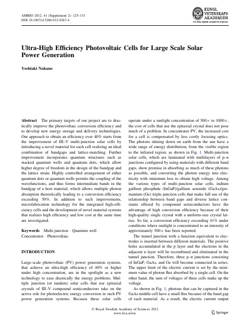
Ultra-High Efficiency Photovoltaic Cells for Large Scale Solar Power GenerationYoshiaki NakanoAbstract The primary targets of our project are to dras-tically improve the photovoltaic conversion efficiency and to develop new energy storage and delivery technologies. Our approach to obtain an efficiency over40%starts from the improvement of III–V multi-junction solar cells by introducing a novel material for each cell realizing an ideal combination of bandgaps and lattice-matching.Further improvement incorporates quantum structures such as stacked quantum wells and quantum dots,which allow higher degree of freedom in the design of the bandgap and the lattice strain.Highly controlled arrangement of either quantum dots or quantum wells permits the coupling of the wavefunctions,and thus forms intermediate bands in the bandgap of a host material,which allows multiple photon absorption theoretically leading to a conversion efficiency exceeding50%.In addition to such improvements, microfabrication technology for the integrated high-effi-ciency cells and the development of novel material systems that realizes high efficiency and low cost at the same time are investigated.Keywords Multi-junctionÁQuantum wellÁConcentratorÁPhotovoltaicINTRODUCTIONLarge-scale photovoltaic(PV)power generation systems, that achieve an ultra-high efficiency of40%or higher under high concentration,are in the spotlight as a new technology to ease drastically the energy problems.Mul-tiple junction(or tandem)solar cells that use epitaxial crystals of III–V compound semiconductors take on the active role for photoelectric energy conversion in such PV power generation systems.Because these solar cells operate under a sunlight concentration of5009to10009, the cost of cells that use the epitaxial crystal does not pose much of a problem.In concentrator PV,the increased cost for a cell is compensated by less costly focusing optics. The photons shining down on earth from the sun have a wide range of energy distribution,from the visible region to the infrared region,as shown in Fig.1.Multi-junction solar cells,which are laminated with multilayers of p–n junctions configured by using materials with different band gaps,show promise in absorbing as much of these photons as possible,and converting the photon energy into elec-tricity with minimum loss to obtain high voltage.Among the various types of multi-junction solar cells,indium gallium phosphide(InGaP)/gallium arsenide(GaAs)/ger-manium(Ge)triple-junction cells that make full use of the relationship between band gaps and diverse lattice con-stants offered by compound semiconductors have the advantage of high conversion efficiency because of their high-quality single crystal with a uniform-size crystal lat-tice.So far,a conversion efficiency exceeding41%under conditions where sunlight is concentrated to an intensity of approximately5009has been reported.The tunnel junction with a function equivalent to elec-trodes is inserted between different materials.The positive holes accumulated in the p layer and the electrons in the adjacent n layer will be recombined and eliminated in the tunnel junction.Therefore,three p–n junctions consisting of InGaP,GaAs,and Ge will become connected in series. The upper limit of the electric current is set by the mini-mum value of photonflux absorbed by a single cell.On the other hand,the sum of voltages of three cells make up the voltage.As shown in Fig.1,photons that can be captured in the GaAs middle cell have a smallflux because of the band gap of each material.As a result,the electric currentoutputAMBIO2012,41(Supplement2):125–131 DOI10.1007/s13280-012-0267-4from the GaAs cell theoretically becomes smaller than that of the others and determines the electric current output of the entire tandem cell.To develop a higher efficiency tandem cell,it is necessary to use a material with a band gap narrower than that of GaAs for the middle cell.In order to obtain maximum conversion efficiency for triple-junction solar cells,it is essential to narrow down the middle cell band gap to 1.2eV and increase the short-circuit current density by 2mA/cm 2compared with that of the GaAs middle cell.When the material is replaced with a narrower band gap,the output voltage will drop.However,the effect of improving the electric current balance out-performs this drop in output voltage and boosts the effi-ciency of the entire multi-junction cell.When a crystal with such a narrow band gap is grown on a Ge base material,lattice relaxation will occur in the middle of epitaxial crystal growth because the lattice constants of narrower band-gap materials are larger than that of Ge (as shown in Fig.2).As a result,the carrier transport properties will degrade due to dislocation.Researchers from the international research center Solar Quest,the University of Tokyo,aim to move beyond such material-related restrictions,and obtain materials and structures that have effective narrow band gaps while maintaining lattice matching with Ge or GaAs.To achieve this goal,we have taken three approaches as indicated in Fig.3.These approaches are explained in detail below.DILUTE NITROGEN-ADDED BULK CRYSTAL Indium gallium nitride arsenide (InGaNAs)is a bulk material consists of InGaAs,which contains several percent of nitrogen.InGaNAs has a high potential for achieving a narrow band gap while maintaining lattice matching with Ge or GaAs.However,InGaNAs has a fatal problem,that is,a drop in carrier mobility due to inhomogeneousdistribution of nitrogen (N).To achieve homogeneous solid solution of N in crystal,we have applied atomic hydrogen irradiation in the film formation process and addition of a very small amount of antimony (Sb)(Fig.3).The atomic hydrogen irradiation technology and the nitrogen radical irradiation technology for incorporating N efficiently into the crystal can be achieved only through molecular beam epitaxy (MBE),which is used to fabricate films under high vacuum conditions.(Nitrogen radical irradiation is a technology that irradiates the surface of a growing crystal with nitrogen atoms that are resolved by passing nitrogen through a plasma device attached to the MBE system.)Therefore,high-quality InGaNAs has been obtained only by MBE until now.Furthermore,as a small amount of Sb is also incorporated in a crystal,it is nec-essary to control the composition of five elements in the crystal with a high degree of accuracy to achieve lattice matching with Ge or GaAs.We have overcome this difficulty by optimizing the crystal growth conditions with high precision and devel-oped a cell that has an InGaNAs absorption layer formed on a GaAs substrate.The short-circuit current has increased by 9.6mA/cm 2for this cell,compared with a GaAs single-junction cell,by narrowing the band gap down to 1.0eV.This technology can be implemented not only for triple-junction cells,but also for higher efficiency lattice-matched quadruple-junction cells on a Ge substrate.In order to avoid the difficulty of adjusting the compo-sition of five elements in a crystal,we are also taking an approach of using GaNAs with a lattice smaller than that of Ge or GaAs for the absorption layer and inserting InAs with a large lattice in dot form to compensate for the crystal’s tensile strain.To make a solid solution of N uniformly in GaNAs,we use the MBE method for crystal growth and the atomic hydrogen irradiation as in the case of InGaNAs.We also believe that using 3D-shaped InAs dots can effectively compensate for the tensile strainthatFig.1Solar spectrum radiated on earth and photon flux collected by the top cell (InGaP),middle cell (GaAs),and bottom cell (Ge)(equivalent to the area of the filled portions in the figure)occurs in GaNAs.We have measured the characteristics of a single-junction cell formed on a GaAs substrate by using a GaNAs absorption layer with InAs dots inserted.Figure 4shows that we were able to succeed in enhancing the external quantum efficiency in the long-wavelength region (corresponding to the GaNAs absorp-tion)to a level equal to GaAs.This was done by extending the absorption edge to a longer wavelength of 1200nm,and increasing the thickness of the GaNAs layer by increasing the number of laminated InAs quantum dot layers.This high quantum efficiency clearly indicates that GaNAs with InAs dots inserted has the satisfactory quality for middle cell material (Oshima et al.2010).STRAIN-COMPENSATED QUANTUM WELL STRUCTUREIt is extremely difficult to develop a narrow band-gap material that can maintain lattice matching with Ge orGaAs unless dilute nitrogen-based materials mentioned earlier are used.As shown in Fig.2,the conventionally used material InGaAs has a narrower band gap and a larger lattice constant than GaAs.Therefore,it is difficult to grow InGaAs with a thickness larger than the critical film thickness on GaAs without causing lattice relaxation.However,the total film thickness of InGaAs can be increased as an InGaAs/GaAsP strain-compensated multi-layer structure by laminating InGaAs with a thickness less than the critical film thickness in combination with GaAsP that is based on GaAs as well,but has a small lattice constant,and bringing the average strain close to zero (Fig.3.).This InGaAs/GaAsP strain-compensated multilayer structure will form a quantum well-type potential as shown in Fig.5.The narrow band-gap InGaAs layer absorbs the long-wavelength photons to generate electron–hole pairs.When these electron–hole pairs go over the potential bar-rier of the GaAsP layer due to thermal excitation,the electrons and holes are separated by a built-in electricfieldFig.2Relationship between band gaps and lattice constants of III–V-based and IV-based crystalsto generate photocurrent.There is a high probability of recombination of electron–hole pairs that remain in the well.To avoid this recombination,it is necessary to take out the electron–hole pairs efficiently from the well and transfer them to n-type and p-type regions without allowing them to be recaptured into the well.Designing thequantumFig.3Materials and structures of narrow band-gap middle cells being researched by thisteamFig.4Spectral quantum efficiency of GaAs single-junction cell using GaNAs bulk crystal layer (inserted with InAs dots)as the absorption layer:Since the InAs dot layer and the GaNAs bulk layer are stacked alternately,the total thickness of GaNAs layers increases as the number of stacked InAs dot layers is increased.The solid line in the graph indicates the data of a reference cell that uses GaAs for its absorption layer (Oshima et al.2010)well structure suited for this purpose is essential for improving conversion efficiency.The high-quality crystal growth by means of the metal-organic vapor phase epitaxy (MOVPE)method with excellent ability for mass production has already been applied for InGaAs and GaAsP layers in semiconductor optical device applications.Therefore,it is technologically quite possible to incorporate the InGaAs/GaAsP quantum well structure into multi-junction solar cells that are man-ufactured at present,only if highly accurate strain com-pensation can be achieved.As the most basic approach related to quantum well structure design,we are working on fabrication of super-lattice cells with the aim of achieving higher efficiency by making the GaAsP barrier layer as thin as possible,and enabling carriers to move among wells by means of the tunnel effect.Figure 6shows the spectral quantum effi-ciency of a superlattice cell.In this example,the thickness of the GaAsP barrier layer is 5nm,which is not thin enough for proper demonstration of the tunnel effect.When the quantum efficiency in the wavelength range (860–960nm)that corresponds to absorption of the quan-tum well is compared between a cell,which has a con-ventionally used barrier layer and a thickness of 10nm or more,and a superlattice cell,which has the same total layer thickness of InGaAs,the superlattice cell demonstrates double or higher quantum efficiency.This result indicates that carrier mobility across quantum wells is promoted by even the partial use of the tunnel effect.By increasing the P composition in the GaAsP layer,the thickness of well (or the In composition)can be increased,and the barrier layer thickness can be reduced while strain compensation is maintained.A cell with higher quantum efficiency can befabricated while extending the absorption edge to the long-wavelength side (Wang et al.2010,2012).GROWTH TECHNIQUE FOR STRAIN-COMPENSATED QUANTUM WELLTo reduce the strain accumulated in the InGaAs/GaAsP multilayer structure as close to zero as possible,it is nec-essary to control the thickness and atomic content of each layer with high accuracy.The In composition and thickness of the InGaAs layer has a direct effect on the absorption edge wavelength and the GaAsP layer must be thinned to a satisfactory extent to demonstrate fully the tunnel effect of the barrier layer.Therefore,it is desirable that the average strain of the entire structure is adjusted mainly by the P composition of the GaAsP layer.Meanwhile,for MOVPE,there exists a nonlinear rela-tionship between the P composition of the crystal layer and the P ratio [P/(P ?As)]in the vapor phase precursors,which arises from different absorption and desorption phenomena on the surface.As a result,it is not easy to control the P composition of the crystal layer.To break through such a difficulty and promote efficient optimiza-tion of crystal growth conditions,we have applied a mechanism to evaluate the strain of the crystal layer during growth in real time by sequentially measuring the curvature of wafers during growth with an incident laser beam from the observation window of the reactor.As shown in Fig.7,the wafer curvature during the growth of an InGaAs/GaAsP multilayer structure indicates a periodic behavior.Based on a simple mechanical model,it has become clear that the time changes ofwaferFig.5Distribution of potential formed by the InGaAs/GaAsP strain-compensated multilayer structure:the narrow band-gap InGaAs layer is sandwiched between wide band-gap GaAsP layers and,as a result,it as quantum well-type potential distribution.In the well,electron–hole pairs are formed by absorption of long-wavelength photons and at the same time,recombination of electrons and holes takes place.The team from Solar Quest is focusing on developing a superlattice structure with the thinnest GaAsP barrier layercurvature are proportionate to the strain of the crystal layer relative to a substrate during the growing process.One vibration cycle of the curvature is same as the growth time of an InGaAs and GaAsP pair (Sugiyama et al.2011).Therefore,the observed vibration of the wafer curvature reflects the accumulation of the compression strain that occurs during InGaAs growth and the release of the strain that occurs during GaAsP growth.When the strain is completely compensated,the growth of the InGaAs/GaAsP pair will cause this strain to return to the initial value and the wafer curvature will vibrate with the horizontal line as the center.As shown in Fig.7,strain can be compensated almost completely by adjusting the layer structure.Only by conducting a limited number of test runs,the use of such real-time observation technology of the growth layer enables setting the growth conditions for fabricating the layer structure for which strain has been compensated with highaccuracy.Fig.6Spectral quantum efficiency of GaAs single-junction cell using InGaAs/GaAsP superlattice as theabsorption layer:This structure consists of 60layers of InGaAs quantum wells.The graph also shows data of a reference cell that uses GaAs for its absorption layer (Wang et al.2010,2012)Fig.7Changes in wafer curvature over time during growth of the InGaAs/GaAsP multilayer structure.This graph indicates the measurement result and the simulation result of the curvature based on the layer structure(composition ?thickness)obtained by X-ray diffraction.Since compressive strain is applied during InGaAs growth,the curvature decreases as time passes.On the other hand,since tensile strain is applied during GaAsP growth,the curvature changes in the oppositedirection (Sugiyama et al.2011)FUTURE DIRECTIONSIn order to improve the conversion efficiency by enhancing the current matching of multi-junction solar cells using III–V compound semiconductors,there is an urgent need to create semiconductor materials or structures that can maintain lattice matching with Ge or GaAs,and have a band gap of1.2eV.As for InGaNAs,which consists of InGaAs with several percent of nitrogen added,we have the prospect of extending the band edge to1.0eV while retaining sufficient carrier mobility for solar cells by means of atomic hydrogen irradiation and application of a small quantity of Sb during the growth process.In addition,as for GaNAs bulk crystal containing InAs dots,we were able to extend the band edge to1.2eV and produce a high-quality crystal with enoughfilm thickness to achieve the quantum efficiency equivalent to that of GaAs.These crystals are grown by means of MBE. Therefore,measures that can be used to apply these crys-tals for mass production,such as migration to MOVPE, will be investigated after demonstrating their high effi-ciency by embedding these crystals into multi-junction cells.As for the InGaAs/GaAsP strain-compensated quantum well that can be grown using MOVPE,we are working on the development of a thinner barrier layer while compen-sating for the strain with high accuracy by real-time observation of the wafer curvature.We have had the prospect of achieving a quantum efficiency that will sur-pass existing quantum well solar cells by promoting the carrier transfer within the multilayer quantum well struc-ture using the tunnel effect.As this technology can be transferred quite easily to the existing multi-junction solar cell fabrication process,we strongly believe that this technology can significantly contribute to the efficiency improvement of the latest multi-junction solar cells. REFERENCESOshima,R.,A.Takata,Y.Shoji,K.Akahane,and Y.Okada.2010.InAs/GaNAs strain-compensated quantum dots stacked up to50 layers for use in high-efficiency solar cell.Physica E42: 2757–2760.Sugiyama,M.,K.Sugita,Y.Wang,and Y.Nakano.2011.In situ curvature monitoring for metalorganic vapor phase epitaxy of strain-balanced stacks of InGaAs/GaAsP multiple quantum wells.Journal of Crystal Growth315:1–4.Wang,Y.,Y.Wen,K.Watanabe,M.Sugiyama,and Y.Nakano.2010.InGaAs/GaAsP strain-compensated superlattice solar cell for enhanced spectral response.In Proceedings35th IEEE photovoltaic specialists conference,3383–3385.Wang,Y.P.,S.Ma,M.Sugiyama,and Y.Nakano.2012.Management of highly-strained heterointerface in InGaAs/GaAsP strain-balanced superlattice for photovoltaic application.Journal of Crystal Growth.doi:10.1016/j.jcrysgro.2011.12.049. AUTHOR BIOGRAPHYYoshiaki Nakano(&)is Professor and Director General of Research Center for Advanced Science and Technology,the University of Tokyo.His research interests include physics and fabrication tech-nologies of semiconductor distributed feedback lasers,semiconductor optical modulators/switches,monolithically integrated photonic cir-cuits,and high-efficiency heterostructure solar cells.Address:Research Center for Advanced Science and Technology, The University of Tokyo,4-6-1Komaba,Meguro-ku,Tokyo153-8904,Japan.e-mail:nakano@rcast.u-tokyo.ac.jp。
新能源公司光伏控制器和逆变器产品手册(中英文)

特变电工新能源控制器和逆变器系列产品1.小功率充电控制器系列Small Power Charge Controller Series型号TypeXNY-TZ12/24 10BⅡXNY-TZ12/24 20BⅡXNY-TZ12/2430BⅡXNY-TZ12/24 40BⅡ充电输入Charge Input组件最大开路电压Maximum OpenCircuit Voltage ofSolar Module25V / 50V额定输入电流Rated Input Current10 A 20 A 30 A 40 A蓄电池Storage Battery标称电压Nominal Voltage12V / 24V浮充电压Float Voltage13.7V / 27.4V过充电压Over Charge Voltage14.3V / 28.6V欠压电压Lack of Voltage10.8V / 21/6V直流输出DC Output输出电压Output Voltage10.8-14.3V / 22.0-28.6V输出最大电流Maximum OutputCurrent20A 40A提示关断电压Prompt for cuttingvoltage11.5V / 23.0V欠压关断Cutting for lack ofvoltage10.8V / 21.6V欠压恢复LV resumption13.0V / 26.0V显示Display LED指示indication系统运行、欠压提示、欠压保护、过充保护、负载保护、短路保护Systematic operation, LV indication, LV protection, over chargeprotection, loads protection, short circuit protection液晶显示(可选)LCD display(optional)充电电压、充电电流、蓄电池电压、蓄电池容量、输出电流Charge voltage, charge current, voltage of storage battery,capacity of storage battery, output current报警保护Alarm Protections输入反接保护Input reverseconnectionprotection有Yes输出短路保护Output short circuitprotection有Yes蓄电池欠压保护LV protection forstorage battery有Yes蓄电池反接保护Reverse connectionprotection forstorage battery有Yes其它项Other Items防护等级Defend rank符合DIN EN60529规定IP22或IP65标准In compliance with regulations of DIN EN60529 and standards ofIP22 or IP65充电模式Charge modePWM脉宽调制,恒流-恒压模式,蓄电池自动维护功能PWM ,constant current—constant voltage, function of automaticprotection for storage battery散热方式Radiating mode 自冷Automatic cooling工作模式Working mode普通控制器、光控开+时控关、时控开+光控关General controller, lighting for on+ timing for off, timing for on +lighting for on自耗电Self electricityconsumption< 10 mA < 15mA环境Environment使用环境温度Environmentaltemperature-10℃ --45℃使用环境湿度Ambient humidity0--90%,不结露no dew海拔Altitude≤4500m体积Volume 长*宽*高Length*Width*Height120*90*45 180*110*55 180*110*55 180*110*552.小功率户用电源系列Small Power Electrical Source Series for Home Use型号Type XNY-TNX 12/24 300 L III型XNY-TNX 12/24 500 L III型充电输入Charge Input组件最大开路电压Maximum Open CircuitVoltage of SolarModule25V / 50V额定输入电流Rated Input Current25A/12.5A 50A/25A蓄电标称电压Nominal Voltage12V / 24V池Storage Battery浮充电压Float Voltage13.7V / 27.4V过充电压Over Charge Voltage14.3V / 28.6V欠压电压Lack of Voltage10.8V / 21/6V直流输出DC Output输出电压Output Voltage10.8-14.3V / 22.0-28.6V输出最大电流Maximum OutputCurrent20A 40A欠压关断Cutting for lack ofvoltage10.8V / 21.6V欠压恢复LV resumption13.0V / 26.0V交流输出AC Output输出电压Output VoltageAC220V±10%输出波形Output Wave Shape修正正弦波Modified Sine Wave输出频率Output Frequency50±1 Hz额定输出功率Rated Output Power300W 600W转换效率Conversion Efficiency>94%显示Display LED显示充电指示、直流负载输出、欠压、过压等状态指示.Charge Indication, DC Load Output, Lack of Voltage, OverVoltage and other status indication环境Environment温度Temperature-10℃—45℃湿度Humidity0—90%,不结露no dew海拔Altitude≤4500m外形Appearance参考重量Reference Weight30Kg(不带蓄电池)Not including Storage Battery参考尺寸Reference Dimension430*320*1603.小功率逆变器系列Small Power Inverter Series型号Type XNY-NS 48V 1K B I XNY-NS 24V 600 B I直流输入DC Input额定输入电压Rated input voltage48V 24V 额定输入电流Rated input current19A 23A 输入直流电压允许范围Allowed input DC voltage scope42.7V—58V 21.3V—29V开机电压范围Voltage scope of starting upequipments47V—58V 23.5V—29V欠压告警点LV alarm point46V 23V 过压告警点OV alarm point54V 27V 反灌杂音电流Anti-noise current≤10%≤10%交流输出AC Output额定容量(VA)Rated capacity1000VA 600VA 额定输出功率(W)Rated output power800W 500W 额定输出电压及频率Rated output voltage andfrequency220Vac,50Hz 220Vac,50Hz额定输出电流(A)Rated output current4.5A 2.7A输出电压精度(Vac)Output voltage precision220±5%输出频率精度(Hz)Output frequency precision50±1%波形失真率(THD)(线性负载)Rate of wave distortion(Linearity loads)≤2%动态响应时间(负载0←→100%)Dynamic response speed5S过载能力Overload capability120%,2分钟two minutes150%,15秒钟15seconds 逆变效率(80%阻性负载)Inverting efficiency80% resistive loads≥90%使用环境温度Ambient temperature-10℃ -- +40℃湿度Humidity0--90%,不结露no dew 使用海拔(m)Altitude≤4500保护功能Protection Function输入欠压保护Input LV protection输入过压保护Input OV protection输出过载保护Output overload protection输出短路保护Output Short Circuit Protection4. -48V通讯电源系列48V Communication Power Supply Series型号TypeXNY-CT48 – 120XNY-CT48 – 160XNY-CT48 -200XNY-CT48 -300输入特性Input Characteristics输入电压范围Input voltagescope0~100V输入方式Input mode 多路many loops 额定输入电压Rated inputvoltage-68V蓄电池电压级别voltage rank ofstorage battery-48V控制器性能Performances ofcharger太阳能输入接口Solar inputterminal3路3loops 4路4loops 5路5loops 8路8loops额定充电电流Rated chargecurrent120A 160A 200A 300A单路额定充电电流Rated chargecurrent of singleloop40A欠压关断Cutting for lack ofvoltage-43.2V(-43.0—-47.0V constant adjustable)欠压恢复LV resumption-53.0V(-52.0—-54.4V constant adjustable)浮充电压Float voltage-56.0V(-52.0—-56.0V constant adjustable)均充电压Average voltage-58.0V(-54.0—-58.0V constant adjustable)高压关断Cutting forhigh-voltage-60.0V(-58.0—-62.0V constant adjustable)温度补偿系数Temperaturecompensationcoefficient-4mV/cell/℃(-1—-5mV/cell/℃ constant adjustable)放电输出接口Discharge outputterminal2circuits路(每路最大60A)Max. 60A each circuit静态工作电流Static workingcurrent≤60mA显示Display LCD显示display充电电压、充电电流、电池电压、电池容量、输出电压、输出电流Charge voltage, charge current, voltage of storagebattery, capacity of storage battery, output voltage,output current通信Communication RS422/RS485历史数据存储100天,参数可修改,符合RS422/RS485标准通信接口协议。
(完整word版)逆变器外文文献及翻译

Inverter1 IntroductionAn inverter is an electrical device that converts direct current (DC) to alternating current (AC); the converted AC can be at any required voltage and frequency with the use of appropriate transformers, switching, and control circuits.Solid-state inverters have no moving parts and are used in a wide range of applications, from small switching power supplies in computers, to large electric utility high-voltage direct current applications that transport bulk power. Inverters are commonly used to supply AC power from DC sources such as solar panels or batteries.There are two main types of inverter. The output of a modified sine wave inverter is similar to a square wave output except that the output goes to zero volts for a time before switching positive or negative. It is simple and low cost and is compatible with most electronic devices, except for sensitive or specialized equipment, for example certain laser printers. A pure sine wave inverter produces a nearly perfect sine wave output (<3% total harmonic distortion) that is essentially the same as utility-supplied grid power. Thus it is compatible with all AC electronic devices. This is the type used in grid-tie inverters. Its design is more complex, and costs 5 or 10 times more per unit power The electrical inverter is a high-power electronic oscillator. It is so named because early mechanical AC to DC converters were made to work in reverse, and thus were "inverted", to convert DC to AC.The inverter performs the opposite function of a rectifier.2 Applications2.1 DC power source utilizationAn inverter converts the DC electricity from sources such as batteries, solar panels, or fuel cells to AC electricity. The electricity can be at any required voltage; in particular it can operate AC equipment designed for mains operation, or rectified to produce DC at any desired voltageGrid tie inverters can feed energy back into the distribution network because they produce alternating current with the same wave shape and frequency as supplied by the distribution system. They can also switch off automatically in the event of a blackout.Micro-inverters convert direct current from individual solar panels into alternating current for the electric grid. They are grid tie designs by default.2.2 Uninterruptible power suppliesAn uninterruptible power supply (UPS) uses batteries and an inverter to supply AC power when main power is not available. When main power is restored, a rectifier supplies DC power to recharge the batteries.2.3 Induction heatingInverters convert low frequency main AC power to a higher frequency for use in induction heating. To do this, AC power is first rectified to provide DC power. The inverter then changes the DC power to high frequency AC power.2.4 HVDC power transmissionWith HVDC power transmission, AC power is rectified and high voltage DC power is transmitted to another location. At the receiving location, an inverter in a static inverter plant converts the power back to AC.2.5 Variable-frequency drivesA variable-frequency drive controls the operating speed of an AC motor by controlling the frequency and voltage of the power supplied to the motor. An inverter provides the controlled power. In most cases, the variable-frequency drive includes a rectifier so that DC power for the inverter can be provided from main AC power. Since an inverter is the key component, variable-frequency drives are sometimes called inverter drives or just inverters.2.6 Electric vehicle drivesAdjustable speed motor control inverters are currently used to power the traction motors in some electric and diesel-electric rail vehicles as well as some battery electric vehicles and hybrid electric highway vehicles such as the Toyota Prius and Fisker Karma. Various improvements in inverter technology are being developed specifically for electric vehicle applications.[2] In vehicles with regenerative braking, the inverter also takes power from the motor (now acting as a generator) and stores it in the batteries.2.7 The general caseA transformer allows AC power to be converted to any desired voltage, but at the same frequency. Inverters, plus rectifiers for DC, can be designed to convert from any voltage, AC or DC, to any other voltage, also AC or DC, at any desired frequency. The output power can never exceed the input power, but efficiencies can be high, with a small proportion of the power dissipated as waste heat.3 Circuit description3.1 Basic designsIn one simple inverter circuit, DC power is connected to a transformer through the centre tap of the primary winding. A switch is rapidly switched back and forth to allowcurrent to flow back to the DC source following two alternate paths through one end of the primary winding and then the other. The alternation of the direction of current in the primary winding of the transformer produces alternating current (AC) in the secondary circuit.The electromechanical version of the switching device includes two stationary contacts and a spring supported moving contact. The spring holds the movable contact against one of the stationary contacts and an electromagnet pulls the movable contact to the opposite stationary contact. The current in the electromagnet is interrupted by the action of the switch so that the switch continually switches rapidly back and forth. This type of electromechanical inverter switch, called a vibrator or buzzer, was once used in vacuum tube automobile radios. A similar mechanism has been used in door bells, buzzers and tattoo guns.As they became available with adequate power ratings, transistors and various other types of semiconductor switches have been incorporated into inverter circuit designs 3.2 Output waveformsThe switch in the simple inverter described above, when not coupled to an output transformer, produces a square voltage waveform due to its simple off and on nature as opposed to the sinusoidal waveform that is the usual waveform of an AC power supply. Using Fourier analysis, periodic waveforms are represented as the sum of an infinite series of sine waves. The sine wave that has the same frequency as the original waveform is called the fundamental component. The other sine waves, called harmonics, that are included in the series have frequencies that are integral multiples of the fundamental frequency.The quality of output waveform that is needed from an inverter depends on thecharacteristics of the connected load. Some loads need a nearly perfect sine wave voltage supply in order to work properly. Other loads may work quite well with a square wave voltage.3.3 Three phase invertersThree-phase inverters are used for variable-frequency drive applications and for high power applications such as HVDC power transmission. A basic three-phase inverter consists of three single-phase inverter switches each connected to one of the three load terminals. For the most basic control scheme, the operation of the three switches is coordinated so that one switch operates at each 60 degree point of the fundamental output waveform. This creates a line-to-line output waveform that has six steps. The six-step waveform has a zero-voltage step between the positive and negative sections of the square-wave such that the harmonics that are multiples of three are eliminated as described above. When carrier-based PWM techniques are applied to six-step waveforms, the basic overall shape, or envelope, of the waveform is retained so that the 3rd harmonic and its multiples are cancelled4 History4.1 Early invertersFrom the late nineteenth century through the middle of the twentieth century, DC-to-AC power conversion was accomplished using rotary converters or motor-generator sets (M-G sets). In the early twentieth century, vacuum tubes and gas filled tubes began to be used as switches in inverter circuits. The most widely used type of tube was the thyratron.The origins of electromechanical inverters explain the source of the term inverter. Early AC-to-DC converters used an induction or synchronous AC motor direct-connected to a generator (dynamo) so that the generator's commutator reversed its connections atexactly the right moments to produce DC. A later development is the synchronous converter, in which the motor and generator windings are combined into one armature, with slip rings at one end and a commutator at the other and only one field frame. The result with either is AC-in, DC-out. With an M-G set, the DC can be considered to be separately generated from the AC; with a synchronous converter, in a certain sense it can be considered to be "mechanically rectified AC". Given the right auxiliary and control equipment, an M-G set or rotary converter can be "run backwards", converting DC to AC. Hence an inverter is an inverted converter.4.2 Controlled rectifier invertersSince early transistors were not available with sufficient voltage and current ratings for most inverter applications, it was the 1957 introduction of the thyristor or silicon-controlled rectifier (SCR) that initiated the transition to solid state inverter circuits.The commutation requirements of SCRs are a key consideration in SCR circuit designs. SCRs do not turn off or commutate automatically when the gate control signal is shut off. They only turn off when the forward current is reduced to below the minimum holding current, which varies with each kind of SCR, through some external process. For SCRs connected to an AC power source, commutation occurs naturally every time the polarity of the source voltage reverses. SCRs connected to a DC power source usually require a means of forced commutation that forces the current to zero when commutation is required. The least complicated SCR circuits employ natural commutation rather than forced commutation. With the addition of forced commutation circuits, SCRs have been used in the types of inverter circuits describedIn applications where inverters transfer power from a DC power source to an AC above.power source, it is possible to use AC-to-DC controlled rectifier circuits operating in the inversion mode. In the inversion mode, a controlled rectifier circuit operates as a line commutated inverter. This type of operation can be used in HVDC power transmission systems and in regenerative braking operation of motor control systems.Another type of SCR inverter circuit is the current source input (CSI) inverter. A CSI inverter is the dual of a six-step voltage source inverter. With a current source inverter, the DC power supply is configured as a current source rather than a voltage source. The inverter SCRs are switched in a six-step sequence to direct the current to a three-phase AC load as a stepped current waveform. CSI inverter commutation methods include load commutation and parallel capacitor commutation. With both methods, the input current regulation assists the commutation. With load commutation, the load is a synchronous motor operated at a leading power factor. As they have become available in higher voltage and current ratings, semiconductors such as transistors or IGBTs that can be turned off by means of control signals have become the preferred switching components for use in inverter circuits.4.3 Rectifier and inverter pulse numbersRectifier circuits are often classified by the number of current pulses that flow to the DC side of the rectifier per cycle of AC input voltage. A single-phase half-wave rectifier is a one-pulse circuit and a single-phase full-wave rectifier is a two-pulse circuit. A three-phase half-wave rectifier is a three-pulse circuit and a three-phase full-wave rectifier is a six-pulse circuit。
太阳能光伏电池中英文对照外文翻译文献
太阳能光伏电池中英文对照外文翻译文献中英文对照翻译光伏系统中蓄电池的充电保护IC电路设计1.引言太阳能作为一种取之不尽、用之不竭的能源越来越受到重视。
太阳能发电已经在很多国家和地区开始普及,太阳能照明也已经在我国很多城市开始投入使用。
作为太阳能照明的一个关键部分,蓄电池的充电以及保护显得尤为重要。
由于密封免维护铅酸蓄电池具有密封好、无泄漏、无污染、免维护、价格低廉、供电可靠,在电池的整个寿命期间电压稳定且不需要维护等优点,所以在各类需要不间断供电的电子设备和便携式仪器仪表中有着广泛的应用。
采用适当的浮充电压,在正常使用(防止过放、过充、过流)时,免维护铅酸蓄电池的浮充寿命可达12~16年,如果浮充电压偏差5%则使用寿命缩短1/2。
由此可见,充电方式对这类电池的使用寿命有着重大的影响。
由于在光伏发电中,蓄电池无需经常维护,因此采用正确的充电方式并采用合理的保护方式,能有效延长蓄电池的使用寿命。
传统的充电和保护IC 是分立的,占用而积大并且外围电路复杂。
目前,市场上还没有真正的将充电与保护功能集成于单一芯片。
针对这个问题,设计一种集蓄电池充电和保护功能于一身的IC是十分必要的。
2.系统设计与考虑系统主要包括两大部分:蓄电池充电模块和保护模块。
这对于将蓄电池作为备用电源使用的场合具有重要意义,它既可以保证外部电源给蓄电池供电,又可以在蓄电池过充、过流以及外部电源断开蓄电池处于过放状态时提供保护,将充电和保护功能集于一身使得电路简化,并且减少宝贵的而积资源浪费。
图1是此Ic在光伏发电系统中的具体应用,也是此设计的来源。
免维护铅酸蓄电池的寿命通常为循环寿命和浮充寿命,影响蓄电池寿命的因素有充电速率、放电速率和浮充电压。
某些厂家称如果有过充保护电路,充电率可以达到甚至超过2C(C为蓄电池的额定容量),但是电池厂商推荐的充电率是C/20~C/3。
电池的电压与温度有关,温度每升高1℃,单格电池电压下降4 mV,也就是说电池的浮充电压有负的温度系数-4 mV/℃。
光伏发电技术中英文资料外文翻译文献

光伏发电技术中英文资料外文翻译文献Research Article 1: Title of the ArticleAbstractResearch Article 2: Title of the ArticleAbstractThis research article focuses on the environmental impact of PV technology. It explains how solar panels convert sunlight into electricity and highlights the role of PV systems in reducing greenhouse gas emissions. The article discusses the benefits and challenges associated with PV technology, including its dependence on sunlight, land requirements, and recyclability of materials. It also examines the life cycle assessment (LCA) of PV systems to evaluate their overall environmental performance. The research concludes by suggesting strategies to mitigate the environmental impact of PV technology, suchas improving panel efficiency and implementing responsible recycling practices.Research Article 3: Title of the ArticleAbstractThis article explores the economic aspects of PV technology. It analyzes the cost of installing and maintaining PV systems, including considerations for equipment, installation, and operation. The research discusses various financial incentives, such as government subsidies and tax credits, that promote the adoption of PV technology. It also highlights the economic benefits of PV systems, including job creation and energy independence. The article concludes by discussing the future potential of PV technology in reducing energy costs and stimulating economic growth.Research Article 4: Title of the ArticleAbstractThe focus of this research article is on the technical advancements in PV technology. It discusses the development of new materials and manufacturing processes to improve the efficiency and reliability of solar panels. The article explores the integration of PV systems with smart grid technology and how it enables better management of electricity generation and consumption. It also highlights the role of artificial intelligence and machine learning in optimizing PV system performance. The research concludes by suggesting future research directions in PV technology, such as exploring nanomaterials and enhancing the intelligence of PV systems.Conclusion总结这份文献收录了关于光伏发电技术的各个方面的研究,涵盖了与环境影响、经济考量和技术进展相关的主题。
光伏逆变器说明书V2.0 英文

4Hale Waihona Puke 678123456
78910
123
456 78
9
10 Installation bracket cutout template
Installation bracket cutout template
11
2
Installation bracket
cutout template Installation bracket
V -p v 1:000.0V I -p v 1:000.0A V -p v 2:000.0V 01.A 001MENU A l ar m
p
h MENU
M a i n
M e n u M o n i t P a r a m H i s t o r y S t a t i s t i c s S e t u p
S O L A R I N V E R T E R
I n i t i a l i n g……W a i t i n g
>>>>>>>
C o u n t r y:U n s e t
Germany
U K
A u s t r a l i a G r e e c e
D e n m a r k
H o l l a n d
(4) Hang the inverter on the installation bracket and ensure it is locked-in as figure 3.10 shows;
(5) Fix the screws into the screw-holes to ensure fastened installation.
- 1、下载文档前请自行甄别文档内容的完整性,平台不提供额外的编辑、内容补充、找答案等附加服务。
- 2、"仅部分预览"的文档,不可在线预览部分如存在完整性等问题,可反馈申请退款(可完整预览的文档不适用该条件!)。
- 3、如文档侵犯您的权益,请联系客服反馈,我们会尽快为您处理(人工客服工作时间:9:00-18:30)。
外文翻译文献中英文对照资料外文翻译文献光伏逆变器的发展及优势结构与工作原理逆变器是一种由半导体器件组成的电力调整装置,主要用于把直流电力转换成交流电力。
一般由升压回路和逆变桥式回路构成。
升压回路把太阳电池的直流电压升压到逆变器输出控制所需的直流电压;逆变桥式回路则把升压后的直流电压等价地转换成常用频率的交流电压。
逆变器主要由晶体管等开关元件构成,通过有规则地让开关元件重复开 -关( ON-OFF),使直流输入变成交流输出。
当然,这样单纯地由开和关回路产生的逆变器输出波形并不实用。
一般需要采用高频脉宽调制( SPWM),使靠近正弦波两端的电压宽度变狭,正弦波中央的电压宽度变宽,并在半周期内始终让开关元件按一定频率朝一方向动作,这样形成一个脉冲波列(拟正弦波)。
然后让脉冲波通过简单的滤波器形成正弦波。
逆变器不仅具有直交流变换功能,还具有最大限度地发挥太阳电池性能的功能和系统故障保护功能。
归纳起来有自动运行和停机功能、最大功率跟踪控制功能、防单独运行功能(并网系统用)、自动电压调整功能(并网系统用)、直流检测功能(并网系统用)、直流接地检测功能(并网系统用)。
这里简单介绍自动运行和停机功能及最大功率跟踪控制功能。
1、自动运行和停机功能早晨日出后,太阳辐射强度逐渐增强,太阳电池的输出也随之增大,当达到逆变器工作所需的输出功率后,逆变器即自动开始运行。
进入运行后,逆变器便时时刻刻监视太阳电池组件的输出,只要太阳电池组件的输出功率大于逆变器工作所需的输出功率,逆变器就持续运行;直到日落停机,即使阴雨天逆变器也能运行。
当太阳电池组件输出变小,逆变器输出接近 0 时,逆变器便形成待机状态。
2、最大功率跟踪控制功能太阳电池组件的输出是随太阳辐射强度和太阳电池组件自身温度(芯片温度)而变化的。
另外由于太阳电池组件具有电压随电流增大而下降的特性,因此存在能获取最大功率的最佳工作点。
太阳辐射强度是变化着的,显然最佳工作点也是在变化的。
相对于这些变化,始终让太阳电池组件的工作点处于最大功率点,系统始终从太阳电池组件获取最大功率输出,这种控制就是最大功率跟踪控制。
太阳能发电系统用的逆变器的最大特点就是包括了最大功率点跟踪( MPPT)这一功能。
工作环境与要求:1.光伏逆变器要求具有较高的效率。
由于 2011 年太阳电池的价格偏高,为了最大限度地利用太阳电池,提高系统效率,必须设法提高逆变器的效率。
2.光伏逆变器要求具有较高的可靠性。
2012 年光伏发电系统主要用于边远地区,许多电站无人值守和维护,这就要求逆变器具有合理的电路结构,严格的元器件筛选,并要求逆变器具备各种保护功能,如输入直流极性接反保护,交流输出短路保护,过热、过载保护等。
3.光伏逆变器要求直流输入电压有较宽的适应范围,由于太阳电池的端电压随负载和日照强度而变化,蓄电池虽然对太阳电池的电压具有重要作用,但由于蓄电池的电压随蓄电池剩余容量和内阻的变化而波动,特别是当蓄电池老化时其端电压的变化范围很大,如 12V 蓄电池,其端电压可在 10V~16V 之间变化,这就要求逆变器必须在较大的直流输入电压范围内保证正常工作,并保证交流输出电压的稳定。
4.光伏逆变器在中、大容量的光伏发电系统中,逆变电源的输出应为失真度较小的正弦波。
这是由于在中、大容量系统中,若采用方波供电,则输出将含有较多的谐波分量,高次谐波将产生附加损耗,许多光伏发电系统的负载为通信或仪表设备,这些设备对电网品质有较高的要求,当中、大容量的光伏发电系统并网运行时,为避免与公共电网的电力污染,也要求逆变器输出正弦波电流。
发展前景光伏并网发电系统就是太阳能组件产生的直流电经过并网逆变器转换成符合市电电网要求的交流电这后直接接入公共电网。
光伏并网发电系统有集中式大型并网电站一般都是国家级电站,主要特点是将所发电能直接输送到电网,由电网统一调配向用户供电;也有分散式小型并网发电系统,特别是光伏建筑一体化发电系统,是并网发电的主流。
1、有逆流并网光伏发电系统有逆流并网光伏发电系统:当太阳能光伏系统发出的电能充裕时,可将剩余电能馈入公共电网,向电网供电(卖电);当太阳能光伏系统提供的电力不足时,由电能向负载供电(买电)。
由于向电网供电时与电网供电的方向相反,所以称为有逆流光伏发电系统。
2、无逆流并网光伏发电系统无逆流并网光伏发电系统:太阳能光伏发电系统即使发电充裕也不向公共电网供电,但当太阳能光伏系统供电不足时,则由公共电网向负载供电。
3、切换型并网光伏发电系统所谓切换型并网光伏发电系统,实际上是具有自动运行双向切换的功能。
一是当光伏发电系统因多云、阴雨天及自身故障等导致发电量不足时,切换器能自动切换到电网供电一侧,由电网向负载供电二是当电网因为某种原因实然停电时,光伏系统可以自动切换使电网与光伏系统分离,成为独立光伏发电系统工作状态。
有些切换型光伏发电系统,还可以在需要时断开为一般负载的供电,接通对应急负载的供电。
一般切换型并网发电系统都带有储能装置。
4、有储能装置的并网光伏发电系统有储能装置的并网光伏发电系统:就是在上述几类光伏发电系统中根据需要配置储能装置。
带有储能装置的光伏系统主动性较强,当电网出现停电、限电及故障时,可独立运行,正常向负载供电。
因此带有储能装置的并网光伏发电系统可以作为紧急通信电源、医疗设备、加油站、避难场所指示及照明等重要或应急负载的供电系统。
优势1)利用清洁干净、可再生的自然能源太阳能发电,不耗用不可再生的、资源有限的含碳化石能源,使用中无温室气体和污染物排放,与生态环境和谐,符合经济社会可持续发展战略。
(2)所发电能馈入电网,以电网为储能装置,省掉蓄电池,比独立太阳能光伏系统的建设投资可减少达 35%一 45%,从而使发电成本大为降低。
省掉蓄电池避免了蓄电池的二次污染,并可提高系统的平均无故障时间。
(3)光伏电池组件与建筑物完美结合,既可发电又能作为建筑材料和装饰材料,使物质资源充分利用发挥多种功能,不但有利于降低建设费用,并且还使建筑物科技含量提高,增加 "卖点 "。
(4)分布式建设,就近就地分散发供电,进入和退出电网灵活,既有利于增强电力系统抵御战争和灾害的能力,又有利于改善电力系统的负荷平衡,并可降低线路损耗。
(5)可起调峰作用。
联网太阳能光伏系统是世界各发达国家在光伏应用领域竞相发展的热点和重点,是世界太阳能光伏发电的主流发展趋势,市场巨大,前景广阔。
The development and advantage of photovoltaic inverterStructure and working principleInverter is a kind of the semiconductor device composed of power adjusting device, mainly used for the dc power into ac power. Generally the booster circuit and inverter bridge circuit composition. Booster circuit the solar cell dc voltage booster to the inverter output control the dc voltage; Inverter bridge circuit is the booster of dc voltage equivalent to convert common frequency ac voltage. Inverter is mainly composed of transistor and switch component is formed, and through the regular to switch element repeat on-off (ON - OFF), make dc input into ac output. Of course, this simply by on or off circuit to produce the inverter output waveform is not practical. General need to adopt high-frequency pulse width modulation (SPWM), close sine wave the voltage across the width change narrow, central sine wave voltage width broaden, and in the half period always let the switch element according to certain frequency in a direction action, so that form a pulse wave train (quasi sine wave). Then let the pulse wave through the simple filter form sine wave.Inverter not only has direct communication mapping function, but also has maximize solar cell performance function and system fault protection function. To sum up automatic operation and shutdown function,maximum power tracking control function, prevent run separately function (grid system), automatic voltage regulation function (grid system), the dc detection function (grid system), the dc grounding detection function (grid system). Here introduce automatic operation and stop function and maximum power tracking control function.1automatic operation and stop functionThe sunrise in the morning, the sun radiation intensity increasing, solar cell output has increased, when the inverter to the output power, the inverter automatically start running. Enter after the operation, the inverter and every minute monitoring solar cell module, as long as the output of the solar cell module the output power of the inverter is greater than the output power, inverter is continuous running; Until sunset stop, even if the day of overcast and rainy inverter can also run. When solar cell module output diminish, inverter output close to zero, inverter and standby state formation.2the most high power tracking control functionThe output of the solar cell module with solar radiation intensity and solar cell module itself temperature (chip temperature) and change. Plus, because of solar cell module has the voltage with current increase and thecharacteristics of the decline, and therefore there are can get the most high power best working point. Solar radiation intensity is changing, obviously the best working point is also changing. Relative to these changes, always let solar cell module of the working point in the maximum power point, the system always from the solar cell module for maximum power output, this control is the most high power tracking control. Solar power system with inverter is the biggest characteristic of including the maximum power point tracking (MPPT) this function.Working environment and requirements:1. Photovoltaic inverter requirements with high efficiency. The 2011 solar cell price is on the high side, in order to make the best use of solar cell, and enhanced the system efficiency, must try to improve the efficiency of the inverter.2. Photovoltaic inverter are required to have high reliability. 2012 pv power generation system is mainly used in remote areas, many power station unattended and maintenance, which requires the inverter instruments have reasonable circuit structure, strict components selection, and requirements for inverter instruments of various protection functions, such as input dc polarity meet anti protection, acoutput short circuit protection, heat, overload protection, etc.3.Photovoltaic inverter for dc input voltage has a wide application range, becauset he sun battery terminal voltage with load and sunshine intensity and change, battery although to solar cell voltage plays an important role, but due to the battery voltage with battery residual capacity and the change of resistance and fluctuation, especially when battery voltage across the age range change is very big, such as 12 v battery, the terminal voltage can be in 10 v ~ 16 v changes between, which requires the inverter must be in large dc input voltage range ensure normal work, and ensure the stability of the ac output voltage.4.Photovoltaic inverter in medium and large capacity of photovoltaic power generation system, the output of the inverter power supply should be distortion smaller sine wave. This is due in large capacity system, if you use the square wave power supply, the output will contain more harmonic component, the high harmonics will generate additional loss, a lot of photovoltaic power generation system load for communication or instrument equipment, the equipment to power quality have higher requirements, and large capacity of photovoltaic power generation system parallel operation, to avoid and public electricity from the grid pollution, also requires inverter output sine wave current. Development prospectPhotovoltaic (PV) grid generation system is solar energy components produced by dc grid inverter converted to conform to the mains power requirements of the alternating current (AC) after this direct access to public power grid. Photovoltaic (PV) grid power system has a large, centralized grid power station are generally national power station, the main characteristic is the power to direct delivery to the power grid, the grid unified deployment to the user power supply; Also have distributed small grid generation system, especially PV power generation system, building integration is the mainstream of the combined to the grid.1 current grid photovoltaic power generation systemA current grid photovoltaic power generation system: when the solar photovoltaic system generated electricity plenty, but will be surplus power supply into the public power grid, the grid power supply (sell electric); When solar pv system provides power shortage, the power to load power supply (buy electric). Due to the power supply to the power supply with the opposite, so called counter-current photovoltaic power generation system.2 no current grid photovoltaic power generation systemNo current grid photovoltaic power generation system, solar photovoltaic power generation system even if the power is not enoughpower supply to the public, but when the solar photovoltaic systems, power supply is insufficient, the public power grid to the load power supply.3switching type parallel in photovoltaic power generation system The so-called switching type parallel in photovoltaic power generation system, is actually has to be automatic operation two-way switch function. One is when the photovoltaic power generation system for cloudy day of overcast and rainy, and their own fault that generating capacity is insufficient, switcher can automatically switch to the side of the power supply, the power grid to the load power supply; The second is the power for some reason reality power, photovoltaic system can automatically switch power and photovoltaic system separation and became an independent photovoltaic power generation system working condition. Some switching type photovoltaic power generation system, still can be in when to disconnect the power supply for general load, connect the power supply to emergency load. General switch type combined to the grid system with energy storage device.4a storage device grid photovoltaic power generation systemA storage device grid photovoltaic power generation system: is in the above several kind of photovoltaic power generation system according to the need configuration energy storage device. With energy storage deviceof photovoltaic system initiative is stronger, when the power grid in power, power brownouts and fault, independent operation, the normal power supply to the load. So with a storage device grid photovoltaic power generation system can be used as emergency communication power supply, medical equipment, gas stations, shelter directives and lighting, and other important or emergency load of power supply system. advantage(1)the use of clean, renewable natural energy, solar power consumption non-renewable resources, limited carbon fossil energy, the use of no greenhouse gases and pollutant emission, and ecological environment harmonious, in line with the economic and social sustainable development strategy.(2)the power can be fed into the grid to power grid for energy storage device, dispense with battery, than independent solar photovoltaic system construction investment can reduce 35% one 45%, so that the generating cost greatly reduced. Save battery to avoid the battery of secondary pollution, and can improve the system of the mean time to failure.(3)the photovoltaic battery components and building perfect combination, can power and can be used as building materials and decoration materials, make full use of material resources play a variety offunctions, not only is helpful to reduce the construction cost, and also improve the content of science and technology building, increase "selling point".(4)distributed construction, came near to the in situ dispersion reality, enter and exit grid agile, is advantageous to enhance power system against war and disasters, and to improve the ability of power system load balance, and can reduce the loss of line.(5)the load effect. Networking solar photovoltaic system is the world of the advanced countries in the development of photovoltaic application fields are hot and key, is the world's solar photovoltaic power generation, the development trend of the mainstream of the huge market and broad prospects.。