Mechanics-ch06-01
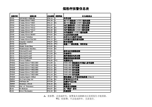
申克故障信息表

A:重报警,会造成停车;报警条在故障解决后需要复位才能消除。
A:重报警,会造成停车;报警条在故障解决后需要复位才能消除。
A:重故障,设备停车;W1:轻故障,但是报警信息需要复位;W2:轻故障,报警信息随报警消失而消失;IG:忽略此故障。
A:重报警,会造成停车;报警条在故障解决后需要复位才能消除。
A:重报警,会造成停车;报警条在故障解决后需要复位才能消除。
A:重报警,会造成停车;报警条在故障解决后需要复位才能消除。
消失而消失;IG:忽略此故障。
A:重报警,会造成停车;报警条在故障解决后需要复位才能消除。
厨 Ла布斯液压克勒斯瓦亚加菲阿说明书
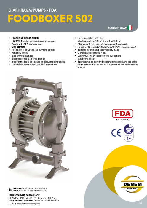
Intake/delivery connections:CLAMP / DIN / GAS 2” f (*) - flow rate 650 l/min STANDARD: II 3/3 GD c IIB T135°C (zone 2)CONDUCT : II 2/2 GD c IIB T135°C (zone 1)STANDARD: II 3/3 GD c IIB T135°C (zone 2) CONDUCT: II 2/2 GD c IIB T135°C (zone 1)* The curves and performance values refer to pumps with submerged suction and a free delivery outletwith water at 20°C, and vary according to the construction material. ** Attention: the average values of the various configurations of materials by ball and ball seats. *** The value depends on the configuration of the pump.Air supply pressure (bar)Guaranteed head/flow rate according to ISO 9906Air consumption NI/minHead(m)U.S. g.p.m.Flow rate (litres/min)Intake/delivery connections CLAMP / DIN / G 2” f (*)Air connection G 1/2” fMax. flow rate*650 l/minMax. air supply pressure8 barMax. head*80 mMax. self-priming capacity** 5 mMax. stored neg. suction9,5Max. diameter of passing solids8 mmNoise***80 dBDisplacement per cycle 1.825 ccvMax. viscosity50.000 cps(*) NPT connections on requestHeadm)H(ft)Q (U.S. g.p.m.)12007862400102030405060708032,865,698,4131,2164,0196,8229,6262,4 079,266,052,839,626,413,21.534,567,69,1H(ft)FOODBOXER 502: A2-M3M3AISI 316Packing: cardboard box - 79 x 55 x 52 cm-weight 25 KgFB502AISI 316FB502AISI 316STANDARD: II 3/3 GD c IIB T135°C (zone 2)CONDUCT : II 2/2 GD c IIB T135°C (zone 1)FOODBOXER COMPOSITION CODEPRODUCT APPLICATION*) Cover diaphragms (only on Hytrel diaphragms) cannot be fitted individually.ex. FB502-A-HTAAT--Foodboxer 502, body AISI 316, air side diaphragm Hytrel, fluid side diaphragm PTFE, balls AISI 316, ball seats AISI 316, O-Ring in PTFE。
申克DISOCONT固体流量给料机故障事件表

编号 故障代码 事件级别 英语说明 中文说明 Event Group 1: Calibration (事件组1:标定) 1 CA-01 A Error LC Input 称重传感器故障 2 CA-03 A Error Bin LC Input 仓称重传感器故障 3 CA-05 A Linearization Error 线性化故障 4 CA-06 A Event Tara Corr. 超出调零范围 Event Group 2: Check Measurement (事件组2:在线校正) 5 CH-02 W2 Min. Fill Weight 校正仓重小于下限值 6 CH-03 W2 Max. Fill Weight 校正仓重大于上限值 7 CH-04 W2 Abs. Tare Corr. Error 绝对零点校正超差 8 CH-05 W2 Rel. Tare Corr. Error 相对零点校正超差 9 CH-06 W2 Abs. Range Corr. Error 绝对量程校正超差 10 CH-07 W2 Rel. Rang Corr. Error 相对量程校正超差 11 CH-08 W2 Feeder Not Stopped 给料机未停止 12 CH-09 W2 No Check Release 无在线校正释放信号 13 CH-10 W2 Prepare Check Meas. 准备在线校正测量 14 CH-11 W2 Expect Acceptance 等待接受校正结果 Event Group 3: Controller (事件组3:控制器故障) 15 CO-01 W2 Controller Limited 控制幅值=20mA 16 CO-02 W2 Err. MIN Flow Gate 流量阀全关 17 CO-03 W2 Err. MAX Flow Gate 流量阀全开 Event Group 4: MAX (事件组4:上限值故障) 18 HI-01 W2 LC Input > MAX 称重传感器超量程 19 HI-02 W2 I > MAX 流量大于上限值 20 HI-05 W2 Deviation > MAX 控制偏差超差 21 HI-09 W2 Load > MAX 测量载荷大于上限值 22 HI-10 W2 Bin LC Input > MAX 仓称重传感器大于上限值 23 HI-11 W2 Err. Bin Level MAX 仓重大于上限值 Event Group 5: Interlocking (事件组5:联锁故障) 24 IL-01 W2 No Release 无释放信号 25 IL-02 W2 Error Mechanics 1 机械故障1 26 IL-03 W2 Error Electricity 电气故障 27 IL-04 W2 Error Mechanics 2 机械故障2 28 IL-05 W2 Not Ready 未准备就绪 29 IL-06 W2 Not Ready for Start 未准备好起动 Event Group 6: MIN (事件组6:下限值故障) 30 LO-01 W2 Error LC Input < MIN 称重传感器受力小于下限值 31 LO-02 W2 Error I-Min 流量小于下限值 32 LO-11 W2 Error Bin Level MIN 仓重小于下限值 Event Group 7: Sequence Monitoring (事件组7:控制过程故障) 33 SC-01 W2 Setpoint Limited 设定值大于上限值 34 SC-02 W2 Stand-By 设定值小于下限值
乐泰C5-A铜基抗咬合剂
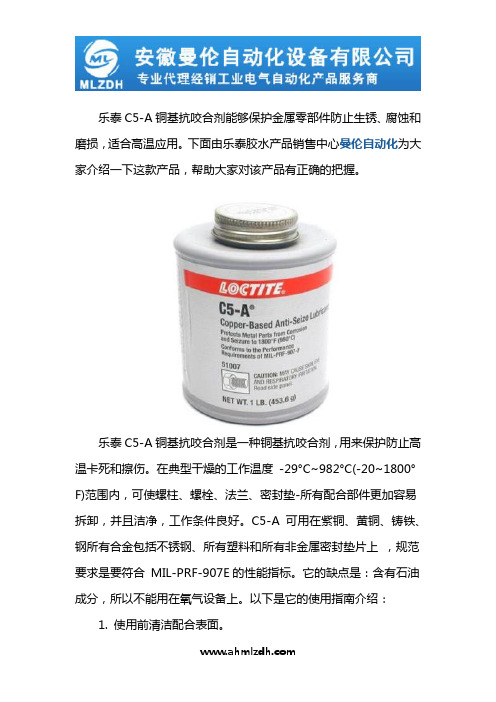
乐泰C5-A铜基抗咬合剂能够保护金属零部件防止生锈、腐蚀和磨损,适合高温应用。
下面由乐泰胶水产品销售中心曼伦自动化为大家介绍一下这款产品,帮助大家对该产品有正确的把握。
乐泰C5-A铜基抗咬合剂是一种铜基抗咬合剂,用来保护防止高温卡死和擦伤。
在典型干燥的工作温度-29°C~982°C(-20~1800°F)范围内,可使螺柱、螺栓、法兰、密封垫-所有配合部件更加容易拆卸,并且洁净,工作条件良好。
C5-A 可用在紫铜、黄铜、铸铁、钢所有合金包括不锈钢、所有塑料和所有非金属密封垫片上,规范要求是要符合MIL-PRF-907E的性能指标。
它的缺点是:含有石油成分,所以不能用在氧气设备上。
以下是它的使用指南介绍:1. 使用前清洁配合表面。
2. 注意:在研磨或用钢丝刷清洁表面时请戴防尘面具。
从螺纹上清洁下来的灰尘可能含有金属成份,吸入会造成肺部伤害或其他伤害,在螺纹和端头或螺母和螺栓表面上薄薄地涂一层,合拢装配。
乐泰C5-A铜基抗咬合剂的基本参数如下:颜色:铜红色;固体润滑成分:铜/石墨;温度范围:-29℃至982℃;包装规格:453.6g/罐;乐泰C5-A铜基抗咬合润滑剂;该产品在高性能特重润滑中含有铜和石墨。
安徽曼伦自动化设备有限公司是一家专业代理经销品牌工业电气自动化产品服务商,集科工贸于一体的系统集成商,公司代理汉高旗下经营汉高旗下乐泰Loctite、泰罗松teroson等厌氧胶、快干胶、聚氨酯、硅橡胶等粘合剂。
同时,该公司广泛服务于汽车、电力、电子、冶金、化工、太阳能、水泥、造纸、船舶、卷烟、纺织、机床、包装机械、印刷机械、橡胶机械、物流设备等行业,以货期快,服务好,价格优惠等优势赢得了广大客户的支持与信任。
如果您想进一步了解,可以直接点击官网曼伦自动化进行在线咨询。
07-Conformationaa_Anal-04[1]
![07-Conformationaa_Anal-04[1]](https://img.taocdn.com/s3/m/0631236ea98271fe910ef947.png)
ΔG = +3 kcal mol-1
Conformational Preferences: Acetaldehyde
staggered
Torsional Strain (Pitzer Strain): Ethane
eclipsed
A H O C H
H H
H O C H H H B
H CH2 C H H H H CH2 H
+2.0 kcal/mol
eclipsed conformation H
C H
Conformational Preferences 1-Butene (X = CH2); Propanal (X = O)
H
Wiberg K. B.; Martin, E. J. Amer. Chem. Soc. 1985, 107, 5035-5041.
Relevant Orbital Interactions:
H
Chem 206
Torsional Strain: the resistance to rotation about a bond Torsional energy: the energy required to obtain rotation about a bond Torsional Angle: also known as dihedral angle Torsional steering: Stereoselectivity originating from transition state torsional energy considerations
A
H Me X
A' C
H X
C
H X
C
耶格尔计量型清洗装置安装、操作和维护手册说明书
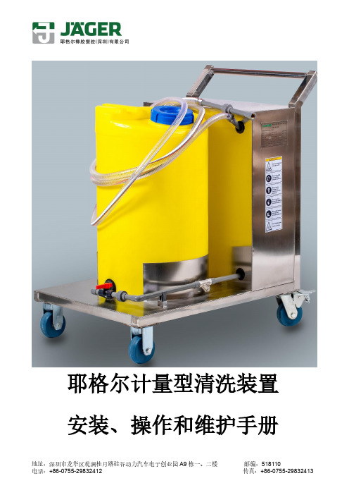
耶格尔计量型清洗装置安装、操作和维护手册地址:深圳市龙华区观澜桂月路硅谷动力汽车电子创业园A9栋一、二楼邮编:5181101.简介本手册内容仅适应于耶格尔计量型清洗装置,在计量型清洗装置运输、安装和操作过程中应严格遵守本手册,并保证本手册与计量型清洗装置一起保管。
2.基本原理和应用耶格尔计量型清洗装置采用甲酸(HCOOH)来清洗污水厂使用的膜片式曝气器,其主要原理是:甲酸混合空气到达曝气器内部,与膜片孔内和膜片表面的沉积物(碳酸盐或其他沉积物)反应,使沉积物溶解,达到清洗效果。
3.安全守则在使用本清洗系统之前,应该认真阅读本手册中关于安全方面的注意事项,同时也应该严格遵守当地的安全条例。
在未得到耶格尔公司的书面承诺之前,请勿使用本计量型清洗装置用于其它目的,否则客户应自行承担因此产生的相关后果。
如有不明,请向耶格尔咨询。
甲酸药剂的使用应该严格遵守相关的安全条款。
4.质保期我公司对本计量型清洗装置进行质量保证,质保期为出货之日起12个月,非正常使用对计量型清洗装置造成的损坏不在质保范围。
如有疑问,请与您的销售代表联系。
5.耶格尔计量型清洗装置构成耶格尔计量型清洗装置包括一个KD计量式隔膜泵,一条5米的分液软管,一个电控箱、3个球阀、快速接头、容积100L的PP储酸桶、手推车。
基本原理是:KD计量式隔膜泵把甲酸从储液桶里抽出来,然后通过分液软管到达快速接头,然后通过快速接头喷射到空气立管中,随压缩空气到达曝气器内部和膜片表面,达到清洗效果。
电控箱外接220V/380V的电源(根据铭牌标识区分)让隔膜泵正常运转,所有设备被固定在一个小车上以便于移动。
计量型清洗装置的具体组成部件如下:1)酸洗小车一辆;2)PP储酸桶(带刻度,100L,颜色黄色或白色);3)含电动机的KD系列计量式隔膜泵(所有的接液部分都是耐化学腐蚀的);4)PVC分液软管软管长5米(一端与隔膜泵输出端UPVC硬管连接,另一端与螺纹式快速接头连接);5)SS304Y型过滤器(用于过滤进入隔膜泵的甲酸溶液中的杂质,防止杂质损伤隔膜泵);6)球阀(有UPVC/SS304/SS316材质);7)快速内螺纹接头1个,通过不锈钢卡箍接在分液软管上;8)快速外螺纹酸洗接头,每单元1个,与计量型清洗装置上的快速内螺纹接头连接;9)电控箱1个,有2个按钮,绿色为开启,红色为停止;10)电缆线和220V插头;11)润滑油0.5L—隔膜泵用(出厂时隔膜泵内已充满,根据需要可另行购买添加,规格参考隔膜泵说明书);12)甲酸溶液(此项属计量型清洗装置运行所必须,由于安全运输和存储原因,不包含在厂家的标准供货列表中,客户在使用前需自行在当地购买);13) 计量型清洗装置内部流程如下:可清洗回流快速接头空气管网进入曝气器清洗系统流程图计量型清洗装置实物如下图(供货实物与此图可能存在差异)计量型清洗装置实物图(出售小车与此图可能存在差异)6.化学药剂耶格尔计量型清洗装置的清洗溶液一般采用85%的甲酸溶液,它可以溶解掉大多数沉淀物。
美国麦克尼安机械与工具公司产品维修部件手册说明书

3655-251-0003/2011Please read and save this Repair Parts Manual. Read this manual and the General Operating Instructions carefully before attempting to assemble,install, operate or maintain the product described. Protect yourself and others by observing all safety information. The Safety Instructions are contained in the General Operating Instructions. Failure to comply with the safety instructions accompanying this product could result in personal injury and/or property damage! Retain instructions for future reference . AMT reserves the right to discontinue any model or change specifications at any time without incurring any obligation.©2006 American Machine & Tool Co., Inc. of PA, A Subsidiary of The Gorman-Rupp Company, All Rights Reserved.Periodic m aintenance and inspection is required on all pum ps to insure proper operation. Unit m ust be clear of debris and sedim ent. Inspect for leaks and loose bolts. Failure to do so voids warranty.SELF-PRIMING SPRINKLER/BOOSTER PUMPSRefer to pump manual 1808-634-00for General Operating and Safety Instructions.DescriptionThese self-priming (to 20 ft. lift) lawnsprinkler pumps are equipped with a check valve to assist in positive priming, a high performance closed impeller, a Buna-N mechanical seal to prevent leakage, and a continuous duty motor.Pumps are designed for higher pressure applications such as lawn sprinkling,spraying irrigation, also draining andgeneral de-watering applications. Casing working pressure to 150 psi (1034 kPa).Handles fluids from 40º to 180º F (4º to 82ºC). For use with nonflammable, non-abrasive liquids compatible with pump component materials.MaintenanceMake certain that this unit isdisconnected frompower source before attempting to service or remove any component!MECHANICAL SEAL REPLACEMENT Refer to Seal Replacement figures 2, 3. IMPORTANT: Always replace both seal seat (Ref. No. 6) and seal head (Ref. No. 7)to insure proper mating of components!Also, impeller seal (Ref. No. 22) (where applicable) should be replaced anytime impeller fastener (Ref. No. 23) has been removed.1.Unthread fasteners (Ref. No. 16) and remove pump casing (Ref. No. 14),casing seal (Ref. No. 5), and flapper valve (Ref. No. 13) from adapter (Ref.No. 4).2.Unthread fasteners (Ref. Nos. 12 and 17) and remove volute (Ref. No. 10)from adapter.3.Remove impeller fastener, impeller seal (where applicable), and impeller (Ref. No. 9).4.Shaft sleeve (Ref. No. 21) (where applicable) and seal head can now be pulled from shaft.IMPORTANT: Care should be taken to insure that the same number of shim washers (Ref. No. 8) are replaced behind impeller as were removed. These shim washers are located directly behindimpeller. These washers as well as impeller key (Ref. No. 24) (where applicable)become loose as impeller is removed.NOTE: Some motors (Ref. No. 20) use an open end 7/16" wrench across flats on rear of motor shaft (remove bearing cap foraccess) to prevent shaft from turning. Othermotor shafts have a screwdriver slot instead of flats.5.Unscrew fasteners (Ref. No. 23). Remove mounting base and handle (Ref. No. 18 &2) (where applicable), and adapter from motor mounting face.6.Push seal seat from back of adapter recess with a screwdriver.7.Clean adapter recess before inserting a new seal seat.The precision lapped faces on mechanical seal are easily damaged.Handle your replacement seal carefully.8.Carefully wipe polished surface of new seal seat with a clean cloth.9.Wet rubber portion of seal seat with a light coating of soapy water.10.Press new seal seat squarely into recessin adapter. If seal seat does not press squarely into cavity, it can be adjusted in place by pushing on it with a piece of pipe. Always use a piece of cardboard between pipe and seal seat to avoid scratching polished surface.11.After seal seat is in place, ensure that it isclean and has not been marred.NOTE: If removed, slide slinger washer (Ref.No. 1) onto shaft until it is located approxi-mately 1/8" from face of motor bearing hub.ing a clean cloth, wipe shaft/shaftsleeve and make certain that it is perfectly clean.13.Secure foot and handle (where applicable)and adapter on motor mounting face.Carefully guide motor shaft through seal seat.14.Replace shaft sleeve and impeller key(where applicable).IMPORTANT: Before installing new shaftsleeve, apply a bead of non-hardening, pliable sealant (such as Permatex® Form-A-Gasket®No. 2) to motor shaft shoulder.15.Wet inside rubber portion of new seal headwith a light coating of soapy water. Slide head onto shaft/shaft sleeve. Seal head and seal seat will meet. Reinstall any shims which have been removed. (See Shim Adjustment).16.Install impeller and reassemble pump.17. A short "run-in" period may be necessaryto provide completely leak-free seal operation.SHIM ADJUSTMENT (365 SERIES ONLY)When installing a replacement impeller (Ref.No. 9) or motor (Ref. No. 20), it may benecessary to adjust number of shims (Ref. No.8) to insure proper running clearance between impeller and volute (Ref. No. 10). Proceed as follows:NOTE: A proper running clearance is less than 0.010" (face of impeller to mating face of volute).1.For impeller replacement, add one (0.010")shim in addition to those removed originally.2.For motor replacement, add two (0.010")shims in addition to those removed during disassembly.3.Reassemble the pump as described in steps 16 and 17 (above).IMPORTANT: Ensure that volute is snugly in place and check shaft to make sure it is turning freely (use 7/16" wrench or screwdriver to turn shaft). If it turns freely, check to ensure that adapter (Ref. No. 4) and volute are fitted metal-to-metal where they meet on outside. If they are not metal-to-metal, tighten fasteners (Ref. No.12 & 17) and recheck shaft for free turning.Tighten carefully, turning shaft while tightening so that motor bearings are not damaged in the event that too many shims were installed. If shaft seizes before fasteners are completelytight, disassemble pump and remove one (0.010") shim and repeat reassembly.4.When proper clearance is obtained,reassemble.3655-95 thru 3657-95 and S pecifications Information and Repair Parts Manual 3790-95 thru379L-95 Please provide following information:-Model number-Serial number (if any)-Part descriptions and number as shown in parts listRepair Parts List3790 (3/4 HP)3791 (1 HP)3792 (1½ HP)3793 (2 HP)379G (3/4 HP)379H (1 HP)3797 (1½ HP)379K (2 HP)379A (1 HP)379B (1½ HP)379C (2 HP)379D (3 HP)3657 (5 HP)Description379F (1 HP)379J (1½ HP)379E (2 HP)379L (3 HP)3655 (5 HP)3656 (7½ HP)Qty.1Slinger washer1534-000-001534-000-001534-000-001534-000-001470-093-001470-093-001 2Handle1515-000-001515-000-001515-000-001515-000-00 -- -- 1 3Fastener******4 4Adapter1608-011-011608-011-011608-011-011608-011-013655-030-093655-030-091 5Casing Seal - Buna N (std)1610-000-001610-000-001610-000-001610-000-002186-000-002186-000-001 - Viton (opt)1610-001-001610-001-001610-001-001610-001-002186-001-002186-001-006 & 7† Shaft seal assy. -Buna N (std)1640-161-961640-161-961640-161-961640-161-961640-163-901640-163-901† - Viton (opt)1640-161-971640-161-971640-161-971640-161-971640-163-911640-163-91 8Impeller Shim pkg. -- -- -- -- 1664-000-901664-000-901 9Impeller379A-011-09379B-011-09379C-011-09379D-011-093655-012-093656-012-091 10Volute379B-150-09379B-150-09379D-150-09379D-150-093655-150-093655-150-091 11Washer******2 12Fastener******2 13Flapper valve -Buna N (std)1609-002-001609-002-001609-002-001609-002-001609-002-001609-002-001 -Viton (opt)1695-011-901695-011-901695-011-901695-011-901695-011-901695-011-90 14Casing2111-001-012111-001-012111-001-012111-001-012112-001-022112-001-021 15Pipe plug******2 16Fastener******4 17Fastener******1 18Foot1506-000-001506-000-001506-000-001506-000-00 -- -- 1 19Fastener******1 20Motor - 1 Phase ODP1626-010-001626-011-001626-012-001626-024-00 -- --1 - 3 Phase ODP1626-014-001626-015-001626-016-001626-025-00 -- --- 1 Phase TEFC1626-069-001626-050-001626-070-001626-071-001626-078-00 --- 3 Phase TEFC1626-077-001626-053-001626-054-001626-072-001626-044-001626-045-00 21Shaft sleeve -- -- -- -- 1472-000-001472-000-001 22Impeller seal -- -- -- -- 1471-020-001471-020-001 23Impeller fastener1784-001-091784-001-001784-001-001784-001-001756-000-001756-000-001 24Impeller key -- -- -- -- 1471-030-001471-030-001 (*)Standard hardware item, available locally(†)Seal head (Ref. No. 7) and seat (Ref. No. 6) available as a set only. When replacing a shaft seal assembly, a new impeller seal (Ref. No. 23) should also be used. (Model series 365 only).-2-。
美国Chcontech传感器
美国Chcontech传感器美国Chcontech传感器广州南创陈工供应Chcontech 美国ChcontechCR40601不锈钢 1,2.2,4.7,10,15,22,33,47,68,100,150,220,330,470T可代替德国HBM的RTN轮辐扭环式传感器Chcontech 美国ChcontechCF6040632不锈钢 1,2,5,10,20,50,100,200T可代替德国HBM的C2轮辐式传感器Chcontech 美国ChcontechCFM6040632合金钢 1,2,5,10,20,50,100,200T可代替德国HBM的C2轮辐式传感器Chcontech 美国ChcontechCWD30801不锈钢 20,30,40,60T可代替德国HBM的C16IC3数字传感器Chcontech 美国ChcontechCWM30801合金钢 20,30,40,60T可代替德国HBM的C16IC3数字传感器Chcontech 美国ChcontechCW70304悬臂梁不锈钢 0.22,0.55,1.1,1.76,2,2.2,4.4,10T可代替德国HBM的HLC悬臂梁传感器Chcontech 美国ChcontechCWM70304悬臂梁合金钢 0.22,0.55,1.1,1.76,2,2.2,4.4,10T可代替德国HBM的HLC悬臂梁传器Chcontech 美国ChcontechCF604013S型合金钢 0.1,0.2,0.3,0.5,0.75,1,2,3,10T 可代替传力BSS系列)Chcontech 美国ChcontechCW90101不锈钢20,30,40,60,100,200T可代替德国HBM的C16A柱式传感器Chcontech 美国ChcontechCWM90101合金钢 20,30,40,60T可代替德国HBM的C16A柱式传感器Chcontech 美国ChcontechCW703031不锈钢 5,10,20,50,100,200,500,1000KG可代替德国HBM的Z6FD1/Z6FC3波纹管传感器Chcontech 美国ChcontechCF604011合金钢 0.1,0.2,0.3,0.5,0.75,1,2,3,5T可代替托利多的TSC的S型式传感器Chcontech 美国ChcontechCW80201不锈钢 20,30,40,50T可代替托利多的SBD桥式传感器CWM80201合金钢 20,30,40,50T可代替托利多的SBD桥式传感器Chcontech 美国ChcontechCW90102不锈钢 20,30,50,100,200,300T可代替托利多的GD柱式传感器Chcontech 美国ChcontechCW90102B合金钢 20,30,50,100,200,300T可代替托利多的GD柱式传感器Chcontech 美国ChcontechCW90103不锈钢 0.5-2,20,30,50,100,200,300T可代替德国赛多利斯PR6021柱式传感器Chcontech 美国ChcontechCW90103B合金钢 0.5-2,20,30,50,100,200,300T可代替德国赛多利斯PR6021柱式传感器CW703032不锈钢 10,20,50,100,200,500KG可代替美国TEDEA的355波纹管传感器CWM703032合金钢 10,20,50,100,200,500KG可代替美国TEDEA的355波纹管传感器CF6040602不锈钢 0.05,0.1,0.2,0.5,1,2T微型拉压测力传感器Chcontech 美国ChcontechCFM6040602合金钢 0.05,0.1,0.2,0.5,1,2T微型拉压测力传感器Chcontech 美国ChcontechCWD30802数字传感器 20,30,40,50T CWM80201数字传感器 20,30,40,50TChcontech 美国ChcontechCWM703031合金钢5,10,20,50,100,200,500KG 可代替德国HBM的Z6FD1/Z6FC3波纹管传感器Chcontech 美国ChcontechCRM40601合金钢 1,2.2,4.7,10,15,22,33T可代替德国HBM 的RTN轮辐扭环式传感器Chcontech 美国ChcontechCW80207桥式合金钢 3,5,7.5,10,15,20,30,50,60T桥式称重传感器CF406033 0.05,0.1,0.2,0.5,1,2,5,10,20TCF406081 0.3,0.5,1,1.2,5,10,25,50,100T可代替Interface的1200系列CF60405 20,30,50,75,100,150,200,250,300,500,700KG,1,1.5,2,3,5,7.5,10T美国Chcontech传感器美国Chcontech传感器以上内容技术参数以《OIML60号国际建议》92年版为基础,最新具体变化可查看《JJG669—12 美国Chcontech广州南创传感器事业部检定规程》。
申克故障信息表
A:重报警,会造成停车;报警条在故障解决后需要复位才能消除。
A:重报警,会造成停车;报警条在故障解决后需要复位才能消除。
A:重故障,设备停车;W1:轻故障,但是报警信息需要复位;W2:轻故障,报警信息随报警消失而消失;IG:忽略此故障。
A:重报警,会造成停车;报警条在故障解决后需要复位才能消除。
A:重报警,会造成停车;报警条在故障解决后需要复位才能消除。
A:重报警,会造成停车;报警条在故障解决后需要复位才能消除。
消失而消失;IG:忽略此故障。
A:重报警,会造成停车;报警条在故障解决后需要复位才能消除。
F3型发动机零件目录图册说明书

零件目录图册
PARTS CATALOGUE
F3型发动机
Workmate Engine Manual
Workmate Engine Manual
▲▲
▲▲
▲
▲
编制说明 本册为F3发动机零部件目录图册,零部件目录图册是根据摩托车的安装配置顺序进行编辑,用于客户订购零件时参考。 欲知某零件的名称、件号或装配关系,可按零件形状,在有关的插图中查找,即可知名称、数量、状态、是否维修(“Y”为是,“N”为否)、重 量、属性(零件材质):Metal-金属(合金钢)、Aluminium-铝、Rubber-橡胶、Plastic-塑料、Asbestos-石棉、备注(该零件安装的位置或其他)。 索引由件号和图号组成,件号按照A、B、C、D……顺序排列。根据件号可查找其图号。 温馨提示:此图册中的图形仅供参考,一切以实物为准。如有零件变动,不另行通知。
Compilation This book for the F3Atlas engine parts catalog Atlas, spare parts inventory atlas is based on motorcycles in order to edit the installation conguration for the customer order parts reference. For a parts name, parts number or assembly relationship, according to part shape, in the illustrations in the search, you can know the name, number, status, whether the maintenance ( "Y" is yes, "N" for no), weight , property (part material): Metal-metal (alloy steel), Aluminium-Aluminum, Rubber-Rubber, Plastic-Plastic, Asbestosasbestos, Notes (the parts installed location or other). Index numbers and drawing numbers from the pieces of the composition, piece number in accordance with A, B, C, D ... ... order. According to its plan to nd pieces of ID numbers can be. Warm Tip: The graphics in this atlas for reference only, and all kind prevail. If spare parts to change without ▲
时光剃刀 MX 5075 骑行裁缸喷头 模型号 75755 和 75755T 零件目录说明书
Register at .Original Instructions(EN)*3433-629*AOrdering Replacement PartsTo order replacement parts,please supply the part number, the quantity,and the description of each part desired. Understanding Reference NumbersEach identified part in an illustration has a reference number.The reference number for a part also appears in the parts list,along with other information about the part. This catalog uses two special reference number formats, one to indicate parts in a service assembly and another to indicate the quantity of a given part in an illustration. Service Assembly Reference NumbersParts in service assemblies have reference numbers in the form a:b.The a represents the reference number of the entire service assembly and the b represents a sequential number unique to each part within the service assembly.For example,a wheel assembly might be identified byreference number6,the tire by6:1,the valve by6:2,and the wheel by6:3.When you order the assembly identified by reference number6,you receive all parts identified by reference numbers6:1,6:2,and6:3.However,you may also order any part individually.Reference numbers of this type appear in illustration and in parts lists.Reference Numbers Indicating QuantityIn an illustration,if a reference number indicates more than one part,the reference number has the form nX y.The n represents the quantity of the part,the X is the multiplication symbol,and the y represents the reference number.For example,in an illustration,the reference number2X37 means that two of the parts identified by reference number 37are indicated.2ContentsFrame Assembly (4)Deck Lift Assembly (6)Tire and Caster Assembly (8)Traction Drive Assembly (10)LH Transaxle Assembly No.139-7460 (12)RH Transaxle Assembly No.139-7461 (14)Brake Assembly (16)Rear Tire Assembly (18)Motion Control Assembly (20)Engine and Muffler Assembly (22)Fuel System Assembly with Non-Canister Style Air Filter (24)Carburetor Assembly (26)Air Intake and Filtration Assembly (28)Ignition and Cooling Fan (30)Crankcase and Crankshaft Assembly (32)Governor Control Assembly (34)Piston and Cylinder Head Assembly (36)Blower Housing Assembly (38)Gasket and Seal Kit (40)Body Styling and Fuel Pod Assembly (42)Electrical Assembly (44)50Inch Deck Assembly (46)Frame Decal Assembly (48)Seat Pan Assembly (50)Seat Assembly No.140-5044 (52)Clutch Assembly (54)Attachments and Accessories (56)©2019—The Toro®Company8111Lyndale Avenue SouthBloomington,MN554203Contact us at .Printed in the USA.All Rights ReservedFrame Assembly3433-629A4A0Frame Assembly(continued)Ref.Part Number Qty.Description1137-9820-011Frame Assembly3138-7520-011Plate-Mount,Hydro4139-2352-011Plate-Mount Hydro,RH 5137-7020-011Mount-Hydro,Front(Right) 6139-3211-011Mount-Hydro,Front(Left) 7138-2527-011Brace-Cross,Lower8139-3260-011Bracket-Mount Damper,Lower9138-0867-031Guard-Muffler12138-9820-031Guard-Engine14138-7596-011Footrest15140-20972Axle Stub ASM15:2109-36782Bearing-Ball17138-72002Cap-GreaseRef.Part Number Qty.Description18117-1232-031Bracket-Hitch19138-75162Guard-Rail20139-58901Decal-Timecutter21139-23871Decal-Timecutter22121-29892Decal-Bypass23137-48032Bumper-Rubber24140-34602Bumper-Rubber26138-975320Screw27139-24294Screw-HHF283234-2914Screw-HHF30139-24284Screw-HWH3146-80914Screw-HWH32139-24304Nut-HF,NI33104-830016Nut-HF,NI53433-629ADeck Lift Assembly3433-629A6B0Deck Lift Assembly(continued)Ref.Part Number Qty.Description1137-7093-031Deck Lift ASM2138-60212Bracket-Pivot,Decklift 3137-98441LH Arm ASM4137-98461RH Arm ASM5139-2350-011Bracket-HOC6138-25642Plate-Adjustment,HOC 7137-7087-031Lever-Lift8138-60501Rod-Mount,Deck 9119-88101Pin-Pivot10138-2549-031Pedal-Lift11137-70861Plate-Footlift12140-2746-031Link ASM13140-34612Spacer141-8060057Pin-Cotter15138-97535ScrewRef.Part Number Qty.Description18137-98474Screw-Shoulder2093-88063Washer-Hardened213256-267Washer-Flat2263-22902Washer-Thrust23104-83002Nut-HF,NI24104-83015Nut-HF,NI253296-191Nut-Hex26139-23921Decal-HOC271-6332681Grip-Lever30120-22731Washer-Nylon31139-74521Pedal-Foot Lift32140-20931Spacer33139-25901Screw-CARR343230-32Screw-CARR35139-25971Screw-HHF73433-629ATire and Caster Assembly3433-629A8D0Tire and Caster Assembly(continued)Ref.Part Number Qty.Description 1138-9839-012Fork ASM 2139-58432Tire ASM2:1138-75531Tire2:3232-271Stem-Valve2:4114-16402Bushing-Flange 2:5302-51Fitting-GreaseRef.Part Number Qty.Description5138-98032Spacer-Spanner6325-372Screw-HH73296-452Nut-Hex83256-682Washer-Flat93234-472Screw-HHF93433-629ATraction Drive Assembly3433-629A10E0Traction Drive Assembly(continued)Ref.Part Number Qty.Description1139-74601LH Hydro Transaxle ASM 2139-74611RH Hydro Transaxle ASM 3138-2571-031Crossplate-Hydro4139-23991V-Belt5138-98091Spacer6138-72761Arm-Idler7138-72771Spacer-Arm,Idler868-00301Idler9138-75971Pulley-Idler,Flat10137-70401Spring-Return,Pedal 11138-72451Rod-Bypass,RH12138-72431Rod-Bypass,LH133290-3072Pin-Cotter Ref.Part Number Qty.Description 143230-81Screw-CARR 15115-17941Screw-HHF 16138-75904Screw-HHF 17322-114Screw-HH 18324-82Screw-HH 19324-104Screw-HH 215-44601Washer-Pivot 22104-830010Nut-HF,NI 243296-486Nut-Hex 25242-508Nut-Lug 323256-256Washer-Flat 333256-232Washer-Plain 34119-89522WasherLH Transaxle Assembly No.139-7460LH Transaxle Assembly No.139-7460(continued)Ref.Part Number Qty.Description1106-86951Main Housing ASM 2106-86961Side ASM4110-85611Pump Block ASM6103-26661Cylinder Block Kit7104-21891Plug-Thread,Straight 9104-530516Screw-HHF14106-86771Ring-Retaining,External 15106-86781Rod-Bypass16106-86791Ring-Retaining,Internal 19104-53041Swashplate-Trunnion 21104-21161Stud22112-98531Puck-Friction2794-19361Spring-Block28120-55381Washer29104-53061Shaft-Input30104-53111Bearing-Ball31104-53071Ring-Retaining32104-53081Spacer33104-53101Seal-Lip34104-53092Ring-Retaining3594-69222Bearing-Thrust36104-53391Washer-Flat37104-53401Ring-Retaining38104-53161Gear-Pinnion,13T 39106-86831Shaft-Motor40104-53601Washer41119-55412Washer42104-53171Gear-10T/48T Ref.Part Number Qty.Description43104-53181Gear-Jackshaft,10T 44104-53291Pin-Jackshaft45112-98541Ring-Spiral,Retaining 46112-98551Gear-52T,Bull47112-98561Washer48112-98571Bearing-Sleeve49120-71041Shaft-Axle50112-98591Bushing-Axle51112-98601Seal-Lip52106-86861Seal Kit53106-86971Expansion Plate Kit 54135-73491Fan And Pulley Kit 54:1116-97141Nut-HJ54:2116-97081Washer-Slotted54:4135-73641Fan7.0X10Blade 55106-86881Brake Arm Kit57112-98611Center Section Filter Kit 58104-21471Sealant59120-55491Bypass Kit61114-16341Filter Kit98120-71091Tube-Axle100106-86941Disc-Brake,Cog 101115-50571Cover-Nut,Axle 124109-59391Hub Kit138112-98661Breather Kit139114-16351Breather ASM200117-53621Control Arm Kit 209114-84671Puller-Hub,4BoltRH Transaxle Assembly No.139-7461RH Transaxle Assembly No.139-7461(continued)Ref.Part Number Qty.Description1106-86741Main Housing ASM 2106-86751Side ASM4110-85611Pump Block ASM6103-26661Cylinder Block Kit7104-21891Plug-Thread,Straight 9104-530516Screw-HHF14106-86771Ring-Retaining,External 15106-86781Rod-Bypass16106-86791Ring-Retaining,Internal 19104-53041Swashplate-Trunnion 21104-21161Stud22112-98531Puck-Friction2794-19361Spring-Block28120-55381Washer29104-53061Shaft-Input30104-53111Bearing-Ball31104-53071Ring-Retaining32104-53081Spacer33104-53101Seal-Lip34104-53092Ring-Retaining3594-69222Bearing-Thrust36104-53391Washer-Flat37104-53401Ring-Retaining38104-53161Gear-Pinnion,13T 39106-86831Shaft-Motor40104-53601Washer41119-55412Washer42104-53171Gear-10T/48T Ref.Part Number Qty.Description43104-53181Gear-Jackshaft,10T 44104-53291Pin-Jackshaft45112-98541Ring-Spiral,Retaining 46112-98551Gear-52T,Bull47112-98561Washer48112-98571Bearing-Sleeve49120-71041Shaft-Axle50112-98591Bushing-Axle51112-98601Seal-Lip52106-86861Seal Kit53106-86971Expansion Plate Kit 54135-73491Fan And Pulley Kit 54:1116-97141Nut-HJ54:2116-97081Washer-Slotted54:4135-73641Fan7.0X10Blade 55106-86881Brake Arm Kit57112-98621Center Section Filter Kit 58104-21471Sealant59107-24891Bypass Arm Kit61114-16341Filter Kit98120-71091Tube-Axle100106-86941Disc-Brake,Cog 101115-50571Cover-Nut,Axle 124109-59391Hub Kit138112-98661Breather Kit139114-16351Breather ASM200117-53621Control Arm Kit 209114-84671Puller-Hub,4BoltBrake AssemblyBrake Assembly(continued)Ref.Part Number Qty.Description1138-25141Brake Box ASM 2133-9284-031Bracket-Mount,Brake 3138-25911Rod-Brake,LH4138-25921Rod-Brake,RH5117-11694Spring-Compression Ref.Part Number Qty.Description 73290-3072Pin-Cotter 832144-364Screw-PPH 932144-42Screw-HWH 10119-89526Washer 113296-422Nut-Lock,NIRear Tire AssemblyRear Tire Assembly(continued)Ref.Part Number Qty.Description 1139-58472Tire ASM 1:1140-27311Tire Ref.Part Number Qty.Description 1:3232-271Stem-Valve 1:99232-371Tube●●Not illustratedMotion Control AssemblyMotion Control Assembly(continued)Ref.Part Number Qty.Description1138-7598-031Plate-Control Box,LH 2138-7599-031Plate-Control Box,RH 4119-34702Actuator Arm ASM4:2256-1562Bushing-Flange5133-9299-052Arm-Control6139-58032Eccentric7138-75392Spring-Torsion8133-70551Handle-Control,LH8:1121-07261Grip9133-70571Handle-Control,RH 9:1121-07261Grip10138-25802Rod-Hydro,Front 11138-25792Rod-Hydro,Rear 12121-17532Pin-Rod,Hydro13138-97501Speed Control ASM 14138-75412Plate-Retainer15132-93681Knob-RH16132-93691Knob-LH17132-68532Damper-Non Cavitating 18138-72152Stud-DamperRef.Part Number Qty.Description1993-60792Spacer-Nylon20120-22732Washer-Nylon21119-89252Washer-Belleville22119-89522Washer23139-58112Bolt-Pivot,Eccentric24117-11982Bolt-Pivot25120-79502Screw2637-87712Bolt-Shoulder,HF27115-50992Bolt-Pivot2894-44961Screw-PPH2932144-12Screw-Taptite303229-114Screw-CARR31138-975310Screw323234-424Screw-HHF33104-72014Nut-HF343296-426Nut-Lock,NI35117-12402Washer36104-83002Nut-HF,NI37104-83014Nut-HF,NI213433-629AEngine and Muffler Assembly3433-629A22J0Engine and Muffler Assembly(continued)Ref.Part Number Qty.Description 1139-06031Engine-2P77F 2139-58651Muffler 532144-1094Screw-Thd 63256-243Washer-FlatRef.Part Number Qty.Description9121-01994Nut-HH10127-92794Washer-Lock,Split12120-43172Gasket-Exhaust233433-629AFuel System Assemblywith Non-Canister Style Air Filter3433-629A2402Fuel System Assemblywith Non-Canister Style Air Filter(continued)Ref.Part Number Qty.Description 1133-15631Filter-Fuel2120-42516Clamp-Fuel Line 3120-43711Line-Fuel4127-92061Pump-Fuel 5120-42252Screw-HHF 6127-92051Hose-Fuel 7127-92071Hose-Fuel 8127-92302Gasket-Intake 9120-42844Screw-HHF 10127-92441Manifold-Intake Ref.Part Number Qty.Description11127-92454Stud12127-92462Gasket-Carburetor13127-92471Insulator-Carburetor14133-99631Linkage-Throttle15133-99641Spring-Return,Throttle 16127-93551Sleeve-Fuel Line Protector 96136-78401Carburetor Replacement Kit 97127-92901Carburetor Repair Kit 98127-92921Solenoid Kit99136-78371High Altitude Kit●●Not illustrated253433-629ACarburetor Assembly3433-629A2602A1Carburetor Assembly(continued)Ref.Part Number Qty.Description1127-92511Gasket-Carburetor 3127-92462Gasket-Carburetor 14127-93191Spring20127-93251Cover-Shaft,Choke 23127-93281Spring25127-93301Spring28127-93331Clamp-Lock29127-93341Screw-PPH30127-93351SpringRef.Part Number Qty.Description90127-92901Carburetor Repair Kit91127-92921Solenoid Kit92127-93401Float Kit93127-93411Bowl Kit94133-98171Throttle Shaft Kit95136-78441Nozzle And Jet Kit96136-78991Idle Jet Kit97127-93451Choke Shaft Kit273433-629AAir Intake and Filtration Assembly3433-629A2803Air Intake and Filtration Assembly(continued)Ref.Part Number Qty.Description 1127-92351Tube-Breather 2127-92342Clamp-Hose 3136-78061Air Filter Kit 3:1136-78041Prefilter4127-92531Hose-FuelRef.Part Number Qty.Description5127-91871Clamp-Hose6120-42364Nut-Flange7127-90471Manifold-Filter,Air8127-92511Gasket-Carburetor293433-629AIgnition and Cooling Fan3433-629A3004Ignition and Cooling Fan(continued)Ref.Part Number Qty.Description 1127-91974Screw-HWH 2127-91981Screen-Rotating 3127-91994Screw-HWH 4127-92001Fan-Cooling 5127-92011Screw-HWH 6127-92021Washer-Spring 7127-93061Flywheel8127-92104Screw-HSH 9136-78761Alternator 10136-78801Motor-Starter 11127-92081Bracket-LiftRef.Part Number Qty.Description12120-42312Screw-HHF13121-00074Bolt-Flange14136-78832Ignition Coil ASM16127-92204Tie-Zip17136-78791Regulator-Voltage,W/Harness18120-42161Screw-HHF19120-42322Screw-HHF20133-15621Pinion-Starter98133-15661Starter Repair Kit313433-629ACrankcase and Crankshaft Assembly3433-629A3205Crankcase and Crankshaft Assembly(continued)Ref.Part Number Qty.Description 1120-423214Screw-HHF2127-92121Baffle3127-92131Cover-Breather 4127-92141Gasket-Breather 5127-92151Filter-Breather 6120-42161Screw-HHF7127-92171Valve-Breather 8120-42671Seal-Oil10136-78841Adaptor-Filter,Oil 11136-78481Filter-Oil12127-92181Oil Tube ASM 12:1127-92831Dipstick12:2127-92841O-Ring12:4127-92861O-Ring13127-92551Crankshaft13:1120-43201Key-Woodruff 14127-92611Cover-Screen,Oil 15127-92621Screen-Oil 16127-92631Retainer-Screen 17120-42742Pin-Dowel18127-92641Plate-Retainer 19127-92651SpringRef.Part Number Qty.Description20127-92661Valve-Ball21120-42622O-Ring22127-92671Gasket-Cover,Crankcase23133-98051Plug-Drain24133-98061Cover-Crankcase25127-92931Oil Drain Hose ASM26127-92751Fitting-Hose27127-92761Clamp-Hose28127-92711Seal29121-047310Screw-HHF30127-92741Cover-Oil Pump31127-92731O-Ring32127-92721Oil Pump ASM33120-42751Deflector-Oil,Rubber34133-15681Camshaft35136-78821Governor ASM36127-92381Shaft-Governor37120-42582Washer-Plain38120-42571Seal-Oil39120-42561Pin-Hair40120-42322Screw-HHF333433-629AGovernor Control Assembly3433-629A3406Governor Control Assembly(continued)Ref.Part Number Qty.Description1127-92502Clip-Linkage2127-92421Linkage-Choke 3127-92411Spring-Governor 4120-42381Bolt-Arm,Governor 5120-42361Nut-FlangeRef.Part Number Qty.Description6133-99611Arm-Governor7133-99621Spring-Governor8133-15701Control Plate ASM9120-42322Screw-HHF353433-629APiston and Cylinder Head Assembly3433-629A3607Piston and Cylinder Head Assembly(continued)Ref.Part Number Qty.Description1127-92562Connecting Rod ASM 2127-92584Clip-Pin,Piston3127-92572Pin-Piston4127-92592Piston5127-92602Piston Ring Set6127-92244Lifter-Valve7127-92254Rod-Push8127-92262Gasket-Head,Cylinder 9127-92274Pin-Dowel10127-92282Valve Set11133-98021Head-Cylinder,Right 12133-98041Head-Cylinder,Left 13121-04644Stud-Exhaust14120-43172Gasket-Exhaust 15127-92794Washer-Lock,Split 16121-01994Nut-HHRef.Part Number Qty.Description1781-32502Spark Plug18127-92316Screw-HWH19127-92324Screw-HWH20120-43034Seat-Spring,Valve21120-43044Seal-Stem,Valve22120-43054Spring-Valve23120-43064Retainer-Spring,Valve24120-43078Keeper-Valve25127-92332Plate-Guide,Push Rod26136-78814Rocker Arm ASM27127-92952Gasket-Valve Cover28127-90502Cover-Valve29120-42258Screw-HHF30120-42141Screw-Shoulder,HH31136-78911Complete Right Head ASM32136-78921Complete Left Head ASM 373433-629ABlower Housing Assembly3433-629A3808Blower Housing Assembly(continued)Ref.Part Number Qty.Description1133-15714Screw-PPH,Plastic 2127-90451Cover-Fan3127-91966Screw-Shoulder,HWH 4133-15721Shroud-Engine5127-90461Door-Filter,Air6127-92802Pin-Hair7127-92822PinRef.Part Number Qty.Description8127-92811Plate-Spring9136-78771Baffle-Air,Left10120-42102Screw-Shoulder,HHF11136-78781Baffle-Air,Right12127-92871Cleat-Hose13120-42322Screw-HHF393433-629AGasket and Seal Kit3433-629A4009Gasket and Seal Kit(continued)Ref.Part Number Qty.Description1127-92961Gasket And Seal Kit 1:1127-92141Gasket-Breather1:2120-42671Seal-Oil1:3127-92262Gasket-Head,Cylinder 1:4127-92302Gasket-Intake1:5127-92952Gasket-Valve Cover 1:6120-43172Gasket-Exhaust1:7120-42571Seal-Oil Ref.Part Number Qty.Description1:8127-92462Gasket-Carburetor1:9127-92511Gasket-Carburetor1:10120-42622O-Ring1:11127-92671Gasket-Cover,Crankcase 1:12127-92711Seal1:13127-92731O-Ring1:14127-92841O-Ring1:15127-92861O-RingBody Styling and Fuel Pod AssemblyBody Styling and Fuel Pod Assembly(continued)Ref.Part Number Qty.Description1138-9810-031Bracket-Pod2138-6071-031Support-Pod,LH3139-3271-031Support-Tank,Fuel4138-60741Pod-LH5139-24041Pod-RH,Myride6138-60721Fuel Tank ASM6:1139-10911Connector-Elbow,90DEG 6:2117-74001Fitting-Plastic6:346-65602Bushing76098302Spring8137-41191Cap-Fuel,Ratcheting 91070691Clip10139-2380-051Panel-Control11139-23911Decal-Panel,Control 12139-23951Decal-Control Lever,LH Ref.Part Number Qty.Description13139-23941Decal-Control Lever,RH 14139-24031Cable-Throttle15139-24021Cable-Choke16139-23881Decal-Smart Speed 18109-02981Line-Fuel19110-34471Hose-Fuel23117-53991Adaptor-Orifice242412-983Clamp-Hose 256142491Tie-Cable263258-1661Screw-PRH27120-79506Screw28138-97535Screw30139-23971Decal-Adjustment 31120-78931Bumper-GrommetElectrical AssemblyElectrical Assembly(continued)Ref.Part Number Qty.Description1138-25211Harness-Wire1:11093551Fuse-Blade,15Amp 1:21091021Fuse-Blade,25Amp 2105-16921Battery3117-11971Solenoid4137-41001Switch-Ignition563-83601Key-Ignition6103-52211Switch-PTO7110-67652Switch8139-23811Strap-Rubber9140-27131Cable-Battery,Pos 10139-24311Cable-Battery,Red(8Gauge)Ref.Part Number Qty.Description11110-67931Cable-Battery,Black 133256-222Washer-Flat 1432144-42Screw-HWH15321-31Screw-HH163234-141Screw-HHF 173229-11Bolt-CARR 1832128-331Nut-HF1932103-221Nut-Wing203220-22Nut-Jam2133003-001Nut-HF22140-20801Cover-Solenoid 23140-20811Cap-Solenoid 2432180-4181Clip-Harness50Inch Deck Assembly50Inch Deck Assembly(continued)Ref.Part Number Qty.Description1138-9764150Inch Deck And DecalASM1:393-70091Decal-Danger1:4132-08722Decal-Danger,Deck1:599-39431Decal-Routing,Belt1:7112-98401Decal-Scalp,Anti6139-32081Decal-Deck7139-2448-031Baffle-Corner8138-97532Screw9139-32143Spindle ASM9:2120-79352Spacer9:3138-97702Bearing-Ball1032144-4112Screw-Taptite11117-72683Shaft-Spindle12139-74543Pulley133219-63Nut-Hex14115-5059-033Blade-Hi Lift153290-4653Washer-Belleville1626-06713Screw-HH17132-94203Pulley-Idler,Flat 183256-242Washer-Flat19323-94Screw-HH20110-99811Washer-Plain Ref.Part Number Qty.Description2163-74002Washer-Rebound22114-04632Washer-Friction,Composite 23115-49861Spacer24104-83017Nut-HF,NI25138-72621Arm-Idler26119-88201V-Belt27137-20191Rod-Pivot28138-75021Deflector-Discharge29138-72681Spring-Torsion30138-9800-031Baffle-Cutoff313296-591Nut-Lock,NI321-6032993Roller-Scalp,Anti33112-39773Bolt-Shoulder34133-92892Fitting-Washout34:2133-92901O-Ring3532144-44Screw-HWH36138-72661Spring-Return,Hook 37138-72641Spring-Extension38139-58712Pin-Deck39139-32932Cover-Belt4095-32701Connector-Hose41139-3272-032Bracket-Cover,BeltFrame Decal AssemblyFrame Decal Assembly(continued)Ref.Part Number Qty.Description 3136-55971Decal-Engine 4131-10971Decal-Drain,Oil 5131-41571Decal Ref.Part Number Qty.Description 6127-90761Placard-Intake 7132-09041Decal-Shutdown 10140-20991DecalSeat Pan Assembly。
斯姆斯-克林林工业有限公司产品说明书
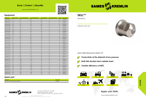
MarketsBond Protect BeautifyEquipmentDesignation Diameter (mm)Flow at 140b (2000 psi)Flow at 200b (2900 psi)Gun filter (MESH)Pattern (cm) at 25 cm Angle Part number SKILL™ TIP 03-070.182102552001635000300307SKILL™ TIP 03-090.182102552002140000300309SKILL™ TIP 03-110.182102552002450000300311SKILL™ TIP 03-130.182102552002955000300313SKILL™ TIP 04-070.233103702001635000300407SKILL™ TIP 04-090.233103702002140000300409SKILL™ TIP 04-110.233103702002450000300411SKILL™ TIP 04-130.233103702002955000300413SKILL™ TIP 06-070.284655601401635000300607SKILL™ TIP 06-090.284655601402140000300609SKILL™ TIP 06-110.284655601402450000300611SKILL™ TIP 06-130.284655601402955000300613SKILL™ TIP 06-150.284655601403570000300615SKILL™ TIP 07-050.35506601401025000300705SKILL™ TIP 07-070.35506601401635000300707SKILL™ TIP 07-090.35506601402140000300709SKILL™ TIP 07-110.35506601402450000300711SKILL™ TIP 07-130.35506601402955000300713SKILL™ TIP 07-150.35506601403570000300715SKILL™ TIP 09-070.336357601401635000300907SKILL™ TIP 09-090.336357601402140000300909SKILL™ TIP 09-110.336357601402450000300911SKILL™ TIP 09-130.336357601402955000300913SKILL™ TIP 09-150.336357601403570000300915SKILL™ TIP 09-170.336357601404080000300917SKILL™ TIP 12-090.3885010151402140000301209SKILL™ TIP 12-110.3885010151402450000301211SKILL™ TIP 12-130.3885010151402955000301213SKILL™ TIP 12-150.3885010151403570000301215SKILL™ TIP 12-170.3885010151404080000301217SKILL™ TIP 14-110.41102012151002450000301411SKILL™ TIP 14-130.41102012151002955000301413SKILL™ TIP 14-150.41102012151003570000301415SKILL™ TIP 14-170.41102012151004080000301417SKILL™ TIP 14-190.41102012151004890000301419SKILL™ TIP 18-130.46134516051002955000301813SKILL™ TIP 18-150.46134516051003570000301815SKILL™ TIP 18-170.46134516051004080000301817SKILL™ TIP 18-190.46134516051004890000301819SKILL™ TIP 20-130.51150017901002955000302013SKILL™ TIP 20-150.51150017901003570000302015SKILL™ TIP 20-170.51150017901004080000302017SKILL™ TIP 20-190.51150017901004890000302019Spare partDesignationPart number PACK OF 10 COLLARS FOR SKILL™ AIRLESS®13498000213 chemin de Malacher - CS 7008638243 MEYLAN Cedex - FRANCEPhone: +33 (0)4 76 41 60 60 - Fax: +33 (0)4 76 41 60 90Airless® is a registered trademark : FR n ° 1 222 301202010 -SKILL™Airless® TipAirless®/Spray TipsHIGH PERFORMANCE SPRAY TIPProductivity of the Airless® at low pressure Built with double hard carbide insert Transfer efficiency of 84%AUTOMOTIVE AGRICULTURAL CONSTRUCTION CONSUMERSINDUSTRIAL TRANSPORTATION WOODApply your SkillsSKILL™Airless® TipWith low pressure Airless® tips, you decrease the pressure by 50% compared to standard tipsmanufacturer. Particularly efficient for water-based UV paint. Recommended use for any quick pro application work with our manual and automatic Airless® range; SFlow™ manual gun and ASI automatic paint sprayers.Technical data tableDesignation Value Unit: metric (US)Operating Pressure 100 (1450)bar/psiDouble Premium Carbide♦SAMES KREMLIN has developed a disruptor tip technology: Skill tips which are able to spray material reacting badly with air inclusion. The new generation of Skill™ tips deliver a softer spray pattern on edges for a perfect overlapping on flat line and facilitates the settings on flat line machines.A double insert tip allows low Airless® atomizing pressure without tail.Our Skill Airless ® tips are made with high quality carbide inserts to provide high abrasion resistance & excellent atomization quality.The Airless ® tips can be used on our SFlow™ manual gun, ASI automatic gun, and all the Airless®gun on the market.Bond Protect Beautify TechnologiesPerformance♦Transfer efficiency of 84%♦Optimum quality of spraying starting from 85 bar♦Light weight with our SFlow spraying gun for maximumcomfortProductivity♦All tips have the same consistent pattern and flow toguarantee constant productivity♦Improved fan width to optimize the number of guns on the line ♦Always clean in production for high productivity with excellentatomizationSustainability♦The carbide used is the hardest in the world to guarantee thelongest lifetime possible.♦Reduced internal volume to avoid dead zone and tipblockage♦Special tip shape to reduce the risk of dirt on the top of thenozzle and facilitate cleaning♦Easy maintenance:The tip is built with a removable lowerinsert to facilitate disassembling and cleaningDescriptionAirless® spray technology Skill Tip。
科学实验用品:科学家实验室迪芬菲斯 物理学实验用品 物理学实验用品说明书
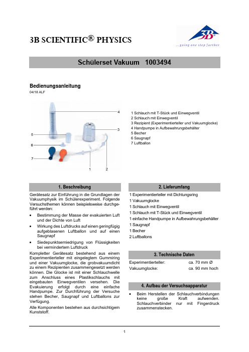
3B SCIENTIFIC ® PHYSICS1Bedienungsanleitung04/18 ALF1 Schlauch mit T-Stück und Einwegventil2 Schlauch mit Einwegventil3 Rezipient (Experimentierteller und Vakuumglocke)4 Handpumpe in Aufbewahrungsbehälter5 Becher6 Saugnapf7 LuftballonGerätesatz zur Einführung in die Grundlagen der Vakuumphysik im Schülerexperiment. Folgende Versuchsthemen können beispielsweise durchge-führt werden: ∙ Bestimmung der Masse der evakuierten Luft und der Dichte von Luft∙Wirkung des Luftdrucks auf einen geringfügig aufgeblasenen Luftballon und auf einen Saugnapf∙Siedepunktserniedrigung von Flüssigkeiten bei vermindertem LuftdruckKompletter Gerätesatz bestehend aus einem Experimentierteller mit eingelegtem Gummiring und einer Vakuumglocke, die grobvakuumdicht zu einem Rezipienten zusammengesetzt werden können. Die Glocke ist mit einer Schlauchwelle zum Anschluss eines Plastikschlauchs mit eingebauten Einwegventilen versehen. Die Evakuierung erfolgt durch eine einfache Handpumpe. Zur Durchführung der Versuche stehen Becher, Saugnapf undLuftballons zur Verfügung.Alle Komponenten bestehen aus durchsichtigem Kunststoff.1 Experimentierteller mit Dichtungsring 1 Vakuumglocke1 Schlauch mit Einwegventil1 Schlauch mit T-Stück und Einwegventil1 einfache Handpumpe in Aufbewahrungsbehälter 1 Saugnapf 1 Becher2 Luftballons Experimentierteller: ca. 70 mm ØVakuumglocke:ca. 90 mm hoch∙Beim Herstellen der Schlauchverbindungen keine große Kraft aufwenden. Schlauchverbinder nur mit Fingerdruck zusammenstecken.3B Scientific GmbH ▪ Rudorffweg 8 ▪ 21031 Hamburg ▪ Deutschland ▪ Technische Änderungen vorbehalten © Copyright 2018 3B Scientific GmbH∙Schlauchverbindung zwischen Vakuumglo-cke und Handpumpe gemäß Abbildung her-stellen. Dazu Schlauchverbinder ineinander stecken und durch Drehen mit leichtem Fin-gerdruck zusammenstecken.5.1 Siedepunkterniedrigung von Flüssigkei-ten ∙ Aufbau der Versuchsapparatur gemäß Abbil-dung.∙ Becher mit warmem Wasser füllen und Tem-peratur messen.∙ Becher auf den Experimentierteller stellen und∙ Vakuumglocke darüber stülpen.∙Glocke auf den Teller drücken und Hand-pumpe betätigen bis die Gasentwicklung sichtbar ist.∙ Zur Belüftung Schlauchverbindung von der Glocke lösen.∙ Erneut Temperatur der Flüssigkeit messen. ∙Temperaturen vergleichen und Diskussion der Ergebnisse.5.2 Wirkung des verminderten Luftdrucksauf einen Luftballon ∙ Aufbau der Versuchsapparatur gemäß Abbil-dung.∙Schwach aufgeblasenen Luftballon auf den Experimentierteller legen und Vakuumglocke darüber stülpen.∙ Glocke auf den Teller drücken und Hand-pumpe 10-15 mal betätigen. ∙ Luftballon dehnt sich aus.∙Alternativ Versuch mit einem Saugnapf oder einer kleinen Menge Rasierschaums in ei-nem Becher durchführen.5.3 Bestimmung der Masse und Dichte vonLuftZusätzlich erforderlich:1 Waage mit 0,01 g Auflösung 1 Messbecher ∙Vakuumglocke und Experimentierteller zu-sammensetzen, mit Schlauch (2) verbinden und die Gesamtmasse bestimmen.∙ Verbindung zur Handpumpe herstellen und Rezipient evakuieren.∙ Verbindung zwischen Schlauch (1) und (2) lösen und erneut die Masse der evakuierten Vakuumglocke mit Schlauchanschluss be-stimmen.∙Differenzbildung ergibt die Masse der evaku-ierten Luft.∙ Vakuumglocke belüften.∙ Zur Volumenbestimmung Verbindung mit Schlauch (2) wiederherstellen.∙ Rezipient und Schlauch (2) mit Wasser fül-len, dabei Schlauchende mit Stopfen (alter-nativ mit einem Finger) verschließen. ∙ Wasser in einen Messbecher gießen und Vo-lumen ablesen.∙ Dichte der Luft durch Quotientenbildung von Masse durch Volumen ermitteln.∙Zur Reinigung nur warmes Wasser mit etwas Spülmittel verwenden. Niemals Lösungsmittel.。
沃尔夫·兰德·科尔特内斯科技有限公司产品说明书

This chemistry vacuum system provides the simultaneous operation of two processes with only one pump. Typical applications are rotary evaporators, vacuum concentrators and vacuum drying ovens. Each vacuum connection is provided with a manual flow control valve to regulate the effective pumping speed. The separator at the inlet (AK), made of glass with a protective coating, retains particles and liquid droplets. The waste vapor condenser at the outlet (EK) is highly efficient and compact. The condenser enables near-100-percent solvent recovery, efficient recycling and active protection of the environment.
CEE CH, CN US
马克特(Mactech)重型可移动工具机操作手册与零件列表,序列号 ______说明书

TABLE OF CONTENTSSection Page SAFETY INSTRUCTIONS:2 INTRODUCTIONMachine Specifications3Functions,Tooling,Drive3&4 Picture of Heavy Duty Portable Mill4Illustration of Heavy Duty Portable Mill5 MACHINE SET-UPAssembly Procedure6Installing Motor6&7 Hydraulic Power Set Up7 MACHINE OPERATIONHole Drilling,Boring,and Chamfering8Resurfacing and Milling9Machine Maintenance,Record of Use10 APPENDIX:PARTS/DIAGRAMSHeavy Duty Portable Mill11Servo Drive12Heavy Duty Portable Mill Quill Housing13SAFETY INSTRUCTIONS•Wear protective clothing,including safety glasses and steel toe boots.•DO NOT allow loose clothing or long hair near machine operations.•Keep work site and machine e brush to remove chips.DO NOT use hands or air hose.•Ensure adequate clearance around pipe before mounting milling machine.•Support machining surface for total machine weight.•DO NOT rush the job.Read this manual and understand the operating procedure beforeattempting any cutting operation.Call our toll freenumber(1-800-328-1488)if any problems arise.•Before connecting the hoses to the machine,be sure the following components are tightly secured:slide,tool bits,motor mount,and vertical feedsupport angle bracket.•Be sure the mill is completely secured to the work surface before starting the machine.•During actual machine operation,DO NOT touch or rest your hand on or near any moving parts orsharp edges.•Disconnect air hose or hydraulic power source BEFORE dismounting lathe from pipe.•NEVER MOVE MACHINE WHILE CONNECTED TO AIR OR HYDRAULIC SUPPLY.ALWAYS turnoff control valve and disconnect hoses BEFOREattempting to move the machine.INTRODUCTIONGeneral DescriptionMactech Heavy Duty Portable Mills are designed tomake on-site,close tolerance machining costeffective.Our mills can be clamped,bolted,ormagnetically attached directly onto the workpiece andmounted in any direction.Infinitely variable powerfeed is available on the vertical feed slide assembly. MACHINE SPECIFICATIONSCapabilities&FunctionsCapabilities•Drilling•Chamfering•Boring•TappingFunctionsMactech Heavy Duty Portable Mill are used toperform gamma plug installation,stud removal,thermoweld installation,and numerous other millingjobs.The milling machine can machine steel and various alloys,stainless steel,aluminum,copper-nickel,nickel-copper-iron,and bronze.ToolingHigh speed tool steel bits,drill bits and milling bits ordifferent sizes are available for most machiningoperations.Mactech stocks many standard tool bitconfigurations.Frame ComponentsThe milling head assembly feeds verticallyalong the cast iron feed support angle bracketinto the work piece.The bracked is attachedto the steel base plates,which can bepositioned for precise alignment.Both theextra and super duty models include additionalbracket supports.Vertical SlideThe slide is made of cast iron,comprised of ways andsaddles with adjustable gibs,and a full length feedscrew.Drive Assembly•In-Line Air Drive(97RPM max),also includes air caddy.•Hydraulic drive(137RPM max).Mactech Heavy Duty Portable MillView of Heavy Duty Portable Mill powered by hydraulic drive.Hand crank provides vertical feed.Reference No.Part Description No.1Tool Bit No.2Quill No.3Motor Mount No.4Hydraulic Motor No.5Vertical Slide Support &Bracket No.6Vertical Slide Support &Saddle No.7Steel Base Plates Model:Weight Travel HD Mill220lbs Vertical Travel 6”EHD Mill262lbs Vertical Travel 12”SHD Mill306lbs Vertical Travel 18”Air/Hydraulic Drive25lbs Servo Drive 25lbs 1234567MACHINE SET-UPRead SAFETY INSTRUCTIONS on Page1.Assembly ProcedureClear worksite of all obstructions and clean area.Assemble aluminum base components(if needed)and installon working surface(see below).Installation on Curved Surface(In-Line Pipe):1.Attach aluminum saddle to steel base by wrappingchains around pipe.Note:Have partner hold base while connectingchains around pipe.2.Square and level base to pipe surface(if necessary).3.Attach cast iron vertical support bracket and slide tothe steel base.4.Square and level base(if necessary).Installation on Flat Surface:1.Attach vertical support bracket to steel base and/or flatsurface(bolt,tack weld,clamp,or magnetically attach).2.Square and level base.Installing MotorCAUTION!Control Valve must be turned OFF beforeinstallation of motor.1.Insert motor so that keyed shaft aligns with the quillkeyway.Tighten motor mount screws.2.With control valve off,connect hoses to power supply/airsupply.Test run motor to check speed.HYDRAULIC POWER SUPPLY SET-UP**NOTE:See“Mactech Hydraulic Power Supply Handbook”for further information.1.Select230or460outlet.See inside electric controlbox for directions on how to change voltageconnections.**CAUTION:All electrical work must be performedby a qualified electrician.2.Connect hoses to couplings(#7).3.With pendant knob(#4)off and control lever(#5)neutral,turn off main switch.4.While viewing direction indicator(#2),turn on pendantknob.Shaft should spin in the direction of the arrow.If not,turn off pendant knob and main switch,changewiring rotation,and re-attempt step#3.When spinningproperly,the power supply is ready to use.SP ECIFIED COMPONENTS1.Main Switch(Control2.Motor Direction Indicator3.Hydraulic Fluid Reservoir4.Pendant On/Off Knob5.Pendant Control Lever6.Pressure Release Lever7.Couplings,Female/Male8.Fluid Sight GlassHydraulic Power Supply&Remote ControlMACHINE OPERATIONRead SAFETY INSTRUCTIONS on Page1.Note:The hand crank should offer some resistance while turning.If it is too loose or tight,the jam nuts may beslightly adjusted.Do not allow“slop”in the slides.Drilling and Sawing Holes1.Follow Set-Up procedures.Attach air or hydraulicsupply to the motor while control valve is OFF.Insertdrill chuck into quill and secure.Insert center drill bit,regular drill bit,spade bit or hole saw into chuck andsecure.Open control valve slowly to check functionand speed.e control valve to control cutting speed.To avoidchatter,do not allow saddles to extend beyondsupporting slides.If chatter vibration occurs,reducespeed.If tool bit(s)chip or become dull,replacee coolant when possible.CAUTION!The cutting operation is continuousuntil terminated by the operator.To stop machineduring cutting,back bit away from material,thenclose control valve.This will reduce tool pressureand potential gouging.3.Close control valve to stop motor.Disconnecthoses.Back tool to FULL OUT POSITION.Boring HolesFollow above procedures,with following exception:Replace drill chuck with boring bar and bit.If desired,use dial indicator for precise hole alignment. Chamfering HolesFollow above procedures,with following exception:Replace drill chuck with boring bar and angledchamfering tool.If desired use dial indicator for precisehole alignment.Step cut to desired depth and chamfer.Tapping HolesFollow above procedure,with following exception:Replace drill bit with tapping e dial indicator forprecise hole alignment.Facing Flat Surfaces(longitudinal and cross slides required)1.Follow drilling set-up procedures,but replace drillchuck with facing mill or fly cutter and bit.Opencontrol valve slowly to check function and speed.2.Turn crank on vertical slide to bring bit down tosurface.To avoid chatter,do not allow saddles toextend beyond supporting slides.e control valve to control cutting speed.If chatteror vibration occurs,reduce speed.If tool bit(s)chip orbecome dull,replace e coolant whenpossible.CAUTION!The cutting operation is continuousuntil terminated by the operator.To stopmachining process during cutting,back bit away frommaterial,then close control valve.This will reducetool pressure and potential gouging.4.Close control valve to stop motor.Disconnect hoses.Back tool to FULL OUT POSITION.Milling Flat Surfaces(longitudinal and cross slides required)Follow above procedures,with following exception:Replace cutter with tool shank holder and end mill oranother appropriate tool.Operation CompletionClose control valve.Disconnect air or hydraulicsupply.To remove portable mill follow set-updirections in reverse.MACTECH HEAVY DUTY PORTABLE MILLMACTECH Heavy Duty Portable Mill Operating Manual 10Machine MaintenancePrevent corrosion by cleaning machineexterior witha solvent,then apply rust inhibitors and store in a dry area.Grease internal gears regularly,depending on use.NOTE:Mactech recommends sendingthe machine to our service facility after every 250machininghours for inspection and tune-up(nominal fee applies).•RECORD OF MACHININGDate Hours Date Hours Date Hours TOTAL TOTAL TOTAL Parts InformationUse the attachedparts diagrams to order replacement parts.When ordering parts please include the following information:type of machine,serial number,contact person,phone/fax number,shipping address,date of purchase,and paymentinformation.。
亚特兰蒂斯·科普科大气机械系列产品说明书

OIL-INJECTED ROTARY SCREW COMPRESSORSG 2-5/G 7-11/G 15-22/G 30-45/G 55-90/G 55-75V (2-75 kW / 3-100 hp)ATLAS COPCO WORLDWIDEAtlas Copco. based in S tockholm. S weden and founded in 1873. is an industrial group with a world-leading position in compressors.construction and mining equipment. power tools and assembly systems. Atlas Copco provides optimized compressed air solutions through sustainable productivity.NEW G SERIES: SCREW COMPRESSORSBU ILT TO LASTAtlas Copco compressors have always set the standard for reliability and performance in the compressed air industry. With the new G 2-5. G 7-22.G 30-45. G 55-90 and G 55-75 V. Atlas Copco brings the power and durability of an industrial screw compressor to any type of small or medium sized industry.Built-in reliability• Rugged screw compressor technology fora 100% continuous duty cycle.• Up to 46°C ambient temperature conditions thanksto the selection of robust components.• Electro pneumatically operated inlet valvefor stable running and a long life time.Easy installation• Wireless concept.• Multiple variants (floor and tank mounted. with or without integrated dryer) for full flexibility.• Minimum footprint and cooling air discharge from the top allows placement against the wall or in a corner.Simple & quick maintenance• Patented cooler for easy cleaning and maintenance.• Grouped service points accessible throughthe removable panel.• Spin-on oil separator and filter.Integrated quality air solutions• The integrated dryer avoids condensation and corrosion in thenetwork. Optional filters for air quality up to class 1 level (<0.01 ppm).• Standard included water-separator.• Additional energy savings with the dryer’s no-loss mechanic drain.4Easy installation• A true plug-and-play solution. ideal machine for installation companies and OEMs. • Easy transportation by forklift. • Remarkably compact footprint.5Robust element & motor• The G’s compression element. the most used in its size. • 2-3% higher efficiency with V-belt compared to other belt-driven systems on the G 2-22.• Gear-driven drive train on G 30-90 for unequaled reliability and limited maintenance.1Advanced monitoring•State-of-the-art monitoring using a simple Ethernet connection.•Service and warning indications. error detection and compressor shut-down.•Optional Elektronikon ® graphic controller for further enhanced remote monitoring features and service time indications.2High tech oil vessel•Protection from oil contamination: extremely low oil carry-over thanks to the vertical design of the oil vessel.•Extremely low losses of compressed air during load/unload cycle thanks to minimized oil vessel size.3LWHLWH LWHLWHPack Floor G 7-45WHLPack Tank G 2-22FF Tank G 2-22Pack Floor G 55-90/VTECHNICAL SPECIFICATIONSG 2-5/G 7-11/G 15-22/G 30-45/G 55-90 – 50 HzTECHNICAL SPECIFICATIONSG 2-5/G 7-11/G 15-22/G 30-45/G 55-90 – 60 HzNA: Not available.* Unit performance measured according to ISO 1217. Annex C. latest edition.** Mean sound level according to ISO2151. tolerance 3 dB(A).* Unit performance measured according to ISO 1217. Annex C. latest edition.** Mean sound level according to ISO2151. tolerance 3 dB(A).*** Unit performance measured according to ISO 1217. Annex E. latest edition.2935 0813 42 © 2017. A t l a s C o p c o A i r p o w e r N V . B e l g i u m . A l l r i g h t s r e s e COMMITTED TO SUSTAINABLE PRODUCTIVITYWe stand by our responsibilities towards our customers. towards the environment and the people around us. We make performance stand the test of time. T his is what we call – Sustainable Productivity.。
漫威迪克斯机械工具说明书
Mounting Surface
For illustration purposes hose reel is not shown attached to base. Do not remove hose reel from base.
Base Step 3
INSTALLING HOSE After reel is secured in position, attach air hose coming from compressor. Wrap threads of male connector on incoming air hose with thread-sealing tape (included) or apply thread sealant and connect to air inlet valve on side of hose reel. Connect other end of incoming air hose to air compressor. Apply thread-sealing tape to threads on hose before attaching air tools.
18. Hose Clamp 19. Bolt 20. Nut 21. Bolt (4) 22. Washer (4) 23. Nut (4) 24. Air Outlet (To Hose) 25. Nut (4) 26. Axle 27. Locking Cam 28. Retaining Ring 29. Tension Spring 30. Bolt (4) 31. Washer (4) 32. Nut (4) 33. Retaining Ring 34. Bolt (4)
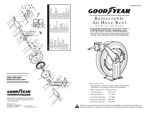
• Brass connectors on hose and reel
- 1、下载文档前请自行甄别文档内容的完整性,平台不提供额外的编辑、内容补充、找答案等附加服务。
- 2、"仅部分预览"的文档,不可在线预览部分如存在完整性等问题,可反馈申请退款(可完整预览的文档不适用该条件!)。
- 3、如文档侵犯您的权益,请联系客服反馈,我们会尽快为您处理(人工客服工作时间:9:00-18:30)。
z
rB rA
O x
B
rB/A
A
y
2008年12月4日 8:00-9:50
6.1 刚体的平动
4
6.1 刚体的平动
drB/A 0 dt
vB
drB dt
drA dt
vA
aB
dvB dt
dvA dt
aA
z
B
ห้องสมุดไป่ตู้
作平动的刚体上的所有点都以相同 的速度和加速度运动
rB
rB/A
A
B v
B
rA
O
y
a
x
A
v
A
a
可用刚体上任何一点的运动来代表整体的运动 质点
2008年12月4日 8:00-9:50
6.1 刚体的平动
5
6.1 刚体的平动
3
6.1 刚体的平动
2. 平动的描述
考虑一个作平动的刚体,设A 和 B 是刚体上任意两点
rA , rB : A、B两点的位置矢量 rB/A :B相对于A的位置矢量
rB rA rB/A
rB/A 是恒矢量:
• 由刚体的性质: |rB/A| = 常数 • 由平动的定义: rB/A方向不变
力学(Mechanics)
第六章 刚体平面运动学
Planar Kinematics Of Rigid Bodies
6.1 刚体的平动
Translation Of Rigid Bodies
2008年12月4日 8:00-9:50
6.1 刚体的平动
1
6.1 刚体的平动
1. 平动(Translation)的定义
在运动过程中,刚体上任意一条直线在各个时 刻的方向总是相同.
刚体的基本运动形式之一
2008年12月4日 8:00-9:50
6.1 刚体的平动
2
6.1 刚体的平动 两种形式的平动: ① 直线平动:
刚体上所有的点都作直线运动;
② 曲线平动: 刚体上的点的运动轨迹是曲线。
2008年12月4日 8:00-9:50
