ASTMD624标准(橡胶和热塑性弹性体抗撕裂强度)讲解
ASTM D624 硫化橡胶机械抗撕裂强度测试
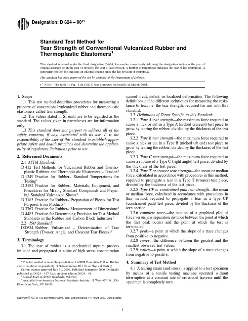
4.2This test method measures the force per unit thicknessrequired to rupture,initiate,or propagate a tear through a sheetof rubber in the form of one of several test piece geometries:4.2.1Type A,a razor-nicked test piece with a crescentshape,as shown in Fig.1,Die A.The force in this test pieceacts in a direction substantially along the major axis (length)and perpendicular to the “nick”,or razor cut.Type A is used tomeasure tear propagation and is normally cut from smaller testspecimens that can not accommodate other test types. 4.2.2Type B,a razor-nicked test piece with a crescent shape and with tab ends,as shown in Fig.1,Die B.The force in this test piece acts in a direction substantially along the major axis (length)and perpendicular to the “nick”,or razor cut.Type B also measures tear propagation and is preferred over Type A when the test sample allows.4.2.3Type C,an un-nicked test piece with a 90°angle on one side and with tab ends,as shown in Fig.1,Die C.The force acts on the test piece in a direction substantially parallel totheFIG.1Type A,B and C Tear Test Specimen CuttingDiestab ends of the specimen (45°to the 90°center angle)in thedirection of grip separation.Type C measures rupture,or tearinitiation strength at the stress concentration located at the 90°apex.If tear initiation does not occur at the apex,the results aremore indicative of tensile strength than tear strength.4.2.4Type T,a trouser tear test piece,as shown in Fig.2.Type T measures tear propagation in a direction parallel to thelength of both legs.4.2.5Type CP,a test piece described in Fig.3,which is amodified trouser tear test piece with a constrained path for thetear.Type CP also measures tear propagation in a directionparallel to the length of both legs,but the constrained pathprevents the tear from propagating away from this path,and thethicker legs eliminate the influence of leg extension which mayoccur with Type T test pieces.See (1)for more information onCP tear testing.4.3No Correlation of results from one test type to anothershould be expected,as each test type measures tear strength fora different tear specimen geometry.5.Significance and Use5.1Vulcanized rubber and thermoplastic elastomers (TPE)often fail in service due to the generation and propagation of aspecial type of rupture called a tear.This test method measuresthe resistance to tearing action.5.2Tear strength may be influenced to a large degree by stress-induced anisotropy (mechanical fibering),stress distri-bution,strain rate,and test piece size.The results obtained in a tear strength test can only be regarded as a measure under the conditions of that particular test and may not have any direct relation to service performance.The significance of tear testing must be determined on an individual application or product performance basis.6.Apparatus 6.1Testing Machine —The testing machine shall conform to the requirements as specified in Test Method D 412.It shall be capable of registering the applied forces within 62%of the total force range or capacity during the test while maintaining the specified rate of jaw separation:6.1.1For Type A,B or C test pieces,the rate of jaw separation shall be 500650mm/min.(2062.0in./min.).6.1.2For Type T and Type CP test pieces,the rate of jaw separation shall be 5065mm/min.(260.2in./min.).6.1.2.1A low inertia machine having a continuous record-ing of force is essential when using the Type T or Type CP trouser tests.N OTE 1—Inertia (pendulum)type dynamometers may give results which differ from one another because of frictional and inertial effects.A low inertia (electronic or optical transducer)dynamometer gives results which are free from these effects and is preferred.6.1.3Calibration of the testing machine shall be routinely verified according to the manufacturer’s recommendations.Verification of calibration shall be evidenced by a written record which shows the date of verification and the testing machine’s accuracy at that time.6.2The test may be conducted at elevated or lower tem-peratures listed in D 1349using equipment described in Test Method D 412.6.3Grips —The testing machine shall be equipped with grips that tighten automatically and exert a uniformpressureFIG.2Trouser Tear TestSpecimen Cross Section Detail A =125mm B =28.5mm C =5.33mm D =1.77mm E =0.75mm FIG.3Schematic diagram of “Constrained Path”tear test piece(1)across the gripping surfaces.Grips shall provide adequate pressure as tension increases to prevent specimen slippage. Constant pressure pneumatic grips are satisfactory for most specimens.Test pieces shall be inserted in the grips symmetri-cally positioned and in axial alignment with the direction of pull.The depth of insertion of the test piece in the grips must be consistent and sufficient to prevent slipping.Type T and Type CP specimens shall be inserted in the grips as shown in Fig.2.6.4Test Piece Cutting Dies—Test pieces for tear strength shall be cut from a test specimen using cutting dies conforming to one of the shapes described in Figs.1and2,or molded according to Fig.3for Type CP tests.6.4.1The inside faces of the cutting dies shall be perpen-dicular to the plane formed by the cutting edges and polished for a distance of at least5mm(0.2in.)from the cutting edge. The die shall at all times be sharp and free from nicks.6.4.2It is important that the apex of the90°angle in Die C be sharpened to provide a sharp corner.If a segmented Die C is used,the segment incorporating the apex shall extend a minimum of25mm from the apex in both directions.6.4.3Test piece cutting dies shall be routinely examined and verified for accuracy.One method may be by preparing a test piece and measuring it for conformance to the dimensions listed in Figs.1and2.Another method may be by testing of a control compound and comparing the test results with those obtained with a compound of the same formulation using dies known to be accurate.Verification shall be documented by a dated written record.6.5Nicking devices are used to make an initial cut in test pieces for Type A or B tests.6.5.1The nicking device shall secure the test piece in a manner that prevents movement,so that the cutting mechanism introduces a razor blade on a plane perpendicular to the major axis of the test piece.The blade shall be positioned to produce a precisely controlled and cleanly separated cut in the speci-men.Alternatively,a nicking die may also provide acceptable results so long as the die is routinely examined and verified for accuracy as specified in6.4.3.7.Test Piece Preparation7.1Cut test pieces shall be obtained from molded test specimen pression molded test specimen sheets shall use molds conforming to Practice D3182.Molded test specimen sheets may also be prepared by injection molding into plaques.For test pieces cut from products,Practice D3183 shall be followed.7.1.1Molded test specimen sheets shall be2.361.0mm (0.0960.04in.)thick with the milling grain orflow direction clearly marked.7.1.2Injection molded test specimen sheets may not have the same degree of anisotropy as compression molded sheets, and this may affect the tear test results.In injection molded sheets,the grain direction is parallel to theflow direction. 7.1.3Anisotropy may also affect results for test pieces cut from products.A record of the orientation of cut test pieces shall also be made in these cases.7.2Molded test pieces are molded in shapes defined by the specifications in Fig.1,Fig.2or Fig.3.Molded test pieces may produce different results from cut test pieces.7.3The usual practice is to test with the grain running the length of the test piece.For Type A,B and C test pieces,the tear would thus be recorded as across the grain.It is to be assumed,unless otherwise specified,that all Type A,B or C test pieces are prepared in this manner.Type T and CP test pieces are also prepared with the grain running parallel to the length.This means that for Type T and CP tests the tear will be parallel to the grain.Where grain effects are significant and are to be evaluated,an additional set of test pieces shall be prepared with the grain running across the length.Results so obtained shall be recorded as with the grain for Type A,B orC tests and across the grain for Type T and CP tests.7.4Using the cutting die for the desired test type,cut the test pieces from the sheet with a single impact stroke(by hand or machine)to ensure smooth cut surfaces.7.5For Type A and B test pieces,nick the test piece using the nicking device described in6.5.1.Wet the blade with water or soap solution prior to nicking the test piece.Nick the test piece to a depth of0.5060.05mm(0.02060.002in.)with a single stroke of the blade.If a nicking die is used,the nick is formed when the test piece is cut from the sheet.7.5.1To assure a proper cut with the nicking device,one or two preliminary nicks shall be made on extra test pieces and the depth of the cut checked using a microscope with a minimum of103magnification.7.6For Type T and CP test pieces,an initial cut should be made with a razor blade or sharp knife.The last1mm (approximately)of the cut shall be made with a single stroke.7.6.1Type T test pieces shall have an initial cut of4065 mm as shown in Fig.2.7.6.2Type CP test pieces shall have an initial cut of6065 mm made down the groove between the two legs.7.7Three test pieces per sample shall be tested for tear strength,and the median value of the test pieces reported as a test result.If an individual test piece tear strength value deviates by more than20%from the median of all three test pieces,two additional test pieces shall be tested and the median of allfive values reported.7.7.1Tear testing is inherently a highly variable measure-ment since it has many characteristics similar to fatigue testing and is known to give widely dispersed test results,frequently with a non-normal distribution.For referee tear testing,a minimum offive test pieces is recommended.7.8Measure the thickness of each test piece.7.8.1For Type A,B,and C test pieces,measure the thickness at three places across the width,near the center,using a micrometer conforming to Practice D3767.One of the measurements should be at the slit or apex.Record the median value for calculation of test results.7.8.2For Type T test pieces,measure the thickness at three places across the length and record the median value.7.8.3For Type CP test pieces,the thickness of the tear path may be measured one of two ways:(1)the total thickness of the test piece along the groove is measured at three places, averaged,and3.60mm is subtracted to account for the mold insert sections that form the groove;or(2)the torn surface is examined with a small binocular magnifier with agraduatedreticle and the thickness measured and averaged.The second method is more accurate,but the two methods have been found to agree to within about5%.For routine work thefirst method has been found to be satisfactory.Based on the mold dimen-sions,the thickness is approximately between1.70and1.80 mm.8.Test Piece Conditioning8.1Cut surfaces of vulcanized rubber undergo a change over a period of time that may affect the initiation of tearing. Therefore,it is important that the conditioning intervals after using cutting dies,nicking devices,razor blades or knives be followed.Deviation from these intervals may affect the test results.8.2Test pieces shall be protected from exposure to light during the interval from vulcanization to testing.8.3The minimum time between vulcanization and testing shall be16h.8.4Test pieces shall be conditioned at a standard laboratory temperature of2362°C as defined in Practice D1349for a minimum of3h before nicking or cutting.If the material is affected by moisture,the relative humidity shall be maintained at5065%and the specimen shall be conditioned for24h prior to testing.8.5Test pieces may be nicked or cut and tested immediately after conditioning but the maximum time between nicking or cutting and testing shall be24h.8.6If test piece preparation involves buffing,the interval between buffing and testing shall not exceed72h.Nicking or cutting shall be performed after any aging treatment.8.7If the test is to be carried out at a temperature other thana standard laboratory(room)temperature,the test pieces shall be conditioned at the test temperature for a minimum time sufficient to reach temperature equilibrium prior to testing.This period should be kept as short as possible to avoid aging the test pieces.9.Test Temperature9.1Unless otherwise specified,the standard test tempera-ture shall be2362°C(73.463.6°F).When testing at some other temperature is required,the temperature specified shall be one of those listed in Practice D1349,and the report shall include a statement of the test temperature and the length of time the test piece was conditioned.10.Test Procedure10.1Prepare the test pieces and condition them as described in Sections7and8.10.2Place the test piece in the grips of the testing machine using care to adjust the test piece so that it will be strained uniformly along its length,and that sufficient material is clamped in the grips to minimize slippage.10.3Start the machine at a steady rate of grip separation.10.3.1For Type A,B or C test pieces,the rate of jaw separation shall be500650mm/min.(2062.0in./min.).10.3.2For Type T and Type CP test pieces,the recom-mended rate of jaw separation shall be5065mm/min.(26 0.2in./min.).10.4Strain the test piece until it is completely ruptured.10.5Record the maximum force for Type A,B or C test pieces.For Type T or CP test pieces,make a strip chart or a continuous recording of the force throughout the tearing process.11.Calculation11.1Calculate the tear strength,T s,in kilonewtons per meter of thickness,by the formula:T s5F/d(1) Where:F=the maximum force,in N,for Types A,B or C.For Type T and CP tests,F is the peak,valley,mean ormedian force obtained from the recording or auto-graphic trace,in N(See11.3),andd=the median thickness of each test piece,in mm.11.1.1When anisotropic effects are evaluated,determine the median and the range of the values for each direction.Express the results to the nearest0.1kN/m.11.1.2Alternatively,the tear strength may be expressed in lbf/in.To convert from lbf/in to kN/m,multiply by0.175. 11.2The recorded plot of stress versus displacement for Type A,B or C test pieces is a sharply increasing force until catastrophic failure occurs,at which point the force sharply decreases.The peak or maximum force value is used to calculate the tear strength.11.3For Type T and CP test pieces,the complete trace of force throughout the tearing process forms a saw-toothed curve consisting of peaks and valleys.Two primary types of saw toothed curves,a and b are illustrated in Fig.4.Saw toothed curves can be interpreted in several different ways.11.3.1Curve a in Fig.4illustrates a characteristic tear commonly called“knotty tear”.The word“knotty”designates a large magnitude transient increase in tearing force followed by a precipitous decrease.With this type of tear,the increase-decrease process repeats in a cyclic fashion.Each increasing force stage eventually produces a rapid tear rupture which relieves concentrated stress and increases torn length.Just as the maximum force reached before tearing is a measure oftearFIG.4Smooth Tear and Knotty Tear CurveTypesstrength,the level to which the force decreases before tear pauses also indicates important compound tear properties. 11.3.2Curve b in Fig.4illustrates a typical“smooth tear”curve with minimal tear force amplitudes between the tear initiation force and the tear pause force.11.4Peak Only Analysis uses the peak forces generated during the tearing process.The peak force value obtained defines the maximum stress concentration that the compound will bear before catastrophic failure occurs.This method should be used on curves resembling example a in Fig.4. 11.4.1The sum of the peak force values divided by the number of peaks defines the mean peak force.11.4.2In establishing the repetitive pattern of transient tearing that creates the saw-toothed curve,it is not uncommon to have the initial orfinal peaks,or both,be inconsistent in magnitude with those in the center of the curve.Such peaks can be abnormally low or high depending on the physical proper-ties of the compound and how quickly the transient tear pattern is established or ended.For any complete trace,individual peak force values that deviate from the mean by20%or more should be discarded and a new mean calculated to correct for abnormal values.11.5Valley Only Analysis uses the forces(opposite of peaks)at the valley positions on the saw-toothed curve as a measure of the force to which the stress concentration must be relaxed for tearing to cease.This method should be used on curves resembling example a in Fig.4.11.5.1The sum of the forces at each valley are divided by the number of valleys to calculate the mean valley force.As with the peak only analysis,initial andfinal valley forces may be abnormal.For any complete trace,individual valley force values that deviate from the mean by20%or more should be discarded and a new mean calculated to correct for abnormal values.11.6Mean Force Analysis of type a curves in Fig.4uses the arithmetic mean of the mean peak force and the mean valley force.This should be considered as an average tear force since it gives equal consideration to peak and valley responses. Note that the mean force does not indicate the difference between peak and valley forces.It is possible for two tear curves to have the same mean force when one has a large difference between peaks and valleys,while the other has a small difference between peaks and valleys.11.7Peak and Valley Analysis uses a concise report of typea curves in Fig.4as the mean force value with a plus or minus value determined by the average of the greatest four to six peak force values and the average of the lowest four to six valley force values.11.8Total Work Analysis measures the total work required to tear the test piece by measuring the area under the force-displacement test curve.The area can be measured electronically by properly equipped instruments or measured manually by use of a planimeter.The mean force can be calculated by dividing the area under the curve by the displacement indicated on the complete trace curve.As with other mean tear force values,the total work analysis method does not account for the magnitude of variation from the mean. The total work analysis method can be used on both types of curves shown in Fig.4.11.9Manual Curve Analysis may also be used as a method of calculating median mean force values.11.9.1Manual Curve Analysis for Type a Curves(Knotty Tear)—Count the number of peaks.To obtain the median force value,locate,with a horizontal line,the lowest or No.1peak force value.Move upward from this line the required number of peaks to arrive at the median peak force value.In Fig.4,the lowest peak force and the median peak force points are identified.11.9.2Manual Curve Analysis for Type b Curves(Smooth Tear)—Smooth type tear curves often consist of a series of tear propagation or torn length sequences,each at essentially constant tearing force.In Fig.4,Curve b shows two such sequences(1)and(2),with(2)approximately twice the length of(1).The tear strength for this type of curve should be calculated based on a weighted average force basis.A median force is specified for Type b tear curves because it is easier to obtain than an average,and it does not give undue weight to abnormally large or small peak forces.11.9.3A general formula for weighted average tear force is:Tear Force~Weighted Average!5(2)n0~TF1!1N2~TF2!1····N i~TF i!(~n i!where:n0=smallest observable segment(chart distance)for a constant tear force segment,N2=n2/n0=the weighting factor for constant tear force (TF)segment TF2,with n2as the actual segmentdistance for TF2,and((n i)=the sum of all n0values,or total torn length,or chart paper distance measured in n0units.12.Report12.1Report the following information:12.1.1Median test results of three orfive test pieces, calculated in accordance with Section11.12.1.2Indicate which Type of test piece was used(A,B,C, T or CP)and whether the test piece was die cut,molded to form,or obtained from a product.12.1.3For Type T,and CP test pieces the tear curve analysis method shall also be specified.12.1.4Test piece thickness.12.1.5The depth of the nick for Type A or B test pieces.12.1.6Grain direction if other than the conventional orien-tation(see Section7.3).Indicate as with the grain or across the grain,or unknown if the conventional orientation is not followed.12.1.7Maximum force,F for Type A,B or C test pieces,or the mean or median force for Type T and CP test pieces.For Type T and CP test pieces with tear curves similar to curve a in Fig.4,the mean or median peak and the mean or median valley forces should also be reported.12.1.8Date of test and date of vulcanization of the test sample,if known.12.1.9Test temperature,when the test is conducted at conditions other than standard roomtemperature.12.1.10Relative humidity when it is known that the mate-rial is sensitive to humidity.12.1.11Type of testing machine and grips employed.12.1.12Any other details that are pertinent to the history ofthe test piece.13.Precision and Bias413.1This precision and bias section has been prepared inaccordance with Practice D 4483.Refer to this practice forterminology and other statistical calculation details.13.2A Type 1(interlaboratory)precision was evaluated in1981and another in 1988.Test repeatability and reproducibil-ity are short term;a period of a few days separates replicate testresults.A test result is the median value,as specified by thismethod,obtained on three determinations or measurements.13.3In the 1981test program,one material (one rubbercompound)was tested in four laboratories on two separatedays.In the 1983test program,two materials (rubbers)weretested in five laboratories on two separate days.For bothprograms tests were conducted for dies B and C only.13.4The results of the precision calculations for repeatabil-ity and reproducibility are given in Tables 1and 2.13.5The precision of this test method may be expressed inthe format of the following statements which use an appropri-ate value of r,R,(r)or (R),that is,that value to be used indecisions about test results (obtained with the test method).The appropriate value is that value of r or R associated with amean level in the precision tables closest to the mean levelunder consideration at any given time,for any given material inroutine testing operations.13.6Repeatability —The repeatability,r,of this test methodhas been established as the appropriate value tabulated in the precision tables.Two single test results,obtained under normal test procedures,that differ by more than this tabulated r (for any given level)must be considered as derived from different or non-identical sample populations.13.7Reproducibility —The reproducibility,R,of this test method has been established as the appropriate value tabulated in the precision tables.Two single test results obtained in two different laboratories,under normal test method procedures,that differ by more than the tabulated R (for any given level)must be considered to have come from different or non-identical sample populations.13.8Repeatability and reproducibility expressed as a per-centage of the mean level,(r)and (R),have equivalent application statements as above for r and R.For the (r)and (R)statements,the difference in the two single test results is expressed as a percentage of the arithmetic mean of the two test results.13.9Bias —In test method terminology,bias is the differ-ence between an average test value and the reference (or true)test property value.Reference values do not exist for this test method since the value (of the test property)is exclusivelydefined by the test method.Bias,therefore,cannot be deter-mined.14.Keywords14.1tear resistance;tear strength;tear propagation;nickedtear specimen;trouser tear;constrained path tear 4The full details and test results of the interlaboratory test program used for this precision section are contained in a Research Report RR:D11-1027obtainable fromASTM headquarters.TABLE 1Type 1Precision for Dies B and C (1981)A Die Average Value Within Laboratories Between Laboratories (kN/m)S r r (r )S R R (R )B 81.6 5.1114.517.716.847.658.3C 44.5 3.8410.924.4 4.6913.329.8A S r =repeatability standard deviation.r =repeatability =2.833S r .(r )=relative repeatability,expressed as a percentage of the average value.S R =reproducibility standard deviation.R =reproducibility =2.833S R .(R )=relative repeatability,expressed as a percentage of the average value.TABLE 2Type 1Precision for Dies B and C (1983)ADieMaterial Average Value Within Laboratories Between Laboratories (kN/m)S r r (r )S R R (R )B(1)H1432747.4 2.29 6.4713.714.440.785.8B(2)R1952685.1 5.5015.618.325.070.883.2C(3)H1432740.0 1.14 3.238.19.3526.466.1C(4)R1952649.7 2.838.0216.18.5824.348.8A S r =repeatability standard deviation.r =repeatability =2.833S r .(r )=relative repeatability,expressed as a percentage of the average value.S R =reproducibility standard deviation.R =reproducibility =2.833S R .(R )=relative repeatability,expressed as a percentage of the averagevalue.APPENDIX(Nonmandatory Information)X1.SIGNIFICANCE OF DIFFERENT TEAR TEST METHODSX1.1BackgroundX1.1.1To characterize rubbers adequately,knowledge oftheir rupture properties is essential.Tear strength is importantin the performance of many rubber products.This appendixgives some background discussion based on the work cited in(1)and (2)at the end of the standard.X1.1.2One reason for the lack of discrimination in manytear tests is a direct influence of compound modulus onmeasured tear strength.Fig.X1.1is a plot of D 624Die C tearstrength as a function of modulus (300%)for data taken fromthe literature.This shows tear strength to be strongly correlatedwith modulus (correlation coefficient of 0.90).Thus bothmodulus and tear strength are being measured in unknownproportions.Theoretical calculations show that the tear ruptureforce of Die C specimen measurements is approximately equalto the square root of the tangent modulus-tear strength product.X1.1.3It should not be inferred that modulus will have noeffect on tear strength;however,the influence of modulusshould be allowed to operate in the immediate tearing zone andnot in regions of the test specimen remote from the locus oftear.In short,a tear test specimen should not be an ill-shapedmodulus (tensile)test specimen.X1.1.4Rivlin,Thomas,et al.(2)developed tear tests basedon theoretical analysis of crack growth behavior.For flat sheettest specimens they defined a tearing energy or strength T,thatis independent of the geometry of the test specimen providedthe stored energy density of the specimen could be measured.Three types of test specimens were used:the strip or tensilespecimen,the pure shear specimen and the trouser tear speci-men.The relation for the tearing energy with the trouserspecimen is:T 52l F /t 2wE (X1.1)where:T =tear strength in force/unit thickness (per unit length torn),l =extension ratio in legs of piece,F =force applied to ends of piece,w =total width of specimen,T =thickness,and E =strain energy density in legs of piece.For certain vulcanizates,if w is chosen large enough,the elongation of the legs is minimal (l -[1)and E is essentially zero.Then:T 52F /t (X1.2)X1.1.5Many published reports imply that Eq X1.2is satisfactory to use for routine tear measurements.However,two serious deficiencies are evident:For many compounds there is appreciable leg extension (l fi1)even if w is chosen to be quite wide;and secondly knotty tear is frequently encountered and the tear deviates laterally and tears through one leg of the test specimen.Development of Eq X1.1and X1.2is based on tear propagation down the central axis of the test piece.X1.1.6Leg extension can be allowed for if strain energy density E is known,but a separate stress-strain curve is required.When one leg of the test specimen is torn through,further testing is precluded with that specimen.These deficien-cies very often preclude any quick and meaningful routine tear strength measurement with the simple trouser test piece.X1.1.7In order to avoid these deficiencies,it is necessary to reinforce the legs to prevent their elongation and to provide a path of least resistance for tear propagation.The “constrained path”,or CP tear test specimen,as described in (1),meets this requirement.It is shown in Fig.3of D 624as a molded piece 125mm long,28.5mm wide,with a nominal thickness of 5mm.A longitudinal groove with the indicated cross-sectional geometry is molded into the piece.The legs are reinforced with fabric placed in the mid-plane of the piece to avoid an appreciable bending moment and to facilitate its reinforcing action during tear testing.The bottom of the mold contains two puncture pins to hold the fabric as the mold is closed and to prevent a lateral fabric shift.X1.2Constrained Path Tear Curves X1.2.1Two types of tear curves are obtained for various vulcanizates (see Fig.4of D 624).For Curve (b ),smooth tear,the tearing load fluctuates only slightly and the rate of tear propagation is essentially continuous and roughly equal to one-half that of jaw separation.Curve (a )is typical of knotty tear,consisting of a series of peak loads,each correspondingtoFIG.X1.1Plot of ASTM Die C Tear Strength as a Function ofStress at 300%Elongation。
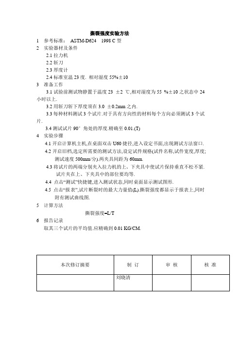
撕裂强度实验方法
撕裂强度实验方法
1 参考标准:ASTM-D624 1998 C型
2 实验器材及条件
2.1拉力机
2.2斩刀
2.3厚度计
2.4标准室温23度. 相对湿度55%±10
3 准备工作
3.1试验前测试物静置于温度23 ±2 ℃,相对湿度为55 %±10之状态中24
小时以上.
3.2用斩刀斩下厚度须在3.0 ±0.2mm之内.
3.3每种材料测试3个试片.对于具有方向性的材料每个方向必须测试3个试
片.
3.4测试试片90°角处的厚度.精确至0.01.(T)
4实验步骤
4.1开启计算机主机,在桌面双击U60捷径,进入设定书面,出现测试方法窗口.
4.2开启旧档,选定所需要的测试方法,设定试件规格(试件名称,试件宽度,厚度;
测试速度500mm/分).两夹具间距为60mm.
4.3将试片的两端分别夹入拉力机的上、下夹具中使试片保持垂直不松不紧.
试片夹在上、下夹具中的部位要均等.
4.4 点击“测试”快捷键,进入测试状态,同时桌面显示测试图形.
4.5 点击“报表”,试片断裂时的最大力量值(L).撕裂强度都显示于报表上,同时
附有测试曲线图.
5 计算方法
撕裂强度=L/T
6 报告记录
取其三个试片的平均值.应精确到0.01 KG/CM.
本次修订摘要制订审核核准
刘晓清。
撕裂强度测试(ASTM D 624)
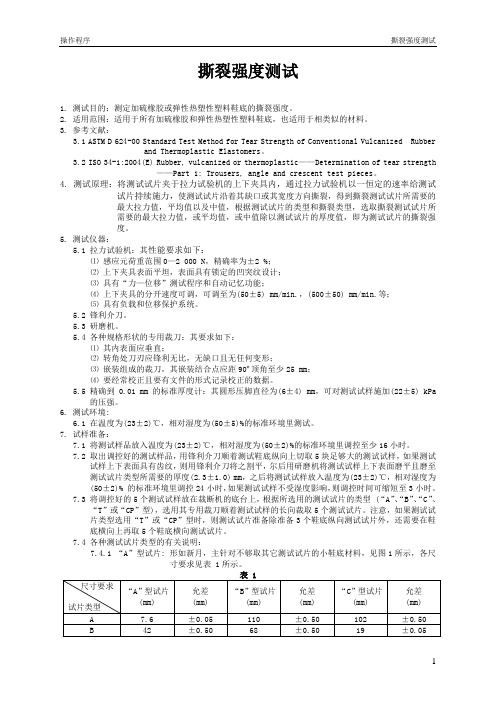
撕裂强度测试1. 测试目的:测定加硫橡胶或弹性热塑性塑料鞋底的撕裂强度。
2. 适用范围:适用于所有加硫橡胶和弹性热塑性塑料鞋底,也适用于相类似的材料。
3. 参考文献:3.1 ASTM D 624-00 Standard Test Method for Tear Strength of Conventional Vulcanized Rubberand Thermoplastic Elastomers。
3.2 ISO 34-1:2004(E) Rubber, vulcanized or thermoplastic——Determination of tear strength——Part 1: Trousers, angle and crescent test pieces。
4. 测试原理:将测试试片夹于拉力试验机的上下夹具内,通过拉力试验机以一恒定的速率给测试试片持续施力,使测试试片沿着其缺口或其宽度方向撕裂,得到撕裂测试试片所需要的最大拉力值,平均值以及中值,根据测试试片的类型和撕裂类型,选取撕裂测试试片所需要的最大拉力值,或平均值,或中值除以测试试片的厚度值,即为测试试片的撕裂强度。
5. 测试仪器:5.1 拉力试验机:其性能要求如下:⑴感应元荷重范围0—2 000 N,精确率为±2 %;⑵上下夹具表面平坦,表面具有锁定的凹突纹设计;⑶具有“力—位移”测试程序和自动记忆功能;⑷上下夹具的分开速度可调,可调至为(50±5) mm/min.,(500±50) mm/min.等;⑸具有负载和位移保护系统。
5.2 锋利介刀。
5.3 研磨机。
5.4 各种规格形状的专用裁刀:其要求如下:⑴其内表面应垂直;⑵转角处刀刃应锋利无比,无缺口且无任何变形;⑶嵌装组成的裁刀,其嵌装结合点应距90º顶角至少25 mm;⑷要经常校正且要有文件的形式记录校正的数据。
5.5 精确到0.01 mm的标准厚度计:其圆形压脚直径为(6±4) mm,可对测试试样施加(22±5) kPa的压强。
橡胶制品十五种常见试验测试项目和标准
橡胶制品十五种常见试验测试项目和标准橡胶制品十五种常见试验测试项目和标准1.胶料硫化特性GB/T 9869—1997橡胶胶料硫化特性的测定(圆盘振荡硫化仪法)GB/T16584—1996橡胶用无转子硫化仪测定硫化特性ISO 3417:1991橡胶—硫化特性的测定——用摆振式圆盘硫化计ASTMD2084-2001用振动圆盘硫化计测定橡胶硫化特性的试验方法ASTM D5289-1995(2001)橡胶性能—使用无转子流变仪测量硫化作用的试验方法DIN53529-4:1991橡胶—硫化特性的测定——用带转子的硫化计测定交联特性。
2.橡胶拉伸性能GB/T528—1998硫化橡胶或热塑性橡胶拉伸应力应变性能的测定ISO37:2005硫化或热塑性橡胶——拉伸应力应变特性的测定ASTMD412-1998(2002)硫化橡胶、热塑性弹性材料拉伸强度试验方法JISK6251:1993硫化橡胶的拉伸试验方法DIN 53504-1994硫化橡胶的拉伸试验方法。
3.未硫化橡胶门尼粘度GB/T1232.1—2000未硫化橡胶用圆盘剪切粘度计进行测定—第1部分:门尼粘度的测定GB/T1233—1992橡胶胶料初期硫化特性的测定—门尼粘度计法ISO289-1:2005未硫化橡胶——用剪切圆盘型黏度计—第一部分:门尼黏度的测定ISO289-2-1994未硫化橡胶——用剪切圆盘型黏度计测定—第二部分:预硫化特性的测定ASTMD1646-2004橡胶粘度应力松驰及硫化特性(门尼粘度计)的试验方法JISK6300-1:2001未硫化橡胶-物理特性-第1部分:用门尼粘度计测定粘度及预硫化时间的方法。
4.压缩永久变形性能GB/T 7759-1996硫化橡胶、热塑性橡胶在常温、高温和低温下压缩永久变形测定ISO815:1991硫化橡胶、热塑性橡胶在常温、高温和低温下压缩永久变形测定ASTM D395-2003橡胶性能的试验方法压缩永久变形JIS K6262:1997硫化橡胶及热塑性橡胶压缩永久变形试验方法。
塑胶测试标准 (3)
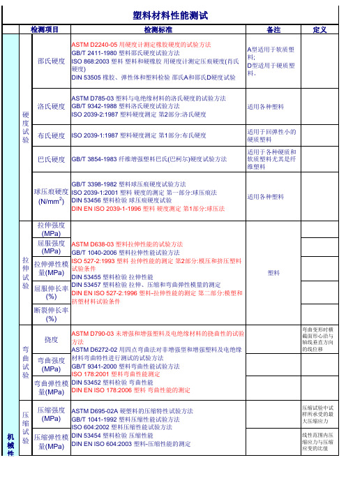
巴氏硬度 GB/T 3854-1983 纤维增强塑料巴氏(巴柯尔)硬度试验方法
适用各种塑料
适用于回弹性小的 硬质塑料 适用于各种硬质和 软质塑料尤其是纤 维塑料
GB/T 3398-1982 塑料球压痕硬度试验方法
球压痕硬度 ISO 2039-1:2001 塑料 硬度的测定 第一部分:球压痕法
(N/mm2) DIN 53456 塑料检验 球压痕硬度试验
载荷下挠曲温 度
ASTM D648-06 弯曲载荷下塑料变形温度的测定 GB/T 1634.2-2004 塑料 载荷下挠曲温度的测定 第2部分:塑料和 硬橡胶 ISO 75-2:2004 塑料 载荷下挠曲温度的测定 第2部分:塑料和硬橡 胶 DIN 53461 塑料检验 热变形温度的测定 DIN EN ISO 75-2:2004 塑料 载荷下挠曲温度的测定 第2部分:塑 料和硬橡胶塑料
气味试验 (等级)
SAE J1351 GM 9130P GME 60276 通用标准 气味测试 PV 3900-2000 大众标准 气味测试 TSM0505G-2005 丰田标准 FLTM BO 131-01 ES-X 60250 MS 300-34 EDS-T-7603
甲醛含量 (mg/kg)
GME 60271 通用标准 甲醛含量 PV3925 大众标准 甲醛含量 SQR.04.096
ASTM D256-06a 测定塑料悬臂梁试样抗摆锤冲击性能方法
冲 击
悬臂梁冲击 GB/T 1843-1996 塑料悬臂梁冲击试验方法
ISO 180:2001 塑料 悬臂梁冲击性能的测定
试
验 落锤冲击
落球冲击 (/)
GB/T 14485-1993 工程塑料硬质塑料板材及塑料件耐冲击性能试 验方法:落球法 PV 3905:1972 大众标准 有机材料 落球试验
ASTM D264中文标准
编号:D 624-00 (2007年重申批准)常规硫化橡胶和热塑合成橡胶撕裂强度的标准测试方法1 此项标准在固定编号B 117下发布,紧随编号的数字表示标准采纳的年度,如果是修正,数字表示最后一次修正的年度。
在括号内的数字表示最后一次重申批准的年度。
上标ε表示自最后一次修正或重申批准以来的编辑改动。
此项标准已被批准供美国国防部下属机构使用。
1. 范围1.1 此测试方法描述了测定常规硫化橡胶和热塑合成橡胶撕裂强度的程序。
1.2 以国际单位(SI)为单位的数值应被认为是标准。
在括号内的数值起参照作用。
1.3此项标准不包括与其应用有关的所有的安全隐患。
此项标准的使用者有责任在使用前建立合适的安全健康规范以及决定法规限制是否适用2 参考文件2.1 ASTM标准:2 D 412硫化橡胶和热塑合成橡胶的拉伸试验方法 D 1349橡胶规范---测试的标准温度 D 3182 混合标准化合物及制备标准硫化橡胶薄片用橡胶材料、设备及工序的标准实施规程 D 3183 橡胶实施规范---从橡胶制品中制备试验目的用试片 D 3676 橡胶的标准规程----尺寸测量 D 4483 评定橡胶和炭黑制造工业试验方法标准的精度的实施规程2.2 ISO标准:ISO/34硫化橡胶----.撕裂强度的测定(裤型,角形和新月形试片)3 ------------------------------1 此测试方法属于ASTM D 11橡胶委员会的工作范围,是其下属D11.10物理测试子委员会的直接责任。
目前的版本在批准,2008.01出版。
原始的版本在1941年批准。
上一个版本在2000年批准,编号为D 624-00ε 1.2 如需参照ASTM 标准,访问ASTM网站,或联系ASTM客户服务如需要《ASTM标准年鉴》的内容信息,浏览ASTM网站的标准索引页。
3 术语3.1 橡胶的撕裂是机械破裂过程,在由割裂,缺陷或局部变形造成的受力集中处开始和扩散。
ASTM-D624-00(2007)常规硫化橡胶和热塑橡胶撕裂强度测试方法

编号:D 624-00 (2007年重申批准)常规硫化橡胶和热塑合成橡胶撕裂强度的标准测试方法1此项标准在固定编号B 117下发布,紧随编号的数字表示标准采纳的年度,如果是修正,数字表示最后一次修正的年度。
在括号内的数字表示最后一次重申批准的年度。
上标ε表示自最后一次修正或重申批准以来的编辑改动。
此项标准已被批准供美国国防部下属机构使用。
1.范围1.1 此测试方法描述了测定常规硫化橡胶和热塑合成橡胶撕裂强度的程序。
1.2以国际单位(SI)为单位的数值应被认为是标准。
在括号内的数值起参照作用。
1.3此项标准不包括与其应用有关的所有的安全隐患。
此项标准的使用者有责任在使用前建立合适的安全健康规范以及决定法规限制是否适用2 参考文件2.1 ASTM标准:2D 412硫化橡胶和热塑合成橡胶的拉伸试验方法D 1349橡胶规范---测试的标准温度D 3182 混合标准化合物及制备标准硫化橡胶薄片用橡胶材料、设备及工序的标准实施规程D 3183 橡胶实施规范---从橡胶制品中制备试验目的用试片D 3676 橡胶的标准规程----尺寸测量D 4483 评定橡胶和炭黑制造工业试验方法标准的精度的实施规程2.2 ISO标准:ISO/34硫化橡胶----.撕裂强度的测定(裤型,角形和新月形试片)3------------------------------1此测试方法属于ASTM D 11橡胶委员会的工作范围,是其下属D11.10物理测试子委员会的直接责任。
目前的版本在2007.11.01批准,2008.01出版。
原始的版本在1941年批准。
上一个版本在2000年批准,编号为D 624-00ε1.2如需参照ASTM 标准,访问ASTM网站,或联系ASTM客户服务Service@. 如需要《ASTM标准年鉴》的内容信息,浏览ASTM网站的标准索引页。
3 术语3.1 橡胶的撕裂是机械破裂过程,在由割裂,缺陷或局部变形造成的受力集中处开始和扩散。
橡胶的抗拉强度、断裂伸长率、回弹率的测试标准_概述说明

橡胶的抗拉强度、断裂伸长率、回弹率的测试标准概述说明1. 引言1.1 概述橡胶是一种具有优异弹性的材料,被广泛应用于各个领域,如汽车工业、医疗器械、建筑工程等。
在使用橡胶材料时,了解其抗拉强度、断裂伸长率和回弹率等物理性能指标非常重要。
这些指标可以帮助我们评估橡胶的质量和适用范围,从而确保产品的可靠性和安全性。
因此,对于这些指标的测试标准的制定具有重要意义。
1.2 文章结构本文将分为五个主要部分进行探讨。
首先,在引言部分将简要介绍本文的目的和结构。
接下来,在第二部分中,我们将详细介绍橡胶抗拉强度测试所使用的方法和相关标准,包括ASTM和ISO标准。
第三部分将重点讨论橡胶的断裂伸长率测试,并提供ASTM和ISO标准的综述。
第四部分将涵盖橡胶回弹率测试的方法以及相应的ASTM和ISO标准。
最后,在结论部分总结并提供本文的主要观点。
1.3 目的本文旨在全面概述关于橡胶材料抗拉强度、断裂伸长率和回弹率的测试标准。
通过详细介绍这些测试方法以及ASTM和ISO标准,我们希望读者能够更好地理解如何评估橡胶材料的性能特征,并在实际应用中正确选择合适的标准进行测试。
同时,文章还将对这些标准的适用范围和限制进行分析,使读者能够更好地理解其实验结果的可靠性和可行性。
最终,本文将为相关从业人员和研究者提供一个有价值的参考资源,促进橡胶材料性能测试领域的发展与进步。
2. 橡胶的抗拉强度测试标准2.1 测试方法介绍橡胶材料的抗拉强度是指在拉伸过程中所能承受的最大力量,通常以N/mm²(或MPa)表示。
为了确定橡胶材料的抗拉性能,需要进行相应的测试。
抗拉试验是通过施加力量来使样本发生拉伸,测量样本在拉伸过程中所承受的力量和变形。
这些测试通常在实验室环境下进行,使用特定设备和标准化程序。
2.2 ASTM标准概述美国材料与试验协会(ASTM)是一个非营利组织,致力于制定和发布材料及其产品的相关标准。
对于橡胶材料的抗拉强度测试,ASTM D412-16《标准试验方法-切割式、不机动式热硫化橡胶和热塑性弹性体力学性能测定》提供了详细说明和指导。
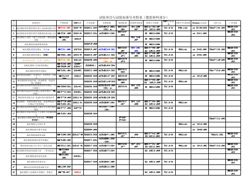
橡胶和热塑性弹性体性能检测标准 对照表
GME60221-1998
GM4298P-1997 GMI60206-1998 GM9102P-1997
39
O型圈的试样法
ASTMD1414
40
橡胶特性的测试方法 液体浸没时间的长 度变化
41 橡胶特性的测试方法 特定应力下的延伸
ASTM D14601986 2001)
ASTMD1456
42
橡胶中溶剂抽出物的测定
GB/T3516-1994
43
弹性织物拉伸的试验方法(拉伸试验机的恒 速拉伸试验
ASTM297-1993 (2002)e2
22
硫化橡胶绝缘电阻率的测定
GB/T1692-1992
JISK6271-2001
ASTMD991-1989 (2005)
23
橡胶标准试验方法-热空气老化试验 GB/T3512-2001 ISO188--98 JISK6257-2003 ASTMD573-2004
24 硫化橡胶热氧老化试验方法 ( 管式仪法)
艾默生企业标准
FiatAuto企业标准
TS2-10-03
TS2-10-03
std 50417-2002
上海大众
广州电装
HESD 32001982
HESD 32001982
VDA675 235-1992
VDA675 225(缺)
std 50420
VDA675 241-1992 VDA675 242-1992
8
未硫化橡胶门尼粘度的测定
GB/T1233-1992 GB/T9869-1997
9
硫化橡胶回弹性的测定
GB/T1681-1991
10
硫化橡胶低温脆性(单试样法、多试样法)的测 定
橡胶拉伸强度测试标准

橡胶拉伸强度测试标准橡胶制品作为一种重要的工业原料,在各种机械设备和产品中都有着广泛的应用。
而橡胶制品的拉伸强度是衡量其质量和性能的重要指标之一。
因此,对橡胶制品的拉伸强度进行标准化测试具有重要意义。
本文将介绍橡胶拉伸强度测试的标准方法和注意事项,以帮助相关行业进行准确、可靠的测试工作。
首先,橡胶拉伸强度测试的标准方法主要包括两种,常温下的拉伸试验和高温下的拉伸试验。
在进行常温下的拉伸试验时,需要根据具体橡胶制品的特性和用途选择合适的测试标准,常用的有GB/T 528-2009《橡胶和胶制品拉伸性能试验方法》和ASTM D412-06a《Standard Test Methods for Vulcanized Rubber and Thermoplastic Elastomers-Tension》等。
而在进行高温下的拉伸试验时,则需要参照相应的热老化试验标准,如GB/T 3512-2001《橡胶老化试验方法》和ASTM D573-04《Standard Test Method for Rubber-Deterioration in an Air Oven》等。
其次,进行橡胶拉伸强度测试时需要注意的事项有以下几点,首先,要选择合适的试验样品,保证其代表性和一致性。
其次,要严格按照标准方法进行试验,避免操作不当和设备故障对测试结果的影响。
另外,还需要注意试验环境的控制,尤其是在进行高温下的拉伸试验时,要保证试验环境的稳定和准确。
最后,对测试结果的处理和分析也是十分重要的,要进行合理的数据处理和结果评定,确保测试结果的可靠性和准确性。
总之,橡胶拉伸强度测试是衡量橡胶制品质量和性能的重要手段,标准化的测试方法和严格的试验操作是保证测试结果准确可靠的关键。
希望本文介绍的内容能够对相关行业进行橡胶拉伸强度测试工作提供一定的参考和帮助,促进橡胶制品质量的提升和行业的发展。
橡胶撕裂强度的国家试验标准
橡胶撕裂强度的国家试验标准1. 范围本标准规定了橡胶撕裂强度的试验方法,包括试验原理、试验设备、试样制备、试验步骤、结果计算与表示以及试验报告等内容。
本标准适用于各种橡胶材料的撕裂强度测试。
2. 规范性引用文件在本标准中,引用了以下文件:GB/T 2941-2006 橡胶物理试验方法总则GB/T 528-2009 硫化橡胶或热塑性橡胶拉伸应力应变性能的测定HG/T 2024-2004 橡胶拉伸强度和扯断伸长率的测定3. 术语和定义在本标准中,使用以下术语和定义:撕裂强度:指橡胶材料在规定条件下,单位厚度所承受的最大撕裂力。
撕裂模量:指橡胶材料在规定条件下,单位厚度所承受的平均撕裂力。
4. 试验方法在本标准中,规定了以下两种试验方法:直角撕裂试验:将橡胶试样以直角方向置于拉力机上,以一定的速度拉伸至试样破裂。
该方法适用于测试各种橡胶材料的撕裂强度。
纵横拉伸试验:将橡胶试样分别沿纵向和横向方向置于拉力机上,以一定的速度拉伸至试样破裂。
该方法适用于测试橡胶材料的纵横方向撕裂强度。
5. 试验原理在本标准中,规定了以下试验原理:当橡胶试样受到撕裂力的作用时,试样内部会产生相应的应力应变。
当应力应变达到一定值时,试样就会发生破裂。
通过测量试样破裂时的撕裂力,可以计算得到撕裂强度和撕裂模量。
在直角撕裂试验中,试样以直角方向受到撕裂力的作用,当撕裂力达到最大值时,试样发生破裂。
通过测量试样破裂时的最大撕裂力,可以计算得到撕裂强度。
在纵横拉伸试验中,试样分别沿纵向和横向方向受到撕裂力的作用,当撕裂力达到最大值时,试样发生破裂。
通过测量试样破裂时的最大撕裂力,可以计算得到纵横方向的撕裂强度。
6. 试验设备在本标准中,规定了以下试验设备:拉力机:能够以一定的速度拉伸试样至破裂,并具有相应的测量精度。
恒温装置:用于保持试验温度在规定范围内。
计时器:用于控制试验速度和记录试验时间。
测量仪器:用于测量试样的厚度、宽度和长度等尺寸。
ASTMD中文标准

编号:D 624-00 (2007年重申批准)常规硫化橡胶和热塑合成橡胶撕裂强度的标准测试方法1 此项标准在固定编号B 117下发布,紧随编号的数字表示标准采纳的年度,如果是修正,数字表示最后一次修正的年度。
在括号内的数字表示最后一次重申批准的年度。
上标ε表示自最后一次修正或重申批准以来的编辑改动。
此项标准已被批准供美国国防部下属机构使用。
1. 范围1.1 此测试方法描述了测定常规硫化橡胶和热塑合成橡胶撕裂强度的程序。
1.2 以国际单位(SI)为单位的数值应被认为是标准。
在括号内的数值起参照作用。
1.3此项标准不包括与其应用有关的所有的安全隐患。
此项标准的使用者有责任在使用前建立合适的安全健康规范以及决定法规限制是否适用2 参考文件2.1 ASTM标准:2 D 412硫化橡胶和热塑合成橡胶的拉伸试验方法 D 1349橡胶规范---测试的标准温度 D 3182 混合标准化合物及制备标准硫化橡胶薄片用橡胶材料、设备及工序的标准实施规程 D 3183 橡胶实施规范---从橡胶制品中制备试验目的用试片 D 3676 橡胶的标准规程----尺寸测量 D 4483 评定橡胶和炭黑制造工业试验方法标准的精度的实施规程2.2 ISO标准:ISO/34硫化橡胶----.撕裂强度的测定(裤型,角形和新月形试片)3 ------------------------------1 此测试方法属于ASTM D 11橡胶委员会的工作范围,是其下属D11.10物理测试子委员会的直接责任。
目前的版本在批准,2008.01出版。
原始的版本在1941年批准。
上一个版本在2000年批准,编号为D 624-00ε1.2 如需参照ASTM 标准,访问ASTM网站,或联系ASTM客户服务如需要《ASTM标准年鉴》的内容信息,浏览ASTM网站的标准索引页。
3 术语3.1 橡胶的撕裂是机械破裂过程,在由割裂,缺陷或局部变形造成的受力集中处开始和扩散。
橡胶或塑料涂覆织物耐撕裂性能的测定
中华人民共和国国家标准HC/T 2581-94橡胶或塑料涂覆织物耐撕裂性能的测定本标准参照采用国际标准ISO4674:1977《橡胶或塑料涂覆织物——耐撕裂性的测定》。
1、主题内容与适用范围本标准规定了橡胶或塑料涂覆织物耐撕裂性能的测定方法。
本标准包括梯形法撕裂强力(以下简称梯形法)、双舌单撕法撕裂强力(以下简称单撕法)三舌双撕法撕裂强力(以下简称双撕法)三种方法。
同一橡胶或塑料涂覆织物得到的梯形法、单撕法及双撕法撕裂强度的试验结果不能相互比较;双撕法撕裂强力试验,两种不同舌宽的试验结果也不能相互比较。
本标准适用于被撕裂断底布垂直于撕裂方向的涂覆织物,不适用于撕裂形式复杂的以网格布或针织物为底布的涂覆织物。
2、引用标准GB/T 7539 橡胶涂覆织物的停放和试验的标准环境3 定义3.1 梯形法撕裂强力:将橡胶或塑料涂覆织物试样呈梯形夹于夹持器内,其梯形短边剪一裂缝,拉伸时,其底布纱线相继受力而断裂,直至拉力试验机显示最大的力。
3.2 单撕法撕裂强力:在试样长度方向的一端剪一裂缝,使其成为双舌,使试样沿双舌间裂缝方向受力撕裂,记录中间50%区域内五个高峰的中位数。
3.3 双撕法撕裂强力:在试样长度方向的一端剪两条裂缝,使其成为三舌,将试样两端舌片夹一夹持器内,中间舌片夹另一夹持器内,使试样沿两裂缝方向撕裂,记录中间50%区域内5个高峰的中位数。
3.4 撕裂长度:试样在撕裂前,未剪开部分规定的直线长度。
3.5 负荷峰:对单撕法或双撕法撕裂试验中,断裂一根或多根底布纱线所需的负荷,并在记录图纸上所形成的一个峰。
HG/T 2581-943.6 五峰中位数:在单撕法撕裂强力或双撕法撕裂强力试验中,在记录仪中间50%区域内5个高峰值的中位数。
3.7 经向撕裂强力试验:在橡胶或塑料涂覆织物撕裂过程中,底布轻纱逐根被撕断的试验。
3.8 纬向撕裂强力试验:在橡胶或塑料涂覆织物撕裂过程中,底布纬纱逐根被撕断的试验。
astm 橡胶撕裂强度

astm 橡胶撕裂强度
ASTM橡胶撕裂强度测试是根据ASTM D624标准进行的。
该测试方法用于测量橡胶材料在撕裂负荷下的抗撕裂性能。
该测试方法适用于各种类型的橡胶,包括天然橡胶、合成橡胶和硫化橡胶。
在进行ASTM橡胶撕裂强度测试时,需准备一个标准试样,通常采用Dumbbell形状的样品。
试样的尺寸和形状会根据具体的ASTM标准而有所不同。
测试开始前,试样会事先划痕,以确保在测试时发生撕裂。
然后,将试样放置在撕裂强度测试机的夹具中,并施加剪切力,直到试样出现撕裂。
测试过程中,会记录下所施加的力以及试样撕裂的位置。
最后,根据测试时记录的数据计算出橡胶的撕裂强度。
该强度通常以单位长度的力来表示,如N/mm。
撕裂强度的值代表着橡胶材料对撕裂的抵抗能力。
ASTM橡胶撕裂强度测试是评估橡胶材料在实际应用中的可靠性和性能特征的重要测试之一。
橡胶撕裂强度测试标准
橡胶撕裂强度测试标准
橡胶撕裂强度的测试标准主要有以下几种:
1. GB/T 529-2008硫化橡胶或热塑性橡胶撕裂强度的测定(裤形、直角形和新月形试样):该标准规定了硫化橡胶或热塑性橡胶撕裂强度的三种试样类型,即裤形、直角形和新月形试样。
这些试样可以用来测试橡胶在不同形状和方向下的撕裂强度。
2. GB/T 12829-2006硫化橡胶或热塑性橡胶小试样(德尔夫特试样)撕裂强度的测定:该标准规定了硫化橡胶或热塑性橡胶小试样(德尔夫特试样)撕裂强度的测试方法,适用于小尺寸的橡胶试样。
3. GB/T 12833-2006橡胶和塑料撕裂强度和粘合强度测定中的多峰曲线分析:该标准规定了橡胶和塑料撕裂强度和粘合强度测定中的多峰曲线的分析方法,可以用来评估材料的粘合性能和撕裂性能。
4. ISO 6133-2015橡胶和塑料.测定撕裂强度和粘合强度所获得的多峰图形的分析:该标准是国际标准化组织制定的关于橡胶和塑料撕裂强度和粘合强度的测试标准,主要关注多峰曲线的分析和解释。
这些标准都是针对橡胶撕裂强度测试的重要标准,测试结果的准确性和可靠性对材料的性能评估和应用具有重要意义。
在实际操作中,可以根据不同的测试需求选择合适的标准和方法进行测试。
同时,为了获得准确的测试结果,需要注意试样的制备、测试环境和设备的精度等方面的要求。
ASTMD624标准(橡胶和热塑性弹性体抗撕裂强度)讲解
石油工业标准化技术委员会CPSC美国试验与材料协会标准D624-ENGL 2000 ■0759510 0694473 636■美国试验与材料协会标准号:D 624-00ε1常规硫化橡胶和热塑性弹性体抗撕裂强度的标准试验方法本标准发行的标准号为D624,该编号后面所列数字表明最初施行该标准的年份或最后修订的年份。
圆括号内的数字表明最后一次重新批准的年份。
上标号(ε1)表明最后修订或重新批准以来的编缉性修改。
本标准经批准供国防部各部门使用。
ε1 Non-图1中关于模型C的表格于2001年3月份经过编辑性修改。
1.适用范围1.1 本实验方法阐述了测试常规硫化橡胶和热塑性弹性体的一种叫做撕裂强度的属性的步骤。
S1单元所列的值应视为标准的一部分。
圆括号内所列出的值仅供参考。
本标准并非可以解决所有与其使用相关的安全隐患。
本标准的使用者有责任采取适当的安全和健康措施并在使用之前确定法规限制的适用性。
2.参考资料2.1 ASTM 标准:D 412 硫化橡胶、热塑性橡胶和热塑性弹性体的标准试验方法-拉伸试验法2D 1349橡胶操作规程-标准试验温度2D 3182橡胶操作规程-混合标准橡胶和制备标准硫化橡胶薄片用的材料、设备和方法2D 3183橡胶操作规程-用橡胶制品制备试验用橡胶试片2D 3767橡胶操作规程-橡胶尺寸的测量2D 4483测定橡胶和炭黑工业中标准试验方法精确度的标准实施规范22.2 ISO 标准ISO/34硫化橡胶或热塑性橡胶撕裂强度的测定(裤形,直角形和新月形试片)3 术语3.1 橡胶的撕裂是指橡胶某一点在高应力集中的作用下产生和扩大的机械撕裂过程,它导致橡胶的断裂、缺陷或者局部变形。
下列定义阐述了本标准中涉及的测量抗撕裂性即撕裂强度的不同方法。
3.2 本标准相关术语的释义3.2.1 A类撕裂强度-根据试片厚度的不同,通过撕扯使A类试片(缺口新月形试片)的缺口或切痕扩大所需的最大拉力。
3.2.2 B类撕裂强度-根据试片厚度的不同,通过撕扯使B类试片(缺口突出末端形)的缺口或切痕扩大所需的最大拉力。
- 1、下载文档前请自行甄别文档内容的完整性,平台不提供额外的编辑、内容补充、找答案等附加服务。
- 2、"仅部分预览"的文档,不可在线预览部分如存在完整性等问题,可反馈申请退款(可完整预览的文档不适用该条件!)。
- 3、如文档侵犯您的权益,请联系客服反馈,我们会尽快为您处理(人工客服工作时间:9:00-18:30)。
中的900角冲栽模顶点要磨尖,这样才能切出锐角转角,这一点很重要!如果使
Die C,则由各段组合的冲栽模顶点应该在顶点两方延扩最小25毫米。
试件冲栽模应该进行例行检查和精度检验。方法之一是,准备一试件,并对其进行测
并且与图1和图2所列出的尺寸进行一致性比较。另一种方法是,可以试验受控化合物,
本实验方法阐述了测试常规硫化橡胶和热塑性弹性体的一种叫做撕裂强度
S1单元所列的值应视为标准的一部分。圆括号内所列出的值仅供参考。
本标准并非可以解决所有与其使用相关的安全隐患。本标准的使用者有责任
参考资料
标准:
硫化橡胶、热塑性橡胶和热塑性弹性体的标准试验方法-拉伸试验法
橡胶操作规程-标准试验温度
T类试片(裤形试片)的裂痕扩大所需的平均力。
本实验方法由美国试验与材料协会(ASTM)D11委员会归口,由D11.10分组委员会直接负责。
2000年7月10号批准通过,发布于2000年9月,最初发布的编号为D624-41T,前一版本为
。
见向位于纽约西42街11号13层的美国国
使用低惯性(电子或光传感器)测力计得到的结果不受这
必须依照制造商的建议对试验机的校准定期进行检验。检验试验机的校准
可在高于或低于D1349所列温度、使用D412实验方法所述器材的条件下进
固定器-试验机必须配备能够自动夹紧的固定器并能对支承面施加均衡压力。
横压充气固定
必须将试样放入对称放置的固定器且试样的轴
实验方法总结
通过拉力试验机将扯裂应力作用于试样,该拉力试验机不间断地以恒定频率
直到将试样完全撕裂。
本实验方法测量使各种几何形状的橡胶试样断裂、撕裂产生或扩展每单位厚
类 带刀片切口的新月形试样 如图1模型A所示
1模型A
数值(毫米) 公差(毫米) 数值(英寸) 公差(英寸)
7.6 ±0.05 0.3 ±0.002
它导致橡胶的断裂、缺陷或者局部变形。下列定义阐述了本标准中涉及的
本标准相关术语的释义
类撕裂强度-根据试片厚度的不同,通过撕扯使A类试片(缺口新月形试
类撕裂强度-根据试片厚度的不同,通过撕扯使B类试片(缺口突出末端
类撕裂强度-根据试片厚度的不同,使C类试片(直角形试片)产生断裂
T类撕裂强度或裤形撕裂强度-根据试片厚度的不同,按照本方法所列步骤
其中有一处应是在切槽处或顶点位置。并记录下中值,用于测量结
对于T型试件,应在长度度方向上的3个地方进行厚度测量,并记录下中值,用于测
对于CP型试件,撕裂方向的厚度可以选用下述2种方法之中之一进行测量:(1)沿着
3个位置测量试件的总厚度,然后计算其平均值,并减去3.6毫米作为模子插入
。或者(2).用具有刻度标线的双目放大镜来检查撕裂表面,进行厚
意义和用途
硫化橡胶和热塑性弹性体(TPE)在应用过程中经常因为撕裂(一种特殊形
撕裂强度很大程度上受应力导致的各向异性(机械纤维性)、应力分布、应
撕裂强度试验中得到的结果只能作为特定实验条件
与实际应用过程中的性能没有任何联系。只能在个体应用或者产
器械
拉力试验机-试验机必须与D412实验方法规定的要求相符合。在实验过程中,
/分钟)。
而对T及CP型试件,建议钳夹分离(jaw separation)速度应该为5050毫米/分钟(20.2
5%的差距。对常规
发现第一种测量方法就已经令人满意了。基于模子尺寸的大小,试件厚度大约在
和1.80毫米之间。
试件的休整处理
硫化橡胶切割表面经过一段时间的变化后,可能会影响撕裂时的初始状态,因此,在使
开槽设备、刀片或小刀等操作之后,试件要有一个休整间隔时间,这一点很重要。
从硫化到试验这段时间间隔中,不要将试件暴露在光照环境中以保护试件。
0.500.05毫米
0.002英寸)。如果使用开槽模,那么,在试件从样体片切取下来的时候,槽就开好了。
为了确保使用开槽设备对试件进行正确开槽,还应该在另外试件上开1个或2个切槽,
10的显微镜来检查切槽的深度。
对于T型和CP型试件,应该用刀片或锋利的小刀刻得初始槽口,槽口的最后1毫米(大
型试件应该具有405毫米的初始槽口,如图2所示。
42
0.50 1.65 ±0.02
8.6
0.05 0.34 ±0.002
29 ±0.05 1.14 ±0.002
43.2 ±0.05 1.7 ±0.002
12.7 ±0.05 0.5 ±0.002
10.2 ±0.05 0.4 ±0.002
0.50 ±0.05 0.02 ±0.002
对A型和B型,使用开槽设备在试件上开一个初始切槽槽口。
开槽设备应该确保试件不动,以便切割机构将刀片放到与试件主轴垂直的平面上,刀
并且清晰分离的切槽槽口。另一种
6.4.3节所述方法进行了例行检查和精度检验,也能够
试件的准备
7.1 应该从浇铸试验样体切取试件。对压模样体应该使用与Practice D 3182相一致的铸型。
各向异性也有可能会影响到从产品中切取试件的结果,在这种情况下,应该记录下试
将浇铸试件按照图1、图2或者图3规范定义的形状浇铸成型。浇铸试件可能会与切割
通常的试验操作,分子链接(the grain)是沿着试件长度方向运行的,因此,对于A型,
型和C型试件,也按照垂直分子链接方向(across grain)进行记录。除非有特殊说明,都
A型,B型和C型试件是按照这种方式进行准备。对于T型和CP型试件,也
分子链接(the grain)沿着试件长度方向运行,来进行试件准备。这就意味着,对
T型和CP型试件,撕裂方向平行于分子链接(the grain)方向。如果分子链接(the grain)
影响很大,必须以予考虑时,应该按照t分子链接(the grain)运行方向为垂直试件长
硫化到试验这段时间间隔至少应该为16小时。
试件在开槽之前,应该在标准实验室温度2320摄氏度环境中(Practice D1349定义的温
3个小时。如果试件容易受潮,那么相对湿度应该保持在505%范围内。
24小时。
试件在休整处理之后,也可以立即进行开槽(或切割)以及试验,但是开槽(或切割)
24小时。
43 ±0.05 1.7 ±0.002
12.5 ±0.05 0.5 ±0.002
10.2
0.05 0.4 ±0.002
9
0.05 0.375 ±0.002
7.5 ±0.05 0.3 ±0.002
0.5 ±0.05 0.02 ±0.002
与主轴线(长度)几乎一致,与刀片切口相垂直。B类
25
0.05 1.0 ±0.002
27 ±0.05 1.061 ±0.002
28 ±0.05 1.118 ±0.002
51 ±0.25 2.0 ±0.01
(45°-90°圆心角)固定器分割点突出末端方向相
C类试验用于测量90°顶点应力集中的断裂或撕裂初始强度。如果撕裂
类 裤形试样 如图2所示
2%内的应力。
对于A类、B类和C类试样,裂口分隔率必须为500±50毫米/分钟(20
2.0英寸/分钟)。
对于T类、CP类试样,裂口分隔率必须为50±5毫米/分钟(2±0.2英寸
分钟)。
进行T类和CP类裤形实验时,必须使用低惯性并能持续记录应力的试
1-由于摩擦效应和惯性效应的影响,使用不同的惯性(摆锤式)测力计,
橡胶操作规程-混合标准橡胶和制备标准硫化橡胶薄片用的材料、设备和
2
橡胶操作规程-用橡胶制品制备试验用橡胶试片
橡胶操作规程-橡胶尺寸的测量
测定橡胶和炭黑工业中标准试验方法精确度的标准实施规范
标准
硫化橡胶或热塑性橡胶撕裂强度的测定(裤形,直角形和新月形试片)
术语
橡胶的撕裂是指橡胶某一点在高应力集中的作用下产生和扩大的机械撕裂
2:裤形试样(裤形试样在
类试样用于测量与两腿长度平行方向的撕裂扩展性。
类 如图3所示试样为改进过的裤形试样,带有限制撕裂的限制线。
3:限制线形试样示意图
类试样也用于测量与两腿长度平行方向的撕裂扩展性,但限制线阻止撕裂从
T类试样可能发生的腿部延长的影响。更
1)所示CP撕裂试验。
各类实验的结果间没有任何联系,因为各类实验测量的为不同几何形状试样
与长轴(长度)几乎一致,与刀片切口相垂直。A类试
类 带刀片切口、突出末端的新月形试样 如图1模型B所示
1 模型B
数值(毫米) 公差(毫米) 数值(英寸) 公差(英寸)
110
0.50 4.3 ±0.02
68
0.50 2.7 ±0.02
45 ±0.05 1.8 ±0.002
25 ±0.05 1 ±0.002
试验步骤
按照第7节和第8节所描述的那样进行试件的准备和试件休整处理。
将试件放置在试验机器的夹具上,仔细调整试件,使得在沿其长度方向上受到均匀应
启动试验机器,并使其运行在一稳定的夹具分离(grip separation)速度上。
对于A、B或C型试件,钳夹分离(jaw separation)速度应该为50050毫米/分钟(202.0
类和CP类试样置入固定器的方式必须如图2所示
试件需要对称地插入夹具并且要按照拉伸方向轴向排列放置。试件插
T型和CP型试件应该按照图2所示的那样
试件冲栽模必须用冲栽模从试验样体中切割下用于抗撕裂强度试验的试件,使之具有
1和图2所描述的形状,或者(对CP型)浇铸成图3所示的形状。
冲栽模内表面应该与切削刃表面垂直,并且要有抛光处理,抛光长度至少距切削刃5
