AMPS说明书中文版
M_G(SQ-D)PM810_820_850中文操作说明书_4
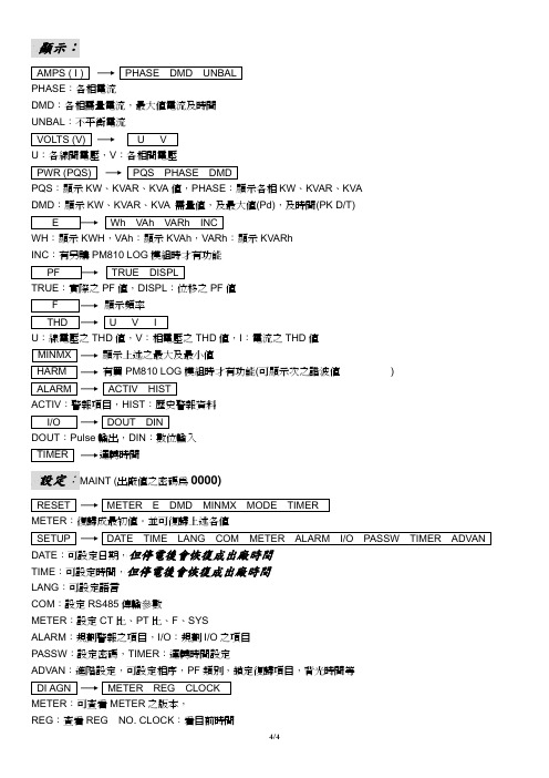
顯示:AMPS ( I ) PHASE DMD UNBALPHASE:各相電流DMD:各相需量電流,最大值電流及時間UNBAL:不平衡電流VOLTS (V) U VU:各線間電壓,V:各相間電壓PWR (PQS) PQS PHASE DMDPQS:顯示KW、KVAR、KVA值,PHASE:顯示各相KW、KVAR、KVADMD:顯示KW、KVAR、KVA 需量值,及最大值(Pd),及時間(PK D/T)E Wh VAh VARh INCWH:顯示KWH,VAh:顯示KVAh,VARh:顯示KVARhINC:有另購PM810 LOG模組時才有功能PF TRUE DISPLTRUE:實際之PF值,DISPL:位移之PF值F 顯示頻率THD U V IU:線電壓之THD值,V:相電壓之THD值,I:電流之THD值MINMX 顯示上述之最大及最小值HARM 有買PM810 LOG模組時才有功能(可 顯示 次之諧波值)ALARM ACTIV HISTACTIV:警報項目,HIST:歷史警報資料I/O DOUT DINDOUT:Pulse輸出,DIN:數位輸入TIMER 運轉時間設定:MAINT (出廠值之密碼為0000)RESET METER E DMD MINMX MODE TIMERMETER:復歸成最初值。
並可復歸上述各值SETUP DATE TIME LANG COM METER ALARM I/O PASSW TIMER ADVAN DATE:可設定日期,但停電後會恢復成出廠時間TIME:可設定時間,但停電後會恢復成出廠時間LANG:可設定語言COM:設定RS485傳輸參數METER:設定CT比、PT比、F、SYSALARM:規劃警報之項目,I/O:規劃I/O之項目PASSW:設定密碼,TIMER:運轉時間設定ADVAN:進階設定,可設定相序,PF類別,鎖定復歸項目,背光時間等DI AGN METER REG CLOCKMETER:可查看METER之版本,REG:查看REG NO. CLOCK:看目前時間4/4。
AMPS安全技术说明书
AMPS化学品安全技术说明书第一部分:化学品及企业标识化学品中文名称:2-丙烯酰胺基-2-甲基丙磺酸化学品英文名称:2-Acrylamido-2- Methylpropanesulfonic Acid简称:AMPS分子式:C7H13NO4S分子量:生产企业名称:巨野县中海化工有限公司地址:山东省巨野县煤化工园区邮编:274932传真号码:企业应急电话:电子邮件地址技术说明书编码:中海01生效日期:2012年10月12日第二部分:成分/组成信息纯品混合物有害物成分浓度CAS No.2-丙烯酰胺基-2-甲基丙磺酸≥99%第三部分:危险性概述危险性类别:第类腐蚀品侵入途径:吸入、食入、接触皮肤健康危害:本品具刺激性。
主要对鼻和上呼吸道有刺激症状等。
接触后主要出现皮肤、粘膜尤其是眼和上呼吸道的刺激症状和体征。
环境危害:该物质对水体和土壤污染。
燃爆危险:遇明火、高热易引起燃烧,放出刺激性气体。
第四部分:急救措施皮肤接触:一旦皮肤接触了AMPS,则应立即用大量的流动清水冲洗至少15分钟。
就医。
眼睛接触:如果眼睛接触了AMPS,立即提起眼睑,用大量流动清水彻底冲洗至少15分钟。
就医。
吸入:迅速脱离现场至空气新鲜处。
保持呼吸道通畅。
食入:饮足量温水,催吐。
就医。
第五部分:消防措施危险特性:在火场高温下,能发生聚合放热有害燃烧产物:二氧化硫灭火方法:用抗溶性泡沫、二氧化碳、干粉、砂土灭火。
灭火注意事项:消防人员必须穿特殊防护服,在掩蔽处操作。
第六部分:泄漏应急处理应急处理:迅速撤离泄漏污染区人员至安全区,并进行隔离,严格限制出入。
切断火源。
建议应急处理人员戴自给正压式呼吸器,穿化学防护服。
尽可能切断泄漏源。
防止流入下水道、排洪沟等限制性空间。
小量泄漏:用砂土或其它不燃材料吸附或吸收。
也可以用大量水冲洗,洗水稀释后放入废水系统。
大量泄漏:构筑围堤或挖坑收容。
用泡沫覆盖,降低蒸气灾害。
用防爆泵转移至槽车或专用收集器内,回收或运至废物处理场所处置。
AMPS说明书(中文)
第三章:材料参数从AMPS的原理为切入点,AMPS是基于对泊松方程,电子和空穴的连续性方程,复合/产生方程的求解来对要设计器件的结构和性能进行模拟的。
那么,求解方程需要哪些参数,我们就要设置哪些参数。
AMPS适用与对半导体(单晶,非晶,多晶),绝缘体,金属的模拟。
3.1:半导体材料的参数【载流子寿命图像】对S-R-H 或B-T-B过程进行模拟(3.1)(3.2)(1)在稳定状态时候,Rn一般等于Rp。
所以只能在满足n-n0=p-p0的时候,这个寿命能同时应用于两种载流子。
用这种方法计算,AMPS提供了一种通过计算△n/R和△p/R的自洽检验(Self-Consistancy-Check:SCC)的方法。
那么,如果你相信线性模型很好地适用于两种载流子,而且存在一个寿命值可以同时适用于两种载流子,那么你就可以通过看AMPS 计算出来的SCC寿命是否相等(和你自己输入的值)来检查结果是否是自洽的。
如果你想要寿命的概念和R的线性化应用于电子,那么你就可以假设方程(3.1)是有效的。
在这种情况下,就不同对空穴进行任何的限制了。
在运行的最后,AMPS将计算SCC的值。
如果你刚开始就是正确的,那么SCC的值会和你输入的值相等。
这是空穴的的SCC是没有意义的。
同样,这个方法适用于空穴。
在不确定电子和空穴的线性模型对某些器件区域是否很好地适用的时候,可以假设线性化的寿命适用于电子和空穴,在运行AMPS,然后检查输出的SCC值,如果相等的话,那么你就可以继续做以后的步骤了。
如果在某些区域,SCC中电子寿命<<空穴寿命,AMPS告诉我们:考虑把线性模型运用于电子会更有意义。
因为这个时候,导带的电子式控制(主导controlling)载流子,因此,你输入的寿命值被重置为电子的寿命。
假如过程出来的SCC 电子寿命>>空穴寿命,情况刚好相反。
(2)用方程(3.1)(3.2)对方程的描述不会涉与到S-R-H复合的细节。
PULSE ZX200 Power Amplifier用户指南说明书
Amplifier care bullet points.
DO …
1.
Read the manual; understand the operation, limitations and safety instructions before using
the product.
2.
Use good quality cables of the correct type, in the correct sockets. Speaker cables should
13) IEC Mains Inlet – Use only the supplied power cord or suitable replacement with the correct fuse rating.
Compliance
This equipment is designed to comply with the following standards:
5.
Checks the mains supply in the venue; use a mains checker.
6.
Ensure your amp, speakers and all cables are free from damage
4Ω 10) Channel B speaker output via binding posts. Minimum speaker impedance 4Ω 11) Channel A speaker output via binding posts. Minimum speaker impedance 4Ω 12) Channel A speaker output via 6.35mm (1/4”) 2-pole jack. Minimum speaker impedance
65amps Ventura Guitar Amplifier用户手册说明书

The Ventura Guitar Amplifier Congratulations on your purchase of the Producer!The Ventura, of our “Working Pro” Red Line is a response to the over-saturation of “Lunch Box” amps in the market that are found lacking in quality for professional players. The Ventura illustrates that a compact, portable amp CAN be combined with high-level, professional functionality. The Ventura is made in 65amps’ factory in North Hollywood utilizing the same high-level materials and engineering experience as always. The Ventura uses a 2-6V6 power section and front end utilizing 65amps’ most popular circuits, The Color channel of the London and the Bump Circuit of the SoHo. This allows the Ventura to create a rich palette of American and British tones all with the signature flair that has made 65amps a major presence on top-level tours and recording studios around the world.***READ BEFORE USING AMP FOR THE FIRST TIME***CAUTION - FOR U.S. OPERATION, SET AC VOLTAGE SELECTOR FOR 120 VOLTS ONLY!Tubes:The Producer tube complement consists of two 6v6 tubes.Channels:The Producer has two channels, The Color Channel and the Bump circuit, totaling to four voices that are all accessible through a standard 2-button foot-switch. Master VoltageOur master voltage emulates the tonal response of a big amp only at low volumes. The “Master Voltage”™ knob reduces the B+ voltage and output in the amp in a unique way that keeps the internal tube relationships perfect while keeping the filament voltage up. After seeing all other power schemes’ shortcomings, we’ve come at this from a different angle and we’re very pleased with the results. Y ou can dial this amp down to 3 watts output WITHOUT losing tone, feel, vocabulary, authority, etc.FX Loop - The passive effects loop comes out on a pair of jacks, allowing the user’s own effects to be added after the preamp stage.Bump ControlThe Bump™ control is a much more effective alterna-tive to traditional channel switching. The Bump™ al-lows the user gain-up and re-slope the amp’s tone stack allowing much more midrange to flow through the circuit; thereby gaining up the entire amp naturally and not inducing false preamp gain that creates fizz and buzz. The end result is the effect of having two amps in one.Tone controls:The Tone control for the channel is passive cut-style. We recommend starting at “10” and backing off. With brighter single-coil guitars, the mid’s will focus really well with the TONE set back around “5 to 8”. ON/Standby - Best to turn the POWER switch on first before the Standby and wait about 10 seconds before turning Standby on. This will prolong tube life. When turning the amp off, turn POWER switch off first. This allows the power to drain out of the amp circuit. Y ou can turn off the Standby switch laterbefore turning the amp back on.CHANNEL FTSW - This is allows you to change channels.SPEAKER OUTPUTS - Two speaker outputs in parallel.IMPEDANCE - All 65 212-Combos and Extension Cabinets are wired for 16-ohms (two 8-ohm speak-ers in series). If using two 16-ohm cabinets, set IMPEDANCE to 8-ohms. Always be sure to match the impedance of this amplifier with the impedance of the speaker cabinet you are using.H.T. (High Tension) FUSE - (500mA Slo-Blo) This fuse is in line with the DC voltage in the amp. When the H.T. FUSE blows, it is typically a sign of a bad power tube.A.C. FUSE - (2A/250V Slo Blo) This fuse is connect-ed to the AC primary side of the Power Transformer. CAUTION - Never use a fuse with a higher amper-age rating.Specifications:Specifications:2x 6V6 power section20 WattsHybrid London Color channel and SoHo gain stage front end. 12AT7 Phase inverterBump that works on both channels = 4 VoicesPassive FX LoopMaster VoltageKnobs = Volume, Tone, Master VoltageSwitches = Manual Channel Switch & Manual Bump Switch Footswitch = Dual button that controls channel and bump Pair with cabinet:IMPORTANT: We recommend a qualified technician for retubing. All tubes use the same size socket, but have very different wiring configurations and volt-ages. Placing the wrong tube in the wrong socket can cause damageto the amplifier and tube.PLEASE READ THE FOLLOWING WARNINGS AND USER ADVICE!• Always make sure the AC Voltage Selector is set for the proper voltage (120 volts in the U.S.) before turn-ing on the amplifier!• Always make sure the amplifier is grounded!(3-prong connector - no ground lifts).• Use only a high quality grounded 3-prong AC power cable with this unit. Always look for breaks or exposed wire and replace if defective.• Never remove the chassis from the cabinet! The amplifier will store high voltages long after the amp has been turned off and disconnected from the AC. Changing tubes does not require any internal adjust-ments. Refer all service to a qualified technician.• Do not expose to excessive humidity, direct sun-light or extreme high or low temperatures. Be certain there is adequate ventilation around the amplifier. Never expose to liquids or excessive dust.More info at 。
艾默生管道工具(上海) 套丝机 中文说明书

套丝机中文操作手册艾默生管道工具(上海)有限公司目录机器型号和序列号记录表格 (3)安全须知 (4)工作场所安全注意事项 (4)用电安全 (4)个人安全注意事项 (5)工具的使用与保养 (5)服务 (5)其它安全注意事项脚踏开关的使用安全 (5)套丝机使用安全 (6)产品概述、技术参数与标准配置产品概述 (6)技术参数 (6)标准配置 (7)附件 (7)牙模头和板牙 (7)机器安装安装支架 (9)安装到通用支架 (9)安装到1406支架 (10)安装油盘盖 (10)安装到工作台上 (11)用1406搬运套丝机 (11)用提升设备、牵引设备搬运机器 (11)机器检查 (11)机器和工作区域设置 (13)套丝操作步骤安装管子 (14)用364割刀切割管子 (14)344铰刀铰孔 (15)动力套丝 (16)拆下管子 (12)安装板牙到快开牙模头 (17)安装板牙到自开牙模头 (17)安装板牙半自动牙模头 (18)检查螺纹 (19)819短管工具安装短管工具 (20)短管工具使用 (20)使用齿轮套丝器操作步骤套丝尺寸调整步骤 (21)安装141齿轮套丝器 (22)使用840万向驱动轴来安装141和161齿轮套丝器 (22)套丝 (23)821割刀和822适配器 (23)左旋套丝 (23)附件 (24)保养指导油路系统维护 (25)润滑 (25)卡爪更换 (25)套丝塑料管更换卡爪 (25)机器存放要求 (25)维修与服务 (26)线路图 (26)终身质保条款........................................................................................................................封底1822-I 型套丝机1822-I 型套丝机在下面空格内记下产品序列号,并妥善保存写有产品序列号的铭牌。
序列号安全须知警告!请仔细阅读所有的安全注意事项和安全指导。
BehringerVAmp2.0中文说明书

GUITAR vamp2.0中文说明书1、介绍恭喜!阁下购买的V-AMP2为V-AMP虚拟吉它扩音器的改良产品。
我们对其进行改进的最终目的是通过“物理模拟”并结合最新的DSP效果器方式以产生出值得信赖的经典扩音器的音色。
与其上一代产品--V-AMP相比,V-AMP2具有许多优势:被模拟的扩音器数量增加了一倍;五个可进行全局调整的操作模式;由于带有前级旁路(P reamp Bypass),你还可以将该设备单纯作为的效果器来使用。
我们再次直面研发产品带来的挑战。
当然它仍有可能成为未来一段时间人们的话题。
V-AMP2是一款多功能的产品,它既可以在绝不造成任何信号传输问题的情况下,为您带来32款值得信赖的、甚至是特殊的扩音器的音色,还可以为您提供由多效果处理器技术带来的各种声音。
简而言之,V-AMP2给您的是一个声音工具,里面包含了各种当今音乐人梦寐以求的元素。
BEHRINGER是一家由从事专业录音棚技术发展而来的公司。
多年以来,我们已经成功地开发了多种用于录音棚及演出现场的产品,包括麦克风及各类标准机架设备(如压缩器、增强器、噪音门、电子管处理器、耳机放大器、数字效果设备及DI 盒等)、监听器、调音台以及专业现场、录音棚混音器。
我们已将所掌握的全部技术融入V-AMP2中。
灵活性是音乐领域中至关重要的一环。
一个现代吉它手不仅需要演奏多种音色,还需要有适应不同演奏环境(家庭录音、录音棚、现场演出)的能力。
因此,庞大的扩音器堆阵已经成为过去。
V-AMP2融尽可能多的功能于一身,而且设置及携带非常方便,同时很容易就可以掌握。
置的EPROM很方便进行替换,从而使得V-AMP2可以引领时代。
也就是说我们将听取您的建议,并且不断地对新的算法进行研究。
然后放在互联网上供您免费下载,这样即使是在将来,V-AMP2也一样不会落伍。
百闻不如一试。
接下来您将体验的新一代虚拟吉它扩音器,如下特点令人叹为观止:出位的音色足以令所有的传统吉它扩音器望尘莫及;完美的电子管音色模拟且避免了一般电子管扩音器的通病(使用寿命短、发热量大、过于灵敏);最新的DSP技术带来了从古典到现代的大量效果音色;构造坚固,可以适应哪怕是最恶劣的环境。
7 Amps SOLAR CHARGE CONTROLLER – 用户指南说明书

7 Amps SOLAR CHARGE CONTROLLER –USER’S MANUALSPECIFICATIONSCut-in Voltage: 13VoltsCut-Out Voltage: 14.2 VoltsMax. Load: 105 Watts/ 7 AmpsINSTALLATIONConnect to Battery:Attach the Solar Charge Controller positive (+) wire to the positive (+) battery terminal. Then connect the Solar Charge Controller negative (-) wire to the negative (-) battery terminal.WARNING: The alligator clips MUST be placed on to the battery in the aforementioned order—wrong connections may cause sparking or explosion.Connect to Solar Panel:Option 1Strip the solar panel wires. Connect positive (+) wire from the solar panel to the positive (+) of the charge controller and the negative (-) wire from the solar panel to the negative (-) of the charge controller. Ensure the connections are secure.Option 2Some panels may include a quick connect for use with the Solar Charge Controller. If included, connect positive to positive and negative to negative of charge controller. Ensure connections are secure.OPERATIONThe Green “Charged” light indicates a full-charged battery. When the battery reaches 14.2 V, the Solar Charge Controller will cut out voltage thereby ensuring no overcharging. The yellow “Charging” light indicates a battery that is being charged. When the battery reaches 13 V, the Battery Charge Controller will cut-in and begin charging.NOTES•The Solar Charge Controller should be placed within 5 feet of the battery in a dry well ventilated area.•This Solar Charge Controller can support up to 105 watts of solar power. It is not advisable to use with greater wattage.•All connections should be in parallel to ensure a 12 Volt system.•It is normal for both lights to flicker on and off during normal operation. The Battery Charge Controller should be placed within 5’ of the battery in a dry, well-ventilated area. This Battery Charge Controller can support up to 105 W and up to 7 A of array current. All connections should be parallel to ensure 12 V system (positive to positive and negative to negative).FAQ1. How many panels can I connect to my 7 Amp Solar Charge Controller?You can connect up to 105 Watts of Solar Power to the 7 Amp Solar Charge Controller. Panels should be connected in parallel – positive to positive, negative to negative.2. When will the Charged Indication light (green) light up?The charged indication green light will light up when the battery voltage reaches 14.2 Volts and the SCC will prevent the solar panels from overcharging the battery. It is normal for the SCC LED to light on and off as the battery voltage cuts in and out.GENERAL TESTING PROTOCOLAlways test outdoors under optimal sunlightTest Solar Panel for VoltageConnect Voltmeter to the panel separately from the charge controller and observe Open Voltage. Open Voltage can range from 16 Volts to 24 Volts.Test Connection to Charge Controller for Voltage.Reconnect solar panel, and connect to charge controller as per instructions. Measure the Open Circuit Voltage at the battery side of the charge controller. Open circuit voltage should read 5-10% lower than without charge controller. Open circuit measurement will read between 15 and 23.5.Connect charge controller to batteryFirst, disconnect solar panels and connect charge controller to battery. Always connect charge controller to battery first and remove last. Observe polarity – positive to positive and negative to negative.Reconnect Solar Panels to Charge ControllerIf battery voltage is 14.2 or higher, the GREEN light should be on. If battery voltage is between 13 and 14.2, the YELLOW LED should be on. If battery voltage is 13 or lower, the YELLOW LED should be on.If all testing results within the above indicated ranges, solar system is in acceptable range. If Voltage readings indicate lower ranges, repeat above connections and retest. Finally, it is common to have 12V Battery issues such as dead cells or non-rechargeable battery problems.WarrantyThis product is covered by a 1 year limited warranty. N’Power Product's will warrant to the original purchaser that this product is free from defects in materials and workmanship for the period of one year from date of purchase.To obtain warranty service please contact N’Power Products for further instruction, at 1-800-222-5381. Proof of purchase including date, and an explanation of complaint is required for warranty service. Distributed by Northern Tool + Equipment Company 2800 South cross Drive Burnsville, MN 55306。
百灵达中文说明书
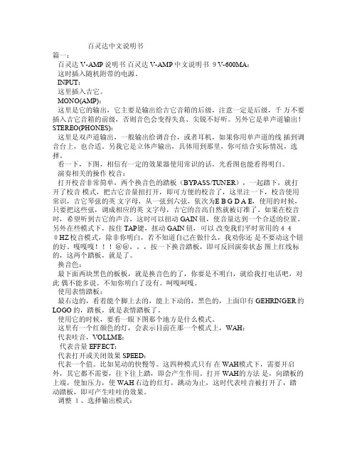
百灵达中文说明书篇一:百灵达V-AMP说明书百灵达V-AMP中文说明书9V-600MA:这时插入随机附带的电源。
INPU T:这里插入吉它。
MO NO(AM P):这里是它的输出,它主要是输出给吉它音箱的后级,注意一定是后级,千万不要插入吉它音箱的前级,否则音色会变得失真、尖锐不好听。
另外它是单声道输出!STERE O(PHO NES):这里是双声道输出,一般输出给调音台,或者耳机,如果你用单声道的线插到调音台上,也合适。
另我它是立体声输出,具体用到那里,你可结合实际情况,选择。
看一下,下图,相信有一定的效果器使用常识的话,光看图也能看得明白。
演奏相关的操作校音:打开校音非常简单,两个换音色的踏板(BY PASS/TUNER),一起踏下,就打开了校音模式,把吉它音量扭打开,即可方便的校音了,这里注一下,校音使用常识,吉它琴弦的英文字母,从一弦到六弦,依次为E B GD A E,使用的时候,只要把这些弦,调成相应的英文字母,吉它的音高自然就被订准了。
如果在校音时,希望听到吉它的声音,这时可以扭动 GAI N钮,使音量达到一个合适的位置。
另外在些模式下,按住TAP键,扭动GA IN钮,可以改变我们平时常用的440H Z校音模式,除非你明白,若不知道自己在做什么,我劝你还是不要动这个钮的好。
嘎嘎嘎@@,,,按一下换音踏板,即可反回演奏状态图上红线标的,这两个踏板,就是了。
换音色:最下面两块黑色的板板,就是换音色的了,你要是不明白,就给我打电话吧,对此偶不能多说。
不知你明白了没有。
呵嘎呵嘎。
使用表情踏板:最右边的,看着能个脚上去的,能上下动的,黑色的,上面印有GEH RINGE R的LOG O的,踏板,就是表情踏板了。
梅达焊接控制器说明中文版
. .MedWeld6000 中频控制器说明书目录第1章:系统概述 (3)1.1. 简介 (3)1.2. 机器人应用 (3)1.3. 焊接控制器内部 (4)1.4. 规格参数 (4)第2章:控制器开箱 (7)2.1. 检查 (7)2.2. 起吊和移动焊接控制器 (7)2.3. 零部件的破损,遗失 (8)第3章:安全与警告 (10)3.1. 上锁 (10)3.2. 文档中的符号 (10)3.3. MedWeld 6000焊接柜安全问题 (11)第4章:焊接控制器安装 (13)4.1. 安装列表 (13)4.2. 机械安装 (15)4.3. 电气安装 (18)4.4. 程序和软件设置 (19)第5章: 通讯设置 (21)5.1. 关于MedWeld 6000 通讯 (21)5.2. DeviceNet 设置 (22)5.3. Ethernet/IP 设置 (23)5.4. 6000系列处理器LED 指示灯 (24)第6章:焊接程序 (25)6.1. 关于焊接程序 (25)6.2. 编辑一个程序 (28)6.3. 默认程序 (30)第7章:设置参数 (33)7.1. 设置参数 (33)第8章:递增器 (45)8.1. 递增器介绍 (45)8.2. 递增器组 (46)8.3. 在一个焊接程序中打开一个递增器 (47)8.4. 电极修磨 (48)第9章:先进特点 (50)9.1. C系数 (50)9.2. 自动电流补偿焊接 (51)9.3. 自动电压补偿焊接 (52)第10章:故障及诊断 (54)10.1. 故障列表 (54)第11章:维护保养 (63)11.1. 保养明细表 (63)11.2. 备件清单 (63)参考A:I/O列表 (65)1. 灵活的I/O (65)2. 完整的I/O列表(EIP和Fieldbus) (67)3. IO定义 (70)参考B:焊接功能项列表 (76)1. 完整的焊接功能项列表 (76)2. 延时功能项 (80)3. 焊接功能项 (80)4. 坡度功能项 (82)5. I/O功能项 (83)6. 延伸功能项 (84)7. 特殊功能项 (85)第1章:系统概述1.1. 简介MedWeld6000是美国WTC公司最新推出的逆变焊接控制平台。
M-800A纯晶体A音频放大器用户手册说明书

4
Front Panel Controls
1.
POWER INDICATOR; LED blinks
gently initially to show that it is warming
up, will shine constantly once the M-
800A is fully operational. Yellow in
8.
BTL (Mono) INDICATOR Blue LED
shows that the Bridged Monaural output
is engaged.
5
Rear Panel Controls
9.
POWER SOCKET (AC) Connect the M-800A power cord to a live AC outlet.
IMPORTANT SAFETY INSTRUCTIONS!
PLEASE READ THEM BEFORE OPERATING THIS EQUIPMENT.
1. Read these instructions. 2. Heed all warnings. 3. Follow all instructions. 4. Do not use this apparatus near water. 5. Clean only with a dry cloth. 6. Do not block any ventilation openings. Install
Please take a short time to read the information in this manual. We want you to be as familiar as possible with all the features and functions of your new Luxman.
Waves GTR Amp 用户手册说明书

Waves GTR Amp User GuideTABLE OF CONTENTSCHAPTER 1 – INTRODUCTION (3)1.1 W ELCOME ............................................................................................... 3 1.2 P RODUCT O VERVIEW .................................................................................. 3 1.3 C OMPONENTS .......................................................................................... 4 CHAPTER 2 – QUICKSTART GUIDE. (5)CHAPTER 3 – CONTROLS AND INTERFACE (6)3.1 A MP T YPES ............................................................................................. 6 Clean..................................................................................................... 6 Drive ..................................................................................................... 7 High Gain............................................................................................... 8 Neil Citron.............................................................................................. 9 Bass.....................................................................................................10 3.2 A MP C ONTROLS .......................................................................................11 3.3 C ABINETS AND M ICROPHONES ......................................................................12 Cabinets................................................................................................12 Bass Cabinets ........................................................................................13 Microphones ..........................................................................................13 3.4 C ABINET AND M ICROPHONE C ONTROLS ............................................................14 3.5 A MP C OMPONENTS ....................................................................................16 APPENDIX .. (19)1.4 W AVE S YSTEM T OOLBAR (4)3.6 HD (High Definition) O PTION (18)Chapter 1 – Introduction1.1 WelcomeThank you for choosing Waves! In order to get the most out of your new Waves plugin, please take a moment to read this user guide.To install software and manage your licenses, you need to have a free Waves account. Sign up at . With a Waves account you can keep track of your products, renew your Waves Update Plan, participate in bonus programs, and keep up to date with important information.We suggest that you become familiar with the Waves Support pages: /support. There are technical articles about installation, troubleshooting, specifications, and more. Plus, you’ll find company contact information and Waves Support news.1.2 Product OverviewWaves Amp is a primary component of GTR, which features an exceptional selection of virtual amplifiers, cabinets, and microphones. While GTR was designed to be used with electric guitar, it’s also a powerful set of tools for processing and re-amping drum or vocal tracks.Each amp has two main sections:•Amp Type – With controls for amp selection and tone adjustment.•Cabinet & Mic – With controls for cabinet selection, microphone selection, and microphone position.1.3 ComponentsWaveShell technology enables us to split Waves processors into smaller plug-ins, which we call components. Having a choice of components for a particular processor gives you the flexibility to choose the configuration best suited to your material.Waves GTR Amp includes Mono, Mono Dual Cabinet, Mono-to-Stereo, and Stereo configurations. The Mono Dual Cab, Mono-to-Stereo, and Stereo components can each accommodate one amplifier with two cabinets. In Mono-to-Stereo and Stereo configurations, the output of each cabinet can be panned independently.1.4WaveSystem ToolbarUse the bar at the top of the plugin to save and load presets, compare settings, undo and redo steps, and resize the plugin. To learn more, click the icon at the upper-right corner of the window and open the WaveSystem Guide.Chapter 2 – Quickstart Guide•When you open the Waves Amp plug-in on a track insert, it’s ready to go with the default Clean amp.•Use the Drive control to crank up the gain for more intensity without changing your output volume.•For a more distorted tone, choose an amp with more Drive from the Amp Type menu. Amps are sorted in an escalating gainorder.•Once you’ve selected your amplifier, open up a post-amp PedalBoard. Reverb, Vibrolo, Delay, EQ, and Compression allwork well as post-amp effects.•Here’s an example of a possible full setup:Stomp 6 Mono-to-Stereo PedalBoard with its default preset,followed by a Stereo Amp, followed by a Stomp 2 StereoPedalBoard with Vibrolo and Spring Reverb Stomps.Chapter 3 – Controls and Interface 3.1 Amp TypesSelect the amp model using the Amp Types menu. Amps are sorted into groups by application or drive rating. Each group has a unique skin.C LEAN amps are displayed with a golden panel and tweed skin.•Direct Full-frequency, transparent tone•Clean Based on a 1959 tweed Fender® Bassman®.•Warm Based on a boutique amp from Paul Reed Smith's private collection.•Punchy Based on a 100W Marshall® head•Sweet Based on a 1968 Gibson® SkylarkD RIVE amps are displayed with a blue panel and gold threaded cloth skin.•Cream Based on a 1966 Ampeg® Gemini II•Edgy Based on a 1980 Vox® AC-30 TB-2•Drive Based on a 1964 blackface Fender® Super Reverb®•Overdrive Based on a1980 Marshall® JMP•Scream Based on a custom amp from Paul Reed Smith's private collectionH IGH G AIN amps are displayed with a red wine panel and treadmillskin.•Crunch Based on a custom Garcia™ from Paul Reed Smith’s personal collection•Crush Based on a modified Marshall® MK2 50W stack head•Scorch Based on a boutique amp from Paul Reed Smith's private collection•Inferno A virtual model with super-high distortion and extremely fast cleanup•Monster Based on a Marshall® 100W head•Hot Based on a Koch® Combo•Modern Based on a Mesa® Dual Rectifier® Solo head•Shredder Based on a Marshall® JMP1 preamp•Supernatural Based on a boutique amp from Paul Reed Smith's private collectionN EIL C ITRON amps are displayed with a purple velvet skin.•Legatron Clean Based on a customized Carvin® Legacy•Legatron Crunch Based on a customized Carvin® Legacy•Thermitron Clean Based on an Ibanez® TN120 Thermion•Thermitron Crunch Based on an Ibanez® TN120 Thermion•Plexitron Lite Based on a modified 60s 100W Marshall® Plexi •Plexitron Crunch Based on a modified 60s 100W Marshall® PlexiB ASS amps are displayed with a silver panel and grill skin.•Directube Based on a Countryman® DI into a V72 preamp •Activator Based on a Sadowsky® preamp•SolidState Based on a Hartke® 3500•Mo'Town Based on a fliptop Ampeg® B15-N tube amplifier •SuperTube Based on the Ampeg® SVT•Thunder Based on a David Eden® World Tour 800•OverBass Based on a Mesa/Boogie® 400+3.2 Amp ControlsAll Amps feature Drive, Bass, Mid, Treble, and Presence controls, whose response curves are tailored to complement the specific amp type.D RIVE controls the drive level range of +12dB to -12dBfs, with a default of 0dB.Range:0 to 10Default: 5B ASS controls low frequency equalization cut/boost.Range:-5 to +5Default: 0M ID controls midrange frequency equalization cut/boost. Range:-5 to +5Default: 0T REBLE controls high frequency equalization cut/boost.Range:-5 to +5Default: 0P RESENCE controls high frequency equalization cut/boost. Range:0 to 10Default: 0D IRECT when Bass Amp types are selected the Presence control is replaced by the Direct control, which controls the amount of direct mixed with the processed signal.Range: 0 to 10Default: 0A MP controls Amp activation/bypass. When set to Bypass, input is routed directly to the cabinet and mic.Range: On/BypassDefault: OnT YPE controls Amp selection.Range: Direct to OverBassDefault: Clean3.3 Cabinets and MicrophonesCabinets and microphones are selected by using the appropriate menu selector.Toggle through them by clicking on the text bar, or click on the arrow to the right of the text bar to display a drop-down list.Each cabinet offers a choice of 6 microphones, which may be positioned either on or off axis.Please note: “No Cabinet” uses neither a cabinet nor microphone, and is the default choice for the Direct Amp.C ABINETSSelect from 22 speaker cabinets.• 4 x 12” Standard Based on a Marshall® 1960a• 4 x 12” Vintage Based on Marshall® 1960ax with Celestion®G12 Greenbacks• 4 x 12” Britt Based on an Orange® PPC412 with Celestion®Vintage30s• 4 x 12” Inferno Based on a virtual cabinet• 2 x 12” ClosedBack Based on a Marshall® 1936 cabinet with Celestion® G12 Greenbacks• 2 x 12” OpenBack Based on a Vox® AC-30 Celestion® Alnico Blue• 4 x 10” OpenBack Based on a Fender® Super Reverb®Blackface 1968 with CTS alnico magnet speakers•12” OpenBack Based on a Mesa/Boogie® Mark IV with an Electro-Voice® speaker•15” ClosedBack Based on a 1960’s Fender® Showman cabinet •Acme 12” Custom Based on a custom cabinet by Ted Jensen of Sterling Sound•Acme 2 x 10” Cabinet Based on a 1962 Vox® cabinet•Acme 8” OpenBack Based on a 1968 Gibson® Skylark•Acme 4 x 12” Cab Based on a 1970’s Hiwatt® cabinet•Acme 12” OpenBack Based on a mid ‘60s Ampeg Gemini cabinet•Acme 2 x 10” OpenBack Based on a 1965 Fender® Vibrolux®Reverb Blackface cabinet•Acme Case Speaker Based on a late ‘60s Silvertone® case with built-in speakerB ASSC ABINETS•Bass 8 x 10” Pro Based on an Ampeg® SVT810AV•Bass 6 x 10”Based on an Ampeg® SVT610HL•Bass 15”Based on a late ‘60s Fender® Bassman®•Bass 15” Fliptop Based on an Ampeg® B15N•Bass E15 15” + (4 x 10”) Based on David Eden® cabinets•Bass M1516 10” + 15” + (2 x 6”)Based on a Mesa/Boogie®1516M ICROPHONESSelect from different microphones, recorded in different positions.•Dyn 409 Based on a Sennheiser® Echolette 409 (dynamic)•Dyn 421 Based on a Sennheiser® MD-421 II (dynamic)•Dyn 57 Based on a Shure® SM57 (dynamic)•Ribb 84 Based on a AEA® R84 (ribbon)•Ribb 44 Based on a RCA® 44 (ribbon)•Dyn RE20 Based on a Electro-Voice® RE20 (dynamic)•Cond VM1 Based on a Brauner VM1® (condenser)Bass Mics•Coil 88 Based on a Beyer® M88 (dynamic moving coil)•Dyn Based on a RE20 Electro Voice® RE20 (dynamic)•Dyn 57 Based on a Shure® SM57 (dynamic)•Cond 87 Based on a Neumann® U87 (condenser)•Cond GR Based on a Manley® Gold Reference (condenser)•Ribb 122 Based on a Royer® 122 (ribbon)3.4 Cabinet and Microphone ControlsV OL controls Cab/Mic volume.Range: 0 to 10Default: 5P HASE controls Cab/Mic polarity (DualCabinet only).Range: Up/Down (Up = natural phase, Down = inverted phase) Default: UpP AN controls cabinet positions within the stereo field. (Mono-to-Stereo and Stereo amps only).Range: -100 to +100Default: 0D ELAY controls the amount of delay applied to the cabinet's output. Range: 0 – 100Default: 0M ASTER V OLUME controls overall output gain. Output meter includes red light clip indicator.Range: 0 to 10Default: 53.5 Amp ComponentsMono AmpThe Mono Amp is the least CPU-intensive of the Amp components. It inputs and outputs a Mono signal, running the output through a single Amp module and then into a single cabinet/microphone filter.Mono DualCabThe Mono DualCab amp is similar to the Mono amp in that it inputs and outputs a Mono signal. The DualCab configuration lets you play the Amp’s sound through two separate cabinets. This allows for combinations such as loading the same cabinet with different microphones or using two different cabinets with the same mic.The outputs of the two sources are then mixed together to a single output. Each cabinet has a phase switch and a volume control. Please note: Selecting the same cabinet and microphone for both cabinets will result in a normal Mono single cabinet sound. In this case, inverting the phase of one of the two cabinets will result in a silent output.Mono-to-Stereo and StereoMono-to-Stereo StereoThe Mono-to-Stereo and Stereo Amps share the same controls and graphic user interface, but their input and processing specifications are different.Mono-to-Stereo is very similar to the Mono DualCab component, but outputs a Stereo signal. Rather than adding each cabinet’s output to a single path you can pan them to create a Stereo image from the Mono input.The Stereo Amp component is actually a dual-Mono configuration which takes a Stereo input and outputs Stereo. The Left input goes through the Amp type to cabinet 1 and the Right input goes to cabinet 2.The Pan control can be used to limit the Stereo image width, collapse the Stereo input to a Mono output, or swap the channel outputs by hard panning them in opposite directions.3.6 HD (High Definition) OptionThe HD Option control is located at the top right of the plug-in's toolbar. It is off by default.When running GTR at 44.1 or 48kHz, you have the option of doubling the internal amplifier sampling rate. HD offers fewer aliasing artifacts, and is especially useful for High Gain models.Please note: Engaging the HD option will increase your CPU load. When running at HD sample rates 88.2 or 96kHz the HD option is not available.Important Note for Pro Tools TDM UsersThe HD option as described above applies only to the GTR Amp RTAS plug-in. Under TDM, the GTR Amp with HD is offered as a separate mono-only plug-in.AppendixAll product names and trademarks are the property of their respective owners, which are in no way associated or affiliated with Waves. Product names are used solely for the purpose of identifying the specific products that were studied during Waves’ sound modeling process and for describing certain types of tones produced with Waves’ proprietary algorithms. Use of these names does not imply any co-operation or endorsement.Gibson® is a trademark of Gibson Guitar Corp.Mesa/Boogie® and Rectifier¨ are trademarks of Mesa/Boogie Ltd. Silvertone® is a trademark of Samick Music CorporationMarshall® is a registered trademark of Marshall Amplification Plc.Fender®, Super Reverb®, and Bassman® are registered trademarks of Fender Musical Instruments Corporation.Ampeg® is a registered trademark of St. Louis Music, Inc.Koch® is a registered trademark of Koch Guitar ElectronicsVox® is a registered trademark of Korg Europe Ltd.Sadowsky® is a registered trademark of Sadowsky Guitars Ltd. Hartke® is registered trademark of Samson Technologies CorpDavid Eden® is a registered trademark of Eden ElectronicsCountryman® is a registered trademark of Countryman Associates Inc.Neumann® is a registered trademark of Georg Neumann GmbHShure® is a registered trademark of Shure IncorporatedBrauner® is a registered trademark of Brauner MicrophonesAKG® is a registered trademark of AKG Acoustics, Austria, A Harman International CompanySennheiser® is a registered trademark of Sennheiser Electronic GmbH & Co. KGRCA® is a registered trademark of Thomson SACelestion® is a registered trademark of KH Technology Corporation Hiwatt® is a registered trademark of Fernandes Company Ltd.Royer® is a registered trademark of Royer Labs。
AMP Mini CT 连接器系列说明书
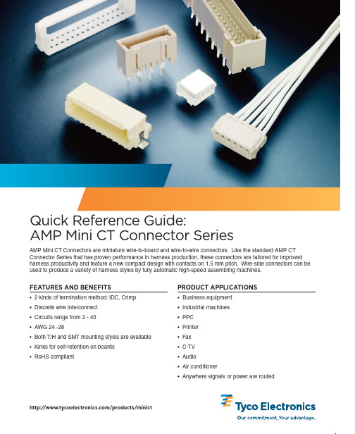
2AMP Mini CT Connector SeriesDUAL ROW ASSEMBLIESPHOTO KEY/products/minictAll part numbers are RoHS compliant.Requires a holder to be used along with a single row housing.Photos correspond to part numbers on page 3.Shows an unstripped wire inserted into an MT Housing.Shows a contact crimped onto a stripped wire to be inserted into a crimp housing.MT Mini CT ConnectorCrimp Mini CT ConnectorCrimp Mini CT Contact MASS TERMINATION (MT) VS. CRIMP POKEMTCrimp Poke Time savingsCost effective Preloaded IDC contacts Flexibility (AWG)AutomationManual laborMates w/ same headers as Crimp Mates w/ same headers as MT35392335390835390763.67.47.47.4688Receptacle Connector (single)Single Row HousingDual Row HousingHolderPost HeaderBoss663.63.6AMP Mini CT HousingAMP Mini CT HousingAMP Mini CT ContactAMP Mini CT HeaderAMP Mini CT HolderAMP Mini CT HeaderAMP Mini CT HeaderAMP Mini CT HeaderAMP Mini CT HeaderAMP Mini CT Panel MountPhoto APhoto EPhoto IPhoto JPhoto FPhoto GPhoto HPhoto BPhoto CPhoto DAMP Mini CT Connector Series3PCB CONNECTORSCABLE SIDE CONNECTORSHOW TO SELECT AN AMP MINI CT CONNECTOR PART NUMBERMT CONNECTORSCrimp Type Connectors/products/minictAll part numbers are RoHS compliant.CONTACTS SINGLE ROW POST HEADER ASSEMBLIES BOARD-MOUNT SINGLE ROW POST HEADER ASSEMBLIES PANEL-MOUNT DUAL ROW HEADERS DUAL ROW POST HEADER ASSEMBLIES - BOARD-MOUNT DUAL ROW POST HEADER ASSEMBLIES - PANEL-MOUNT RATINGSRECEPTACLE CONNECTORS (WIRE APPLICATION)CRIMP TYPE HOUSING Mating Part Numbers: 292206; 292207; 292227; 292228; 292239; 292231; 292215; 292208; 292216Specifications : BMating Part Numbers: (MT) 353293 or (Crimp) 353908 w/ 353907-1 or 353918-1Specifications : A, X353294 w/ 2 x MT or 2 x Crimp Single Row HeadersSpecifications : A, C, X353294 w/ 2 x MT or 2 x Crimp Single Row HeadersSpecifications : C, XMating Part Numbers: 2 x (MT) 353293 or 2 x (Crimp) 353908 w/ 353907-1 or 353918-1Specifications : C, XSpecifications : A, XPart Number Receptacle Contact Specifications 353907-1Reel - AWG: 26-28B, Y 353918-1Loose Piece - AWG 24-28 (See Photo B on page 2)B, YVoltageCurrent (Amps)TemperatureProduct Specifications AWG 2224262830A 108-6001850 V (AC/DC)AMPS 21-30 to 105°CB 108-6002550 V (AC/DC)AMPS 22-30 to 105°C C 108-5225250 V ACAMPS 33221-65 to 105°CMating Part Numbers: (MT) 353293 or (Crimp) 353908 w/ 353907-1 or 353918-1Specifications: A, XApplication Specifications X 114-5223Y 114-5245The charts on this page highlight the relationship between the number of contacts (positions) to the part number. Please see the sample chart below that was designed to help you select the correct part number for your needs. For single digit position to dash numbers, attach the digit to the end of the base number. For double digit position to dash numbers, attach the first digit to the front of the part number, add a dash and the base part number, then follow the base part number with a dash and the second digit.© 2009 Tyco Electronics Corporation. All Rights Reserved.AMP , DECAM, TE LOGO and TYCO ELECTRONICS are trademarks. Other products, logos and company names mentioned herein may be trademarks of their respective owners.Dimensions are in millimeters with inches (if shown) in brackets. Specifications subject to change.For more information, contact your Tyco Electronics sales engineer at the numbers listed below, or visit our Website at: . USA: 1-800-522-6752S. America: 55-11-2103-6000 France: 33-1-3420-8686Canada: 1-905-470-4425Germany: 49-6251-133-1999 Netherlands: 31-73-6246-999Mexico & C. America: 52-55-1106-0814UK: 31-73-6246-431 China: 86-400-820-60156-1773454-5–1K–CIS–AH–04/09DisclaimerWhile Tyco Electronics has made every reasonable effort to ensure the accuracy of the information in this catalog,Tyco Electronics does not guarantee that it is error-free, nor does Tyco Electronics make any other representation,warranty or guarantee that the information is accurate, correct, reliable or current.Tyco Electronics reserves the right to make any adjustments to the information contained herein at any time without notice. Tyco Electronics expressly disclaims all implied warranties regarding the information contained herein,including, but not limited to, any implied warranties of merchantability or fitness for a particular purpose. The dimensions in this catalog are for referencepurposes only and are subject to change without notice.Specifications are subject to change without notice. Please consult Tyco Electronics for the latest dimensions and design specifications.Restriction on the use of Hazardous Substances (RoHS)At Tyco Electronics, we’re ready to support your RoHS requirements. We’ve assessed more than 1.5 million end items/components for RoHS compliance, and issued new part numbers where any change was required to eliminate the restricted materials. Part numbers in this catalog are identified as:RoHS Compliant — Part numbers in this catalog are RoHS Compliant, unless marked otherwise. These products comply with European Union Directive 2002/95/EC as amended 1 January 2006 that restricts the use of lead, mercury, cadmium, hexavalent chromium, PBB, and PBDE in certain electrical and electronic products sold into the EU as of 1 July 2006.NOTE:For purposes of this Catalog, included within the definition of RoHS Compliant are products that are clearly “Out of Scope” of the RoHS Directive such as hand tools and other non-electrical accessories.NOTE:Information regarding RoHS compliance is provided based on reasonable inquiry of our suppliers and represents our current actual knowledge based on the information provided by our suppliers. This information is subject to change. For latest compliance status, refer to our website referenced at right.Getting the Information You NeedOur comprehensive on-line RoHS Customer Support Center provides a forum to answer your questions and support your RoHS needs. A RoHS FAQ (Frequently Asked Questions) is available with links to more detailed information. You can also submit RoHS questions and receive a response within 24 hours during a normal work week. The Support Center also provides:Cross-Reference from Non-compliant to Compliant ProductsAbility to browse RoHS Compliant Products in our on-line catalogDownloadable Technical Data CustomerInformation Presentation More detailed information regarding the definitions used aboveSo whatever your questions when it comes to RoHS, we’ve got the answers at /leadfreeRoHSCustomer Support CenterQUESTIONS TO ASK AT DESIGN IN•What wire gauge will you be using?More flexibility with AWG when using Crimp (24~28 AWG) vs.MT (26~28 AWG).•Are the connectors available for IDC?Yes, we offer an MT version that is preloaded with IDC contacts.•Is your process automated?MT housings are suitable for automated processes.•What current, voltage and operating temperature is required?Please see product specification information on the charts on page 3 of this document.•Which is a more standard header, with or without a locating boss?The most standard headers tend to have a locating boss as it makes it easier for the customer to align the connector onto their board.•What special retention mechanisms are available to provide stability?Tyco Electronic's T/H headers have a staggered tine design to provide stability.•What are my tooling options?Tyco Electronics offers comprehensive tooling optionsincluding manual pistol-grips, manual mini-press, pneumatic mini-press, semi-auto DECAM and an automatic DECAM tool.For more information, please visit .YOU ARE HERE (E-CATALOG)Product Overview Page/products/minict Breakdown From Main PageAMP Mini CT Connector Series。
HeadAmp6 PROFESSIONAL六通道头戴耳机放大器操作手册说明书

HeadAmp6 PROFESSIONAL SIX CHANNEL HEADPHONE AMPLIFIER OPERATION MANUALIMPORTANT SAFETY INSTRUCTIONS – READ FIRST This symbol, wherever it appears, This symbol, wherever it appears, alerts alerts you to the presence of uninsulated you to important operating and maintenance dangerous voltage inside the enclosure. Voltage instructions in the accompanying literature.that may be sufficient to constitute a risk of shock. Please read manual.Read Instructions:Retain these safety and operating instructions for future reference. Heed all warnings printed here and on the equipment. Follow the operating instructions printed in this user guide.Do Not Open:There are no user serviceable parts inside. Refer any service work to qualified technical personnel only.Power Sources:Only connect the unit to mains power of the type marked on the rear panel. The power source must provide a good ground connection.Power Cord:Use the power cord with sealed mains plug appropriate for your local mains supply as provided with the equipment. If the provided plug does not fit into your outlet consult your service agent. Route the power cord so that it is not likely to be walked on, stretched or pinched by items placed upon or against.Grounding:Do not defeat the grounding and polarization means of the power cord plug. Do not remove or tamper with the ground connection on the power cord.Ventilation:Do not obstruct the ventilation slots or position the unit where the air required for ventilation is impeded. If the unit is to be operated in a rack, case or other furniture, ensure that it is constructed to allow adequate ventilation.Moisture:To reduce the risk of fire or electrical shock do not expose the unit to rain, moisture or use in damp or wet conditions. Do not place a container of liquid on it, which may spill into any openings.Heat:Do not locate the unit in a place close to excessive heat or direct sunlight, as this could be a fire hazard. Locate the unit away from any equipment, which produces heat such as: power supplies, power amplifiers and heaters. Environment:Protect from excessive dirt, dust, heat, and vibration when operating and storing. Avoid tobacco ash, drink spillage and smoke, especially that associated with smoke machines.Handling:To prevent damage to the controls and cosmetics avoid rough handling and excessive vibration. Protect the controls from damage during transit. Use adequate padding if you need to ship the unit. To avoid injury to yourself or damage to the equipment take care when lifting, moving or carrying the unit.Servicing:Switch off the equipment and unplug the power cord immediately if it is exposed to moisture, spilled liquid, objects fallen into opening, or the power cord or plug becomes damaged during a lightning storm or if smoke odor or noise is noted. Refer servicing to qualified technical personnel only.Installation:Install the unit in accordance with the instructions printed in the user guide.The ART HeadAmp6Professional Six Channel Headphone AmplifierIMPORTANT SAFETY INSTRUCTIONS – READ FIRST (1)INTRODUCTION (4)INSTALLATION (4)AC Power Hookup (4)Analog Audio Connections (4)CONTROLS and JACKS (5)Front Panel (5)Direct In Jack (5)Master Volume Control (5)Mute L, Mute R, and Mono Switches (5)Stereo Aux In Jack (5)Out Jack (5)Balance Control (6)Level Control (6)Power Switch (6)Rear Panel (6)Balanced Main Inputs (6)Balanced Main Thru (6)Stereo Headphone Outputs (7)OPERATION (8)APPLICATIONS (9)WARRANTY INFORMATION (11)SERVICE (11)HEADAMP6 SPECIFICATIONS (12)List of FiguresFIGURE 1 - Master Volume, Direct In, and Channel One (5)FIGURE 2 - Rear Panel Inputs (6)FIGURE 3 - Rear Panel Headphone Outputs (7)FIGURE 4 - Headphone Distribution Application (9)FIGURE 5 - Block Diagram (10)INTRODUCTIONThe HeadAmp6 is a full-featured six -channel stereo headphone amplifier that includes six auxiliary inputs to allow separate mixes on each headphone channel. Each output channel also features a dual function Balance control which will pan between Left & Right sides of the main signal bus, or vary the Mix between the main signal bus and the Auxiliary input for that respective channel.Each output channel includes one front and two rear panel stereo 1/4-inch TRS headphone jacks for ease of installation and quick patching capability. Mono, Mute L, and Mute R buttons on each channel select between four operating modes; 1) Stereo, 2) Mono Left, 3) Mono Right, 4) Mono Both (Left & Right) for versatile monitoring solutions. Independent output level controls on each channel personalize monitoring levels.Input options include XLR and 1/4-inch TRS balanced inputs with matching “Thru” jacks for bridging multiple units. An additional front panel stereo 1/4-inch TRS Direct In jack for quick patch override of the rear panel inputs is included for quick insertion of any stereo source. Master Volume control sets the main signal bus level. Eight-segment precision LED level metering on the main bus and four-segment indicators on each output channel provide visual feedback of the signal level at all key points.INSTALLATIONThe HeadAmp6 may be used in a wide variety of applications and environments. Its rack-mountable steel and aluminum enclosure is both attractive and designed for continuous professional use. Mounting location is not critical. However, for better performance and greater reliability we recommend that you not place the unit on top of power amps or other sources of extreme heat, or strong magnetic fields.AC Power HookupThe HeadAmp6 has an internal power supply. Only connect the unit to mains power of the type marked on the rear panel. The power source must provide a good ground connection, and the ground pin on the mains plug should never be defeated.Analog Audio ConnectionsAudio connections to and from the HeadAmp6 are:Rear Balanced Inputs and Outputs: [XLR] Pin 2 = Pos(+), Pin 3 = Neg(-), Pin 1 = Ground[1/4-inch] Tip = Pos(+), Ring = Neg(-), Sleeve = Ground Front Stereo Aux 1/4-inch Inputs: Tip = Left, Ring = Right, Sleeve = GroundFront Direct 1/4-inch Input: Tip = Left, Ring = Right, Sleeve = GroundFront and Rear Stereo Headphone 1/4-inch Outputs: Tip = Left, Ring = Right, Sleeve = Ground •Six Independent High-Power Headphone Amplifier Channels•Dual Function Balance/Mix Control per Channel•Front Panel Stereo Aux Input for each Channel•Multiple Monitoring Settings per Channel•Individual Output Level Control per Channel•Precision Four Segment LED Metering Per Channel•Master Volume Control w/ Eight Segment LED Metering•Front Panel Direct In Jack•One Front and Two Rear Mounted Headphone Jacks per Channel•Connects and Drives up to 18 Headphones Simultaneously•XLR and 1/4” Main Inputs and Outputs•Parallel Main Outputs for Multiple Unit UseCONTROLS and JACKSFront PanelFIGURE 1 - Master Volume, Direct In, and Channel OneDirect In JackThe 1/4-inch TRS (Tip, Ring, Sleeve) jack on the front panel provides a stereo unbalanced input which, when used, will override the rear panel balanced inputs. This input is useful for when you want to temporarily insert a different main input signal from what is connected to the rear inputs, or simply make an unbalanced TRS style connection to another headphone output source.Master Volume ControlThis control adjusts the level of the main signal bus. The eight-segment LED level meter located just to the left of the MASTER VOLUME control displays the audio level on the main signal bus.Mute L, Mute R, and Mono SwitchesThese switches set the stereo headphone outputs to one of three operating modes. (This affects only the headphone outputs and occurs post (after) the balance/mix, and level control sections.)1) All Switches Out = Stereo2) Mute L In & Mute R Out & Mono In = Right Channel Only in Mono3) Mute R In & Mute L Out & Mono In = Left Channel Only in MonoStereo Aux In JackThese stereo TRS jacks provide a means of inserting a direct stereo signal into an individual headphone channel. When a plug is inserted into an AUX INPUT jack the BALANCE control for that particular channel changes function to become a mix control adjusting the mix between the signal coming into that channels stereo AUX IN and the main signal bus.Out JackThis stereo TRS 1/4-inch jack provides a connection for each of six output channels to stereo headphones or to additional headphone distribution amplifiers. Two identical output jacks are provided on the rear panel for each channel as well.Balance ControlThis control provides one of two functions depending on whether there is a plug inserted into the stereo AUX IN for a particular channel.With no plug inserted into the AUX IN jack, the control will vary the Left / Right balance of the main signal bus feed to the channel.With a plug inserted, the control changes function to vary the mix between the stereo signals coming from the main signal bus and the stereo signals coming from the AUX IN for that respective channel. By feeding a return signal for only the vocal microphone of a particular musician into the AUX IN you can use the BALANCE control as a ‘More Me” control by varying the mix between the microphone signal alone, and the main signal bus audio. This effect is heard only in the individual headphones of the specific channel.Level ControlThis control varies the audio output level feeding the front and rear panel 1/4-inch stereo output jacks for each respective channel. The four-segment LED level meter, located above the switches on each channel, displays the audio level for each channel output.Power SwitchThis rocker switch turns the AC power On and Off. A small LED indicator in the rocker button illuminates to indicate that the power is on.Rear PanelFIGURE 2 - Rear Panel InputsBalanced Main InputsThese XLR and 1/4-inch TRS jacks are active balanced and are used for line level signals. The gain sensitivity is identical for both the XLR and 1/4-inch TRS jacks. Signals applied to these jacks feed the main signal buss. (NOTE: the front panel DIRECT IN jack overrides these inputs when it is used.)Balanced Main ThruThese XLR and 1/4-inch TRS jacks are hardwired in parallel with the corresponding BALANCED MAIN INPUT jacks. The BALANCED MAIN THRU jacks are useful for daisy chaining multiple HeadAmp6 units together.FIGURE 3 - Rear Panel Headphone OutputsStereo Headphone OutputsThese stereo TRS jacks are the main outputs for each channel of the headphone amplifier. They are wired in parallel with the corresponding output jacks on the front panel. Either front panel, rear panel, or both front and rear panel outputs can be used simultaneously to drive headphones or they can be used as feeds to additional headphone amplifiers in a distributed audio network.NOTE: The HeadAmp6 is optimized to drive typical headphone load impedances of 32 to 600 Ohms. It is not recommended to drive total impedances lower than 16 Ohms however it can be done without damage and will result in limited maximum output power, and possible clipping distortion depending on the output level and load. When driving multiple headphones from an individual output channel of the HeadAmp6 (paralleling), the available output power is split among the various headphones, and due to the combined load impedances the output may also become limited by premature clipping of the output signal. Most modern headphones are medium to high impedance and require only milliwatts to achieve full acoustic output so this should rarely be a problem. If it is a problem simply lower the level or lower the total count of headphones on a particular channel in order to increase the total load impedance as seen by the channel output.There is no direct relationship between headphone load impedance and SPL output. The relevant specification that determines acoustic output is the sensitivity spec of the headphone, i.e. how much SPL it will put out for a given level of input signal, usually rated at 1 mW. Sensitivity is determined by the overall design and construction of the transducer. Typically the power required is about 1/1000th of the equivalent amplifier power required to drive a speaker. Therefore typical headphone amplifiers provide power levels in the 10mW to 20 mW ranges in order to achieve a very reasonable SPL output. Even an 8 Ohm headphone (if you can find one since they are rare) can be driven to full SPL output by the HeadAmp6 if it has a high enough sensitivity, regardless of the fact that the output voltage swing will be limited due to the overload protection circuitry.OPERATIONStart with the MASTER VOLUME and LEVEL controls on all channels set fully counter-clockwise. Set the BALANCE controls to their 12 o’clock positions. Set all MUTE and MONO switches to their “OUT” position. Using the appropriate balanced or unbalanced cables, (unbalanced cables will work in the rear panel inputs as well, but with the remote possibility of increased noise), connect the rear panel BALANCED MAIN Inputs to the audio monitor signal source to be distributed to the headphones. Alternatively connect the audio signal source to the front panel DIRECT IN jack using a stereo TRS 1/4-inch plug.If connecting more than one HeadAmp6 to the same audio monitor signal source, simply daisy-chain the units by connecting from the BALANCED MAIN THRU connectors of the first unit to the BALANCED MAIN INPUT connectors of the next unit, etc. (NOTE: Daisy chaining only works with the rear panel connectors. The front panel DIRECT IN jack only feeds its respective HeadAmp6 unit directly.)Connect headphones, or leads to additional headphone amps, (like the ART HeadAmp 4) to either the front or rear panel HEADPHONE OUTPUT jacks (or both) using stereo 1/4-inch TRS plugs.If using the HeadAmp6 Auxiliary Mixer function, connect the stereo signals that are to be mixed into individual output channels to the appropriate AUX IN jacks using a stereo 1/4-inch TRS plug. (NOTE: For a mono signal use a TRS plug with the Tip and Ring tied together, or use one of the front panel MONO buttons to create a mono output to the headphones.) The AUX IN signal will only be heard in that specific channel depending on the position of the BALANCE and LEVEL controls for that particular channel.Turn on the POWER switch and with the audio monitor signal active and playing increase the MASTER VOLUME control to achieve a reading on the MASTER LED bar-graph level indicator which is high enough to light the green and yellow LEDs yet avoid lighting the RED CLIP LED on loud passages and audio peaks. Doing this will assure that a strong signal is available to drive each of the six individual channel amplifiers, and subsequently each channel amplifier will be able to run with less gain (a lower setting of the individual channel LEVEL controls), thereby optimizing the signal-to-noise ratio at the headphone outputs.Next set the LEVEL control on each channel to a comfortable listening level for the particular headphones being used on that channel.NOTE: When using the Auxiliary Mixer to add a signal such as a direct vocal into an individual headphone channel, in order to enhance that particular vocal in the mix (providing “More Me”) for the person listening to that headphone channel, the relative phase of the signal coming into the stereo AUX IN will determine whether the stereo AUX IN signal sums or subtracts from the main signal bus. The “More Me” effect will only result if the two signals add together in phase. If they are antiphase (180 degrees out of phase), the stereo AUX IN signal will actually subtract the vocal out of the mix in the headphones for that one channel. Most consoles and microphone preamps will have a phase invert switch with which to set the desired operating mode if this is an issue.APPLICATIONSFIGURE 4 - Headphone Distribution ApplicationFIGURE 5 – Block DiagramWARRANTY INFORMATIONLimited Warranty:Applied Research and Technology will provide warranty and service for this unit in accordance with the following warrants:Applied Research and Technology, (A R T) warrants to the original purchaser that this product and the components thereof will be free from defects in workmanship and materials for a period of three years from the date of purchase. Applied Research and Technology will, without charge, repair or replace, at its option, defective product or component parts upon prepaid delivery to the factory service department or authorized service center, accompanied by proof of purchase date in the form of a valid sales receipt.Exclusions:This warranty does not apply in the event of misuse or abuse of the product or as a result of unauthorized alterations or repairs. This warranty is void if the serial number is altered, defaced, or removed.A R T reserves the right to make changes in design or make additions to or improvements upon this product without any obligation to install the same on products previously manufactured.A R T shall not be liable for any consequential damages, including without limitation damages resulting from loss of use. Some states do not allow limitations of incidental or consequential damages, so the above limitation or exclusion may not apply to you. This warranty gives you specific rights and you may have other rights, which vary, from state to state.For units purchased outside the United States, an authorized distributor of Applied Research and Technology will provide service.SERVICEThe following information is provided in the unlikely event that your unit requires service.1) Be sure that the unit is the cause of the problem. Check to make sure the unit has power, all cables are connected correctly, and the cables themselves are in working condition. You may want to consult with your dealer for assistance in troubleshooting or testing your particular configuration.2) If you believe the ART unit is at fault, go to . You may contact Customer Service for more assistance, or directly request a Return Authorization for service in the “resources” area of the website.3) If you are returning the unit for service, pack the unit in its original carton or a reasonable substitute. The original packaging may not be suitable as a shipping carton, so consider putting the packaged unit in another box for shipping. Print the RA number clearly on the outside of the shipping box.4) Include, with your unit, a note with the RA number and your contact information including a daytime phone number, preferably attached to the top of the unit.Fill in the following information for your reference:Date of purchase ___________________Purchased from ___________________Serial number ___________________HEADAMP6 SPECIFICATIONSInput Connections: XLR-F balanced (2),¼-inch balanced (9)Output Connections: XLR-M balanced (2),¼-inch balanced (2),¼-inch stereo headphone (18)Input Impedance: 40K Ohms Main,10K Ohms Direct,15K Ohms Aux InOutput Impedance: <12 Ohms HeadphonesMaximum Input Level: +21dBu (all inputs)Maximum Output Level: 150mW (600 Ohm Headphones)500mW (32 Ohm Headphones)150mW (8 Ohm Headphones)Maximum Gain: 22dBSignal to Noise Ratio: >90dB typicalTHD: <.01% typicalDynamic Range: >101dB typicalCMRR: >40dBPhase Shift: <10 degrees, 20Hz - 20kHzPower Requirements: 120VAC / 50-60Hz, or 230VAC / 50 Hz, 15 WattsDimensions: (HxWxD inch) 1.75 x 19 x 6Dimensions: (HxWxD mm) 44.5 x 483 x 152Weight: 5.3 lbs. (2.4kg)Ref: 0 dBu = 0.775VAC RMSART maintains a policy of constant product improvement. ART reserves the right to make changes in design or make additions to or improvements upon this product without any obligation to install the same on products previously manufactured. Therefore, specifications are subject to change without notice.E-mail: ***********************© 2010 Applied Research & Technology HA6-5004-101。
杰尼霍尔 A Series 多极多位置旋转开关说明书
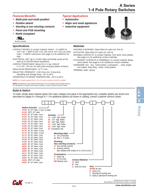
Models AvailableFeatures/Benefits• M ulti-pole and multi-pos ition • Positive detent• Shorting & non-shorting contacts • Panel and PCB mounting • RoHS CompliantTypical Applications •A utomotive • M ajor and small appliances • I ndus trial equipmentSpecificationsCONTACT RATING: Q contact material: Switch - 2.5 AMPS @125 V AC; 1 AMP @ 250 V AC; 350 mA @ 125 V DC (UL/CSA). Carry - 5 AMPS continuous. See page K-6 for additional rat-ings.ELECTRICAL LIFE: Up to 15,000 make-and-break cycles at fullload up to 300,000 detent operations.CONTACT RESISTANCE: Below 20 m Ω typ. initial @2-4 V DC, 100 mA, for both silver and gold plated contacts.INSULATION RESISTANCE: 10 9 Ω min.DIELECTRIC STRENGTH: 1,000 Vrms min. @ sea level.O perating and storage temp: -30º to 85ºC OPERATING & STORAGE TEMPERATURE: -30ºC to 85ºCNOTE: Any models supplied with Q, B or G contact material are RoHS compliant. NOTE: Specifications and materials listed above are for switches with standard options. For information on specific and custom switches, consult Customer Service Center.MaterialsHOUSING & BUSHING: Glass filled 6/6 nylon (UL 94V-0).ACTUATOR: Glass filled 6/6 nylon (UL 94V-0).MOVABLE CONTACTS: Q contact material: Coin silver, silver plated.See page K-6 for additional contact materials.STATIONARY CONTACTS & TERMINALS: Q contact material: Brass,silver plated. See page K-6 for additional contact materials.HARDWARE: Nut - zinc, nickel plated. Lockwasher — steel, brightzinc plated. Stop Ring - brass, nickel plated.TERMINAL SEAL: Epoxy.Build-A-SwitchTo order, simply select desired option from each category and place in the appropriate box. Available options are shown and described on pages K–4 through K–7. For additional options not shown in catalog, consult Customer Service Center.Switch FunctionA100 SP, 30° Index, 12 pos. no stops A102 SPDT, 30° IndexA103 SP, 30° Index, 3 pos. A104 SP, 30° Index, 4 pos. A105 SP, 30° Index, 5 pos. A106 SP, 30° Index, 6 pos. A107 SP, 30° Index, 7 pos. A108 SP, 30° Index, 8 pos.A109 SP, 30° Index, 9 pos. A110 SP, 30° Index, 10 pos. A112 SP, 30° Index, 12 pos. A114 SP, 90° Index, 2 pos.A115 SP, 45° Index, 3 pos. A124 SP, 90° Index, 4 pos.A125 SP, 45° Index, 8 pos.A203 DP, 30° Index, 3 pos.A204 DP, 30° Index, 4 pos.A205 DP, 30° Index, 5 pos.A206 DP, 30° Index, 6 pos.A214 DP, 90° Index, 2 pos.A303 3P, 30° Index, 3 pos.A304 3P, 30° Index, 4 pos.A402 4PDT, 30° IndexA403 4P, 30° Index, 3 posContact Material Q Silver B GoldG Gold over silverActuator 15 1.500” high, flatted 03 .375” high, flatted 05 .500” high, flatted 14 1.500” high, flatted 42 1.654” high, metric S1 Screwdriver Slot Shorting/ Non-shorting Contacts N Non-shorting contacts S S horting c ontac ts (Not available with models A114, A124 & A214)TerminationsZ Solder lugC PC Thru-hole MC Modular base Seal NONE No seal E Epoxy sealF Splashproof bushing sealK Epoxy & splashproof bushing sealMounting Style R 3/8-32 threaded M M10 x .75 metric RotaryR o t a r y3P MODELS SCHEMATIC4P MODELS SCHEMATICDP MODELS SCHEMATICSP MODELS SCHEMATIC3P MODELSTERMINAL NUMBERS4P MODELSSP MODELS (omit terminals B, C & D)DP MODELS (omit terminals B & D)T e rminal numbers molded on bottom of housing.NOTE: * These models with ‘C’ or ‘MC’ terminations have additional terminal no. 9 as switch support only. This terminal is not connected electrically inside switch.All models with all options when ordered with ‘G’ or ‘Q’ contact material, see page K-6.RotaryS SHORTING CONTACTS (make-before-break)N NON-SHORTING CONTACTS (break-before-make)S1 SCREWDRIVER SLOT42 1.654” METRIC15 1.500” HIGH14 1.500” HIGH05 .500” HIGH03 .375” HIGHNOTE: Actuators shown in position 1, fully CCW.R o t a r y* Note: See Technical Data section of this catalog for RoHS compliant and compatible definition and specifications.1 M OVABLE CONTACTS: Copper alloy, with gold plate over nickel plate. STATIONARY CONTACTS & TERMINALS: Brass, with gold plate over nickel plate.2 M OVABLE CONTACTS: Coin silver, silver plated.STATIONARY CONTACTS & TERMINALS: Brass, silver plated (standard with all termination options).3 M OVABLE CONTACTS: Coin silver, with gold plate over nickel plate over silver plate. STATIONARY CONTACTS & TERMINALS: Brass, with gold plate over nickel plate over silver plate.All models with all options when ordered with ‘G’ or ‘Q’ contact material.NOTE: ‘G’ contact material is equivalent to both ‘B’ and ‘Q” contact materials.NOTE: Any models supplied with Q, B or G contact material are RoHS compliant. Option CodeContact & TerminalMaterialTypical UsageRatingCycles QSilver 2PowerSWITCH – 2.5 AMPS @ 125 VAC; 1 AMP @ 250 VAC (UL/CSA)CARRY – 5 AMPS CONTINUOUS 6,000SWITCH – 350 mA @ 125 VDC (UL/CSA)CARRY – 5 AMPS CONTINUOUS 15,000BGold 1Low level/ Dry circuit0.4 VA MAX. @ 20 V AC OR DC MAX 15,000GGold over silver 3Low level/ Dry circuitor power0.4 VA MAX. @ 20 V AC OR DC MAX15,000SWITCH – 350 mA @ 125 VDC (UL/CSA)CARRY – 5 AMPS CONTINUOUS15,000SWITCH – 2.5 AMPS @ 125 VAC; 1 AMP @ 250 VAC (UL/CSA)CARRY – 5 AMPS CONTINUOUS6,000RotaryAVAILABLE HARDWARE(FIG. 1)(FIG. 2)(FIG. 3)REMOVABLE CLIPLOCATINGT ABSTANDOFFK EPOXY & SPLASHPROOF BUSHING SEALF SPLASHPROOF BUSHING SEALNONE NO SEALE EPOXY SEALStop ringPART NO.767B00201Material: BrassFinish: Nickel platedSetting Stops on A112 and A125 ModelsThe number of switch positions is adjustable on A112 and A125 models only by means of a stop ring provided with each switch. The number of positions is pre-set on all other models and the stop ring is factory installed.Soldering1. Insert switch base only into PC board.2. Do not bend terminals.3. W ave soldering recommended at 500F solder temperature.4. H and solder at 500F, 10 sec. max./terminal.Switch Assembly 1. H old housing/shaft assembly by housing. Remove protective cap by squeezing tabs and discard. (FIG. 1)2. D o not push on switch shaft. Detent mechanism will come apart.3. W hile holding switch housing, align locating tab on base with notch on housing and engage 4 housing latches in slots on base. (FIG. 2)4. Push firmly on housing until latches snap in place.5. R emove clip from shaft and discard. Assembly is complete. (FIG. 3)Cleaning 1. F lux clean using vapor degreaser and forced rinse or triple bath method.2. Do not allow switch base to ‘trap’ fluids.3. F reon TMC, TF or Methylene Chloride give excellent results.To set stops: Turn shaft fully counter-clockwise and insert stop ring tab in desired hole. Install lockwash-er and nut to retain stop ring for both PC and panel mounting. Switch without stop ring has 12 positions.Soldering, Cleaning and Assembly Instructions for ‘MC’ Termination Option。
台安变频器说明书
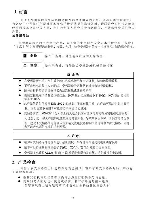
1.前言为了充分地发挥本变频器的功能及确保使用者的安全,请详阅本操作手册。
当您使用中发现任何疑难而本操作手册无法提供您解答时,请联系台安科技各地区经销商或本公司业务人员,我们的专业人员会乐于为您服务,并请您继续采用台安产品。
※使用须知变频器是精密的电力电子产品,为了您的生命财产安全,本手册中有「危险」「注意」等字样提醒您在搬运、安装、使用、检查变频器时的安全注意事项,请您配合遵守。
危险操作不当时,可能造成严重的人身伤害。
注意操作不当时,可能造成变频器或机械系统损坏。
危险z在变频器断电后,在主板上的红色充电指示灯未熄灭前,请勿触摸线路板z不可在送电过程中实施配线,变频器处于运行状态时请勿检查线路板。
z请勿自行拆装或更改变频器内部连接线或线路及零件z变频器接地端子请务必正确接地。
200V级:接地阻抗小于100Ω;400V级:接地阻抗小于10Ω。
z此产品的销售须根据EN61800-3的规定,于家庭使用时,此产品可能会引起电磁干扰,在此情况下使用者可能需要采取适当的量测。
z变频器安装于600KW(含)以上的大电力供应系统或电源侧有加装进相电容器时,可能会引起一极大峰值的电流流经电源输入端,导致其发生故障。
为预防此情况发生,建议于变频器的电源输入端加装交流电抗器抑制浪涌电流以保护变频器,同时也可改善电源供应端的功率因素。
注意z请勿对变频器内部的组件进行耐压测试,半导体零件易受高电压击穿损坏。
z绝不可以将变频器输出端子T1(U)、T2(V)、T3(W) 连接至交流电源。
z变频器主电路板CMOS集成电路易受静电影响及破坏,请勿触摸主电路板。
2. 产品检查每台台安变频器在出厂前均做过功能测试,客户拿到变频器拆封后,请执行下列检查步骤。
z变频器的机种型号是否正确符合您所订购的型号与容量。
z变频器是否因运送不慎造成损伤,若有损坏请勿接入电源。
当您发现有上述问题时请立即通知台安科技各区业务人员。
第一章安全注意事项B使用时注意事项送电前注意所选用的电源电压必须与变频器的铭牌规格相匹配。
欧诺克 直流伺服 驱动器 产品说明书

深圳市欧诺克科技有限公司Shenzhen ONKE Technology Co., Ltd.座机:*************27381841电话:邓先生135****7106陈先生139****0920邮箱:***************网 址 : 地址:广东省深圳市宝安区福海街道怀德翠湖工业园13栋稳定的质量是我们赖以生存的根本优质的服务是我们继续发展的前提客户的满意是我们唯一追求的目标产品画册Product gallery专业生产伺服驱动器、伺服电机及自动化控制系统深圳市欧诺克科技有限公司直流伺服驱动器目录匠心制造精益求精“一、公司介绍03二、直流伺服驱动器091.驱动器介绍与型号说明092.DC系列技术指标133.DE系列技术指标174.DE2系列技术指标215.BC系列技术指标256.驱动器应用领域297.驱动器外设配件31 0102C O M P A N Y PROFILE以精密制造引领未来Leading the future with precision manufacturing公司简介Company Profile深圳市欧诺克科技有限公司成立于2010年,是一家专业研发生产伺服电机和驱动器的高新技术企业,公司技术力量雄厚,检测手段先进,欧诺克人本着不求最全,只求最精的信念,为生产出各类伺服电机、各类驱动器而不懈奋斗。
欧诺克人以鹰的精神,挑战尖端,生产出性价比的各类伺服电机和驱动器,以鹰的敏锐洞察力洞察市场,随时改进、创新来满足市场的需求。
深圳市欧诺克科技有限公司产品主要有:伺服驱动器、伺服电机、直流伺服驱动器,直流伺服电机,交流伺服驱动器,交流伺服电机,低压伺服驱动器,低压伺服电机,直线电机驱动器,DDR马达驱动器,音圈电机驱动器,直流无刷驱动器,直流无刷电机,CANopen总线,EtherCAT总线,电子凸轮伺服系统,大功率伺服驱动器、大电流伺服驱动器,专用伺服驱动器和自动化控制系统,十年来凭借精湛的技术与国内国外众多知名企业公司建立了互利共赢的合作。
百灵达V-AMP说明书
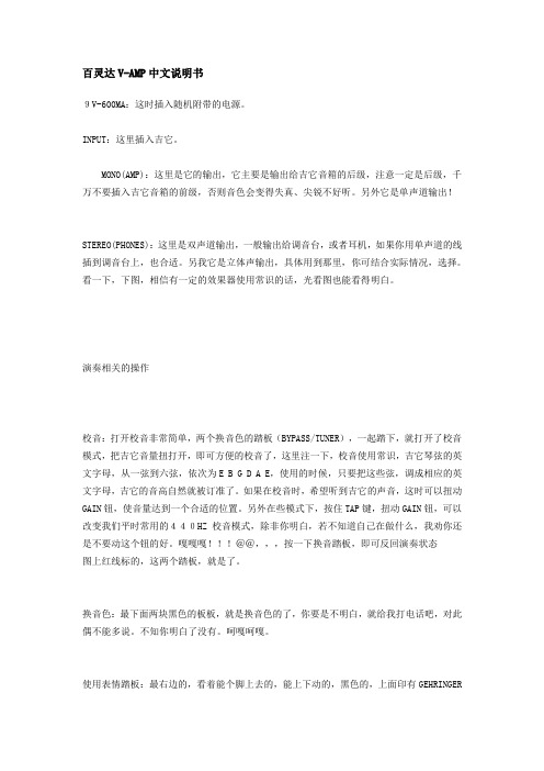
百灵达V-AMP中文说明书9V-600MA:这时插入随机附带的电源。
INPUT:这里插入吉它。
MONO(AMP):这里是它的输出,它主要是输出给吉它音箱的后级,注意一定是后级,千万不要插入吉它音箱的前级,否则音色会变得失真、尖锐不好听。
另外它是单声道输出!STEREO(PHONES):这里是双声道输出,一般输出给调音台,或者耳机,如果你用单声道的线插到调音台上,也合适。
另我它是立体声输出,具体用到那里,你可结合实际情况,选择。
看一下,下图,相信有一定的效果器使用常识的话,光看图也能看得明白。
演奏相关的操作校音:打开校音非常简单,两个换音色的踏板(BYPASS/TUNER),一起踏下,就打开了校音模式,把吉它音量扭打开,即可方便的校音了,这里注一下,校音使用常识,吉它琴弦的英文字母,从一弦到六弦,依次为E B G D A E,使用的时候,只要把这些弦,调成相应的英文字母,吉它的音高自然就被订准了。
如果在校音时,希望听到吉它的声音,这时可以扭动GAIN钮,使音量达到一个合适的位置。
另外在些模式下,按住TAP键,扭动GAIN钮,可以改变我们平时常用的440HZ校音模式,除非你明白,若不知道自己在做什么,我劝你还是不要动这个钮的好。
嘎嘎嘎!!!@@,,,按一下换音踏板,即可反回演奏状态图上红线标的,这两个踏板,就是了。
换音色:最下面两块黑色的板板,就是换音色的了,你要是不明白,就给我打电话吧,对此偶不能多说。
不知你明白了没有。
呵嘎呵嘎。
使用表情踏板:最右边的,看着能个脚上去的,能上下动的,黑色的,上面印有GEHRINGER的LOGO的,踏板,就是表情踏板了。
使用它的时候,要看一眼下图那个地方是什么模式。
这里有一个红颜色的灯,会表示目前在那一个模式上,WAH:代表哇音,VOLLME:代表音量EFFECT:代表打开或关闭效果SPEED:代表一个值。
比如晃动的快慢等。
这四种模式只有在WAH模式下,需要开启外,其它都不需要,往下往上踏,即会产生作用。
VanAmps 单通道回声效果器 'Sole-Mate' 产品说明书
Reverbamates e r i e s “Sole-Mate”by VanAmpsa Limited Liability CompanySingle Output Reverb EffectOwner’s ManualVanAmps, LLC thanks you for yourpurchase.Check us out on the web atPlease read the followingprecautions regarding theoperation of this unit.•Never attempt to use this device inwet locations.•Use only the supplied AC poweradaptor with this unit.•Refer all servicing to qualifiedpersonnel.•Make sure the amplifier is properlygrounded and/or polarity is correct.•Make sure the source instrument isproperly grounded.•Read and follow all operatinginstructions.Read on to get important and useful information to get the most out of your Reverbamate, “Sole-Mate”.Powering the Sole-MateThe Sole-Mate is powered by the included AC adaptor. The adaptor is a 12-volt AC/1000 ma power supply transformer, and is the only one that can be used with the Sole-Mate. Many pro musicians will order an extra at the time of purchase as a backup.•Using any other adaptor can and will destroy the unitand of course void the warranty.•* See notes below.It is best to plug the adaptor’s mini jack into the unit before plugging it into the AC outlet. This eliminates any arcing that could occur when plugging into the mini jack after AC voltage is applied to the adaptor. The Sole-Mate unlike its predecessor is designed to run on the supplied AC adaptor only. The green LED indicates there is power to the unit. If this does not come on, check the source where the adaptor is plugged in to see if there is power there.* A note to users of pedal power units, call VanAmps if you have any concerns or questions regarding the power requirements of the Sole-Mate. The Sole-Mate runs on 12 VAC, not DC, so make sure your unit supplies the correct power. There are several pedal power units on the market, specifically the Voodoo Lab’s Pedal Power AC is one of the recommended units, and it can supply the required 12 VAC.* Vintage amplifiers with two-prong AC plugs should be properly changed to grounded three-prong type. When using an amp with non-polarized two prong AC plugs, check for proper polarity by reversing the plug in the AC outlet for the position, which produces the least amount of hum and noise.Using the Sole-MateThe Reverbamate “Sole-Mate” has one output on the back panel and one input on the front panel. Connect the output of the Sole-Mate to your amplifier’s guitar input and connect your guitar to the input of the Sole-Mate. When using other effect pedals in conjunction with the Sole-Mate, connect them either before or after the Sole-Mate according to the instructions given for those devices.Hookup DiagramAMPLIFIERReverb In/Out switchThis switch cuts and engages the reverb effect when pressed alternately; it does not turn the power to the unit on/off. The red LED indicates when the reverb effect is engaged.AUX JackThe AUX jack and switch are there so that a user of atremolo/vibrato or other grounding type switching function on the amp can be utilized without the need for yet another pedal. The Fender® vintage amp users will find this most useful. Owners using the Sole-Mate’s AUX function on other makes of amps will need to find out if the function they want to switch is compatible with this type of switching. Some vintage amps have an RCA type jack for the tremolo switching, so use of a 1/4”female to RCA male audio adaptor is required when using a standard guitar cord.Sole-Mate ControlsDwell- This controls the amount of gain the dry signal has that feeds the reverb circuit, i. e. how hard the springs in the reverb pan are driven. When first becoming familiar with the Sole-Mate’s controls and how they affect the output, use small adjustments until the sound you are after is achieved. The Sole-Mate’s dwell control is very responsive so using large changes in the controls range will prevent the user to hear the important subtleties that this control can contribute to the overall sound. Output Levels - this controls the level of the signal derived from the reverb generating circuitry, which is then mixed with the dry signal from the guitar at the output of the Sole-Mate. Here again, the user is urged to make small adjustments so that the full potential of each control is understood. This control along with the dwell control, the musician will discover an endless array of reverb effects, from a background shimmer to a fully drenched surf effect, it’s there for you to discover.•The Reverbamate works with overdrive pedals too! Beaware that there can be much more gain going into theunit with an overdrive/boost pedal, start off at low safesettings on both controls.•Keep in mind that guitars all have varying signal levelsdepending on the type of pickups, no two guitars willproduce the same sound from the Sole-Mate given thesame control settings on the unit.•The input gain structure of the Sole-Mate was engineeredso that it could accept a wide variety of instruments, fulldwell settings could be too much for the Sole-Matereverb circuitry in some cases where a high level signalis feeding the unit. In these cases just turn the dwelldown, just as there will be some cases that the dwell willhave to be turned up quite a bit, to accommodate weakersignal levels. Your ears will tell you when to adjust theunit for optimal performance.General PrecautionsAlthough the Reverbamate is engineered to be stable within reason, it will “crash” when dropped, kicked, or thrown around. Please handle the unit as you would a fine microphone or other precision instrument. It is best to use the Sole-Mate on a stable surface, away from the amp it is used with to prevent possible acoustic feedback.The Sole-Mate is made for high impedance instrument sources, guitars, accordions, HI-Z microphones etc. Line level sources such as tape outputs and pre amp outs could potentially overdrive the inputs and cause damage. It is recommended that if attempting to use the Reverbamate in this manner, make sure there is a gain control on the source device so that the output signal can be controlled before the Sole-Mate’s input.Vintage amplifiers with two-prong AC plugs should be properly changed to grounded three-prong type. When using an amp with non-polarized two prong AC plugs, check for proper polarity by reversing the plug in the AC outlet for the position, which produces the least amount of hum and noise.Warranty InformationThe Sole-Mate is covered by a One(1) year limited warranty. VanAmps, LLC will repair or replace any unit deemed by us to have failed or proved to be defective under normal operating conditions. Warranty repairs will only be granted with pre authorization by VanAmps by calling (763) 529-1206 and obtaining a Return Authorization Number. The unit must be accompanied by a copy of the retailer’s sales receipt issued at the time of purchase. If no receipt is available, the actual date of manufacture will determine warranty status. Owner is responsible for returning the unit insured to VanAmps. VanAmps will provide return shipping.The Sole-Mate’s serial number can be located on the bottom of the unit and also stamped into the underside of the top along side the area of the reverb pan.。
- 1、下载文档前请自行甄别文档内容的完整性,平台不提供额外的编辑、内容补充、找答案等附加服务。
- 2、"仅部分预览"的文档,不可在线预览部分如存在完整性等问题,可反馈申请退款(可完整预览的文档不适用该条件!)。
- 3、如文档侵犯您的权益,请联系客服反馈,我们会尽快为您处理(人工客服工作时间:9:00-18:30)。
第三章:材料参数那么多参数,从哪里入手呢?从AMPS的原理为切入点,AMPS是基于对泊松方程,电子和空穴的连续性方程,复合/产生方程的求解来对要设计器件的结构和性能进行模拟的。
那么,求解方程需要哪些参数,我们就要设置哪些参数。
AMPS适用与对半导体(单晶,非晶,多晶),绝缘体,金属的模拟。
3.1:半导体材料的参数【载流子寿命图像】对S-R-H 或B-T-B过程进行模拟(3.1)(3.2)(1)在稳定状态时候,Rn一般等于Rp。
所以只能在满足n-n0=p-p0的时候,这个寿命能同时应用于两种载流子。
用这种方法计算,AMPS提供了一种通过计算△n/R和△p/R的自洽检验(Self-Consistancy-Check:SCC)的方法。
那么,如果你相信线性模型很好地适用于两种载流子,而且存在一个寿命值可以同时适用于两种载流子,那么你就可以通过看AMPS计算出来的SCC寿命是否相等(和你自己输入的值)来检查结果是否是自洽的。
如果你想要寿命的概念和R的线性化应用于电子,那么你就可以假设方程(3.1)是有效的。
在这种情况下,就不同对空穴进行任何的限制了。
在运行的最后,AMPS将计算SCC的值。
如果你刚开始就是正确的,那么SCC的值会和你输入的值相等。
这是空穴的的SCC是没有意义的。
同样,这个方法适用于空穴。
在不确定电子和空穴的线性模型对某些器件内区域是否很好地适用的时候,可以假设线性化的寿命适用于电子和空穴,在运行AMPS,然后检查输出的SCC值,如果相等的话,那么你就可以继续做以后的步骤了。
如果在某些区域,SCC中电子寿命<<空穴寿命,AMPS告诉我们:考虑把线性模型运用于电子会更有意义。
因为这个时候,导带的电子式控制(主导controlling)载流子,因此,你输入的寿命值被重置为电子的寿命。
假如过程出来的SCC 电子寿命>>空穴寿命,情况刚好相反。
(2)用方程(3.1)(3.2)对方程的描述不会涉及到S-R-H复合的细节。
比如,它没有考虑载流子通过缺陷能级时候的影响(不管是DOS或者是捕获面积(capture-cross-sections)这个充放电都被过重的看待了)。
因此,这种描述不会涉及有可能在器件工作时候由于净电荷的出现而导致的场分布效应。
(3)对于S-R-H,净复合通过缺陷密度Nt的束缚如下:(3.3)其中和是热速率-空穴/电子交叉捕获面积(thermal velocity-hole/electron capture cross section)和Nt的乘积的倒数。
nt和pt的数量和缺陷在禁带能级中的位置成指数关系。
对于B-T-B净复合:(3.4)其中R是和材料有关的常数,(to first order:在一阶条件下??)和载流子的数量无关。
【DOS图像】用DOS进行模拟,复合的机制,束缚和缺陷的电荷状态等的细节都可以很完全的描述。
用这个方法,需要输入禁带中缺陷的分布和各空间区域的变化。
还需要交叉捕获面积的信息来量化多种缺陷对于电子和空穴的吸引能力。
当处理具有很大的缺陷密度比如非晶硅材料和多晶材料的纹理边界区域的时候,需要用到DOS图像来描述。
.如果没有用DOS,我们就无法描述由于在缺陷状态下净电荷的出现导致电场分布的变化。
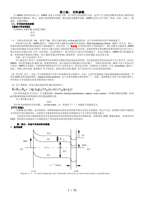
第一部分:单晶半导体材料的参数1.能带参数(3.5)(3.6)这些表达式在热平衡,即Efn=Epn=0时(相对于费米能级而言,一般Efn 为正,Efp为负),是有效的。
即使在有偏压的情况下,它们仍然适用。
从(3.5)和(3.6)中可以看出,我们必须给出材料层的能带有效状态密度Nv和Nc,电子亲和能Xe,禁带宽度Eg,x=L处的势垒高度,和半导体中靠近x=L 这个接触的电子亲和能。
2.定域(禁带中)参数实际上,在禁带中还存在着很多不同类型的能级,即使这种材料是单晶材料。
AMPS把这些能级归为两类:一类是缺陷(结构的和杂质)引起的,一类是由有意地掺杂引入的。
两类可能会有类施主态和类受主态。
一:掺杂能级的参数我们这里说的掺杂能级包括离散的能级和具有一定宽度(较高的能级边界和较低的能级边界之间)的带能级。
当重掺杂的时候,类似后者的禁带中的定域能带会出现。
这两种情况的任意结合,AMPS都是可以应付的。
●离散掺杂能级参数如上图所示,离散的是以单能级的形态出现的。
AMPS允许有九个施主能级和九个受主能级。
我们可以假设这些能级上的杂质已经全部电离,或者是用AMPS用费米-狄拉克分布计算这些状态的数量。
如果假设全部电离,第i个施主能级上的施主浓度N dDj或第j个受主能级上的受主浓度N dAj都必须被设置,于是这些能级上带电满足。
在这种情况下,AMPS计算全部电离的单位体积的施主状态和受主状态。
如果假设杂质没有全部电离,AMPS计算出它们的电离程度。
就是我们讨论的离散能级,可以用下列公式进行计算:(3.7)(3.8)(3.9)(3.10)在这些表达式中的n和p是作为半导体层的常数特性。
以上四个表达式在动态热平衡和有偏的状态下都是适用的。
在前者情况下,当动态热平衡的值用于n 和p时候,f Di和f Aj的表达式就可以忽略了,转变成叫合理的费米方程。
假设掺杂的离散能级全部电离,它们没有参与到复合;然而,如果没有全部电离,那么他们占有能级的概率有f Di和f Aj给出。
这些f Di和f Aj是由通过这些能级时候的S-R-H复合机制决定的。
因此,这些能级对复合有贡献。
(3.11)这些贡献是由上表达式等号右边的第一项和第三项来表述的。
从(3.7)---(3.10)中可以看出,基于不完全电离的假设,对于离散掺杂的模拟需要一些额外的信息。
在设置了各能级上受主和施主的浓度N dAi和N dDj后,我们也需要设置其能级距离导带和价带的距离(施主的为E DONi,受主的为E ACPj),还有各能级的交叉捕获面积。
●带掺杂能级参数前面已经提过,即使在单晶体材料中,在中掺杂的情况下也会导致带掺杂能级。
这些带能级的带电量有以下两个式子给出:(3.12)如果是类施主能级的话;(3.13)如果是类受主能级能级的话;第i施主带和第j受主带能级的(带电量)分别由一下两个式子给出:(3.14)(3.15)在这些表达式中,能级被电子占据的概率方程由以下式子给出:(3.16)(3.17)【其实(3.16)和(3.17)是对热平衡表达式的修正,使用与在有偏压的情况下,热平衡的式只有以下式子给出:(3.18)(3.19)】有以上各式可以看出,要模拟这样的情况,我们要设置很多的参数。
如第i层这样的掺杂带,需要能级参数E1i和E2i,浓度(N Di和N Aj),还有交叉捕获面积()。
二:缺陷能级的参数我们知道,即使在单晶材料中,也会出现有结构缺陷和杂志引起的定域能级。
这些能级会是类施主的,类受主的,离散的或是带形状的,就跟我们刚讨论的掺杂能级类似。
AMPS允许我们对一些据连续的方程形式(指数式,高斯式,常数式)的能级进行模拟。
●离散和带缺陷能级的参数通过这种形式的缺陷能级的数量和复合机制的机制同掺杂能级的计算没有区别,也就是说其数学表达式和要输入的参数是一样的。
然而,AMPS对这两种能级(掺杂能级和缺陷能级)的输入参数设置是不一样的。
●连续缺陷能级的参数所谓的连续缺陷能级是指在禁带中连续分布的定域能级,要注意区分它们跟在禁带中的特定能级和特定区域能级的不同。
AMPS对三种连续形式进行模拟:指数型,高斯型,常数型。
§指数型从价带延伸出来的类施主的Urbach带尾状态数在AMPS中是这样表示的:(3.20)其中E为正;同理,从导带延伸出来的类受主的Urbach带尾状态数可以这样表示:(3.21)其中E′为负;Ed和Ea是决定这些带尾斜率的特征能级。
这也是我们要自己设定的,当然还有Gdo和Gao(单位体积单位能级的状态数)。
由于这些能级会交换载流子,所以必须设置这些带尾中电子和空穴的交叉捕获面积。
§高斯型数学表达式为:(3.22)G Gd(施主)和G Ga(受主)是单位体积单位能级的状态数。
Epkd是施主高斯分布均值和导带底能级Ec的差,Epka式受主高斯分布均值和价带顶Ev的差值。
是分布的标准差。
对这种形式的缺陷进行模拟,不关需要以上的参数,还要有表征单位体积内全部的状态数的量,还有每种高斯分布的交叉捕获面积。
§常数型常数型的也类施主带和类受主带,主要式靠Eda来作为分界线的,所以要我们自己设置Eda。
在Eda和Ec之间的可以看做是类受主态,在Eda和Ev之间的可以看成是类施主态。
类受主态和类施主态的分别的单位体积单位能级状态数G MGA和E MGD没有必要相等。
这“转变能级”Eda是个正数,是以Ev为零点进行衡量的。
既然这里也是各缺陷能级,它们势必对载流子的输运产生影响,所以还要设置空穴和电子的交叉捕获面积。
AMPS中用来计算Urbach尾态,高斯型,和任意常数型分布的类施主态捕获的空穴数和类受主态捕获的电子数分别由以下两个式子给出:(3.23)(3.24)电子和空穴占据这些能级的概率方程由(3.16)(3.17)给出。
其中的n和p 由(3.5)和(3.6.)两式给出。
这些表达式同时适用于有偏的和热平衡的状态下。
AMPS计算通过指数型尾带,高斯型,和任意常数型缺陷分布时候的符合机制是用到式(3.11)中等号右边的第七项和第八项来实现的。
3:光特性参数这个比较简单,主要就是设置材料的光吸收系数和相对介电常数。
第二部分:非晶半导体材料参数在这里,我们假设非晶半导体的材料特征由图3.1中显示的那样,不管它是在器件中的哪一个位置。
而且我们还假设在单晶体中所讨论的定域态等等所有的态和光学参数在这里也全部都适用。
相对于半导体,主要的区别在于非晶体由很低的迁移率,而且在在禁带中还有很大的定域态数量。
所以,我们要注意的只是在输入参数的时候对于参数值大小的改变就行了。
还有一点由必要注意一下,也是蛮重要的,就是在非晶体中有迁移率隙E Gu和光学隙E Gop的区分。
在单晶材料中,E Gu=E Gop=Eg;然而,在非晶体中,由于定域的带型能级和带-带之间的光的跃迁有可能存在不同的临界值。
于是,在非晶体智能光,E Gu=Ec-Ev;但是E Gop就需要我们自己输入了。
值得一提的是,AMPS中衡量材料的禁带宽带都是利用E Gu的。
实际上,Egop也只是作为一个课本上的内容来讲,真正决定哪个波长产生光载流子的是吸收系数表。
只要在表中存在对哪个波长的吸收系数,AMPS就假设这个吸收会在带中产生光载流子。
因此,Egop和吸收系数表要一致,但是真正起作用的是吸收系数表,它控制这临界光载流子的产生。
第三部分:多晶半导体材料参数多晶半导体含有由无规则区域组成的晶界。
