Igor Pro中文操作手册 - 1
(仅供参考)Phoenixpro使用说明(中文)

PhoenixPro用户指南 V e r s i o n:1.00C r e a t e:2009-02-03目录序言 (1)第一部分软件简介 (2)第二部分界面说明 (3)第三部分操作说明 (5)3.1安装USB驱动 (5)3.2软件安装 (5)3.2.1 软件的完整性检查 (5)3.2.2 安装软件 (6)3.3量产准备工作 (8)3.3.1 使用HUB (8)3.3.2 不使用HUB (10)3.4软件启动 (10)3.4.1 打开量产软件 (10)3.4.2 配置软件 (10)3.4.3 启动软件 (11)3.5投入设备量产 (12)3.6软件关闭 (16)3.7软件升级 (17)第四部分注意事项 (19)4.1量产之前需注意的事项 (19)4.2量产过程中需注意的事项 (19)4.3出错处理 (20)第五部分USB驱动程序安装 (23)附A 常见问题及解决方案 (26)附B 快速操作指南 (27)序言1序言此手册是为PhoenixPro量产工具使用说明,它由软件简介、界面说明和操作指南等组成,全面介绍了量产工具的流程和使用方法。
本文档使用范围仅限于PhoenixPro量产工具使用用户。
文档结构:z软件简介z界面说明z操作说明z注意事项z驱动程序安装z FAQz快速指南2第一部分软件简介第一部分软件简介PhoenixPro量产工具通过样机与PC的连接的USB通道下载固件包到样机中。
整个量产工具由认证文件、固件包和量产软件组成,认证文件和固件包默认情况下存放在key文件夹中,PC端USB驱动程序默认存放在UsbDriver文件夹中。
为了提高生产效率,PhoenixPro量产工具支持无USB HUB和有USB HUB情况下多台样机升级,理论上最多可以支持127台样机同时升级,为了保证量产工具升级的正确性建议7台同时升级,建议不要超过8台,设备过多,量产速度会因为USB通道速度限制而下降。
7台同时升级且固件包大小为100M情况下,平均每个样机的升级时间约为10s。
普罗巴克指纹锁I系列使用说明书-中文
2
351
功能介绍
开门功能
本指纹锁支持指纹、密码、钥匙、组合开门四种标准开门方式,以及遥 控(选配)开门方式。
反锁功能
门内外上提把手都可实现反锁,亦可驱动天地杆;门内旋转小旋钮, 实现门内锁死功能,此时在门外无论采用哪种方式都不能开门。
普罗巴克指纹能门锁!在您使用本产品前,请务必仔细阅读使用说 明书,它将帮您更快更有效的了解和正确使用您所选购的指纹锁。为方便您日后的查 阅,也请您保存好本书。 本说明书主要向您介绍了普罗巴克 I100 指纹锁的基本结构和功能,并向您讲解 了安装和日常使用的方法。为了让您更便捷地了解和解决使用过程中可能出现的一些 问题,本说明书还向您列举了日常维护保养方法和常见问题解决方法等信息,方便您 的查阅。 本说明书是为我司出品的 I100 系列指纹锁量身定做的使用说明书,不一定能适 用于我司其他型号的智能门锁,更不适用于其他品牌的产品。我们尽可能给您提供 可靠信息,但我们也避免不了一些无法控制的疏漏,请您多加包涵! 本说明书仅作为使用参考,您所购买的产品的实际外观、具体配置和功能以您所购 买的产品型号实物为准。本系列产品可能会有部件或者整机的性能与可靠性的优化调 整,但不会实质性地影响到您对产品的使用,望您谅解!
前锁体
后锁体
1
174 78
81 39
173 78 33
80
388
386
正视图(单位:mm)
侧视图(单位:mm)
340
后视图(单位:mm) 侧视图(单位:mm)
产品特点
时尚风格:融合 Ipone 时尚现代设计理念,将经典黑色镜面的触摸屏幕与镀 铬金属边框完美结合,凸显时尚动感气息。
罗因华测电测机操作

机台各部位简介
华测电测机
PASS灯亮绿色 Fail 灯亮红色
电源开关
LED荧幕 找点探棒插座 模块测试点 操作按键
按鍵介紹~~~功能說明 1/3
Func Setup Print File Save Learn Stat
系统功能选单 系统设定选单 打印功能选单 档案管理设定 储存测试&数据文件设定 短断路学习 列示测试统计资料
测试项目不良的判断
电测主要问题
LED显示信息
分析原因
PASS
FALL OPEN SHORT
INSULATION
各个测试项目都要通过测试
产品不通过某项设定造成的结果 开路是指该产品某个功能节点断开
短路是指该产品某两个或多个功能节点并在 一起 绝缘是指功能点与点之间电阻达不到要求 导通是指线材电阻过大达不到设定参数要求 错位是指功能点的位置与标准的不一样
C
M.W
如何操作电测机
~~~罗因
罗英机台各部位简介
Fail LED(红色) Pass LED(绿色) LED屏幕
I/O PORT(模块测试点)
操作按键
找点探棒插座
按键介绍~~~功能说明 1/3
READ TEST
SINGLE STEP FUNC RESET
自我读取标准资料 执行测试 单边测试 循序测试 功能键 系统重新启动
3.2 测试电压设定(V) 按
.. V Hipot
进行电压设定
A. V/Ω SETUP 1 .Cond. Ω:1Ω 2 .Hipot V:500V 3 .Ins. Ω:50 ΜΩ
3.3 绝缘阻抗设定(ΜΩ) 按 进行绝缘设定
H.V. 进行高压时间设定 TIME B. HV/INS SETUP 1 .HV Time:0.1s 2 .Ins Fail No:3
Gel pro中文说明书

第一部分 软件介绍及本使用手册的一些定义欢迎使用Gel-Pro凝胶分析软件,这是一个功能强大,且非常容易学习操作的专业级科学软件,作为科学图像分析系统,该系统的先进与品质在全球数以万计的实验室得到了认可。
使用本软件,可以做以下一些工作:●可以精确的处理一些实验-DNA、RNA以及蛋白质电泳凝胶-Southern、Northern 和western Blots-Dot和 Slot Blots-微孔板-菌落计数-膜杂交●把实验结果发表●打印图像、分析结果以及注解●把图像或结果存储起来在使用本软件之前,有一些必要的计算机知识需要掌握:●会激活应用程序●会使用鼠标●会使用下拉式菜单●会选择及编辑文本●会保存和打印工作如果对Microsoft Windows的操作比较生疏,建议先熟练Microsoft windows的基本操作。
定义:●双击连续快速双击鼠标左键●单击单击鼠标左键●选中单击一个目标后,此目标反显●选择用鼠标单击一个目标后,按住鼠标左键不放,然后移动鼠标将全部目标覆盖●拖动用鼠标选择一个目标后,按住鼠标左键不放,然后移动鼠标到预定位置●组合键用手按住指定按键后,再单击鼠标左键●在本文中出现的此标记是下—步的意思第二部分 图像技术概述什么是图像处理?一幅图像就是一个物体或一组物体的视觉描述。
图像处理就是对一幅图像所含信息根据特定的用途进行处理。
数字图像处理是一种计算机操作的特殊的图像处理方式。
你可能比较熟悉照片图像,但是照片并不能用计算机进行分析,这是因为计算机是以数字方式而不是以图形方式工作的。
为了使用计算机处理一幅相片,图像必须转换成数字方式。
这个过程就是图像数字化。
图像数字化数字化过程把一幅图像划分成平行的格点或阵列,这些格点或阵列被称为图像元素或像素。
在计算机中图像就是以这些数字格点或位图描述的。
位图中的每一个像素由它在格点中的位置表示,如行(x)和列(Y)。
方便起见,通常把位图左上角位置点设为参考点(0,0)。
IGORPro6.2使用方法详细介绍-睿驰整理

IGORPro6.2使⽤⽅法详细介绍-睿驰整理1IGOR Pro - OverviewIGOR Pro is an interactive software environment for experimentation with scientific and engineering data and for the production of publication-quality graphs and page layouts. IGOR has been used by tens of thousands of technical professionals since its introduction in 1989. Here are a few highlights.IGOR Pro是为科学⼈员和数据⼯程师提供交互式软件实验环境,以及制作符合出版要求质量的图形和页⾯布局。
从1989年IGOR开发以来,已经有数万名专业科技⼈员使⽤。
IGOR Pro produces journal-quality scientific graphs and exports high-resolution graphics formats such as Encapsulated PostScript (EPS) and PDF.IGOR Pro可以⽣成符合学术期刊要求的⾼质量科学图像和⾼分辨率的图像格式,类似有EPS格式跟PDF格式。
IGOR Pro handles large data sets very quickly.IGOR Pro可以快速处理⼤数据集。
IGOR Pro includes a wide range of capabilities for scientific and engineering analysis and graphing.IGOR Pro可以为科研、⼯程分析和绘图需求提供⼤范围能处理能⼒。
普罗巴克指纹锁I系列使用说明书-中文

门内外上提把手都可实现反锁,亦可驱动天地杆;门内旋转小旋钮, 实现门内锁死功能,此时在门外无论采用哪种方式都不能开门。
常开功能
本锁可设置常开状态,在常开状态下可直接下压把手开门。 启用常开:指纹或密码(管理密码除外)验证成功后,在转动把手开门之前, 长按数字键“9”,提示操作成功,进入常开状态。常开状态下绿色指示灯闪 烁(约每 3 秒闪一次)。 取消常开:采用任意方式正确开门一次(机械钥匙除外)或取下电池断 电,取消常开。
操作与使用.....................................................................................2 出厂状态设置......................................................................................... 2 用户权限对比......................................................................................... 2 键盘功能说明......................................................................................... 2 进入管理菜单......................................................................................... 2 用户管理................................................................................................. 2 系统设置................................................................................................. 2 查看功能................................................................................................. 2 扩展功能................................................................................................. 2 采集指纹要领......................................................................................... 2 开门方法................................................................................................. 2 应急电源使用......................................................................................... 2 电池的安装和使用................................................................................. 2 常开功能设置......................................................................................... 2
GOPLCP 用户手册说明书
GOPLCPUSER'S MANUAL V 0.9OHO-Elektronikwww.oho-elektronik.de Author: M.RandelzhoferOHO-ElektronikMichael RandelzhoferRudolf-Diesel-Str. 885221 DachauGermanyWEB: www.oho-elektronik.deEMAIL: **********************Phone: +49 8131 339230FAX: +49 8131 339294©2005 OHO-Elektronik - Michael RandelzhoferAll rights reservedDisclaimer:Under no circumstances OHO-Elektronik - Michael Randelzhofer is liable for consequential costs, losses, damages, lost profits.Any schematics, pcb or program parts are under the copyright of OHO-Elektronik - Michael Randelzhofer, and can only be reproduced by permission of this company.The contents of this USER'S MANUAL are subject to change without notice.However the main changes are listed in the revision table at the end of this document. Products of OHO-Elektronik - Michael Randelzhofer are not designed for use in life support systems, where malfunction of these products could result in personal injury.The products of OHO-Elektronik - Michael Randelzhofer are intended for use in a laboratory test environment only. They can generate radio frequency energy (depending on the downloaded design and application), which can disturb local radio or TV equipment, and so they have not been tested to be CE compliant.If you encounter any technical problems or mistakes in this document, please contact*******************************, serious hints are very appreciated.Trademarks:All brand names or product names mentioned are trademarks or registered trademarks of their respective holders.PAL and GAL are registered trademarks of Lattice Semiconductor Corp.1. Table of contents:1. Table of contents: (3)2. GOPLCP - GOPxxx Low Cost Programmer (5)3. Schematics (6)4. Module Layout Top View (7)5. Literature (8)6. USER'S MANUAL Revisions (9)2. GOPLCP - GOPxxx Low Cost ProgrammerThe GOPLCP is a Xilinx download cable III [1] compatibe download cable for the GOPxxx family of OHO-Elektronik.Some modifications to the original schematics were made.The buffers of the download cable are feed back buffers to incorporate Schmitt Trigger functionality.Printer port pin 15 has a pulldown (R1).Without this pulldown, VCC sense is always sensed OK.This is a design mistake of the original Xilinx download cable.The GOPLCP JTAG port is connected via a 2mm cable to a 2mm IDC connector.The red color trace of the IDC cable denotes that on this side of the IDC connector is pin 1. This connector is compatible to [2] and [3] but pin 13.Pin 13 of the connector is a buffered CTRL signal of pin 5 of the printer port.This signal is low active, and enables the buffers.However the download software IMPACT never disables this signal.The GOPLCP cable is tested to operate in the voltage range of 2,8 to 5,5 V.GOPxxx devices always operate the cable at voltages between 3,3 and 5,5V.3. Schematics4. GOPLCP Layout Top View5. Literature[1] XILINX Parallel Download Cable/docsan/data/alliance/jtg/fig26.htm[2] DS097 Xilinx Parallel Cable IV/bvdocs/publications/ds097.pdf[3] DS300 Platform Cable USB/bvdocs/publications/ds300.pdf6. USER'S MANUAL RevisionsVersion Date Comments V0.9 23/10/2005 Prerelease。
IgorPro中文操作手册-1

IgorPro实用教程代码第1章

Igor Pro实用教程代码第1章1.1.7Variable v1,v2String s1=”hello”,s2Make/N=100 data1Print 2+sqrt(3)+5^3+6^0.3Print sin(1),ln(3),exp(2)Make/O/N=100 data1Setscale/I x,0,2*pi,data1Data1=sin(x)Fft data1Make/O/N=100 data1Data1=x+gnoise(1)Curvefit line data1/DDisplay data1Edit data1Display data1ModifyGraph mode(data1)=3,marker(data1)=19Sin(1) //errorPrint sin(1)1.2.1Make/O/N=100 dataSetscale/I x,0,1,dataData=xEdit data //只显示data内容Edit //显示data内容和x坐标信息Make/O/N=200 sinx;Setscale/I x,0,2*pi,sinx;sinx=sin(x);Display sinx;Make/O/N=200/C cmpwave;Make/O/T/N=200 twave;Setdatafolder root;//设定当前目录Newdatafolder tmp;//创建一个名为tmp的目录Make/O/N=200 root:tmp:cmpwave;setscale/P x,0,2*pi/199,”s”,sinxsetscale/I x,0,2*pi,”s”,sinxDuplicate/O oldwave,newwave;dupplicate/O/R=(x1,x2) oldwave,newwave;dupplicate/O/R=[p1,p2] oldwave,newwave;Make/O data={1,2,3}Make/O dataSetscale/P x,0,0.001,dataVariable tau=0.01Data=exp(-x/0.01)Make/O data1Data1=data[p]1.2.5Variable v1; //申明一个普通变量Variable/C v1; //申明一个复数变量Variable/G v1; //申明一个全局变量String str; //申明一个字符串变量1.2.6Function func()String curr=getdatafolder(1) //获取当前目录Setdatafloder mydestfd //mydestfd应该存在,存放了要处理的数据//some thing to be doneSetdatafolder curr //恢复当前目录End1.2.11Integrate1D(UserFunctionName, min_x, max_x [, options [, count ]])Integrate [/DIM = d /METH=m /P/T][typeFlags ] yWaveA [/X = xWaveA ][/D = destWaveA ] [, yWaveB [/X = xWaveB ][/D = destWaveB ][, ...]]第2章2.1.1make/N=100/O gaussfun,lorfunsetscale/I x,-1,1,gaussfun,lorfungaussfun=exp(-x*x/0.01)lorfun=1/((x*x)+0.04)make/N=10 XY_Y={4,6,8,4,6,7,9,1,4,3}make/N=10 XY_X={3,5,1,4,7,5,8,6,9,2}Display gaussfun// 绘制gaussfun曲线Display XY_Y vs XY_X as “mygraph”//绘制XY曲线并且设定graph标题为mygraphDisplay/L=newLeft/B=NewBottomgaussfun as "mygraph"//以新建自由坐标轴newLeft和NewBottom绘制gaussfun曲线。
原子力显微镜简易中文操作手册(doc)

来的激光打在了四象限板(ABCD)相对中心位置。如图:
A
B
C
D
SUM=A+B+C+D Deflection=(A+B)-(C+D) Sum:表示光斑打到光电传感器上的总强度大小。 所以当我们调整 SUM 值最大后,在调整 Deflection 时,SUM 有时会发生变化, 这时我们需要再调整下,以使两个值都达到相对完美状态。
※对光作业指的是将定位激光正确的对准到探针悬臂表面合适位置,确保力学信号反馈 的准确度。
3. 开启位于控制器上的激光光源及为样品提供照明用的氙灯光纤光源。 氙灯光源亮度可以根据实际需求自由设定,以可以准确观察样品以及探针为标准。在正 式进入原子力显微镜扫描过程中,可以将其关闭,以延长其灯泡使用寿命。
时仍能上升,顺时针回调白色大扭至 100 左右(为扫描器的头部的直接调整提供
空间),继续逆时针调扫描器头部前面的大旋钮,使 Z voltage=30 左右,再调远 程控制器,直至满足要求。
※此方法为软下针方式,可越过“虚假”水膜,保护探针,成像质量以及对探针 的磨损最小,是我们所推荐的。 10.点击 Sum&Deflection 对话框中的 Withdraw,关闭光纤光源,有隔音柜的情况,就合上 隔音罩。 11.开始扫描,选择 Main 框中的 do scan。
6. 对光作业
通过扫描器头部后面 CCD 反射镜上的两个旋钮,上下左右调整运动来寻找到探针,
使其出现在视频窗口,调节扫描器头部后反射镜附近的聚焦旋钮,对探针聚焦以使 探针清晰。 调整扫描器头部上的 LDx 及 LDy 旋钮,一边观察视频窗口,一边观察 SUM 值大
美国AsylumResearch原子力显微镜简单中文操作技巧使用说明

美国Asylum Research原子力显微镜MFP-3D-SA标准型原子力显微镜简易中文操作手册(第一版)杭州葛兰帕科技有限公司AC Mode in Air轻敲模式(大气)1.开启原子力显微镜控制器、电脑以及减震台。
检查各个系统是否正常启动。
2.进入WindowsXP系统,启动Igor pro软件,在Igor pro软件的下方,开启视频窗口,由原子力显微镜CCD提供光学观察窗口,为观察样品、选取下针位置以及“对光作业”提供条件。
※对光作业指的是将定位激光正确的对准到探针悬臂表面合适位置,确保力学信号反馈的准确度。
3.开启位于控制器上的激光光源及为样品提供照明用的氙灯光纤光源。
氙灯光源亮度可以根据实际需求自由设定,以可以准确观察样品以及探针为标准。
在正式进入原子力显微镜扫描过程中,可以将其关闭,以延长其灯泡使用寿命。
4.装针作业:●将探针夹持器cantilever holder按照呈三角形排布的定位小球位置卡入探针台cantilever holder stand上。
●然后用螺丝启子把cantilever holder上的螺丝松开3~4圈,不可过松,防止螺丝滑脱。
●打开探针盒,用镊子拾取探针,注意夹取探针时的角度,要保住垂直夹取,夹取探针的位置也要中间偏前段一点,为将探针尾部推入螺丝夹具口提供足够操作空间。
●探针插入夹具口后,根据实际情况,再精细调整位置,使其大致处于正中间位置。
最后用大拇指和中指夹住螺丝刀,进行旋紧。
使用两个手指的目的,就是确保力量不要太大,防止夹碎探针或者把螺丝螺纹破坏。
●拧紧的原则是感觉有阻力后再拧1/4圈,(要视具体情况定)再用镊子轻轻触碰探针侧面,看其是否因为没有夹紧而发生移动。
●装入朝上放置的扫描器头部圆形槽口,注意定位小球的位置。
5.样品台准备工作●拿起MFP-3D原子力显微镜扫描器头部。
露出原子力显微镜平板式扫描板上的样品台。
●将承载有样品的载玻片或者功能模块(功能模块具体安装另行说明)放入样品台大致正中位置。
Igor Pro中文操作手册 - 1

Waves —Igor 的关键概念
我们使用专业术语 “wave” 来描述一个包含有数字矩阵的 Igor 对象。 Wave 是“waveform”的简称。Wave 是 Igor 最重要的概念。
Igor 最初被用来设计处理波形数据。一个典型的波形数据包含成千上万个在均匀间隔时间内测试的数据点。这些 数据通常由数字示波器,科学仪器或数模转换设备采集。
Chapter
I-1
I- Igor Pro 介绍
I- Igor Pro 介绍 ............................................................................................................................................. 1 Igor Pro 介绍................................................................................................................................................. 1 Igor 对象 ....................................................................................................................................................... 2
波形数据的特征在于它是沿着时间轴或者其他变量的值均匀间隔的。Igor 波的一个重要属性被称为 “X scaling” 它指定你的数据的间隔。Igor 在内存中记录波形上每一个点的 Y 轴数值,但通过波的 X scaling 来计算数据的 X 轴的值 。
golo系列产品使用说明书030101

golo 系列产品使用说明书更新日期:2014-05-27版权所有!未征得深圳市轱辘软件开发有限公司(下称“轱辘公司”)的书面同意,任何公司或个人不得以任何形式(电子、机械、影印、录制或其它形式)对本说明书进行复制和备份。
本手册专为轱辘产品的使用而设计,对于将之用于指导其它设备操作而导致的各种后果,本公司不承担任何责任。
本手册及其包含的所有范例若有更改,恕不另行通知。
因使用者个人或第三方的意外事故,滥用、误用该设备,擅自更改、修理该设备,或未按轱辘公司的操作与保养要求而致使设备损坏、遗失所产生的费用及开支等,轱辘公司及其分支机构不承担任何责任。
对于使用其它选用配件或损耗品而非轱辘公司原装产品或轱辘公司认可之产品而导致该设备损坏或出现问题,轱辘公司不承担任何责任。
正式声明:本说明书所提及之其它产品名称,目的在于说明本设备如何使用,其注册商标所有权仍属原公司。
本设备供专业技术人员或维修人员使用。
注册商标轱辘公司已在中国及海外若干国家进行了商标注册,其标志为LAUNCH。
在轱辘公司之商标、服务标志、域名、图标和公司名称还未注册之国家,轱辘公司声明其对未注册商标、服务标志、域名、图标和公司名称仍享有其所有权。
本手册所提及之其它产品及公司名称的商标仍属于原注册公司所有。
在未得到拥有人的书面同意之前,任何人不得使用轱辘公司或所提及的其它公司之商标,服务标志,域名,图标,公司名称。
您可以访问轱辘网址:了解轱辘产品信息;或写信至:中国深圳市龙岗区坂雪岗工业区五和大道北元征工业园深圳市轱辘软件开发有限公司客户服务中心收,与轱辘公司进行联系,征得其手册使用权之书面同意。
使用前须知✧此说明书适用于golo系列产品的Android与iOS版本;✧说明书内所有插图仅用作参考,具体请以软件实际显示为准;✧本仪器为精密电子仪器,使用中切勿摔碰。
✧尽量轻拿轻放,避免撞击。
✧本设备适用于12V蓄电池电压,严禁使用其它电源电压。
注:车辆维修操作并不仅局限以下注意事项,如需了解更多关于车辆诊断方面的情况,可查阅相应的车辆手册等。
米勒焊机操作说明书
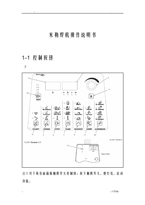
米勒焊机操作说明书1-1控制按钮注:1对于所有前面板触摸开关控制钮:按下触摸开关,使灯亮,启动功能。
2铭牌上的绿标表示TIG功能,灰色表示正常的手弧焊功能。
1 编码控制钮2 电流及参数显示表3 电压表4 极性控制钮5 工艺控制钮6 输出控制钮7 脉冲控制钮8 工序控制钮9 气体/电极力控制钮10 交流波型控制钮11 电流和点焊时间控制钮12 存储按钮13 电源开关1-2 编码控制钮1-3 电流控制钮1 A 电流控制按钮2 编码控制钮3 电流表注:当脉冲功能起作用时,按下电流控制按钮,转动编码器,以设定焊接电流或峰值电流。
1-4 电流及参数显示表1-5 电压表1-6 极性控制钮1-7 工艺控制钮1-8 高频启弧和高频TIG 启动程序提升启弧:当提升启弧按钮灯亮,按下列步骤启弧,在焊接开始处把钨极触及工件,用焊枪触发开关、脚控器或手控器接通输出和保护气。
把钨极在工件上保持1-2秒,然后慢慢提升。
焊极提起后,电弧生成。
在钨极触及工件前不存在正常的开路电压,仅在钨极和工件间存在较低的感应电压,直到钨极触及工件后才激发固态输出接触器,因此钨极不会出现过热、粘条或被污染。
应用:当不允许使用高频启弧或要取代划擦启弧时。
提升启弧用于DCEN或AC TIG 工艺。
高频启弧当高频启弧按钮灯亮,按下列步骤启弧,输出接通后,打开高频帮助启弧,启弧完成后关闭高频,断弧再次帮助重新启弧。
应用:当需要非接触启弧时,高频启弧用于DCEN GTAG工艺。
1-9 输出控制钮1 输出控制按钮按下按钮,直到希望参数的LED灯亮。
标准远控---应用:与脚踏或手控电流控制器一起使用远控触发。
注:脚控或手控远控电流控制器连接后,初始电流、起始坡升、终止坡降、及终止电流由远控器控制。
如果使用开/关型触发开关,它必须是一个维持开关,所有的程序功能有效,必须由操作者设定。
远控2T保持---应用:长距离焊接时,使用远控触发保持(2T)。
如果脚控或手控电流控制器连接到底电源上,仅触发输入有效。
iRig Pro I O 可移动音频 MIDI接口用户指南说明书

48V OFF
XLR
5
English
5. If you are using an instrument like a guitar or a bass, connect it using a regular 1⁄4” guitar cable to the iRig Pro I/O instrument input.
• Safety risk
• Apple device charging performances
• Noise performances
iRig Pro I/O
Thank you for purchasing iRig Pro I/O. Your package contains:
• iRig Pro I/O • 2 AA batteries (alkaline) • Mini-DIN to Lightning cable • Mini-DIN to USB cable • 2 MIDI cables • Velcro strap • Quick start guide • Registration card
2
English
Power adapter information
Use only the specified AC adaptor you can buy at: /irigpsu3a
Use only the specified AC adaptor (iRig PSU 3A) and make sure the line voltage at the installation matches the input voltage specified on the AC adaptor’s body.
GuitarPRO使用说明

Guitar-pro(简称GTP,这个软件的一开始格式就是.gtp而得名)是现时网络一个非常火爆的软件,几乎每个吉他网站所提供的吉他谱都有GTP格式。
而且界面很直观地把六线谱为主要输入形式,只要你熟悉纸张的吉他谱上手GTP来说更是得心应手。
对初学者来说,只要在GTP上简单地输入谱例它就会即时为你示范演奏,可以在练习中事半功倍,的确是难得的吉他MIDI制作软件。
Guitra-pro现在已经出了5.2版,向下的还有3.0版,2.16版,2.2版。
老琴友们可能还记得一个很出色的吉他网站——吉他扒手。
可以说,GTP在国内发扬光大在一定程度上和这个网站有很大的关系!相当年,我也是吉他扒手的粉丝,可惜后来关闭了。
现在我们就对GTP5.2版从安装到设置和简单打谱作简单的介绍!GTP5.2和一般软件的安装没什么分别,首先选择安装语言,我们就选U.S.English就行了!安装完后选择Chinese(GB),OK!重启计算机!GTP就可以正常动行了!GTP5.2在下边有提供下载(附注册码)。
GTP5.2第一次运行时会自动弹出MIDI设置窗口。
这里必须要进行简单的设置,否则可能会有不发声的问题!我们在Port Device一定选择你系统的声卡,Instrument Patch选择General MIDI 把后一项打钩,设置好后按一下中间那个喇叭,如果有发出一段琴声就证明设置完成了!如果没有音乐发出把选项交替设置试试,直至成功!在这里要提醒大家,GTP播放的音乐其实就是MIDI,效果的好坏与硬件中的声卡有直接关系,GTP5.2自带出色的软波表,提升播放MIDI音乐的效果!以下是gtp下载地址本站提供下载地址:Guitarpro5.2精简版下载(11.2M)视频教学以下就对GTP的操作进行简单介绍GTP本身也自带了很多示范歌谱的。
现在你就可以用GTP将它们打开,熟悉的六线谱就会出现在你的眼前。
当然了,GTP还可以为你演奏歌谱,如上图,按下从开头演奏键,GTP马上为你演奏一份歌谱就这么简单。
igo Rhino Products 1REV.01说明书

INSTALLATION INSTRUCTIONSPRODUCT SAFETY & LEGAL DISCLAIMER© 2016 Go Rhino Products. All rights reserved589 W. Apollo St., Brea, CA 92821 P: 888 427 4466•IMPORTANT READ ALL INSTRUCTIONS CAREFULLY BEFORE INSTALLING, FAILURE TO DO SO MAY CAUSE PERSONAL INJURY OR DAMAGE TO PRODUCT AND/OR PROPERTY.•Review the product package and contents prior to beginning the installation. Take care when opening the packaging and removing items. If a return is needed you will want to return the product in its original packaging if possible.•This instruction guide is provided as a GENERAL installation guide, some vehicles vary dimensionally and may require additional steps.•Test fit the product on the vehicle prior to any third party modifications and or finishing. Themanufacturer and/or distributors do not accept responsibility for third party charges, labor and or third part replacement modifications. Some modifications may void the factory warranty.•Exercise due-diligence when installing this product. The manufacturer and distributors of this product do not accept any responsibility for vehicle damage or personal injury resulting from the installation of this product. Careless installation and operation can result in serious injury or equipment damage.•This product is for general off-road use. All liability for installation and use rests with the owner/operator.•INSTALLER: Once installation is complete, please return this guide along with other documentation included in this product back to the consumer for future reference. The manufacturer/distributors of this product do not guarantee this particular version will be available at a later date.R E V 3 05/13/2016PART NO.●5994000T PRODUCT DESCRIPTION:●OVERLAND OVERHEAD RACKAPPLICATION: ●JEEP WRANGLER JK UNLIMITEDINSTALLATION INSTRUCTIONS INJURY HAZARDPlease complete a shop and tool inspection prior to beginning the installation.•Always make sure you have a clean, dry and well lit work area.•Always remove jewelry, loose fitting clothing and wear protective gloves and eye protection.•Always use extreme caution when jacking or raising a vehicle for work. Set the emergency brake and use tire/wheel blocks and jack stands. Refer to the vehicle manufacturer hand book. Utilize the vehicle manufacturers designated lifting points.•Always use appropriate and adequate care in lifting parts during disassembly and installation. Seek help in lifting heavy or large items into place. Utilize jacks and or lifting devices when available.•Always insure products are secure during disassembly and installation.•Always wear eye protection and take steps to protect any exposed skin during the installations. Drilling, cutting and grinding plastic and metal may create flying particles that can cause injury.•Always use extreme caution when drilling, cutting and or grinding on a vehicle. Thoroughly inspect the area to be drilled, on both sides of material, prior to modification and relocate any objects that may become damaged.•Always assemble and tighten all fasteners per the installation instructions.•Always route electrical cables carefully. Avoid moving parts, parts that may become hot and rough or sharp edges.•Always insulate and protect all exposed wiring and electrical connections.MAINTENANCE AND CARE•Always perform regular inspections and maintenance on mounts and related fasteners.•Periodically check and tighten all fasteners.•Stripped, fractured, or bent fasteners must be replaced.•After washing the vehicle make sure to fully dry all surfaces.•In areas with cold temperatures make sure to wash the product often to remove harmful materials used on road ways.•Never use abrasive cleaners or polish compounds. Clean with a gentle soap and water. If you use wax use a non-abrasive automotive wax such as pure carnauba wax.WARNINGSome products have been designed to work together with factory rear sensor systems, factory forward facing sensor systems and factory air bags.•Installation of some of these products may alter the factory sensor system performance.•Factory sensors may read shackles or hooks protruding from the fairlead and or tow hooks.•All sensor testing is completed by Go Rhino Products and or third party testing labs on modified vehicles.•Sensor sensitivity, factory sensor housing, orientation, and operating conditions are all variables that will influence functionality of the sensors.•Installation of some product may effect the factory air bag systems.•Some products allow the use of third party products such as winches, shackles, hooks, etc. Follow the respective manufacturers operating instructions for use with our products.•Make sure to fully understand the product, it’s intended use and operation prior to use.INSTALLATION INSTRUCTIONSIf you need installation service for your new product, call the authorized distributor from whom you purchased the product or an authorized installation service company which can be found by calling toll free 1-888-427-446621/2 HourTOOLS NEEDED FOR INSTALLATION:•1/2”, 9/16” Socket & Wrench, Ratchet & Ratchet Extension •Phillips Screw Driver•5/32” & 3/16” Hex Key •Drill Motor, 3/8” & ½” Drill BitESTIMATED TIME FOR INSTALLATION:PARTS INCLUDED IN THIS LIST:Go Rhino recommends you, the installer, read this installation instruction manual from front to back before installing the product. You may also click here to view an installation video or visit /Installation-Videos.ITEM QTY.DESCRIPTION ITEM QTY.DESCRIPTIONITEM QTY.DESCRIPTION115¼” x 3/4" Button Head Hex Drive Screw (SS)9165/16” x 1” Hex Head Bolt (SS)1783/8” Flat Washer (SS)21¼” 1 1/4" Button Head Hex Drive Screw (SS)10165/16” Lock Washer (SS)1823/8” x 1” Hex Head Bolt 341/4" X 1 1/2" Hex Head Bolt (SS)11185/16” Flat Washer (SS)1923/8” Lock Washer 412¼” Lock Washer (SS)1225/16” Nylon Lock Nut (SS)2043/8” Flat Washer 512¼” Flat Washer (SS)1323/8" X 1" Button Head Hex Drive Screw (SS)2123/8” Hex Nut68¼” Flat Washer (Plastic)1443/8” x 1 ½” Hex Head Bolt (SS)2223/8” Locking Pin with Squared Wire Retainer74Adhesive Backed Rubber Washer 1523/8” x 2 ¾” Shoulder Bolt 238Polyurethane Bushing 81Spacer, 1/2" OD, 7/16" Long 1663/8” Lock Washer (SS)244Bushing Sleeve(SS)Stainless SteelINSTALLATION INSTRUCTIONS PARTS INCLUDED IN THIS LIST:ITEM QTY.DESCRIPTION ITEM QTY.DESCRIPTION25 1 Front Bracket (Driver)318Cross Bar Gasket261Front Tube (Driver)321Rear Post (Driver) 274Plastic Cap331Front Bracket (Passenger) 282Roof Rail341Front Tube (Passenger) 298Cross Bar351Rear Post (Passenger) 304Thread PlateINSTALLATION INSTRUCTIONS PARTS INCLUDED IN THIS LIST:ITEM QTY.DESCRIPTION ITEM QTY.DESCRIPTION361Tail Light Cover (Driver)421Tail Light Cover (Passenger)371Rear Bracket (Driver)431Rear Bracket (Passenger)381Rear Bracket Gasket (Driver)441Rear Bracket Gasket (Passenger)391Lower Support Bracket-B(Driver)451Lower Support Bracket-A(Passenger) 401Lower Support Bracket-A(Driver)461Lower Support Bracket-B(Passenger) 411Upper Support Bracket (Driver)471Upper Support Bracket (Passenger)36373839404146 4243444547Reference the installation instruction included with the WLF Windshield Light frame, and complete the installation of the WLF Windshield Light frame.Driver RearStep-1Remove the (2) Phillip’s screws securing OEM taillight to the vehicle, disconnect taillight wiring from the vehicle wiring harness and remove the taillight from vehicle.Step-2Position the driver side rear bracket on the body panel area where the OEM taillight wasremoved. Align and level the rear bracket and use the (4) mounting holes in the bracket as a guide and mark the location of each hole on the body panel, (FIGURE 1).Step-3Set the driver side rear bracket aside and drill 3/8” holes through the body panel at the (4) marked locations. Note: The lower right body panel area has an interior panel, drill a 3/8” hole through both the outer and inner body panel.Step-4Re-drill only the lower right hole on the outer body panel to 1/2” as a spacer tube will be installed at this location.Step-5Apply the supplied gasket to the back of the driver side bracket, (FIGURE 2).Use the (4) mounting holes in the bracket as a guide and mark the location of each hole on the body panel. Drill 3/8” holes through the body panel at the (4) marked locations.Note:The lower right body panel area has an interior panel, drill a 3/8” hole through both the outer and interior body panel, then re-drill only the lower right hole on the outer body panel to 1/2”FIGURE 1FIGURE 2INSTALLATION INSTRUCTIONS373738Driver RearStep-6Attach the lower right hole in the driver side rear bracket to the body panel using (1) ¼” x 1 1/4” button head hex drive screw, (1) ¼” plastic flat washer, (1) spacer tube and lower support bracket-B, (FIGURE 3 & 4).Step-7Attach the two upper holes in the driver side rear bracket to the body panel using (2) ¼” x 3/4” button head hex drive screws, (2) ¼” plastic flat washers and the upper support bracket, (FIGURE 3 & 4)Step-8Attach the lower left hole in the driver side rear bracket to the body panel using (1) ¼” x 3/4” button head hex drive screw, (1) ¼” plastic flat washer and lower support bracket-A, (FIGURE 3 & 4).Step-9Attach the lower support brackets to the body structure using (1) 3/8” x 1” hex bolt, (2) 3/8” flat washers (1) 3/8” lock washer and (1) 3/8” hex nut, (FIGURE 4).View from inside1-62-6-84118-19 20-2139 40View from outsideFIGURE 3 FIGURE 4Passenger RearStep-10Remove the (2) Phillip’s screws securing OEM taillight to the vehicle, disconnect taillight wiring from the vehicle wiring harness and remove the taillight from vehicle.Step-11Position the passenger side rear bracket on the body panel area where the OEM taillight was removed. Align and level the rear bracket and use the (4) mounting holes in the bracket as a guide and mark the location of each hole on the body panel, (FIGURE 5).Step-12Set the passenger side rear bracket aside and drill 3/8” holes through the body panel at the (4) marked locations.Step-13Apply the supplied gasket to the back of the passenger side bracket, (FIGURE 6).Use the (4) mounting holes in the bracket as a guide and mark the location of each hole on the body panel. Drill 3/8” holes through the body panel at the (4) marked locations.FIGURE 5FIGURE 6INSTALLATION INSTRUCTIONS434344Passenger RearStep-14Attach the lower left hole inthe passenger side rear bracket tothe body panel using (1) ¼” x 3/4”button head hex drive screw, (1) ¼”plastic flat washer, and lowersupport bracket-C, (FIGURE 7 & 8).Step-15 Attach the two upper holesin the driver side rear bracket to thebody panel using (2) ¼” x 3/4”button head hex drive screws, (2) ¼”plastic flat washers and thepassenger side upper bracket,(FIGURE 7 & 8).Step-16Attach the lower right holein the driver side rear bracket to thebody panel using (1) ¼” x 3/4”button head hex drive screw, (1) ¼”plastic flat washer and lowersupport bracket-D, (FIGURE 7 & 8).Step-17Attach the support bracketsto the body structure using (1) 3/8”x 1” hex bolt, (2) 3/8” flat washers(1) 3/8” lock washer and (1) 3/8”hex nut, (FIGURE 8).View from inside18-19 20-214647View from outsideFIGURE 7FIGURE 81-64345INSTALLATION INSTRUCTIONSStep-18Align the holes and attach the passenger side front tube and (1) plastic cap to one of the rails using (1) ¼” x 1 1/2” hex bolt (1) 1/4” lock washer and (1) 1/4” flat washer, and (1) 3/8” x 1 1/2” hex bolt (1) 3/8” lock washer and (1) 3/8” flat washer, (FIGURE 19).Step-19Align the holes and attach the passenger side rear post and (1) plastic cap to opposite end of the rail using (1) ¼” x 1 1/2” hex bolt (1) 1/4” lock washer and (1) 1/4” flat washer, and (1) 3/8” x 1 1/2” hex bolt (1) 3/8” lock washer and (1) 3/8” flat washer, (FIGURE 10). Repeat the assembly for the driver side front tube, rear post and remaining rail.INSTALLATION INSTRUCTIONS3-4-514-16 17273428273-4-52835FIGURE 10FIGURE 914-16 17INSTALLATION INSTRUCTIONSStep-20Remove the paper backing, align and apply a rubber gasket to each end of the (4) cross bars, (FIGURE 11).Step-21 Position (1) thread-plate inside the rail of the passenger side front tube, rail and rear post assembly, and attach (1) cross bar to the rail using the thread plate, (2) 5/16” x 1” hex bolts (2) 5/16” lock washers and (2) 5/16” flat washers, (FIGURE 12).Step-22 Space the (3) remaining cross bars equally along the passenger side rail assembly and repeat step-21 to attach the cross bars to the rail, (FIGURE 13).Step-23With assistance attach the rail of the driver side front tube, rail and rear post assembly to the cross bars using the thread-plates, 5/16” x 1” hex bolts, 5/16” lock washers and 5/16” flat washers.FIGURE 11FIGURE 12FIGURE 13312930289-10 119-10 1129INSTALLATION INSTRUCTIONSStep-24Attach the passenger side front bracket to the top surface of the WLF light plate using (2) ¼” x ¾” button head hex drive screws, (2) ¼” lock washers and (2) ¼” flat washers, and to the inside surface of the WLF light frame using (1) 3/8” x 1” button head hex drive screw, (1) 3/8” lock washer and (1) 3/8” flat washer, (FIGURE 14). Leave the screws loose for final adjustment. Repeat for the driver side front bracket.13-16171-4 533WLF light plate WLF light frameFIGURE 14Step-25Assemble (2) bushings and (1) sleeve in the stub tube of each front tube and each end post, (FIGURE-15).INSTALLATION INSTRUCTIONS23 35243423FIGURE 15Stub TubeStep-26With assistance position the cargo rack assemble over the top of the vehicle then position the bushings in each rear support between the two tabs on each rear bracket. Align the bushing sleeve with the hole in the tabs and secure the rear supports to the rear bracket tabs using (1) 3/8” shoulder bolt, (1) 3/8” flat washer, (1) 5/16” flat washer and (1) 5/16” nylon lock nut, (FIGURE-16). Leave the shoulder bolts and nuts loose for final adjustment.INSTALLATION INSTRUCTIONSFIGURE 16Step-27 Position the bushings in each front tube between the two tabs on each front bracket. Align the bushing sleeve with the hole in the tabs and secure the front tubes to the front bracket tabs using a 3/8” locking pin with squared wire retainer, (FIGURE-17).Step-28Tighten all fasteners securing the cargo rack assembly, and components to the vehicle.FIGURE 1715-1711-122232372625INSTALLATION INSTRUCTIONSStep-29Re-connect the wiring to thevehicle wiring harness and re-install theOEM taillights using the Phillips screwsremoved in step-1Step-30Remove the paper backing, alignand apply a rubber washer around eachthreaded hole on the driver side rearbracket, (FIGURE 18). Repeat for thepassenger side.Step-31Align and attach the driver side tail light cover to the light bracket using (2) ¼” x ¾” button head hex drive screws, ¼” lock washers and ¼” flat washers, (FIGURE 19). Tighten the screws. Repeat for the passenger side.FIGURE 19FIGURE 18 71-453736INSTALLATION INSTRUCTIONS Remember to periodically check and retighten all OEM and supplied hardware.Go Rhino warrants to Buyer that for a period of five (5) years from the date of shipment of the product(s) (“Warranty Period”) for black finishes and chrome finishes, that such products will materially conform to the specifications set forth in Go Rhino’s specifications in effect as of the date of shipment(s) and will be free from material defects in material workmanship.Go Rhino warrants to Buyer that for the life of the product(s) from the date of shipment of the product(s) (“Warranty Period”) for polished stainless steel finished products purchased after April 2004, that such products will materially conform to the specifications set forth in Go Rhino’s specifications in effect as of the date of shipments and will be free from material defects in materi al workmanship. Warranty claims must be accompanied with the original invoice and photos of the product. It is the customer’s responsibility to clean regularly and protect finish with regular applications of a nonabrasive polish that is compatible with the product’s finish.This warranty covers the cost of the product only and does not include the cost of removal, installation, third party modifications or shipping of the product. In no event shall Go Rhino be liable to buyer or any third party for any damage or harm caused by the product or use thereof, regardless of weather such damages were foreseeable and whether or not Go Rhino has been advised of the possibility of such damages, not withstanding the failure of any agreed or other remedy of its essential purpose. This warranty is void if the product shows signs of alteration, misuse, mishandling, improper care, neglect, improper application and/or damage due to improper installation. With respect to any such product(s) during the limited warranty period, Go Rhino shall, in its sole discretion, either: (i) provide a one-time repair or replacement of such products (or the defective part) or (ii) credit or refund the price of such products at the pro rata contract rate provided that, if Go Rhino so requests, Buyer shall, at Go Rhino’s expense, return such product(s) to Go R hino. The remedies shall be the Buyer’s sole and exclusive remedy and Go Rhino’s entire liability for any breach of the limited warrant (ies).Go Rhino disclaims all other warranties except to the extent that any such warranty cannot be validly disclaimed under applicable law.Finish Limited Warranty:Limited lifetime on stainless steel products (after April 2004)5 year warranty on black powder coat products5 year warranty on chrome productsThis warranty does not cover exposed weldsFinish warranty covers peeling, flaking, or cracking. Washing all finishes regularly with car wash soap and rinsing well with water is the best method for maintaining the finish on your products. You must also protect the finish with nonabrasive automotive wax on a regular basis. The use of any compound which contains abrasives becomes a self-defeating exercise as the compound scratches the finish and opens it to corrosion. The use of harsh chemicals used to remove bugs and tar may also cause the finish to fail and should be avoided.If you are unsatisfied with your purchase please contact the establishment you purchased the product from.If you need to place a warranty claim or need assistance, the Go Rhino customer service team will answer any questions you may have. Please contact the Go Rhino customer service team at 1-888-427-4466 during normal business hours Monday thru Friday 7 am to 5 pm PST. You may also email ********************. In order to better serve you please provide a copy of the original invoice / receipt, a photo of the issue you are experiencing and a photo of the vehicle the product is installed on. All warranty returns must have an approved RGA number. The RGA number must be clearly marked on the exterior of the return package. All approved warranty returns must be shipped to Go Rhino Products, 1002 Carriers Drive, Laredo, Texas 78045.INSTALLATION INSTRUCTIONSLIMITED WARRANTYPRODUCT REGISTRATIONPlease remember to register your new purchase. You may register your product at . Registering your product may help speed any future warranty or customer service inquiries. Thank you again for purchasing from Go Rhino Products Please take a few minutes to view additional products for your vehicle and more at These installation instructions are available on the Go Rhino web site along with installation videos formany of our products. 。
igorpro说明
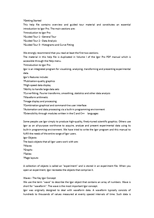
?Getting StartedThis help file contains overview and guided tour material and constitutes an essential introduction to Igor Pro. The main sections are:?Introduction to Igor Pro?Guided Tour 1 - General Tour?Guided Tour 2 - Data Analysis?Guided Tour 3 - Histograms and Curve FittingWe strongly recommend that you read at least the first two sections.The material in this help file is duplicated in Volume I of the Igor Pro PDF manual which is accessible through the Help menu.?Introduction to Igor ProIgor is an integrated program for visualizing, analyzing, transforming and presenting experimental data.Igor's features include:?Publication-quality graphics?High-speed data display?Ability to handle large data sets?Curve-fitting, Fourier transforms, smoothing, statistics and other data analysis?Waveform arithmetic?Image display and processing?Combination graphical and command-line user interface?Automation and data processing via a built-in programming environment?Extensibility through modules written in the C and C++ languagesSome people use Igor simply to produce high-quality, finely-tuned scientific graphics. Others use Igor as an all-purpose workhorse to acquire, analyze and present experimental data using its built-in programming environment. We have tried to write the Igor program and this manual to fulfill the needs of the entire range of Igor users.Igor ObjectsThe basic objects that all Igor users work with are:?Waves?Graphs?Tables?Page layoutsA collection of objects is called an "experiment" and is stored in an experiment file. When you open an experiment, Igor recreates the objects that comprise it.Waves - The Key Igor ConceptWe use the term "wave" to describe the Igor object that contains an array of numbers. Wave is short for "waveform". The wave is the most important Igor concept.Igor was originally designed to deal with waveform data. A waveform typically consists of hundreds to thousands of values measured at evenly spaced intervals of time. Such data isusually acquired from a digital oscilloscope, scientific instrument or analog-to-digital converter card.The distinguishing trait of a waveform is the uniform spacing of its values along an axis of time or other quantity. An Igor wave has an important property called "X scaling" that you set to specify the spacing of your data. Igor stores the Y component for each point of a wave in memory but it computes the X component based on the wave's X scaling.In the following illustration, the wave consists of five data points numbered 0 through 4. The user has set the wave's X scaling such that its X values start at 0 and increment by 0.001 seconds per point. The graph displays the wave's stored data values versus its computed X values.Waves can have from one to four dimensions and can contain either numeric or text data.Igor is also capable of dealing with data that does not fit the waveform metaphor. We call this XY data. Igor can treat two waves as an XY pair. In an XY pair, one wave supplies an X component and another wave supplies a Y component for each point in the pair.A few analysis operations, such as Fourier transforms, inherently work only on waveform data. They take a wave's X scaling into account.Other operations work equally well on waveform or XY data. Igor can graph either type of data and its powerful curve fitting works on either type.Most users create waves by loading data from a file. You can also create waves by typing in a table, evaluating a mathematical expression, acquiring from a data acquisition device, and accessing a database.How Objects RelateThis illustration shows the relationships among Igor's basic objects. Waves are displayed in graphs and tables. Graphs and tables are displayed in page layouts. Although you can display a wave in a graph or table, a wave does not need to be displayed to exist.Each object has a name so that it can be referenced in an Igor command. You can explicitly set an object's name or accept a default name created by Igor.Graphs are used to visualize waves and to generate high-quality printouts for presentation. The traces in a graph are representations of waves. If you modify a wave, Igor automatically updates graphs. Igor labels the axes of a graph intelligently. Tick marks never run into one another and are always "nice" values no matter how you zoom in or pan around.In addition to traces representing waveform or XY data, a graph can display an image or a contour plot generated from 2D data.Tables are used to enter, inspect or modify wave data. A table in Igor is not the same as a spreadsheet in other graphing programs. A column in a table is a representation of the contents of a wave. The wave continues to exist even if you remove it from the table or close the table entirely.Page layouts permit you to arrange multiple graphs and tables as well as pictures and annotations for presentation. If you modify a graph or table, either directly or indirectly by changing the contents of a wave, Igor automatically updates its representation in a layout.Both graphs and layouts include drawing tools for adding lines, arrows, boxes, polygons and pictures to your presentations.More ObjectsHere are some additional objects that you may encounter:?Numeric and string variables?Data folders?Notebooks?Control panels?3D plots?ProceduresA numeric variable stores a single number and a string variable stores a text string. Numeric and string variables are used for storing bits of data for Igor procedures (described below).A data folder can contain waves, numeric variables, string variables and other data folders. Data folders provide a way to keep a set of related data, such as all of the waves from a particular run of an experiment, together and separate from like-named data from other sets.A notebook is like a text-editor or word-processor document. You can use a notebook to keep a log of results or to produce a report. Notebooks are also handy for viewing Igor technical notes or other text documentation.A control panel is a window containing buttons, checkboxes and other controls and readouts. A control panel is created by an Igor user to provide a user interface for a set of procedures.A 3D plot displays three-dimensional data as a surface, a scatter plot, or a path in space.A procedure is a programmed routine that performs a task by calling Igor's built-in operations and functions and other procedures. Procedures range from very simple to very complex and powerful. You can run procedures written by WaveMetrics or by other Igor users. If you are a programmer or want to learn programming, you can learn to write your own Igor procedures to automate your work.Igor's ToolboxIgor's toolbox includes a wide range of built-in routines. You can extend it with user-defined procedures written in Igor itself and separately-compiled Igor extensions (plug-ins) that you obtain from WaveMetrics, from a colleague, from a third-party, or write yourself.Built-In RoutinesEach of Igor's built-in routines is categorized as a function or as an operation.A built-in function is an Igor routine, such as sin, exp or ln, that directly returns a result. A built-in operation is a routine, such as Display, FFT or Integrate, that acts on an object and may create new objects but does not directly return a result.The best way to get a sense of the scope of Igor's built-in routines is to open the reference volume of the PDF manual (choose Help->Manual) and scan the sections "Built-in Operations by Category" and "Built-in Functions by Category".For getting reference information on a particular routine it is usually most convenient to choose Help->Command Help and use the Igor Help Browser.User-Defined ProceduresA user-defined procedure is a routine written in Igor's built-in programming language by entering text in a procedure window. It can call upon built-in or external operations and functions as well as other user-defined procedures to manipulate Igor objects. Sets of procedures are stored in procedure files.Igor ExtensionsAn "extension" is a "plug-in" - a piece of external C or C++ code that adds functionality to Igor. We use the terms "external operation" or "XOP" and "external function" or "XFUNC" for operations and functions added by extensions. An extension can add menus, dialogs and windows to Igor as well as operations and functions.To create an extension, you must be a programmer and you need the optional Igor XOP Toolkit. See Creating Igor Extensions.Although creating an extension is a job for a C or C++ programmer, anyone can use an extension. The Igor installer automatically installs commonly used extensions in "Igor Pro Folder/Igor Extensions". These extensions are available for immediate use. An example is the Excel file loader accessible through Data->Load Waves.Less commonly used extensions are installed in "Igor Pro Folder/More Extensions". Available extensions are described under External Operations Index. To activate an extension, see Activating Extensions.Igor's User InterfaceIgor uses a combination of the familiar graphical user interface and a command line interface. This approach gives Igor both ease-of-use and programmability.The job of the user interface is to allow you to apply Igor's operations and functions to objects that you create. You can do this in three ways:?Via menus and dialogs?By typing Igor commands directly into the command line?By writing Igor proceduresThe Command WindowThe command window is Igor's control center. It appears at the bottom of the screen.At the bottom of the command window is the command line. Above the red divider is the history area where executed commands are stored for review. Igor also uses the history area to report results of analyses like curve-fitting or waveform statistics.Menus, Dialogs and CommandsMenus and dialogs provide easy access to the most commonly-used Igor operations.When you choose a menu item associated with an Igor operation, Igor presents a dialog. As you use the dialog, Igor generates a command and displays it in the command box near the bottom of the dialog. When you click the Do It button, Igor transfers the command to the command line where it is executed.As you get to know Igor, you will find that some commands are easier to invoke from a dialog andothers are easier to enter directly in the command line.There are some menus and dialogs that bypass the command line. Examples are the Save Experiment and Open Experiment items in the File menu.Using Igor for Heavy-Duty JobsIf you generate a lot of raw data you may find it worthwhile to learn how to put Igor to heavy-duty use. It is possible to automate some or all of the steps involved in loading, processing and presenting your data. To do this, you must learn how to write Igor procedures.Igor includes a built-in programming environment that lets you manipulate waves, graphs, tables and all other Igor objects. You can invoke built-in operations and functions from your own procedures to build higher-level operations customized for your work.Learning to write Igor procedures is easier than learning a lower-level language such as FORTRAN or C. The Igor programming environment is interactive so you can write and test small routines and then put them together piece-by-piece. You can deal with very high level objects such as waves and graphs but you also have fine control over your data. Nonetheless, it is still programming. To master it requires an effort on your part.The Igor programming environment is described under Programming Overview.You can also learn about Igor programming by examining the WaveMetrics Procedures and example experiments that were installed on your hard disk.Igor DocumentationIgor includes an extensive online help system and a comprehensive PDF manual.The online help provides guided tours, context-sensitive tips, general usage information for all aspects of Igor, and reference information for Igor operations, functions and keywords.The PDF manual contains mostly the same information except for the context-sensitive tips.The PDF manual, being in book format, is better organized for linear reading while the online help is usually preferred for reference information.Igor Tips (Macintosh only)Igor Tips present brief explanations of menus, dialogs and other user interface items. You turn Igor Tips on and off using the Help menu. When on, tips appear as you move your mouse over icons, menu items and dialog items.Status Line Help, Tool Tips and Context-Sensitive Help (Windows only)Igor's Windows help system provides three ways to get immediate help for an icon, a menu item, or a dialog item.Status line help automatically shows brief descriptions of menu items and icons in the status line area at the bottom of the main Igor Pro window.Tool tips provide very brief descriptions of icons when you point the cursor at the item. Context-sensitive help displays a pop-up window containing information about the menu item, icon or dialog item of interest. Context-sensitive help is accessed as follows:Menus and Icons: Press Shift+F1 to get the question-mark cursor and click the item of interest. Dialogs: Click the question-mark button in the upper-right corner of dialog to get the question-mark cursor , then click a dialog item.The Igor Help SystemThe Help menu provides access to Igor's help system, primarily through the Igor Help Browser.?Use the Help menu or press Help (Macintosh) or F1 (Windows) to display the Igor Help Browser. ?Use the Igor Help Browser Help Topics tab to browse help topics.?Use the Igor Help Browser Shortcuts tab to get a list of handy shortcuts and techniques.?Use the Igor Help Browser Command Help tab to get reference information on Igor operations and functions. You can also right-click operation and function names in Igor windows to access the reference help.?Use the Igor Help Browser Search tab to search Igor help, procedure and example files.Most of the information displayed by the help browser comes from help files that are automatically loaded at launch time. The Windows->Help Windows submenu provides direct access to these help files.The Igor ManualThe Igor PDF manual resides in "Igor Pro Folder/Manual". You can access it by choosing Help->Manual.The manual consists of five volumes and an index.Volume I contains the Getting Started material, including the Guided Tour of Igor Pro.Volumes II and III contain general background and usage information for all aspects of Igor other than programming.Volume IV contains information for people learning to do Igor programming.Volume V contains reference information for Igor operations, functions and keywords.Hard copy of the manual can be purchased from </wavemetrics>.Learning IgorTo harness the power of Igor, you need to understand its fundamental concepts. Some of these concepts are familiar to you. However, Igor also incorporates a few concepts that will be new to you and may seem strange at first. The most important of these are waves and experiments.In addition to this introduction, the primary resources for learning Igor are:?The Guided Tour of Igor ProThe guided tour shows you how to perform basic Igor tasks step-by-step and reinforces your understanding of basic Igor concepts along the way. It provides an essential orientation to Igor and is highly-recommended for all Igor users.?The Igor Pro PDF manual and online help filesYou can access the PDF manual through Igor's Help menu or by opening it directly from the Manual folder of the Igor Pro Folder where Igor is installed.You can access the help files through the Igor Help Browser (choose Help->Igor Help Browser) or directly through the Windows->Help submenu.?The "Examples" experimentsThe example experiments illustrate a wide range of Igor features. They are stored in the Examples folder in the Igor Pro Folder. You can access them using the File->Example Experiments submenu or directly from the Examples folder of the Igor Pro Folder where Igor is installed.You will best learn Igor through a combination of doing the guided tour, reading select parts of the manual (see suggestions following the guided tour), and working with your own data.Getting Hands-On ExperienceThis introduction has presented an overview of Igor, its main constituent parts, and its basic concepts. The next step is to get some hands-on experience and reinforce what you have learned by doing the Guided Tour of Igor Pro.?Guided Tour of Igor ProIn this tour we take a look at the main functions of Igor by stepping through some typical operations. Our goal is to orient you so that you can comfortably explore the program on your own. You will benefit most from this tour if you actually do the instructed operations on your computer as you read this tour. Screen shots are provided to keep you synchronized with the tour.TerminologyIf you have read Introduction to Igor Pro, you already know these terms:Experiment: The entire collection of data, graphs and other windows, program text and whatnot that make up the current Igor environment or workspace.Wave: Short for waveform, this is basically a named column of data with optional extra information.Name: Because Igor contains a built-in programming and data transformation language, each object must have a unique name.Command: This is a line of text that instructs Igor to do some task. Igor is command-driven so that it can be easily programmed.About the TourThis tour consists of three sections: "Guided Tour 1 - General Tour", "Guided Tour 2 - Data Analysis" and "Guided Tour 3 - Histograms and Curve Fitting".The General Tour is a rambling exploration intended to introduce you to the way things work in Igor and give you a general orientation. This tour takes 2 to 4 hours but does not have to be performed in one sitting.The second and third tours guide you through Igor's data analysis facilities including simple curve fitting.When you've completed the first tour you may want to explore freely on your own before starting the second tour.Note: You can execute the example commands in this help file by selecting the line or lines and pressing Control-Enter (Macintosh) or Ctrl+Enter (Windows).?Guided Tour 1 - General TourIn this exercise, we will generate data in three ways (typing, loading, and synthesizing) and we will generate graph, table, and page layout windows. We will jazz up a graph and a page layout with a little drawing and some text annotation. At the end we will explore some of the more advanced features of Igor Pro.Launching Igor ProThe Igor Pro application is typically installed in:/Applications/Igor Pro Folder (Macintosh)C:\Program Files\WaveMetrics\Igor Pro Folder (Windows)1. Double-click the Igor Pro application file on your hard disk.On Windows you can also start Igor using the Start menu.If Igor was already running, choose the File->New Experiment menu item.2. Use the Misc menu to turn preferences off.Turning preferences off ensures that the tour works the same for everyone.Entering Data1. If a table window is showing, click on it to bring it to the front.When Igor starts up, it creates a new blank table unless this feature is turned off in the Miscellaneous Settings dialog. If the table is not showing, perform the following two steps:1a. Choose the Windows->New Table menu item.The New Table dialog appears.1b. Click the Do It button.A new blank table is created.2. Type "0.1" and then press Return or Enter on your keyboard.This creates a wave named 搘ave0?with 0.1 for the first point. Entering a value in the first row (point 0) of the first blank column automatically creates a new wave.3. Type the following numbers, pressing Return or Enter after each one:1.21.92.64.55.15.87.88.39.7Your table should look like this:4. Click in the first cell of the first blank column5. Enter the following numbers in the same way:-0.12-0.081.310.540.470.440.20.240.136. Choose Data->Rename.7 Click "wave0" in the list and then click the arrow icon.8. Replace "wave0" with "time".Notice that you can't use the name "time" because it is the name of a built-in string function. We apologize for usurping such a common name.9. Change the name to "timeval".10. Select "wave1" from the list, click the arrow icon, and type "yval".11. Click Do It.Notice the column headers in the table have changed to reflect the name changes.Making a Graph1. Choose the Windows->New Graph menu item.The New Graph dialog will appear. This dialog comes in a simple form that most people will use and a more complex form that allows you to create complex multiaxis graphs in one step.2. If you see a button labeled Fewer Choices, click it.The button is initially labeled More Choices because the simpler form of the dialog is the default.3. From the Y Wave(s) list, pick "yval".4. From the X Wave list, pick "timeval".5. Click Do It.A simple graph is created.Touching up a Graph1. Position the cursor directly over the trace in the graph and double-click.The Modify Trace Appearance dialog appears. You could also have selected the corresponding menu item from the Graph menu.Note: The Graph menu appears only when a graph is the target window. The target window is the window that menus and dialogs act on by default.2. Choose Markers from the Mode pop-up menu.3. Select the open circle from the pop-up menu of markers.4. Set the marker color to blue.5. Click Do It.Your graph should now look like this:6. Position the cursor over the bottom axis line.The cursor changes to this shape: . This indicates the cursor is over the axis and also that you can offset the axis (and the corresponding plot area edge) to a new position.7. Double click directly on the axis.The Modify Axis dialog appears. If another dialog appears, click cancel and try again, making sure the cursor is showing.Note the Live Update checkbox in the top/right corner of the Modify Axis dialog. When it is checked, changes that you make in the dialog are immediately reflected in the graph. When it is unchecked, the changes appear only when you click Do It. The Modify Axis dialog is the only one with a Live Update checkbox.8. If it is not already showing, click the Axis tab.9. Choose On from the Mirror Axis pop-up.10. Click the Auto/Man Ticks tab.11. Click the Minor Ticks checkbox so it is checked.12. Click the Ticks and Grids tab.13. Choose Inside from the Location pop-up.14. Choose the left axis from the Axis pop-up menu in the top-left corner of the dialog and then repeat steps 8 through 13.15. Click Do It.Your graph should now look like this:16. Again double click the bottom axis.The Modify Axis dialog appears again.17. Click the Axis tab.18. Uncheck the Standoff box.19. Choose the left axis from the Axis pop-up menu and repeat step 18.20. Click Do It.Notice that some of the markers now overlap the axes. The axis standoff setting pushes out the axis so that markers and traces do not overlap the axis. You can use Igor's preferences to ensure this and other settings default to your liking, as explained below.21. Double-click one of the tick mark labels (e.g., "6") on the bottom axis.The Modify Axis dialog reappears, this time with the Axis Range tab showing. If another dialog or tab appears, cancel and try again, making sure to double click one of the tick mark labels on the bottom axis.22. Choose "Round to nice values" from the pop-up menu that initially reads "Use data limits".23. Choose the left axis from the Axis pop-up menu and repeat step 22.24. Click Do It.Notice that the limits of the axes now fall on "nice" values.Adding A Legend1. Choose the Graph->Add Annotation menu item.The Add Annotation dialog appears.2. Click the Text tab if it is not already selected.3. Choose Legend from the pop-up menu in the upper-left hand corner.Igor inserts text to create a legend in the Annotation text entry area. The Preview area shows what the annotation will look like. Note that the text "\s(yval)" generates the symbol for the yval wave. This is an "escape sequence," which creates special effects such as this.4. In the Annotation area, change the second instance of "yval" to "Magnitude".5. Click the Frame tab and choose Box from the Annotation Frame pop-up menu.6. Choose Shadow from the Border pop-up menu.7. Click the Position tab and choose Right Top from the Anchor pop-up menu.Specifying an Anchor point helps Igor keep the annotation in the best location as you make the graph bigger or smaller.8. Click Do It.Adding A Tag1. Choose the Graph->Add Annotation menu item.2. Choose Tag from the pop-up menu in the upper-left hand corner.3. In the Annotation area, type "When time is ".4. Choose Attach point X value from the Dynamic pop-up menu in the Insert area of the dialog. Igor inserts the "\0X" escape code into the Annotation text entry area.5. Type ", Magnitude is ".6. Choose Attach point Y value from the Dynamic pop-up menu.7. Switch to the Frame tab and choose None from the Annotation Frame pop-up menu.8. Switch to the Tag Arrow tab and choose Arrow from the Connect Tag to Wave With pop-up menu.9. Click the Position tab and choose "Middle center" from the Anchor pop-up menu.The dialog should now look like this:10. Click Do It.Your graph should now look like this:The tag is attached to the first point. An arrow is drawn from the center of the tag to the data point but you can't see it because it is hidden by the tag itself.11. Position the cursor over the text of the tag.The cursor changes to a hand. This indicates you can reposition the tag relative to the data point it is attached to.12. Click and drag the tag up and to the right about 1 cm.You can now see the arrow.13. With the cursor over the text of the tag, press Option (Macintosh) or Alt (Windows).The cursor changes to this shape: . (You may need to nudge the cursor slightly to make it change.)14. With the key still down, click and drag the box cursor to a different data point.The tag jumps to the new data point and the text is updated to show the new X and Y values. Option-drag (Macintosh) or Alt-drag (Windows) the tag to different data points to see their X and Y values..Notice that the tip of the arrow touches the marker. This doesn't look good, so let's change it: 15. Double-click on the tag.The Modify Annotation dialog appears.16. Click the Tag Arrow tab and change the Line/Arrow Standoff from "Auto" to "10".17. Click the Change button.The tip of the arrow now stops 10 points from the marker.Using PreferencesIf you have already set preferences to your liking and do not want to disturb them, you can skip this section.1. Use the Misc menu to turn preferences on.2. Click the graph window if it is not already active.。
- 1、下载文档前请自行甄别文档内容的完整性,平台不提供额外的编辑、内容补充、找答案等附加服务。
- 2、"仅部分预览"的文档,不可在线预览部分如存在完整性等问题,可反馈申请退款(可完整预览的文档不适用该条件!)。
- 3、如文档侵犯您的权益,请联系客服反馈,我们会尽快为您处理(人工客服工作时间:9:00-18:30)。
Igor 对象
所有 Igor 用户的基本工作对象为:
• Waves • Graphs • tables • Page layouts
对象的集合被称为 “experiment” 并存储于一个 experiment 文件中。 当你打开一个 experiment 文件,Igor 将重新 生成其中包含的对象。
波形数据的特征在于它是沿着时间轴或者其他变量的值均匀间隔的。Igor 波的一个重要属性被称为 “X scaling” 它指定你的数据的间隔。Igor 在内存中记录波形上每一个点的 Y 轴数值,但通过波的 X scaling 来计算数据的 X 轴的值 。
根据下图所示,波包含了从 0 到 4 的 5 个数据点。 用户已设置了 X scaling,即 X 的值从 0 开始每隔 0.001 秒取一 个点。 图像展示了该波形的数据值的存储是是随着 X 值计算的。
Igor Pro 介绍
Igor Pro 是一个对实验数据可视化,分析,转换和呈现的集成软件. Igor Pro 的特点包括: • 出版质量的图片 • 快速的数据展示 • 大数据集的处理能力 • 曲线拟合,傅立叶变换,平滑,统计和其他数据分析 • 波形算法
Chapter I-1 — Introduction to Igor Pro
Waves —Igor 的关键概念........................................................................................................................ 2 对象之间的关联....................................................................................................................................... 3 更多对象 .................................................................................................................................................. 3 Igor 工具箱 ................................................................................................................................................... 4 内建程序 .................................................................................................................................................. 4 用户自定义程序....................................................................................................................................... 4 Igor 扩展 ................................................................................................................................................... 5 Igor 的用户界面 ........................................................................................................................................... 5 命令窗口 .................................................................................................................................................. 5 菜单,对话框和命令行........................................................................................................................... 5 使用 Igor 进行深重度工作 .......................................................................................................................... 6 Igor 文档 ....................................................................................................................................................... 6 Igor 提示 (针对 Macintosh 电脑)............................................................................................................. 7 状态行帮助,工具提示,和上下文链接帮助 (针对 Windows 电脑) .................................................. 7 Igor 帮助系统 ........................................................................................................................................... 7 Igor 手册 ................................................................................................................................................... 7 Igor 学习 ....................................................................................................................................................... 8 经验分享 ...................................................................................................................................................... 8
波可以有 1 到 4 个维度,每个维度可以包含数字或文本信息。
I-2பைடு நூலகம்
Chapter I-1 — Introduction to Igor Pro
Igor 也能够处理不符合波形规范的数据。我们称它为 XY 数据。Igor 能把两个波处理为一个 XY 对。在一个 XY 对中,一个波支持对中每个数据点的 X 的数据值,而另一个波支持对中每个数据点的 Y 的数据值。
IGOR Pro
Version 6.36
WaveMetrics,Inc.
卷I
入门
目录
I- Igor Pro 介绍 ............................................................................................................................................. 1 I- Igor Pro 概览 ............................................................................................................................................. 9
Waves —Igor 的关键概念
我们使用专业术语 “wave” 来描述一个包含有数字矩阵的 Igor 对象。 Wave 是“waveform”的简称。Wave 是 Igor 最重要的概念。
Igor 最初被用来设计处理波形数据。一个典型的波形数据包含成千上万个在均匀间隔时间内测试的数据点。这些 数据通常由数字示波器,科学仪器或数模转换设备采集。
• 图片的展示与处理 • 结合了图形界面与命令行界面 • 集成于编程环境中的自动化与数据处理 • 使用 C 和 C++语言写入扩展模块 人们使用 Igor 简单的制作出高质量的,精确的科学图形。另有人们使用 Igor 作为分析的通用工具,并利用其内 置的编程环境。我们试着在整本手册中写下 Igor 使用者整体范围 的使用需求。
Igor computes a wave’s X values.
Point number
0
X value 0
Igor stores a wave’s data values in memory.
Data value
3.74
5.5
1
.001
4.59
5.0
2