机柜空调说明书
机柜使用说明书
机柜使用说明书1.概述本机柜为19英寸标准计算机机柜,主要用于网络、监控、计算机等领域,具有所有机柜的一般通用性尺寸规格:2000mm(不含轮脚)X 1100mm(深度)X 600mm(宽度)内部有效高度:42U颜色:黑色砂纹。
2.使用环境条件(1).工作电压:AC 220V~380V(2).工作温度:-5℃~+40℃(3).存储温度:-25℃~+55℃(4).相对湿度:5%~80%(5).机柜有效放置空间距离:≥2M(6).机房散热条件:内装空调(7).机房内部防雷、防静电装置:机房需内装接地及防雷电设施(8).消防报警及灭火系统:机房需安装因出现电路起火的报警装置及灭火设备机房内所有使用环境需要配备相应的检测设备:如温度计,湿度计等,若机柜存放于没有机房的环境工作,则需要房间具有空气流通条件形成对流,必要时可以在机柜内部配装风机散热。
3.系统的主要功能和主要指标(1).机柜的主要功能是将所有设备集成在机柜内部,便于安装调试、维护和管理,使机柜成了设备运行的载体,从而达到高效、安全的工作效果。
(2).LCD显示屏,便于集成显示用户需要的技术参数。
(3).相关指标:安全防护等级:IP45ESD:机柜内部前后门均接地脚轮载重:≥600KG机柜静态载重:≥1000KGGB/T 19520.1-2007 GB/T 19520.1-2007 电子设备机械结构 482.6 mm(19 in)系列机械结构尺寸第1部分:面板和机架GB/T 19520.2-2007 电子设备机械结构 482.6 mm(19 in)系列机械结构尺寸第2部分:机柜和机架结构的格距《公差标准》(GB1804-2000/GBT1184-1996)《喷涂质量标准》(GB/T5237.5-2000)4.产品特点及说明(1).机柜前门采用铝型材和弧形造型设计,使机柜整体具有较新颖和线条美感,前后门均为通风网孔,增加美感同时满足设计运行的散热要求,其外形有如下特点。
机柜使用说明书

机柜使用说明书1.概述本机柜为19英寸标准计算机机柜,主要用于网络、监控、计算机等领域,具有所有机柜的一般通用性尺寸规格:2000mm(不含轮脚)X 1100mm(深度)X 600mm(宽度)内部有效高度:42U颜色:黑色砂纹。
2.使用环境条件(1).工作电压:AC 220V~380V(2).工作温度:-5℃~+40℃(3).存储温度:-25℃~+55℃(4).相对湿度:5%~80%(5).机柜有效放置空间距离:≥2M(6).机房散热条件:内装空调(7).机房内部防雷、防静电装置:机房需内装接地及防雷电设施(8).消防报警及灭火系统:机房需安装因出现电路起火的报警装置及灭火设备机房内所有使用环境需要配备相应的检测设备:如温度计,湿度计等,若机柜存放于没有机房的环境工作,则需要房间具有空气流通条件形成对流,必要时可以在机柜内部配装风机散热。
3.系统的主要功能和主要指标(1).机柜的主要功能是将所有设备集成在机柜内部,便于安装调试、维护和管理,使机柜成了设备运行的载体,从而达到高效、安全的工作效果。
(2).LCD显示屏,便于集成显示用户需要的技术参数。
(3).相关指标:安全防护等级:IP45ESD:机柜内部前后门均接地脚轮载重:≥600KG机柜静态载重:≥1000KGGB/T 19520.1-2007 GB/T 19520.1-2007 电子设备机械结构 482.6 mm(19 in)系列机械结构尺寸第1部分:面板和机架GB/T 19520.2-2007 电子设备机械结构 482.6 mm(19 in)系列机械结构尺寸第2部分:机柜和机架结构的格距《公差标准》(GB1804-2000/GBT1184-1996)《喷涂质量标准》(GB/T5237.5-2000)4.产品特点及说明(1).机柜前门采用铝型材和弧形造型设计,使机柜整体具有较新颖和线条美感,前后门均为通风网孔,增加美感同时满足设计运行的散热要求,其外形有如下特点。
机柜空调使用说明书(RA-900W电子版)
图三
冷气机
电 控 箱
冷气机
图四
电控箱
错误
正确
-2-
错误
正确
泠逸工业制冷·安装使用说明书
机柜空调
2、安装方法 (1)当机组在搬运、装卸时,请始终保持设备处于垂直直立状态,不要将设备长期放在露天场所; (2)为使空调器的冷却效果最佳,请将机组直接安装在电气柜的外壁上或顶上(根据用户所选机型来决定), 请勿采用风管的形式进行送风,如若确实需要采用风管送风,请先咨询本公司技术工程师; (3)空调器在安装之前,请先确认好安装位置的强度是否能承载机组,以免造成人员受伤及设备损坏,当 安装在电气柜门上时,最好该扇箱门能固定不动,当需要打开时请先确认好加在门上的重量不会使整个电 气柜倾倒; (4)电气柜上必须开孔,以便使冷风能进入电控箱内,具体的开口尺寸请参见图五; (5)箱体开孔时请严格参照开口尺寸进行,孔口处的毛刺必须清除,以免划伤机组; (6)当长期使用时请注意安装螺栓是否损坏或脱落,若有而未加处理,将有可能导致机器掉落而损坏; (7)侧装式机柜空调的安装方式见下页图; (8)RA-900W 机柜空调安装开孔图见附页图纸;
-6-
泠逸工业制冷·安装使用说明书
机柜空调
菜单设置选项 回差设定 压缩机延时 温度设置下限 温度设置上限 模式选择 温度校正
DTS 8000ES 外挂式机柜空调操作及使用说明书
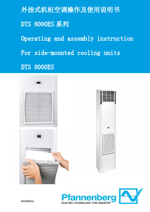
外挂式机柜空调操作及使用说明书1 手册提示 (5)2 搬运 (5)2.1 运输 (5)2.2 储运 (5)2.3 开箱 (5)3 供货范围 (6)4 一般信息 (6)5 铭牌 (6)6 安全 (7)7 功能 (7)7.1 配置与功能 (7)7.2 工作原理 (7)7.3 冷凝物 (8)8 技术规格书 (8)8.1电气原理图 (8)8.2备品备件 (9)8.3安装开孔 (9)8.4气流原理 (12)8.5技术参数 (12)9 安装 (16)9.1 概述 (16)9.2 安装工作 (16)9.3 电气连接 (17)10 运行条件 (17)11 投入使用和功能 (17)11.1 概述 (18)11.2 操作显示器 (18)11.3启动测试模式 (18)11.4 门触点 (18)11.5 设备故障 (19)12 参数查看与设置 (19)13 清洁和维护 (20)13.1 清洁 (20)13.2 维护 (20)14 停止使用 (21)15 故障排除 (21)16 保障条款 (21)附表I (22)1 Hints on the manual (23)2 Handling (23)2.1 Transport (23)2.2 Storage (23)2.3 Unpacking (24)3 Scope of delivery and options (24)4 General Information (24)5 Name plate (24)6 Safety (25)7 Function (25)7.1 Function and configuration (25)7.2 Operating principles (26)7.3 Condensate (26)8 Technical data (27)8.1 Circuit Diagram (27)8.2 Spare parts (28)8.3 Installation Cut-out (28)8.4 Airflow principle (31)8.5 Technical Data (31)9 Installations (35)9.1 General (35)9.3 Electrical connection (36)10 Operating condition (37)11 Putting into operation and function (37)11.1 General remarks (37)11.2 Operation display (37)11.3 Start-up / Test mode (38)11.4 Door contact (38)11.5 Equipment fault (38)12 Parameters View and Settings (39)13 Cleaning and Maintenance (40)13.1 Cleaning (40)13.2 Maintenance (40)14 When not in used (40)15 Trouble shooting (41)16 Warranty Conditions (41)Appendix I (42)1 手册提示此手册为百能堡电气科技有限公司(以下简称百能堡)提供的门装或侧装螺栓固定,外挂式机柜空调系列的安装运行指南。
山特精密空调一体机架空调用户手册说明书

客服热线:400-830-3938/800-830-3938Rack Type Air Conditioner User Manual 一体机架空调用户手册产品防伪为了切实保障您的用电安全,帮助您购买到真正的山特精密空调,请注意以下事项:1. 认准山特注册商标:、、、、。
2. 山特所有产品机身上均贴有“产品序列号”(产品序列号是唯一的,一个产品对应一个序列号);如果您购买到有疑问的山特产品,可通过以下途径向本公司反馈1.客服热线:400-830-3938/800-830-39382.品牌保护邮箱:*************************版权声明山特公司致力于技术创新,不断提供更好的产品和服务满足客户需求,对产品设计、技术规格的更新,恕不另行通知。
产品以实物为准。
请到山特网站w 下载最新版的产品说明书。
版权所有© 2020山特电子(深圳)有限公司1.1F OREWORD (1)1.2A IR CONDITIONER DESCRIPTION (1)1.2.1Principles of function (1)1.2.2Operating Conditions (1)1.3S TANDARDS (2)2.SAFETY NOTICES (2)3.INSTALLATION AND OPERATION (2)3.1M ECHANICAL INSTALLATION (2)3.2E LECTRICAL INSTALLATION (3)3.3P OWER-ON STEPS (4)4.SYSTEM FUNCTION INTRODUCTION4 4.1C OOLING (4)4.2H EATING (O PTION) (5)4.3D OOR ALARM (5)4.4C OMPONENT CONTROL MODE (5)4.5U NIT SEQUENCING CONTROL (OPTION) (5)4.5.1T IME S WITCHING (5)4.5.2T EMPERATURE SWITCH (5)4.5.3B OTH WORKING WITH HIGH TEMPERATURE (5)4.5.4D ISTURBANCE SWITCHING (5)4.6S ELF TESTING (6)4.7H YDROGEN DISCHARGING/EMERGENCY FAN (OPTION) (6)4.8A LARM (6)4.9U NIT MENU STRUCTURE (7)4.9.1Operation interface (7)4.9.2Menu structure (7)5.MAINTENANCE (8)5.1D AILY MAINTENANCE (8)5.2C OMPRESSOR MAINTENANCE (8)5.3C OMMON FAULT (9)1.简介 (15)1.1前言 (15)1.2空调器描述 (15)1.2.1工作原理 (15)1.2.2运行条件 (15)1.3符合标准 (16)2.安全注意事项 (16)3.安装和操作 (17)3.1空调器机械安装 (17)3.2电气安装 (17)3.3开机步骤 (18)4.系统功能介绍 (18)4.1制冷功能 (19)4.2制热功能(选配) (19)4.3门禁功能 (19)4.4器件控制模式 (19)4.5双机切换控制(选配) (19)4.5.1定时切换 (19)4.5.2温度切换 (19)4.5.3高温同开 (19)4.5.4故障切换 (20)4.6自测 (20)4.7排氢/应急风扇(选配) (20)4.8故障 (20)4.9机组菜单结构 (21)4.9.1操作界面 (21)4.9.2菜单结构 (21)5.维护 (22)5.1日常维护表 (22)日常维护表 (22)5.2压缩机维护 (22)5.3故障及恢复措施 (23)常见故障及恢复措施 . E RROR!B OOKMARK NOT DEFINED.6.产品有毒有害物质申明 (29)附录1.维修保证 (30)附录2.合格证 (31)Introduction1.1 ForewordNote: All of the operations of this product shall be performed by professional engineers and technicians.This manual can only be used to guide the installation and operation of EF series of industry cabinet air-conditioners. The manual content includes the functional description and regular maintenance of the unit. In this manual, the safety tips and warning signs are described as follows:DANGER!If the measures described in the following are not strictly observed there is danger to life and health.HAZARD!If the measures described in the following are not strictly observed there is danger to life and health due to electrical shock.CAUTION!If the measures described in the following are not strictly observed material damage may be caused.1.2 Air conditioner descriptionThe EF series outdoor cabinet air conditioner is a cooling product developed for cabinet. This air conditioner’s frequency can be regulated. It has cooling capacity regulating function, and the fans can regulate speed automatically.Function Diagram 1.2.1 Principles of functionThe refrigerant is compressed by compressor (1) into high temperature and high pressure gas; To the condenser (3), and suctioned by the cooling fan (2) from the bottom part into outdoor air, where the heat is forced through the condenser (3) to spread to the surrounding environment in the air, and the refrigerant becomes into a liquid through the throttling element (4), the refrigerant pressure drops, and in the evaporator (6), the refrigerant absorbs the heat inside the control cabinet and evaporates; The hot air is suctioned by the evaporation fan (5) from inside the control cabinet, and through the evaporator, the air is cool and forced to discharge into the inside of the control cabinet. At the same time, the air inside the control cabinet is dehumidified.This series can be used a variety of installations.This is shown in the pictures below:Working Principle Diagram1.2.2 Operating Conditions⚫Power system220VAC±15%,50/60Hz⚫External cycle temperature:-40℃~ 50℃Note: Please read the nameplate parameters on the air conditioner carefully. The actual technicalparameters shall be subject to the nameplate name.1.3 StandardsStandard DescriptionGB/T17626.7-1998EMCGB4706.1Safety of household appliances or similar electric applianceGB4798.1Environmental conditions existing in the application of electric and electronic product –StorageGB4798.2Environmental conditions existing in the application of electric and electronic product –TransportationGB4798.3Environmental conditions existing in the application of electric and electronic product –Use2. Safety noticesThe following safety notices are to be observed in their entirety for the correct use of the equipment: 2.1 Transport⚫Keep the air conditioner in a horizontal state during transportation.⚫If the cabinet needs to be transported, please remove the air conditioner and pack itseparately before transportation.2.2 Storage⚫Storage environment should not exceed 70 °. ⚫Keep the air conditioner in a horizontal state during storage.2.3 Unpacking⚫Prior to and during unpacking make a visual inspection of the air conditioner to seewhether any damage has occurred duringtransport. Especially pay attention to looseparts,dents,visible loss of oil etc.⚫Any damage mast be reported immediately to the forwarding agent (follow the instructionsin“Rules For Damage Claims”).Moreover,thelatest ed ition of the “After sales Service Letterof Commitment”⚫Before disposing of packing material ensure that it does not contain any loose components.2.4 Installation ⚫The site for the enclosure, and hence the arrangement of the air conditioner, is selected so as to ensure good ventilation;⚫The location is free from excessive dirt and moisture;⚫The ambient temperature does not exceed +45℃;⚫The enclosure is sealed on all sides(IP54).Condensation will occur if the enclosure isleakage;⚫Air inlet and outlet are not obstructed on the inside of the enclosure;⚫The duct size outside the air conditioner cabinet should not be less than the limit value in the following figure.⚫Units are only fitted horizontally in thespecified position.Max. Deviation from the true horizontal:2°;⚫Losses from the components installed in the enclosure must not exceed the specificrefrigeration capacity of the air conditioneritself;⚫The customer must not modify the airconditioner in any way.Distance Diagram3. Installation and Operation3.1 Mechanical installationBefore the installation of air conditioner, the fitting surface of cabinet shall be properly opened withvent and screw hole, where the hole size shall refer to the appearance size figure as provided by the manufacturer.CAUTION!If the required cutouts are only made in the switch cabinet just before mounting of the air conditioner, make sure that swarf is not allowed to enter the device hood by using a cover sheet. Mounting:1) Insert the air conditioner into the cabinet alongthe guide rail direction.2) The installation flange of the air conditionerand the installation surface inside the cabinetare fixed, as shown in the figure below:Installation Diagram3.2 Electrical installationCAUTION!As the cabinet air conditioner is connected to the power supply via the circuit protection device, the appropriate circuit protection device and the power cable should be chosen according to the air conditioning nameplate and technical parameters.CAUTION!Too high voltage may lead to damage of cabinet air conditioner. Please follow the voltage requirement marked on the nameplate to switch on the air conditioner.CAUTION!In order to avoid any damaging effects, before turning on the power supply, the cabinet air conditioner must be reliably earthed.Note: The power input port identifier is subject to the specific unit screenprintingReferences to common (copper wire) selection: RatedCurrent≤5A≤10A≤15A≤25A Power linediameter1.0mm1.5mm2.5mm4mmConnecting interface (The power input terminal will be subject to application instructions)Connecting interface:Port DefinitionPowerinputL1/LL:220VAC power input cable L;L1:110VAC power input cable L L2/NN:220VAC power input cable N;L2:110VAC power input cable L PEGrounding wire of the airconditionerAlarm outputNC The first public alarm dry nod (NC) COMThe first public alarm dry nod(COM)NOThe first public alarm dry nod(NO)(Option)1The second public alarm dry nod(COM)(Option)2The second public alarm dry nod(NO) (Option)Signal input 3 N/A4Hydrogen discharge / emergencyfan dry contact (FG) (Option)5Hydrogen discharge / emergencyfan dry contact (NO) (Option)6Hydrogen discharge / emergencyfan dry contact (COM) (Option) 7Door open alarm input (option)8comm unicati on ports +RS485 communication ports (+)(Option)-RS485 communication ports (-)(Option)⚫Alarm output (option):The unit provides alarm output dry contact. Ifthere is no alarm, the dry contact is close.When there is alarm, the dry contact will open.Contact capacity: resistive load5A@30VDC/5A@250VAC.⚫Hydrogen discharge / emergency fan electricity connecting.(option):Note: Contact capacity: max load 2A@-48VDC; 8A@230VAC.➢Hydrogen discharge / emergency fan(AC input) connecting interface diagram;AC input connecting interface diagram➢Hydrogen discharge / emergency fan(DC input) connecting interface diagram;DC input connecting interface diagramDC input connecting interface diagram(FG:optional)3.3 Power-on stepsFirstly make sure the AC voltage is in accordance with the standard, and then close the power input switch. 30s later the internal cycle fan of the unit will be started. After delay time about 3min, the unit select operation mode according to the unit’s. 4. System function introductionAir conditioner running is automatically controlled completely according to the temperature inside the cabinet, and through the inner loop temperature sensor, the controller detects the cabinet return air temperature and the set point for judgment, to control the work of compressor or the fan.4.1 CoolingCooling stop point=cooling start point-cooling sensitivity. When the cabinet internal temperature exceeds the cooling start-up point, the cooling will be started; when the cabinet internal temperature is lower than the cooling stop point, the cooling Parameter Default value Setting rangeCoolSP 25℃[15~50]Cool△T 5℃[1~10]INHT 65℃[20~80]stops.Setting point description:CoolSP:Point when cooling starts.Cool△T:Temperature control sensitivity.INHT:Internal high Temp. alarm point.CAUTION!For the reliable operation of the unit and the maximum energy efficiency, it is recommended that the users should not randomly change the temperature set point. The above set point is not on behalf of the factory settings.4.2 Heating (Option)Heating stop point=heating point+heating sensitivity. When the temperature inside the cabinet is lower than the heating start-up point, the heating will start; when the temperature inside the cabinet is higher than the heating stop point, the heating will stop.Parameters Default value Setting range HeatSP 0℃[-5~15]Heat△T 10℃[1~15]Setting point description:HeatSP:Point when heating starts.Cool△T:Temperature control sensitivity.CAUTION!For the reliable operation of the unit and the maximum energy efficiency, it is recommended that the users should not randomly change the temperature set point. The above set point is not on behalf of the factory settings.4.3 Door alarmTo avoid an increase in condensation, a door operated switch should be used which will switch the air conditioner off when the switch the air conditioner off when the enclosure door is opened. After judging whether the cabinet door is opening or not by the sign sent by the door magnetic switch ,the air conditioner will alarm and stop. CAUTION:When door opened, the door magnetic switch will be triggered to shut down the air conditioner after one minute. After door closed, the door magnetic switch will be released, then the air conditioner will start work after three minutes when the temperature inside is higher than the set point.4.4 Component control mode1) Control modern of internal fan:The inner fan runs in normal speed when system runs normally.2) Control mode of external fan:Air circulation mode: The external fan stops.Cooling mode:The external fan’s running speed depends on the condenser’s temperature. The higher the temperature is, the higher the fan speed is; the lower the temperature is, the lower the fan speed is.3) Control mode of compressor:Air circulation mode: Compressor stops.Cooling mode: The compressor’s running speed depends on the temperature differences between return air and setting value. The higher the difference is, the higher the compressor speed is; the lower the difference is, the lower the compressor speed is.4.5 Unit sequencing control(option)The equipment has linkage function including time switching, disturbance switching, high temperature switching.4.5.1 Time SwitchingTwo air conditioners switch as setting time.4.5.2 Temperature switch1) When cabinet temp reach the setting point cooling point only one air-con will work. When temp lower than cooling stop point, the air-con stops working.2) When cabinet temp reach the setting point high temp point, two air-cons will work together. When temp lower than (high temp point - sensitivity), one air-con stops working, only one air-con will work alone.4.5.3 Both working with hightemperatureWhen one appears high temperature alarm, the other will work at the same time. If high temperature alarm is cleared, one air conditioner will be closed, it will recover to time and temperature switching status.4.5.4 Disturbance switching1) When one air conditioner has a problem, the other will start immediately.2) If the fault that is come up in the switching time is cleared, it do not switch to other until time switch is finished.3) If the fault is not cleared, the other will work all the time.4.6 Self testingThe unit provides the self testing function for on site test and it will automatically goes to self-testing procedure if choosing self-testing function in the system function menu, the procedures are as below:1) If the compressor doesn’t stop, stop thecompressor.2) The internal fan runs for 60 seconds.3) The external fan runs for 60 seconds.4) The compressor runs for 60 seconds with lowlimit speed, meanwhile the external fan runs with 50% full speed.5) The compressor runs for 60 seconds withupper limit speed, meanwhile the external fan runs with full speed.6) If configured with heater, starts heater andruns for 120s.7) If configured with hydrogen discharging fan,starts the fan and runs for 120s.8) The compressor, internal fan & external fan,electric heater, hydrogen discharging fan stops.9) Self-testing procedures finished, the unit worksaccording to the normal logic.4.7 Hydrogendischarging/emergency fan(option)Discharge hydrogen at regular times: according to the requirement for environment inside the cabinet, the hydrogen discharging fan realizes automatic cycle hydrogen discharging and forced ventilation. The interval time of each automatic cycle hydrogen discharging is 24 hours and the discharging time is 5 minutes.2) Forced ventilation:when the compressor does not have cooling capacity (including compressor failure, power failure), the temperature inside the cabinet is higher than the start up point (emergency point + sensitivity) of emergency fan , start the emergency fan.4.8 AlarmThe cabinet air conditioner provides the following alarm information. Please refer to table for the setting point.Diagram for alarm triggeredIf the alarm hasn’t been recovered, t he alarm information will be still on, until the alarm has been eliminated. And you can check the alarm statistics through entering the alarm menu shown as Figure.Sensor Failure4.9 Unit menu structure4.9.1 Operation interfaceThe unit controller adopts the 96x32 LCD, which contains 7 buttons for the setting. The operation interface is as shown in the following figure:ON/OFF:ON/OFF button (press the button 5s), this can be used to turn on/off the unit.: Up button, which is used to increase the setting value or select the previous record/menu.: Down button, which is used to decrease the setting value or select the next record/menu. 4.9.2 Menu structure: Left button, which is used to select the previous bit of the data.: Right button, which is used to select the next bit of the data.ENTER: ENTER button, which is used to confirm the entry.ESC: Quit button, which is used to return to the previous page menu.If there is no keyboard operation for consecutively 60s under any interface after start-up, it will automatically return to the normal display interface. When any button is pressed after the system is powered up, the backlight will turn on. If there is no keyboard operation for consecutively 60s, the backlight will be off.The factory default operation password of the unit is “0001”. To change it, you need to press ENTER on the normal display interface to enter the password input interface, press the LEFT button or RIGHT button to select the bits for change, and press the UP/DOWN button to change the relevant digits, and finally press ENTER button to confirm the change. If the password is incorrect, the interface will display the error message, and the unit setting cannot be changed. If the password is correct, you can enter the main menu and edit the unit setting.Remarks:InT: Internal return temperature sensorTp: Evaporator coil temperature sensorTe: Compressor exhaust pipetemperature sensorCond: Condenser coil temperaturesensorUnit menu structureNote: This diagram is unit menu structure, not the real factory setting.中文EnglishON/OFF ENTER ESC5. MaintenanceTo ensure the normal operation of the airconditioner, please perform regular maintenance for it by referring to Table 5.1.Hazard!All the maintenance should be performed by qualified professionals. Please disconnect thepower and communication & alarm output cables of the air conditioner before any maintenance and do not reconnect them until the maintenance is completed.5.1 Daily maintenanceDaily maintenance table5.2 Compressor maintenanceWhen the compressor is faulted, the solution is replaced with new unit.DISPOSAL :Do not dispose this product as unsorted municipal waste. Collection of such waste separately for special treatment is necessary.City Trash CanCheck item Step descriptionMaintenance cycle Wiring Visually check if the wiring is looseOne year Fan abnormalities Turn the fan to check if it is smooth and if there is any abnormal noiseOne year Drainage pipe Visually check if the drainage mouth is blockedSix monthsCondenser Check the cleanness of the condenser and clean it with compressed airSix monthsFilterCheck visually and clean. If there is dustaccumulation, it can be blown or washed and driedSix months5.3 Common faultCommon fault and recovery measure.can not work5.4 Charge RefrigerantUnits sold outside mainland China do not contain refrigerant. Please refer to the following operations to charge refrigerant on site.1 Tools PreparationTable 5-1Tools preparationTool Illustration FunctionScrewdriver ⚫Dedicated screwdriver is used to remove the anti-theft screws.⚫Flat-blade screwdriver is used to remove the connecting wire from the controller.⚫Phillips screwdriver is used to remove screws from other parts.Diagonal pliers Used to process cables on site and remove the fixed cable ties. Portable vacuumpumpUsed to vacuum on site.Pressure gauge Used to monitor system pressure, maintain pressure, and charge refrigerant for use.Refrigerant R410A refrigerant.Electronic scale Used to charge refrigerant and monitor the weight of the refrigerant charged. Protective gloves Wear gloves when charging refrigerant and vacuuming.Goggles Used to protect the eyes.2 Disassemble the Unit⚫Figure 5-1Disassemble the unitStep 1 Use a small flat-blade screwdriver to remove the air conditioner power cables (L,N, PE). See A in Error! Reference source not found..Step 2 Use a small flat-blade screwdriver to remove the air conditioner signal lines(RS485+, RS485-). See B in Error! Reference source not found..Step 3 Remove the signal line fixed buckles and the drainage pipe binding ties. See C in Error! Reference source not found..Step 4 Open the front door of the cabinet and use a Phillips screwdriver to remove thefour installation screws of the air conditioner. See D in Error! Reference sourcenot found..Step 5 Grasp the two handles on the front panel of the air conditioner and slowly pull out the air conditioner. See E in Error! Reference source not found..Step 6 Use a flat-blade screwdriver to remove the screws of the upper cover and remove the upper cover. Find the refrigerant charging port, as shown in F in Error!Reference source not found..CAUTIONThe charging port is divided into a high-pressure charging port and a low-pressure charging port, and therefrigerant is charged from the low-pressure port. See G in Error! Reference source not found..3 Charge RefrigerantStep 1 Connect the vacuum pump.Use a pressure gauge to connect the high-pressure charging port (red pipe) and low-pressure charging port (blue pipe) of the air conditioner, and the middle pipe is connected to the vacuum pump.⚫Figure 5-2Connect to the vacuum pump(1) Low pressure gauge (2) High pressure gauge (3) Zero adjustment screw(4) Low pressure valve (5) Sight window (6) High pressure valve(7) Low pressure side interface (8) High pressure side interface (9) Vacuum pump or refrigerantinterfaceStep 2 Use a vacuum pump to vacuum the refrigeration system.After confirming that the pipeline connection is completed, turn on the vacuum pump to start vacuuming. Thevacuum degree of the system is required to be below 35Pa.⚫Figure 5-3Power on the vacuum pumpStep 3 Maintain pressure on the system.After the vacuum is completed, power off the vacuum pump, close all the pressure gauges and tighten theconnection between the pressure gauge and the vacuum pump. Keep the pressure of the system for 20-30 minutes and observe whether the pointer of the pressure gauge does not move. If the value of the pressure gauge needleremains unchanged (maintained at -0.1MPa), it proves that the system is well sealed and can be filled withrefrigerant.⚫Figure 5-4Maintain pressureStep 4 Refrigerant charge.After the system pressure is maintained, remove the vacuum pump from the pipeline, and connect the pipeline to the refrigerant tank to charge the refrigerant.1. Move the gas pipe connecting the vacuum pump to the refrigerant tank and tighten it, thenloosen the connection of the middle pipe of the pressure gauge by 4-5 turns.⚫Figure 5-5Connect to the refrigerant tank2. Turn on the switch of the refrigerant tank, let the gas pour into the pipe and rush out from theconnection. The process lasts for about 10 seconds, and then tighten the pressure gaugeconnection so that the air in the pipe is discharged to the outside.3. After exhausting the air from the pipeline, the refrigerant charge is started. Please turn therefrigerant tank upside down when charging, and you must use an electronic scale to ensurethe quality of the refrigerant charged.⚫Figure 5-6Charge refrigerant4. After the refrigerant charging is completed, close the valve on the low pressure port side of thepressure gauge, do not remove the pipeline connection for the time being, and perform thepower-on operation and refrigeration operation.⚫Figure 5-7Close the low pressure charging value4 Power On and Test the Air ConditionerPower on the unit and adjust the cooling point of the unit to below the temperature detected by the indoor sensor. Run the unit for half an hour to see if the cooling of the unit is operating normally.⚫When the ambient temperature reaches the cooling point of the air conditioner, the air conditioner will automatically enter the cooling state when the air conditioner ispowered on for 3 minutes.⚫If the ambient temperature does not meet the cooling conditions, you can turn on the load to make the air conditioner enter the cooling state.After the unit is operating normally, quickly remove the high and low pressure connections. A small amount of refrigerant will be sprayed out during the dismantling process, which is normal. Screw the bonnet back to complete the refrigerant charging.⚫Figure 5-8Remove the refrigerant charging port connection5 Reinstall the Air Conditioner Into the CabinetLift the air conditioner and slowly push it into the cabinet from the front, avoiding the air conditioner limit blocks on the left and right sides of the cabinet until the mounting flange is close to the cabinet column, and then install the air conditioner in the reverse order according to 2 Disassemble the Unit.1. 简介1.1 前言注意:任何针对本产品的操作必须由专业的工程技术人员进行。
HCc机柜空调用户手册-Mini
机柜空调HCc-Mini系列用户手册感谢您购买本产品使用空调前请先阅读使用说明书•本说明书中讲述产品的使用方法及使用的注意事项。
•请将说明书妥善保存,以便必要时查阅。
•如将本商品交给第三者使用时请将说明书一同交付给第三方。
版权所有• 不得翻印重要警告◆错误使用时,会引起危险情况,可能会导致设备损坏。
◆本设备输入电源为220VAC/50Hz或48VDC,接线时请按设备铭牌标示选择接入电源。
◆接线时,请确认电源输入是否处于OFF状态。
◆接线时,切忌将输入电源等接错,否则可能会导致设备损坏。
◆接线时,请使用符合技术规格的线缆。
◆接线时,请使用适当的螺丝刀,过大或过小的螺丝刀都容易导致接插件内部螺丝头损坏。
◆运行前,请确认接线无误后,方可接入电源。
◆运行时,请确认内外循环的进出风口是否通畅。
◆用户若有任何修理的需要,请与厂家联系,在专业技术人员的指导下进行检修。
◆切忌拉扯、扭曲温度传感器、电源线及通讯线,以免产生严重故障。
◆若因控制系统软件存在缺陷而造成的后果,本公司有权利修复缺陷,但没义务承担任何责任。
◆本设备自出厂之日算起,质保期为12个月;若因使用不当而造成的后果,不在质保之列。
◆本设备进出风口、安装尺寸等相关参数,若有改动,恕不另行通知。
目录1产品简介 (3)2空调器结构 (4)3性能参数 (4)4机柜空调的选型方法 (4)5空调器的安装 (5)6空调器控制面板操作说明 (8)7制冷系统 (8)8运行 (9)9故障和处理 (10)10注意事项 (10)11装箱清单 (10)12保修条款 (10)13售后维护与保养 (11)14附注 (11)1 产品简介机柜空调器是通过压缩式制冷来实现吸热制冷的,在机柜密闭的环境下将机柜内设备发出的热量转移到机柜外面。
机柜外面的高温、粉尘等污浊气体不会进入到机柜内部,从而解决了风扇散热所带来的一系列问题。
机柜内部可以始终维持在30℃左右的一个理想温度环境,使电子设备的稳定性得到有效的保证。
“机柜空调+热交换器”及“机柜空调+风扇”控温方案说明

“机柜空调+热交换器”及“机柜空调+风扇”两种控温解决方案说明一、机柜空调器、热交换器、风扇单一控温方式简介1、机柜空调器单一控温方式1)机柜空调器含义:机柜空调器由压缩机、冷凝器、温控器、毛细管、蒸发器、风机等主要部件组成。
其通过压缩机将冷媒压缩、冷凝放热,再蒸发吸热来降低环境的温度,当安装于控制柜上时,可在密闭的情况下,将柜内的热量及水蒸汽向柜外转移,从而避免了外界环境中的高温粉尘、腐蚀性气体进入控制柜内,造成设备故障的发生。
而控制柜内的温度、湿度始终恒定在30~32℃,45~55%RH的理想状态中,使得电子元器件的使用寿命和工作稳定性得到了保证。
2)机柜空调器制冷工作原理:机柜空调器压缩机从蒸发器内吸入气态制冷剂并将其压缩成高温、高压状态后排入冷凝器内,制冷剂在冷凝器内放出热量后被冷却成高压液态经毛细管节流后形成低温低压状态的制冷剂并进入蒸发器,制冷剂在蒸发器中吸收热量后转化成气态,再由压缩机吸入。
如此反复,形成制冷循环。
其中冷凝器和蒸发器都各自配有循环风机以增强空气对流,加强换热效果。
冷凝器与空气的热交换在控制柜外进行,而蒸发器与空气的热交换则在密闭控制柜内循环进行。
电气控制系统主要监测被冷却的密闭空间的空气状态并根据温度设定要求控制制冷循环的进行.其中温控器及温控探头时刻跟踪显示密闭空间的当前温度。
制冷工作原理如下图所示:控制柜外部冷却空气控制柜内部循环空气机柜空调工作过程气流图如下:毛细管冷凝器风机压缩机蒸发器温控器3)机柜空调器特点:由于机柜空调器可以根据机柜中具体温度情况决定是否送风,因此其效率较高。
优点:●由于冷风直接送至热源附近,可以保证机柜内不出现热点,并能阻止灰尘、湿气及腐蚀性气体进入机柜内部,适用于可靠性较高的通信机柜的温、湿度控制,是电控系统可靠工作的有力保障。
●采用特种换热器,换热量较大,风阻低,整体结构坚固、抗尘、抗油污、防腐;●使用不含FCKW(氟利昂)的冷却介质,环保、节能、高效;●精巧的专利快装固定结构,安装过程简便快捷;●远程自动化智能监控系统可随时对机柜控温现场信息进行在线监测和交互控制;●较高的防护等级(达到国标内部IP55、外部IP34要求)提高了机柜使用的安全、可靠性;●有壁挂、半嵌、全嵌、顶置等多种安装方式,配合客户现场使用需求.缺点:●能耗较高。
机柜空调用户手册

机柜空调
苏州翔箭智能科技有限公司
苏州翔箭智能科技有限公司
目录
1.简介 ........................................................................................................................................ 2 1.1 适用范围 ........................................................................................................................ 2 1.2 空调原理 ........................................................................................................................ 2 1.3 设计标准 ........................................................................................................................ 3
2.安装说明 ................................................................................................................................ 3 2.1 拆除包装和检验 ............................................................................................................ 3 2.2 安装前准备 .................................................................................................................... 3 2.3 安装 ................................................................................................................................ 4 2.3.1 安装开孔图 ............................................................................................................. 4 2.3.2 机械安装 ................................................................................................................. 5 2.3.3 电气安装 ................................................................................................................. 5 2.4 试运转 ............................................................................................................................ 6
机柜空调说明书
品牌: 泰予为什么选择泰予空调1.优质售后服务,让您的采购无风险:我们承诺:1 、因产品本身质量问题,用户自购机之日起可享受一年的保修;保修期内维修免费及包换全新机器,收到故障机器后一般故障在三个工作日内修复发回给客户,其它维修只收取零配件费用,不收取工时费。
保修期以外所出现的零配件损坏或故障,在更换及修复时,只收取零配件费用,不收取工时费.2 、产品经维修后,六个月内因质量问题发生同一零配件损坏或故障时可免费更换或修复。
在接到用户报修电话后,收到故障机器后一般故障在三个工作日内修复发回给客户。
3、我们在全国多地设有维修服务点,无论您身处何地,不用担心产品出现问题不知所措。
2.优秀的产品性能机柜空调C系列是一种专为电气柜内部恒温而设计的蒸汽压缩式工业空调。
该产品通过内外两个独立的空气循环把电气柜内部的空气冷却同时把柜内的热量通过热交换驱散出柜外,从而保护电气柜内的电气元件在可控的温度范围内运行,同时电气柜空调具有除湿功能,保证电气柜内部有理想的温度和湿度环境;在毛绒多、灰尘大、高温场合等特别适用。
机柜空调EA系列外形设计美观、紧凑、体型小、重量轻,维护简单,工作性能稳定,使用寿命长,应用范围广;机柜空调EA系列整机通过采用微电脑温度控制器控制整机工作,数码显示柜内温度,加上配置的总路开关,打开电气柜柜门前可以很方便的停止空调的运作,同时更加方便了用户的使用及维护机柜空调EA系列采用环保耐高温R134压缩机,环保、节能、高效,在车间环境温度可高达60℃的情况下一样可以工作;机柜空调EA系列采用高性能、工业级的风机,完全杜绝了柜内空气的短路,并提供最大的散热性;该风机自带特殊高温以及电流过载保护,大大提高使用寿命;机柜空调EA系列采用独特的冷凝管理系统,能使冷凝水适时挥发;即当电气柜防护等级达到IP54的情况下空调无冷凝水排出,冷凝水在空调内部直接蒸发随外循环排出柜外;在电气柜密封不好或车间湿度特别大、空调蒸发不及的情况下空调冷凝水会从空调备用排水口全部排出柜外;机柜空调EA系列还全部采用双保险的冷凝水收集装置,百分百地保证了空调冷凝水不会进入电气柜内部;3.物美价廉:在同等配置情况下,我们的产品价格更适合您!我们在生产环节有一流的技术沉淀优势,在量产的情况下,同样的高配置产品我们的供应商给予更优惠的价格,同时我们的销售情况要远高于兄弟品牌,因此我们有性价比更高的产品给到您!4.同样情况下,我们的备货更充裕,一般情况下您付款后,我们就会积极响应,在2个工作日内发货。
黑盾ac1000机柜空调操作说明书

黑盾ac1000机柜空调操作说明书黑盾AC1000机柜空调操作说明书一、产品介绍黑盾AC1000机柜空调是一款专为机房、数据中心等场所设计的高效节能空调设备。
该空调采用先进的制冷技术和智能控制系统,具备出色的制冷效果和稳定可靠的运行性能,能够确保机房设备的正常运行温度,保护设备的安全性和稳定性。
二、安装准备1. 确保机柜空调的安装位置符合要求,避免遮挡和堵塞;2. 检查机柜空调的供电电压和频率是否与现场电源匹配;3. 准备好所需的安装工具和配件,如螺丝刀、螺丝、密封胶等。
三、安装步骤1. 将机柜空调放置在安装位置上,确保底部与地面平整牢固;2. 使用螺丝刀固定机柜空调,确保其牢固稳定;3. 连接机柜空调的电源线,确保线路连接正确并牢固可靠;4. 将机柜空调的排水管连接到排水口,确保排水通畅;5. 安装完成后,检查各部件和连接是否牢固,排除安装过程中的问题。
四、使用方法1. 接通机柜空调的电源开关,待指示灯亮起后,空调即进入待机状态;2. 使用控制面板上的按钮或遥控器,选择所需的运行模式和参数;3. 根据需要设置温度、风速、定时等功能;4. 空调开始工作后,可以通过观察控制面板上的显示屏或遥控器上的指示灯来了解空调的工作状态;5. 使用过程中,定期清洁机柜空调的滤网,保持空调的通风畅通;6. 如遇突发情况或故障,应立即停止使用空调,并联系售后服务人员进行维修。
五、注意事项1. 在使用机柜空调之前,应阅读并理解本操作说明书,按照要求正确操作;2. 请勿将机柜空调安装在潮湿、尘土较多或温度过高的环境中;3. 请勿将机柜空调暴露在阳光直射或雨淋的环境中;4. 请勿将机柜空调插头插入不匹配的电源插座中;5. 请勿将机柜空调用于其他用途或改装;6. 请勿在机柜空调工作时随意拔插电源线,以免发生电击或其他安全事故;7. 如需进行维修或清洁,应先切断机柜空调的电源,确保安全;8. 请定期检查机柜空调的工作状态和运行效果,如发现异常应及时处理。
CGC600说明书
除以上说明的应用对象以外的其他任何应用场合所造成的任何 损害,我方不承担责任。
-2-
2. 部件名称
-7-
止本设备运转,以免产生结露。 z 该设备如需修理或移装,必须由专业人员来操作。如需
更换零部件请与昆拓公司联系。
-8-
4. 安全警示
谨防触电 z 请按本说明书操作进行。否则,不恰当的安装可能会导
致漏水、触电、火灾、设备松动或脱落等危及安全的事 故发生。 z 禁止在电源线中途引线或延长电源线,禁止重压、加热、 拉扯电源线。 z 电源的电压、频率和容量必须符合本产品的使用规定。 z 电源进线须安装有独立的断路器。 z 必须连接好地线并确保接地可靠。地线不可接到煤气管、 自来水管、避雷针、电话接线上,如果接地不良,会发 生触电危险。 z 禁止用湿手操作本设备,以免发生触电危险。 z 清洁、拆卸或维修该设备时,请先切断电源,以免引发 触电等事故。 z 请参考 12 规格参数表格中的 IP 防护等级,对外部 IP 为 54 的空调器可以进行外部水洗;但柜内禁止用水冲 洗,以免发生触电危险。 z 所有电气连接都必须符合国家和当地电气规范要求,安 装前关闭所有的空调电源,并根据空调铭牌和技术参数
板,使 6 个安装螺柱对准并装入机柜面板上的安装孔;
○7 在机柜内部用 6 个安装螺母依次将安装螺柱紧固,即将
空调器固定于机柜上;
○8 在空调器下方接上排水管,将冷凝水合理地引入到排水
管道;
○9 检查机柜空调器的安装,确定无误后开机,检查运转是
图腾PF机柜技术说明书
图腾PF机柜技术说明书V2007161.概述1.1声明1.1.1本说明书为图腾标准PF机柜的技术性能参数、功能、安装等。
1.1.2本说明书只针对19英寸标准机柜。
1.2请按照规定使用本设备该机柜仅限于户内使用,使用环境条件需满足:——工作温度:-20℃~+45℃;——相对湿度:5%~85%RH(25°C±5°C);——大气压力:65KPa~110KPa;——垂直倾斜度:≤5%。
注:海拔高度:≤1000m,当海拔高度>1000m时,应按GB/T3859.2-1933规定降额使用。
1.3预期的不正当使用请勿在以下环境中使用:——环境恶劣,粉尘或灰尘较多;——安装面不平稳,车载或易晃动的载体;——户外或无其他载体遮挡。
1.4事故预防只有在符合各种规定后才能安装和使用设备,设备运行前确保没有任何人、任何物体处于设备的危险区域内;禁止拆除、修改、规避或者关闭安全装置。
1.5运输/存储/拆包1.5.1运输和存储确保运输过程中的稳定性以及运输箱没有倒置,固定以防位移;选择合适的起重设备;保护设备不受天气和杂质所带来的不利影响,产品应贮存于通风良好,温度范围在-25℃~+55℃,相对湿度≤85%,周围环境不含有腐蚀性气体,无有害化学药品和气体的库房内。
1.5.2拆包将设备拆包,检查运输过程中是否损伤;若发现设备缺陷立即通知厂方;使用合适的运输设备将机器运到安装地点。
2.应用场合2.1数据中心冷通道2.2数据中心热通道2.3微模块2.4配线机柜2.5综合柜2.4列头柜2.5电源柜2.6行间空调柜2.7UPS电池柜2.8单机柜3.符合的技术标准/规范:3.1ANSI/EIA RS-310-D,DIN41494、PART1,DIN41494、PART7标准;3.2GB/T19520.2-2007(同IEC60297-2:1986)《电子设备机械结构482.6mm(19in)系列机械结构尺寸第二部分:机柜和机架结构的格距》;3.3GB/T18663.1-2008《电子设备机械结构公制系列和英制系列的试验第1部分:机柜、机架、插箱和机箱的气候机械试验及安全要求》;3.4YD5083-2005《电信设备抗地震性能检测规范》;3.5YD/T2319-2011《数据设备用网络机柜技术要求和检验方法》;3.6Q/CT2171-2009《数据设备用网络机柜技术规范》;3.7GB/T9286-1998《色漆和清漆-漆膜的划格试验》;3.8GB/T3873《通信设备产品的包装通用技术条件》。
CGG200-A2H11 通讯户外专用机柜空调器使用说明书

27
27
1. 适用对象
本空调器尤其面向通讯机柜户外专用而设计,其安装的意义在 于对控制柜(正常工作时为密闭状态)内部实行温度控制,将柜内 温度控制在 28~40℃之间,以保证柜内的所有热敏元器件可以正常 工作,发挥其最佳的工作性能。
除以上说明的应用对象以外的其他任何应用场合所造成的任何 损害,我方不承担责任。
6
4. 安全警示
谨防触电 l 请按本说明书操作进行。否则,不恰当的安装可能会导
致漏水、触电、火灾、设备松动或脱落等危及安全的事 故发生。 l 禁止在电源线中途引线或延长电源线,禁止重压、加热、 拉扯电源线。 l 电源的电压、频率和容量必须符合本产品的使用规定。 l 电源进线须安装有独立的断路器。 l 必须连接好地线并确保接地可靠。地线不可接到煤气管、 自来水管、避雷针、电话接线上,如果接地不良,会发 生触电危险。 l 禁止用湿手操作本设备,以免发生触电危险。 l 清洁、拆卸或维修该设备时,请先切断电源,以免引发 触电等事故。 l 对外部 IP 为 54 的空调器可以进行外部水洗;但柜内禁 止用水冲洗,以免发生触电危险。 l 所有电气连接都必须符合国家和当地电气规范要求,安 装前关闭所有的空调电源,并根据空调铭牌的技术参数 选择合适的线径以及电路保护装置。
配)
3
24
无故障。
运行。
②请与专业维修人员联 系。
正常运转中,突 然停机,且电气 控制系统无故 障。
①电源或电路故 障。
②排水不通畅,机 器自行保护。
①检查电源电路是否正 常。
②检查排水系统,确保 通畅后重新接通电源。
※ 关于手操器的故障判定,请参照 6.2 参数及操作说明。 ※ 有任何机器故障或使用异常现象,可与昆拓联系。
机柜使用说明书样本
机柜使用阐明书1.概述本机柜为19英寸原则计算机机柜,重要用于网络、监控、计算机等领域,具备所有机柜普通通用性尺寸规格:mm(不含轮脚)X 1100mm(深度)X 600mm(宽度)内部有效高度:42U颜色:黑色砂纹。
2.使用环境条件(1).工作电压:AC 220V~380V(2).工作温度:-5℃~+40℃(3).存储温度:-25℃~+55℃(4).相对湿度:5%~80%(5).机柜有效放置空间距离:≥2M(6).机房散热条件:内装空调(7).机房内部防雷、防静电装置:机房需内装接地及防雷电设施(8).消防报警及灭火系统:机房需安装因浮现电路起火报警装置及灭火设备机房内所有使用环境需要配备相应检测设备:如温度计,湿度计等,若机柜存储于没有机房环境工作,则需要房间具备空气流通条件形成对流,必要时可以在机柜内部配装风机散热。
3.系统重要功能和重要指标(1).机柜重要功能是将所有设备集成在机柜内部,便于安装调试、维护和管理,使机柜成了设备运营载体,从而达到高效、安全工作效果。
(2).LCD显示屏,便于集成显示顾客需要技术参数。
(3).有关指标:安全防护级别:IP45ESD:机柜内部先后门均接地脚轮载重:≥600KG机柜静态载重:≥1000KGGB/T 19520.1- GB/T 19520.1- 电子设备机械构造 482.6 mm(19 in)系列机械构造尺寸第1某些:面板和机架GB/T 19520.2- 电子设备机械构造 482.6 mm(19 in)系列机械构造尺寸第2某些:机柜和机架构造格距《公差原则》(GB1804-/GBT1184-1996)《喷涂质量原则》(GB/T5237.5-)4.产品特点及阐明(1).机柜前门采用铝型材和弧形造型设计,使机柜整体具备较新颖和线条美感,先后门均为通风网孔,增长美感同步满足设计运营散热规定,其外形有如下特点。
a).铝型材装饰:整体机柜采用黑色,前门铝型材为深灰色拉丝,形成黑色和灰色过度,没有鲜明色差对比,使机柜外形上整体上色调比较柔和。
机柜空调说明书

机柜空调说明书1产品定位机柜空调是专门针对通讯领域应用而设计的,如解决户外通信机柜、无线户外柜基站、蓄电池机柜等散热问题。
该设备主要用于带走电气元件消耗电能发出的热量,为各类机柜内部提供了理想的温湿度环境,同时隔离了外界环境中的灰尘、腐蚀性气体,延长电气元件的使用寿命,提高机器系统运行可靠性。
本产品适用于电气控制箱、通讯、通信设备、数据处理箱以及重电机设备控制箱等。
2功能特点✧采用微型压缩机,制冷量大,体积小,重量轻✧微电脑控制,数码温度显示,可在一定范围设置机柜温度,故障代码显示✧特殊的冷凝水排水系统彻底消除漏水可能引起的安全隐患✧采用高效的环保型制冷剂R134a✧优化的空气流道设计,使柜内空气得到更大限度的循环✧具有高压、低压、过热过流等故障保护及告警功能✧IP55防护等级✧独特的低噪音设计3性能参数机柜空调是专门针对通讯领域应用而设计的,如解决户外通信机柜、无线户外柜基站、蓄电池机柜等散热问题。
该设备主要用于带走电气元件消耗电能发出的热量,为各类机柜内部提供了理想的温湿度环境,同时隔离了外界环境中的灰尘、腐蚀性气体,延长电气元件的使用寿命,提高机器系统运行可靠性。
本产品适用于电气控制箱、通讯、通信设备、数据处理箱以及重电机设备控制箱等。
功能特点:1、采用微型压缩机,制冷量大,体积小,重量轻2、微电脑控制,数码温度显示,可在一定范围设置机柜温度,故障代码显示3、特殊的冷凝水排水系统彻底消除漏水可能引起的安全隐患4、采用高效的环保型制冷剂R134a5、优化的空气流道设计,使柜内空气得到更大限度的循环6、具有高压、低压、过热过流等故障保护及告警功能7、IP55防护等级8、独特的低噪音设计性能参数:产品型号:CMA1制冷量:L35-L35: 480W/ L50-L50: 380W电源类型:24V DC压缩机类型:可变速转子式压缩机功率:123/190W压缩机运转电流:5(额定)/8(极限)A压缩机电机:无刷直流压缩机转速范围: 2000-6500rpm冷凝器型式:平流式冷凝器风扇:离心式蒸发器型式:翅片管式蒸发器风扇:离心式冷媒种类:R134a冷媒充填量:120g润滑油类型:POE RL 68H润滑油充入量: 21cc外形尺寸:长mm 287宽mm 120高mm 482 噪音:dB(A) 55。
说明书 - MC50 - 中文版

6 常见故障................................................................................................ 14
4 技术参数................................................................................................ 12
4.1 几何尺寸..................................................................................................................................................... 12
标准描述 电磁兼容性 家用和类似用途电器的安全 电工电子产品应用环境条件-储存 电工电子产品应用环境条件-运输 电工电子产品应用环境条件-使用
MC 系列室外机柜空调器 用户手册
2
深圳市英维克科技股份有限公司
2 安装和操作
2.1 拆除包装和检验
本产品标准采用纸箱包装,拆除包装时,先将包装外部的打包带拆除,打开纸箱上 盖并将纸箱抽出。注意清点包装内的装箱清单和附件包。
2.2 安装前准备
安装前注意: 机柜内部环境设备的摆放,尽量避免与空调器内循环进出风口有阻隔。
2.3 空调器机械安装
空调器机械安装包括如下工作: 空调粘贴密封胶条:
朗吉 SAD115-2 精密机柜空调 使用说明书

苏州市朗吉科技有限公司精密机柜空调器系列SAD115-2使用说明书苏州市朗吉科技有限公司感谢您购买苏州市朗吉科技有限公司的产品公司简介:苏州市朗吉科技有限公司坐落于太湖之滨。
毗邻苏州高新科技城,依托太湖大道和苏州绕城高速,实现与苏州和无锡的无缝对接。
苏州朗吉科技有限公司秉承“厚积薄发、志存高远,倾力打造民族品牌的精密空调”的理念,跟踪市场的动向,关注产品的发展,和上海、南京的大专院校密切配合,引进专业人才,凭借雄厚的技术力量,先进的设计理念,拥有多项专利,陆续推出了多款精密空调产品来满足客户多样化的需求。
以技术、力量、服务为公司生产经营的三大策略,牢固树立质量意识,建立了高低温实验室、喷淋实验室等,每台出厂的精密空调都经过严格的测试,确保产品的百分百合格。
使用空调前请先阅读使用说明书•本说明书中讲述产品的使用方法及使用的注意事项。
•请将说明书妥善保存,以便必要时查阅。
•如将本商品交给第三者使用时请将说明书一同交付给第三方。
版权所有•不得翻印•本使用说明书的所有部分之所有权都归苏州市朗吉科技有限公司(以下简称朗吉公司)所有,未经朗吉公司许可,不得仿制、拷贝、摘抄或转译。
本使用说明书没有任何形式担保、立场表达或其它暗示。
若有任何因本说明书或其所提到之产品的所有信息,所引起直接或间接的利益损失,朗吉公司及其所属员工恕不为其担负任何责任。
本使用说明书中的产品规格及信息只能参考,内容也会随时升级,恕不另行通知。
由于产品改进,所购产品与本使用说明书可能不完全一致,以实物为准。
•同系列产品也使用该系列产品之使用说明书,具体尺寸及功能以实物为准。
目录一、产品简介 (1)二、空调器结构 (2)三、性能参数 (3)四、空调器选型方法 (4)五、空调器的安装 (5)5.1使用规范 (5)5.2安全警示 (5)5.3安装尺寸图 (6)5.4安装步骤 (7)六、空调器的操作说明 (9)七、制冷系统 (10)7.1基本组成 (10)7.2制冷原理 (11)八、运行 (11)8.1运行前检 (11)8.2开机运行 (12)九、故障和处理 (12)十、注意事项 (13)十一、装箱清单 (13)十二、保修条款 (13)十三、售后维护与保养 (14)十四、附注 (15)一、产品简介:机柜空调器是通过压缩式制冷来实现吸热制冷的,在机柜密闭的环境下将机柜内设备发出的热量转移到机柜外面。
机柜使用说明书

机柜使用说明书1.概述本机柜为19英寸标准计算机机柜,主要用于网络、监控、计算机等领域,具有所有机柜的一般通用性尺寸规格:2000mm(不含轮脚)X 1100mm(深度)X 600mm(宽度)内部有效高度:42U颜色:黑色砂纹。
2.使用环境条件(1).工作电压:AC 220V~380V(2).工作温度:-5℃~+40℃(3).存储温度:-25℃~+55℃(4).相对湿度:5%~80%(5).机柜有效放置空间距离:≥2M(6).机房散热条件:内装空调(7).机房内部防雷、防静电装置:机房需内装接地及防雷电设施(8).消防报警及灭火系统:机房需安装因出现电路起火的报警装置及灭火设备机房内所有使用环境需要配备相应的检测设备:如温度计,湿度计等,若机柜存放于没有机房的环境工作,则需要房间具有空气流通条件形成对流,必要时可以在机柜内部配装风机散热。
3.系统的主要功能和主要指标(1).机柜的主要功能是将所有设备集成在机柜内部,便于安装调试、维护和管理,使机柜成了设备运行的载体,从而达到高效、安全的工作效果。
(2).LCD显示屏,便于集成显示用户需要的技术参数。
(3).相关指标:安全防护等级:IP45ESD:机柜内部前后门均接地脚轮载重:≥600KG机柜静态载重:≥1000KGGB/T 19520.1-2007 GB/T 19520.1-2007 电子设备机械结构 482.6 mm(19 in)系列机械结构尺寸第1部分:面板和机架GB/T 19520.2-2007 电子设备机械结构 482.6 mm(19 in)系列机械结构尺寸第2部分:机柜和机架结构的格距《公差标准》(GB1804-2000/GBT1184-1996)《喷涂质量标准》(GB/T5237.5-2000)4.产品特点及说明(1).机柜前门采用铝型材和弧形造型设计,使机柜整体具有较新颖和线条美感,前后门均为通风网孔,增加美感同时满足设计运行的散热要求,其外形有如下特点。
海信机柜空调GMC-3000thxW说明书

海信机柜空调GMC-3000thxW说明书
1、开/关按钮:开/关按钮是用来开启空调的按钮,相当于电源。
2、模式按钮:模式标志表示你所选择的空调运行模式。
一般有雪花、水滴、风叶、太阳四种。
其中有雪花表示制冷、水滴表示抽湿、风叶表示开风扇、太阳表示制暖。
选择自己需要的模式即可。
3、风速按钮:风速按钮用来调节空调风速的快慢。
4、(+、—)按钮:(+、—)按钮是用来调整温度的高低,有的空调遥控器上面是一个三角号,这个不同的海信空调遥控器有不同的表示方法。
5、定时按钮:定时按钮是用来直接定制时间用来开关空调的按键。
一般性是在要睡觉之前对海信空调进行定时,等到时间到了空调就会自动开闭了。