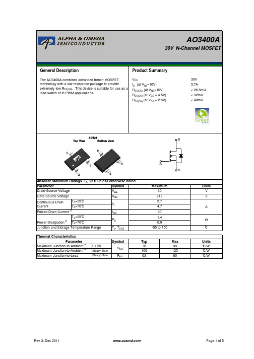
AO3400A 规格书 AOS
AO3400A SOT-23-3L NMOS Vds30V 规格书AO推荐
10µs 100µs 1ms
10ms
0.1
TJ(Max)=150°C
TA=25°C
10s DC
0.0
0.01
0.1
1
10
100
VDS (Volts)
Figure 9: Maximum Forward Biased Safe Operating Area (Note F)
Power (W)
1000 100
ID
Pulsed Drain Current C
IDM
TA=25°C Power Dissipation B TA=70°C
PD
Junction and Storage Temperature Range
TJ, TSTG
G S
Maximum 30 ±12 5.7 4.7 30 1.4 0.9
-55 to 150
In descending order D=0.5, 0.3, 0.1, 0.05, 0.02, 0.01, single pulse
AO3400A
30V N-Channel MOSFET
General Description
Product Summary
The AO3400A combines advanced trench MOSFET technology with a low resistance package to provide extremely low RDS(ON). This device is suitable for use as a load switch or in PWM applications.
B. The power dissipation PD is based on TJ(MAX)=150°C, using ≤ 10s junction-to-ambient thermal resistance. C. Repetitive rating, pulse width limited by junction temperature TJ(MAX)=150°C. Ratings are based on low frequency and duty cycles to keep initialTJ=25°C. D. The RθJA is the sum of the thermal impedence from junction to lead RθJL and lead to ambient. E. The static characteristics in Figures 1 to 6 are obtained using <300µs pulses, duty cycle 0.5% max. F. These curves are based on the junction-to-ambient thermal impedence which is measured with the device mounted on 1in2 FR-4 board with
AO3400 规格书 AOS

VGS=10V
1.8
VGS=4.5V Id=5A 1.6
1.4
17
VGS=105V
1.2
Id=5.8A2
10
1
10
0
5
10
15
20
ID (A)
Figure 3: On-Resistance vs. Drain Current and Gate
Voltage (Note E)
0.8 0
25 50 75 100 125 150 175
In descending order D=0.5, 0.3, 0.1, 0.05, 0.02, 0.01, single pulse
ZθJA Normalized Transient Thermal Resistance
ID(A)
15
VDS=5V 12
9
6
125°C 3
25°C
0
0
0.5
1
1.5
2
2.5
3
VGS(Volts) Figure 2: Transfer Characteristics (Note E)
Normalized On-Resistance
RDS(ON) (mΩ)
30
25 VGS=4.5V
20
15
AO3400
30V N-Channel MOSFET
General Description
Product Summary
The AO3400 combines advanced trench MOSFET technology with a low resistance package to provide extremely low RDS(ON). This device is suitable for use as a load switch or in PWM applications.
AO3434A 规格书 AOS

Thermal Characteristics
Parameter
Symbol
Typ
Maximum Junction-to-Ambient A t ≤ 10s Maximum Junction-to-Ambient A D Steady-State
RθJA
70 100
Maximum Junction-to-Lead
10µs
100µs
1ms 10ms 10s DC
0.0
0.01
0.1
1
10
100
VDS (Volts)
Figure 9: Maximum Forward Biased Safe Operating Area (Note F)
Power (W)
10000 1000
TA=25°C
100
10
1
1E-05
0.001
ns
Qrr
Body Diode Reverse Recovery Charge IF=4A, dI/dt=500A/µs
7.5
nC
A. The value of RθJA is measured with the device mounted on 1in2 FR-4 board with 2oz. Copper, in a still air environment with TA =25°C. The value in any given application depends on the user's specific board design.
Steady-State
RθJL
63
Max 90 125 80
AO3407A 规格书 AOS
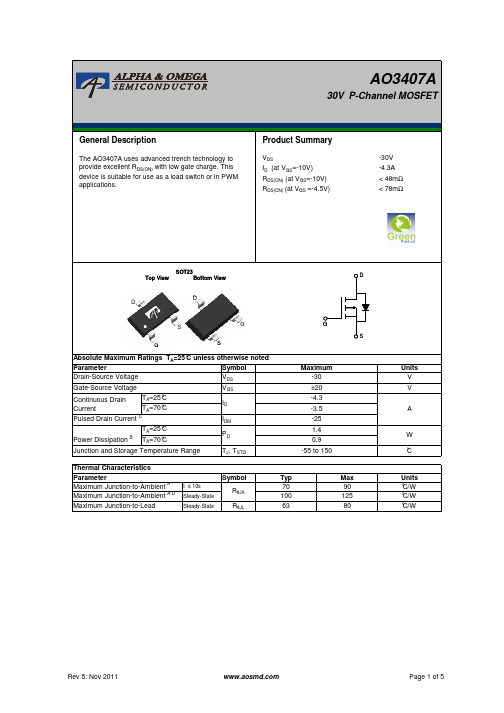
AO3407A30V P-Channel MOSFETGeneral DescriptionThe AO3407A uses advanced trench technology to provide excellent RDS(ON) with low gate charge. This device is suitable for use as a load switch or in PWM applications.Product SummaryVDS ID (at VGS=-10V) RDS(ON) (at VGS=-10V) RDS(ON) (at VGS =-4.5V) -30V -4.3A < 48mΩ < 78mΩSOT23 Top View Bottom ViewDDDS G SGG SAbsolute Maximum Ratings TA=25° C unless otherwise noted Parameter Symbol VDS Drain-Source Voltage Gate-Source Voltage Continuous Drain Current Pulsed Drain Current C TA=25° C Power Dissipation B TA=70° C Junction and Storage Temperature Range Thermal Characteristics Parameter Maximum Junction-to-Ambient A Maximum Junction-to-Ambient A D Maximum Junction-to-Lead TA=25° C TA=70° C VGS ID IDM PD TJ, TSTGMaximum -30 ±20 -4.3 -3.5 -25 1.4 0.9 -55 to 150Units V V AW ° CSymbolt ≤ 10s Steady-State Steady-StateRθJA RθJLTyp 70 100 63Max 90 125 80Units ° C/W ° C/W ° C/WRev 5: Nov 2011Page 1 of 5AO3407AC unless otherwise noted) Electrical Characteristics (TJ=25° Symbol Parameter Conditions ID=-250µA, VGS=0V VDS=-30V, VGS=0V C TJ=55° VDS=0V, VGS= ±20V VDS=VGS ID=-250µA VGS=-10V, VDS=-5V VGS=-10V, ID=-4.3A RDS(ON) gFS VSD IS Static Drain-Source On-Resistance VGS=-4.5V, ID=-3A Forward Transconductance Diode Forward Voltage VDS=-5V, ID=-4.3A IS=-1A,VGS=0V TJ=125° C -1.4 -25 34 52 54 10 -0.7 -1 -2 520 VGS=0V, VDS=-15V, f=1MHz VGS=0V, VDS=0V, f=1MHz 3.5 100 65 7.5 9.2 VGS=-10V, VDS=-15V, ID=-4.3A 4.6 1.6 2.2 7.5 VGS=-10V, VDS=-15V, RL=3.5Ω, RGEN=3Ω IF=-4.3A, dI/dt=100A/µs 5.5 19 7 11 5.3 11.5 11 6 48 68 78 -1.9 Min -30 -1 -5 ±100 -2.4 Typ Max Units V µA nA V A mΩ mΩ S V A pF pF pF Ω nC nC nC nC ns ns ns ns ns nCSTATIC PARAMETERS BVDSS Drain-Source Breakdown Voltage IDSS IGSS VGS(th) ID(ON) Zero Gate Voltage Drain Current Gate-Body leakage current Gate Threshold Voltage On state drain currentMaximum Body-Diode Continuous CurrentDYNAMIC PARAMETERS Input Capacitance Ciss Coss Crss Rg Output Capacitance Reverse Transfer Capacitance Gate resistanceSWITCHING PARAMETERS Qg(10V) Total Gate Charge Qg(4.5V) Total Gate Charge Qgs Qgd tD(on) tr tD(off) tf trr Qrr Gate Source Charge Gate Drain Charge Turn-On DelayTime Turn-On Rise Time Turn-Off DelayTime Turn-Off Fall Time Body Diode Reverse Recovery Time Body Diode Reverse Recovery Charge IF=-4.3A, dI/dt=100A/µsA. The value of RθJA is measured with the device mounted on 1in2 FR-4 board with 2oz. Copper, in a still air environment with TA =25°C. The value in any given application depends on the user's specific board design. B. The power dissipation PD is based on TJ(MAX)=150°C, using ≤ 10s junction-to-ambient thermal resistance. C. Repetitive rating, pulse width limited by junction temperature TJ(MAX)=150°C. Ratings are based on low frequency and duty cycles to keep initialTJ=25°C. D. The RθJA is the sum of the thermal impedence from junction to lead RθJL and lead to ambient. E. The static characteristics in Figures 1 to 6 are obtained using <300µs pulses, duty cycle 0.5% max. F. These curves are based on the junction-to-ambient thermal impedence which is measured with the device mounted on 1in2 FR-4 board with 2oz. Copper, assuming a maximum junction temperature of TJ(MAX)=150°C. The SOA curve provides a single pulse rating.THIS PRODUCT HAS BEEN DESIGNED AND QUALIFIED FOR THE CONSUMER MARKET. APPLICATIONS OR USES AS CRITICAL COMPONENTS IN LIFE SUPPORT DEVICES OR SYSTEMS ARE NOT AUTHORIZED. AOS DOES NOT ASSUME ANY LIABILITY ARISING OUT OF SUCH APPLICATIONS OR USES OF ITS PRODUCTS. AOS RESERVES THE RIGHT TO IMPROVE PRODUCT DESIGN, FUNCTIONS AND RELIABILITY WITHOUT NOTICE.Rev 5: Nov 2011Page 2 of 5AO3407ATYPICAL ELECTRICAL AND THERMAL CHARACTERISTICS30 25 -10V 20 -ID (A) 15 -4V 10 5 0 0 1 2 3 4 5 -VDS (Volts) Fig 1: On-Region Characteristics (Note E) 80 Normalized On-Resistance 70 60 RDS(ON) (mΩ ) 50 40 30 20 10 0 6 8 10 -ID (A) Figure 3: On-Resistance vs. Drain Current and Gate Voltage (Note E) 2 4 VGS=-10V VGS=-4.5V VGS=-3.5V 10 5 0 0.5 1.5 2.5 3.5 4.5 5.5 -VGS(Volts) Figure 2: Transfer Characteristics (Note E) 125°C 25°C -4.5V 20 -ID(A) 15 -6V 25 30 VDS=-5V1.8 1.6 1.4 1.2 1 0.8 0 25 50 75 100 125 150 175 VGS=-10V ID=-4.3AVGS ID=-3A17 5 2 10 =-4.5V0 Temperature (° C) Figure 4: On-Resistance vs. Junction Temperature 18 (Note E)120 ID=-4.3A 100 RDS(ON) (mΩ )1.0E+02 1.0E+01 1.0E+00 -IS (A)4080 125°C 60125°C 1.0E-01 1.0E-02 1.0E-0325°C4025°C1.0E-04 1.0E-0520 6 8 10 -VGS (Volts) Figure 5: On-Resistance vs. Gate-Source Voltage (Note E) 2 40.00.20.40.60.81.01.2-VSD (Volts) Figure 6: Body-Diode Characteristics (Note E)Rev 5: Nov 2011Page 3 of 5AO3407ATYPICAL ELECTRICAL AND THERMAL CHARACTERISTICS10 VDS=-15V ID=-4.3A 600 6 Capacitance (pF) -VGS (Volts) Ciss 80084004Coss 2002 Crss 0 5 10 15 20 25 -VDS (Volts) Figure 8: Capacitance Characteristics 300 0 2 4 6 8 Qg (nC) Figure 7: Gate-Charge Characteristics 100100.040 TA=25°C10.010µsPower (W)30ID (Amps)RDS(ON) limited1.0100µs 1ms 10ms 10ms200.1TJ(Max)=150°C TA=25°C10s DC100.0 0.01 0.1 1 VDS (Volts) 10 1000 0.0001 1 100 Pulse Width (s) Figure 10: Single Pulse Power Rating Junction-toAmbient (Note F) 0.01Figure 9: Maximum Forward Biased Safe Operating Area (Note F)10 Zθ JA Normalized Transient Thermal Resistance D=Ton/T TJ,PK=TA+PDM.ZθJA.RθJA 1 RθJA=125°C/WIn descending order D=0.5, 0.3, 0.1, 0.05, 0.02, 0.01, single pulse0.1 PD 0.01 Single Pulse Ton 0.001 0.00001 0.0001 0.001 0.01 0.1 1 10 100 1000 Pulse Width (s) Figure 11: Normalized Maximum Transient Thermal Impedance (Note F) PD Ton T TRev 5: Nov 2011Page 4 of 5AO3407AGate Charge Test Circuit & WaveformVgs Qg -10VVDCVDCDUT Vgs IgResistive Switching Test Circuit & WaveformsRL Vds Vgs Vgs Rg DUTVDCVgs VdsDiode Recovery Test Circuit & WaveformsVds + DUT Vgst rrVds Isd Vgs IgLVDC+ Vdd -VdsRev 5: Nov 2011+Chargeton td(on) tr t d(off) toff tf+--+-VdsQgsQgdVdd90%10%Q rr = - Idt-Isd-I FdI/dt -I RM VddPage 5 of 5。
AO3400 SOT-23-3L NMOS Vds30V 规格书AO推荐

ID(A)
15
VDS=5V 12
9
6
125°C 3
25°C
0
0
0.5
1
1.5
2
2.5
3
VGS(Volts) Figure 2: Transfer Characteristics (Note E)
Normalized On-Resistance
RDS(ON) (mΩ)
30
25 VGS=4.5V
20
15
Symbol
Parameter
Conditions
Min Typ Max Units
STATIC PARAMETERS
BVDSS Drain-Source Breakdown Voltage
ID=250µA, VGS=0V
30
V
IDSS
Zero Gate Voltage Drain Current
VDS=30V, VGS=0V
Parameter
Symbol
Drain-Source Voltage
VDS
Gate-Source Voltage
VGS
Continuous Drain Current
TA=25°C TA=70°C
ID
Pulsed Drain Current C
IDM
TA=25°C Power Dissipation B TA=70°C
(Note E)
IS (A)
1.0E+01
1.0E+00
40
1.0E-01
1.0E-02
1.0E-03
125°C
25°C
1.0E-04
1.0E-05
AO3400A参数资料

AO3400A参数资料1.尺寸参数:-封装类型:SOT-23- 封装尺寸:2.9mm x 1.3mm x 1.0mm-引脚数量:3-引脚排列方式:晶体管源极、漏极和栅极分别对应引脚1、2和3 2.电气特性:-额定电压:VDSS=30V(漏-源开路时的电压)-额定电流:ID=4.3A(栅源电压VGS=10V)-导通电阻:RDS(ON)=52mΩ(栅源电压VGS=10V)-静态偏置参数:VGS(TH)=1.3V(栅源阈值电压)-最大功率耗散:PD=1.25W(封装为SOT-23)-反向漏极电压:VDS=-30V-栅源电压范围:VGS=±20V-工作温度范围:-55℃至150℃-电荷耦合特性:Qg=9.4nC(栅源电压VGS=10V)- 总电荷积(总门电荷):Qgd = 5nC(栅源电压VGS = 10V)3.功能特点:-低导通电阻:AO3400A采用先进的N沟道MOSFET技术,具有较低的导通电阻,能够实现更低的功耗和更高的效率。
-快速开关速度:由于器件尺寸较小,AO3400A具有快速的开关速度,能够实现快速的功率开关应用。
-低阈值电压:器件的栅源阈值电压较低,为1.3V,能够灵活控制器件的导通状态。
-低输入电荷:AO3400A的总电荷积(总门电荷)较小,仅为5nC,能够实现快速的响应速度和低功耗设计。
4.主要应用:-电源管理:AO3400A可以应用于电源开关、DC-DC转换器、电池管理等领域,实现高效的电源管理和功率转换。
-低功耗设备:由于AO3400A具有低阈值电压和低导通电阻,可以用于手机、平板电脑、手持设备等低功耗设备的功率开关和控制。
-电机驱动:AO3400A能够提供高电流和低导通电阻,适用于小型电机驱动器,如风扇、小型电动工具等领域。
总之,AO3400A是一种N沟道增强型MOSFET,具有小尺寸、低功耗和快速开关速度的特点。
它可以应用于电源管理、低功耗设备和电机驱动等领域,满足高效率、低功耗和高速开关的设计需求。
ao3400中文资料

O3400a数据手册规格AO3401A中文信息PDF)MOS晶体管-MOS管测试步骤:5:MOS晶体管的Gate AOS公司MOS管7407导线的连接使栅极电荷释放,内部电场消失,导电沟道消失,因此漏极和源极之间的电阻变得无限大。
此时,用一根导线连接被测管的栅极和源,万用表的指针将立即返回无穷大,如图5-6所示。
6:MOS晶体管源AOS半导体MOS晶体管74117:VDMOS,MOSFET,osmos晶体管MOS 7413(ao3400a数据手册规格AO3401A中文信息PDF)MOS晶体管8:MESFET如何工作AOS模拟开关MOS 74159:双栅极MOSFET AOSTVS二极管MOS晶体管7417如果去除了电阻,则探针将逐渐恢复为高电阻甚至无限大,因此应考虑被测管的栅极泄漏。
此时处于图5-4的状态;然后将连接的电阻移开,然后万用表的指针仍应为MOS晶体管导通指数保持不变,如图5-5所示。
尽管去除了电阻,但是由于由电阻充电至栅极的电荷不会消失,因此栅极电场继续保持,内部导电沟道保持不变,这是绝缘栅MOS晶体管的特性。
10:功率MOSFET有源模块MOS管740111:电子零件MOS管7405(ao3400a数据手册规格AO3401A中文信息PDF)MOS晶体管12:AOS公司的MOS FET参数MOS 780013:用于MOS FET的AOS半导体MOS晶体管7801此时,使用100k-200k电阻连接栅极和漏极,如图5-4所示。
此时,欧姆越小越好。
通常,它可以指示0欧姆。
此时,正电荷通过100k电阻为高功率MOS晶体管的栅极充电,以产生栅极电场。
随着电场的产生,导电通道导致漏极和源极连接,因此万用表指针会偏转并偏转角度。
高度(小欧姆指数)表示良好的放电性能。
14:MOSFET AOS代理MOS晶体管340015:什么是场效应管MOS晶体管3400a(ao3400a数据手册规格AO3401A中文信息PDF)MOS晶体管16:什么是MOS晶体管MOS晶体管340217:MOSFET的基础知识MOS晶体管3404将红色探针连接到MOS晶体管的源极,将黑色探针连接到MOS晶体管的漏极D。
ao3400中文资料

ao3400中文资料场效应管(Field Effect Transistor,缩写FET)是场效应晶体管的简称,是利用控制输入回路的电场效应来控制输出回路电流的一种半导体器件。
它主要有两种类型:结型场效应管和金属- 氧化物半导体场效应管,具有输入电阻高(107~1015Ω)、噪声小、功耗低、动态范围大、易于集成、没有二次击穿现象等优点。
与双极型晶体管相比,场效应管具有如下特点。
(1)场效应管是电压控制器件,它通过VGS(栅源电压)来控制ID(漏极电流);(2)场效应管的控制输入端电流极小,因此它的输入电阻(107~1012Ω)很大。
(3)它是利用多数载流子导电,因此它的温度稳定性较好;(4)它组成的放大电路的电压放大系数要小于三极管组成放大电路的电压放大系数;(5)场效应管的抗辐射能力强;(6)由于它不存在杂乱运动的电子扩散引起的散粒噪声,所以噪声低。
场效应管工作原理用一句话说,就是“漏极-源极间流经沟道的ID,用以栅极与沟道间的pn结形成的反偏的栅极电压控制ID”。
更正确地说,ID流经通路的宽度,即沟道截面积,它是由pn结反偏的变化,产生耗尽层扩展变化控制的缘故。
在VGS=0的非饱和区域,表示的过渡层的扩展因为不很大,根据漏极-源极间所加VDS的电场,源极区域的某些电子被漏极拉去,即从漏极向源极有电流ID流动。
从门极向漏极扩展的过度层将沟道的一部分构成堵塞型,ID饱和。
将这种状态称为夹断。
这意味着过渡层将沟道的一部分阻挡,并不是电流被切断。
在过渡层由于没有电子、空穴的自由移动,在理想状态下几乎具有绝缘特性,通常电流也难流动。
但是此时漏极-源极间的电场,实际上是两个过渡层接触漏极与门极下部附近,由于漂移电场拉去的高速电子通过过渡层。
因漂移电场的强度几乎不变产生ID的饱和现象。
其次,VGS向负的方向变化,让VGS=VGS(off),此时过渡层大致成为覆盖全区域的状态。
而且VDS的电场大部分加到过渡层上,将电子拉向漂移方向的电场,只有靠近源极的很短部分,这更使电流不能流通。
ao3400中文资料

ao3400中文资料半导体(Semiconductor)是一种电导率在绝缘体至导体之间的物质,其电导率容易受控制,可作为信息处理的元件材料。
从科技或是经济发展的角度来看,半导体非常重要。
很多电子产品,如计算机、移动电话、数字录音机的核心单元都是利用半导体的电导率变化来处理信息。
常见的半导体材料有硅、锗、砷化镓等,而硅更是各种半导体材料中,在商业应用上最具有影响力的一种。
顾名思义:常温下导电性能介于导体(conductor)与绝缘体(insulator)之间的材料,叫做半导体(semiconductor)。
物质存在的形式多种多样,固体、液体、气体、等离子体等等。
我们通常把导电性和导电导热性差或不好的材料,如金刚石、人工晶体、琥珀、陶瓷等等,称为绝缘体。
而把导电、导热都比较好的金属如金、银、铜、铁、锡、铝等称为导体。
可以简单的把介于导体和绝缘体之间的材料称为半导体。
与导体和绝缘体相比,半导体材料的发现是最晚的,直到20世纪30年代,当材料的提纯技术改进以后,半导体的存在才真正被学术界认可。
半导体的分类,按照其制造技术可以分为:集成电路器件,分立器件、光电半导体、逻辑IC、模拟IC、储存器等大类,一般来说这些还会被分成小类。
此外还有以应用领域、设计方法等进行分类,虽然不常用,单还是按照IC、LSI、VLSI(超大LSI)及其规模进行分类的方法。
此外,还有按照其所处理的信号,可以分成模拟、数字、模拟数字混成及功能进行分类的方法。
基本定义电阻率介于金属和绝缘体之间并有负的电阻温度系数的物质。
半导体室温时电阻率约在10E-5~10E7欧·米之间,温度升高时电阻率指数则减小。
半导体材料很多,按化学成分可分为元素半导体和化合物半导体两大类。
锗和硅是最常用的元素半导体;化合物半导体包括Ⅲ-Ⅴ 族化合物(砷化镓、磷化镓等)、Ⅱ-Ⅵ族化合物( 硫化镉、硫化锌等)、氧化物(锰、铬、铁、铜的氧化物),以及由Ⅲ-Ⅴ族化合物和Ⅱ-Ⅵ族化合物组成的固溶体(镓铝砷、镓砷磷等)。
AOS美国万代全系列产品参数大全

ID (A) 0.04 5.8 5.7 -4 -4 4 -2.6 5 5.8 3.6 -4.1 -4.3 -2.6 -3 3 -4 -4 6.5 3.8 -3.5 6 -2.6 2.1 -2 3.8 3.5 -2.9 3 0.5 --6 8.5 -6 11.5 13 -12 -12 -15 18 -8 -15 -8 -9.7 13.7 13.7 -6.2 -17 -14 0.03 4.9 4.7 -3.2 -3.2 3.2 -2.2 4 4.9 2.9 -3.5 -3.5 -2.2 -2.4 2.5 -3.5 -3.5 5.2 3.1 -2.8 5 -2.2 1.7 -2 3.1 2.8 -2.3 2.5 1.6 -2.3 19 15 14 18 14 22 18 16 16 -5 7.1 -5.1 9.6 10.4 -10 -10 -13 15 -6.6 -13 -6.6 -7.8 9.7 9.7 -5 -14 -11
-30 30 -30 -30 -12 60 60 -60 75 -40 80 30 -30 -30 80 -30 40 100 100 -30 30 30 30 30 30 40 100 40 -40 100 30 30 30 30 30 30 30 30 -30 30 -30 30 60 -60 60 -60 -30 30 -40 40 -40 40 -30 30 -40 40 -40 40 -30
Qgd (nC) 0.52* 1.8 1.8 2.5 2.5 1.6 1 1.3 1.7 1 2.2 2.2 1.1 2.1 0.6 2.2 2.2 2.6 1.6 1.1 2 1.1 0.8 0.9 1.6 0.65 2.1 0.6 1.9 8 4.2 8.5 10.9 5.6 6.2 4.7 3.2 12 2.5 1.8 2.2 5.5 3 10 10.4 23 16.8 3.2 16 5.2 4.6 8.6 8.6 9.2 14 16.1
AOS选型表
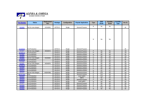
AO3400Not for new designs AO3400A SOT23-3Single General Purpose N No No 30AO3400A Full ProductionSOT23-3Single General Purpose N No No 30AO3401Not for new designs AO3401ASOT23-3Single General Purpose P No No -30AO3401A Full Production SOT23-3Single General Purpose P No No -30AO3402Full Production SOT23-3Single General Purpose N No No 30AO3403Full ProductionSOT23-3Single General Purpose P No No -30AO3404Not for new designs AO3404ASOT23-3Single General Purpose N No No 30AO3404A Full Production SOT23-3Single General Purpose N No No 30AO3406Full ProductionSOT23-3Single General Purpose N No No 30AO3407Not for new designs AO3407ASOT23-3Single General Purpose P No No -30AO3407A Full Production SOT23-3Single General Purpose P No No -30AO3409Full Production SOT23-3Single General Purpose P No No -30AO3413Full Production SOT23-3Single General Purpose P No No -20AO3414Full ProductionSOT23-3Single General Purpose N No No 20AO3415Not for new designs AO3415ALSOT23-3Single General Purpose P Yes No -20AO3415AL NewSOT23-3Single General Purpose P Yes No -20AO3416Full Production SOT23-3Single Load Switch N Yes No 20AO3418Full Production SOT23-3Single SMPSN No No 30AO3419Full Production SOT23-3Single General Purpose P Yes No -20AO3420Full Production SOT23-3Single Load Switch N No No 20AO3421Full Production SOT23-3Single General Purpose P No No -30AO3422Full Production SOT23-3Single General Purpose N No No 55AO3423Full Production SOT23-3Single General Purpose P Yes No -20AO3424Full Production SOT23-3Single General Purpose N No No 30AO3434Full Production SOT23-3Single Battery ProtectionN Yes No 30AO3435NewSOT23-3Single SMPS P No No -20AO3438Full Production SOT23-3Single Load Switch N No No 20AO3460Full Production SOT23-3Single Load Switch N Yes No 60AO3700Full Production SOT23-5Single General Purpose N Yes No 30AO3701Full Production SOT23-5Single General Purpose P Yes No -20AO3702Full Production SOT23-5Single General Purpose N No Yes 0.5A 20AO3703Full Production SOT23-5Single General PurposeP No Yes 0.5A -20AO3705New SOT23-5Single SMPSP No Yes 1A-20AO4202L New SO-8Single SMPS Low Side N No No 30AO4402LNewSO-8SingleLoad SwitchNNoNo20Type ESD Diode Schottky Diode Schottky TypeV DS (V)Part Number StatusReplacementPart Package ConfigurationPopular Application* indicate Qg at 10VFor all bottom exposed packages, the Id and Pd are calculated at 100°C, otherwise are calculated at 70°C.。
aos万代mos管选型与替换
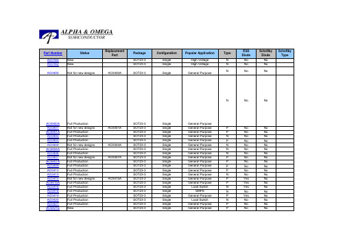
AO3160New SOT23-3Single High Voltage N No No AO3162NewSOT23-3Single High Voltage N No No AO3400Not for new designs AO3400A SOT23-3SingleGeneral PurposeNNoNoAO3400A Full ProductionSOT23-3Single General Purpose N No NoAO3401Not for new designs AO3401ASOT23-3Single General Purpose P No No AO3401A Full Production SOT23-3Single General Purpose P No No AO3402Full Production SOT23-3Single General Purpose N No No AO3403Full ProductionSOT23-3Single General Purpose P No No AO3404Not for new designs AO3404ASOT23-3Single General Purpose N No No AO3404A Full Production SOT23-3Single General Purpose N No No AO3406Full ProductionSOT23-3Single General Purpose N No No AO3407Not for new designs AO3407ASOT23-3Single General Purpose P No No AO3407A Full Production SOT23-3Single General Purpose P No No AO3409Full Production SOT23-3Single General Purpose P No No AO3413Full Production SOT23-3Single General Purpose P No No AO3414Full ProductionSOT23-3Single General Purpose N No No AO3415Not for new designs AO3415ASOT23-3Single General Purpose P Yes No AO3415A Full Production SOT23-3Single General Purpose P Yes No AO3416Full Production SOT23-3Single Load Switch N Yes No AO3418Full Production SOT23-3Single SMPSN No No AO3419Full Production SOT23-3Single General Purpose P Yes No AO3420Full Production SOT23-3Single Load Switch N No No AO3421Full Production SOT23-3Single General Purpose P No No AO3421E NewSOT23-3Single General PurposeP No NoConfigurationPopular ApplicationType Part Number StatusReplacementPartPackage ESD Diode Schottky Diode Schottky Type车载DVD、笔记本电脑、PDA、电源、稳压器、逆变器、高压条、适配器、数码相机、电子游戏机、电子玩具等多重数码产品尚晶是鼎日MOS 管 中国总代代理,进口原装品质,超低的价格和稳定的供货,可免费提供样品测试。
AO3400_datasheet
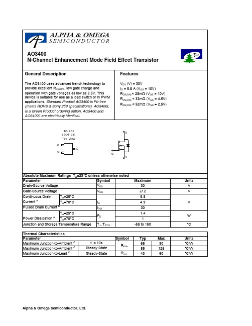
SymbolTyp Max 659085125R θJL 4360Maximum Junction-to-LeadCSteady-State°C/WThermal Characteristics ParameterUnits Maximum Junction-to-AmbientAt ≤ 10s R θJA °C/W Maximum Junction-to-AmbientASteady-State °C/W AO3400SymbolMin TypMaxUnits BV DSS 30V 1T J =55°C5I GSS 100nA V GS(th)0.7 1.11.4V I D(ON)30A 22.828T J =125°C323927.333m Ω43.352m Ωg FS 1015S V SD 0.711V I S2.5A C iss 8231030pF C oss 99pF C rss 77pF R g1.2 3.6ΩQ g 9.712nC Q gs 1.6nC Q gd 3.1nC t D(on) 3.35ns t r 4.87ns t D(off)26.340ns t f 4.16ns t rr 1620ns Q rr8.912nCTHIS PRODUCT HAS BEEN DESIGNED AND QUALIFIED FOR THE CONSUMER MARKET. APPLICATIONS OR USES AS CRITICAL COMPONENTS IN LIFE SUPPORT DEVICES OR SYSTEMS ARE NOT AUTHORIZED. AOS DOES NOT ASSUME ANY LIABILITY ARISING OUT OF SUCH APPLICATIONS OR USES OF ITS PRODUCTS. AOS RESERVES THE RIGHT TO IMPROVE PRODUCT DESIGN,FUNCTIONS AND RELIABILITY WITHOUT NOTICE.Gate resistanceV GS =0V, V DS =0V, f=1MHzTurn-Off Fall TimeMaximum Body-Diode Continuous CurrentInput Capacitance Output Capacitance Turn-On DelayTime DYNAMIC PARAMETERS I F =5A, dI/dt=100A/µsV GS =0V, V DS =15V, f=1MHz SWITCHING PARAMETERS Total Gate Charge V GS =4.5V, V DS =15V, I D =5.8AGate Source Charge Gate Drain Charge Turn-On Rise Time Turn-Off DelayTime V GS =10V, V DS =15V, R L =2.7Ω, R GEN =3Ωm ΩV GS =4.5V, I D =5A I S =1A,V GS =0V V DS =5V, I D =5AR DS(ON)Static Drain-Source On-ResistanceForward TransconductanceDiode Forward VoltageI DSS µA Gate Threshold Voltage V DS =V GS I D =250µA V DS =24V, V GS =0VV DS =0V, V GS =±12V Zero Gate Voltage Drain Current Gate-Body leakage current Electrical Characteristics (T J =25°C unless otherwise noted)STATIC PARAMETERS ParameterConditions Body Diode Reverse Recovery TimeBody Diode Reverse Recovery Charge I F =5A, dI/dt=100A/µsDrain-Source Breakdown Voltage On state drain currentI D =250µA, V GS =0V V GS =2.5V, I D =4AV GS =4.5V, V DS =5V V GS =10V, I D =5.8AReverse Transfer Capacitance A: The value of R θJA is measured with the device mounted on 1in 2 FR-4 board with 2oz. Copper, in a still air environment with T A =25°C. The value in any given application depends on the user's specific board design. The current rating is based on the t ≤ 10s thermal resistance rating.B: Repetitive rating, pulse width limited by junction temperature.C. The R θJA is the sum of the thermal impedence from junction to lead R θJL and lead to ambient.D. The static characteristics in Figures 1 to 6,12,14 are obtained using 80 µs pulses, duty cycle 0.5% max.E. These tests are performed with the device mounted on 1 in 2FR-4 board with 2oz. Copper, in a still air environment with T A =25°C. The SOA curve provides a single pulse rating. Rev 4 : June 2005。
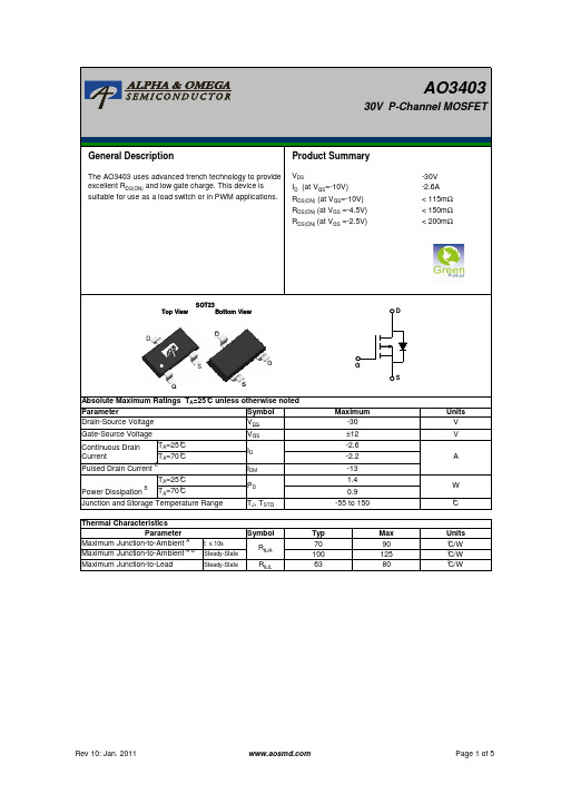
AO3403 规格书 AOS
RDS(ON) (mΩ)
250
200
150
100
25°C
ID=-2.6A 125°C
50
0
2
4
6
8
10
-VGS (Volts) Figure 5: On-Resistance vs. Gate-Source Voltage
(Note E)
-IS (A)
1.0E+02
1.0E+01
40
VDS ID (at VGS=-10V) RDS(ON) (at VGS=-10V) RDS(ON) (at VGS =-4.5V) RDS(ON) (at VGS =-2.5V)
-30V -2.6A < 115mΩ < 150mΩ < 200mΩ
SOT23
Top View
Bottom View
D
D D
S
G
G
S
Absolute Maximum Ratings TA=25°C unless otherwise noted
Parameter
Symbol
Drain-Source Voltage
VDS
Gate-Source Voltage
VGS
Continuous Drain Current
TA=25°C TA=70°C
RDS(ON) (mΩ)
210
190
VGS=-2.5V
170
150
130
VGS=-4.5V
110
90
70
VGS=-10V
50
0
1
2
3
4
5
ao3400中文资料
ao3400中文资料AO3400A器件“身份信息”:•厂商:AOS•包装说明:SO, R-PDSO-G3•针数:3•REACH法规/ RoHS合规数据:符合Rohs认证,不含铅,符合REACH法规•最小漏源击穿电压:30V•最大漏极电流(ID):5.7A•功率- 最大值:1.4W•装类型:表面贴装•FET 类型:MOSFET N 通道,金属氧化物•FET 功能:逻辑电平栅极,2.5V 驱动•应用场景:AO3400A结合了先进的沟道MOSFET低电阻封装技术极低的RDS(开)。
此设备适合用作负载开关或在PWM应用中。
原理图符号印刷电路板封装3D2FE 功能等同认证替代料感觉这款器件跟你的设计不那么匹配还差点意思?根据FFF 形态、装配、功能兼容替代料等方面,推荐7种不同厂商的替代料,来做下全部参数和差异参数的对比,总有一款适合你。
或者挑选部分替代料对比3价格and 库存不看器件价格和库存的工程师,不是称职的工程师,从分销商库存以及市场的价格走势来看,过去半年中,AO3400A的价格是有略微降低的,但是库存量却在大幅度增长(不然说它热门呢!)其中97%的市场库存量都在Digi-Key,其次是唯样、艾睿。
AO3400A过去半年价格和库存走势4参考设计案例开源基于STC15W4K61S4的微型四旋翼,参考设计送上,拿走不谢!功能概述:本设计是基于STC15W4K61S4的微型四轴。
以STC15W4K61S4为主控。
硬件包括,MPU6050传感器,电源,NRF2401通信模块,720空心杯电机,PCB机架。
姿态解算采用四元数,串级PID作为控制器,配合遥控器实现俯仰,横滚,偏航姿态控制。
主要用于学习和理解四轴飞行器的基本原理。
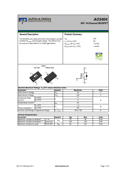
AO3404 规格书 AOS
Power (W)
10000 1000
TA=25°C
100
10
1
0.00001 0.001
0.1
10
1000
Pulse Width (s) Figure 11: Single Pulse Power Rating Junction-to-
Ambient (Note F)
In descending order D=0.5, 0.3, 0.1, 0.05, 0.02, 0.01, single pulse
Ciss
Input Capacitance
Coss
Output Capacitance
Crss
Reverse Transfer Capacitance
Rg
Gate resistance
VGS=0V, VDS=15V, f=1MHz VGS=0V, VDS=0V, f=1MHz
255 310 pF
45
AO3404
30V N-Channel MOSFET
General Description
Product Summary
The AO3404 uses advanced trench technology to provide excellent RDS(ON) and low gate charge. This device may be used as a load switch or in PWM applications.
ID=-250µA, VGS=0V
30
IDSS
Zero Gate Voltage Drain Current
VDS=30V, VGS=0V
TJ=55°C
艾森KG3400A09S41型号电路保护器说明书

Eaton KG3400A09S41Eaton Series C complete molded case circuit breaker, K-frame, KG, Thermal-magnetic trip, 1000-2000A trip rating, Three-pole, 400A, 600 Vac, 2A-2B same side w/ left pigtail, 12-24 Vac/dc same side w/ left pigtailGeneral specificationsEaton Series C complete molded case circuit breakerKG3400A09S4178668526677014.75 in 6.2 in6.2 in 13.24 lb Eaton Selling Policy 25-000, one (1) year from the date of installation of the Product or eighteen (18) months from the date of shipment of the Product, whichever occurs first.IEC 947-2 CSA Std. C22.2 No. 5UL 489Product NameCatalog Number UPCProduct Length/Depth Product Height Product Width Product Weight WarrantyCertifications14 kAIC at 480 Vac18 kAIC at 240 VacK144 kVA/116 kW at 240 Vac, 289 kVA/231 kW at 480 Vac, 361 kVA/289 kW at 600 Vac1000-2000 AReverse400 AThree-poleKG12-24 Vac/dc left pigtail same side60 HzEngine generatorComplete breakerLine and load600 Vac2A-2B same side with left pigtailThermal-magnetic Application of Tap Rules to Molded Case Breaker TerminalsUL listed 100%-rated molded case circuit breakersApplication of Multi-Wire Terminals for Molded Case Circuit BreakersCircuit breaker motor operators product aidPower metering and monitoring with Modbus RTU product aid StrandAble terminals product aidMulti-wire lugs product aidCurrent limiting Series C molded case circuit breakers product aid Plug-in adapters for molded case circuit breakers product aidMotor protection circuit breakers product aidBreaker service centersEaton's Volume 4—Circuit ProtectionMolded case circuit breakers catalogSeries C Engine Generator Circuit Breakers - Dimension SheetsCircuit Breakers ExplainedCircuit breakers explainedEaton Specification Sheet - KG3400A09S41Series C G-Frame molded case circuit breakers time current curves MOEM MCCB product selection guideSeries C J-Frame molded case circuit breakers time current curves Series C F-Frame molded case circuit breakersInterrupt ratingFrameGenerator ratingTrip ratingFunctionsAmperage Rating Number of polesCircuit breaker type Shunt tripFrequency ratingClassCircuit breaker frame type TerminalsVoltage ratingAuxiliary switchTrip Type Application notesBrochuresCatalogsDrawingsMultimediaSpecifications and datasheetsEaton Corporation plc Eaton House30 Pembroke Road Dublin 4, Ireland © 2023 Eaton. All Rights Reserved. Eaton is a registered trademark.All other trademarks areproperty of their respectiveowners./socialmedia。
- 1、下载文档前请自行甄别文档内容的完整性,平台不提供额外的编辑、内容补充、找答案等附加服务。
- 2、"仅部分预览"的文档,不可在线预览部分如存在完整性等问题,可反馈申请退款(可完整预览的文档不适用该条件!)。
- 3、如文档侵犯您的权益,请联系客服反馈,我们会尽快为您处理(人工客服工作时间:9:00-18:30)。
ID(A)
15
VDS=5V 12
9
6
125°C 3
25°C
0
0
0.5
1
1.5
2
2.5
3
VGS(Volts) Figure 2: Transfer Characteristics (Note E)
Normalized On-Resistance
RDS(ON) (mΩ)
30
25 VGS=4.5V
20
15
S
Absolute Maximum Ratings TA=25°C unless otherwise noted
Parameter
Symbol
Drain-Source Voltage
VDS
Gate-Source Voltage
VGS
Continuous Drain Current
TA=25°C TA=70°C
Crss
Reverse Transfer Capacitance
Rg
Gate resistance
VGS=0V, VDS=15V, f=1MHz VGS=0V, VDS=0V, f=1MHz
630
pF
75
pF
50
pF
1.5
3
4.5
Ω
SWITCHING PARAMETERS
Qg
Total Gate Charge
B. The power dissipation PD is based on TJ(MAX)=150°C, using ≤ 10s junction-to-ambient thermal resistance. C. Repetitive rating, pulse width limited by junction temperature TJ(MAX)=150°C. Ratings are based on low frequency and duty cycles to keep initialTJ=25°C. D. The RθJA is the sum of the thermal impedence from junction to lead RθJL and lead to ambient. E. The static characteristics in Figures 1 to 6 are obtained using <300µs pulses, duty cycle 0.5% max. F. These curves are based on the junction-to-ambient thermal impedence which is measured with the device mounted on 1in2 FR-4 board with
2.6
nC
A. The value of RθJA is measured with the device mounted on 1in2 FR-4 board with 2oz. Copper, in a still air environment with TA =25°C. The value in any given application depends on the user's specific board design.
Symbol
Parameter
Conditions
Min Typ Max Units
STATIC PARAMETERS
BVDSS Drain-Source Breakdown Voltage
ID=250µA, VGS=0V
3age Drain Current
VDS=30V, VGS=0V
2oz. Copper, assuming a maximum junction temperature of TJ(MAX)=150°C. The SOA curve provides a single pulse rating.
THIS PRODUCT HAS BEEN DESIGNED AND QUALIFIED FOR THE CONSUMER MARKET. APPLICATIONS OR USES AS CRITICAL COMPONENTS IN LIFE SUPPORT DEVICES OR SYSTEMS ARE NOT AUTHORIZED. AOS DOES NOT ASSUME ANY LIABILITY ARISING OUT OF SUCH APPLICATIONS OR USES OF ITS PRODUCTS. AOS RESERVES THE RIGHT TO IMPROVE PRODUCT DESIGN, FUNCTIONS AND RELIABILITY WITHOUT NOTICE.
VGS=10V
1.8
VGS=4.5V
1.6
ID=5A
1.4
17
VGS=105V
1.2
ID=5.7A2
10
1
10
0
5
10
15
20
ID (A)
Figure 3: On-Resistance vs. Drain Current and Gate
Voltage (Note E)
0.8 0
25 50 75 100 125 150 175
10µs 100µs 1ms
10ms
0.1
TJ(Max)=150°C
TA=25°C
10s DC
0.0
0.01
0.1
1
10
100
VDS (Volts)
Figure 9: Maximum Forward Biased Safe Operating Area (Note F)
Power (W)
1000 100
Steady-State
RθJL
63
Max 90 125 80
Units V V
A
W °C
Units °C/W °C/W °C/W
Rev 3: Dec 2011
Page 1 of 5
AO3400A
Electrical Characteristics (TJ=25°C unless otherwise noted)
Page 3 of 5
AO3400A
TYPICAL ELECTRICAL AND THERMAL CHARACTERISTICS
5
VDS=15V ID=5.7A 4
1000
800 Ciss
3
600
Capacitance (pF)
VGS (Volts)
ID (Amps)
2
1
Thermal Characteristics
Parameter
Symbol
Typ
Maximum Junction-to-Ambient A t ≤ 10s Maximum Junction-to-Ambient A D Steady-State
RθJA
70 100
Maximum Junction-to-Lead
VDS ID (at VGS=10V) RDS(ON) (at VGS=10V) RDS(ON) (at VGS = 4.5V) RDS(ON) (at VGS = 2.5V)
30V 5.7A < 26.5mΩ < 32mΩ < 48mΩ
SOT23
Top View
Bottom View
D
D D
S
G
G
2.5
ns
tD(off)
Turn-Off DelayTime
RGEN=3Ω
25
ns
tf
Turn-Off Fall Time
4
ns
trr
Body Diode Reverse Recovery Time IF=5.7A, dI/dt=100A/µs
8.5
ns
Qrr
Body Diode Reverse Recovery Charge IF=5.7A, dI/dt=100A/µs
TJ=55°C
1 µA
5
IGSS
Gate-Body leakage current
VDS=0V, VGS= ±12V
100 nA
VGS(th) Gate Threshold Voltage
VDS=VGS ID=250µA
0.65 1.05 1.45 V
ID(ON)
On state drain current
Rev 3: Dec 2011
Page 2 of 5
AO3400A
TYPICAL ELECTRICAL AND THERMAL CHARACTERISTICS
ID (A)
40 10V
35
30
3V 4.5V
25
2.5V
20
15
10 VGS=2V
5
0
0
1
2
3
4
5
VDS (Volts) Fig 1: On-Region Characteristics (Note E)
In descending order D=0.5, 0.3, 0.1, 0.05, 0.02, 0.01, single pulse
VGS=4.5V, VDS=5V
30
A
RDS(ON) Static Drain-Source On-Resistance
VGS=10V, ID=5.7A VGS=4.5V, ID=5A
TJ=125°C
18 26.5
mΩ
28
