QuickStart-快速入门
Yocto Project Quick Start-v2.2(中文版)

目录欢迎 (2)Yocto项目开发环境介绍 (2)Yocto项目特点: (3)从建立到使用Yocto Project (3)Linux发行版本: (3)构建主机软件包 (4)Yocto Project发布 (4)建立镜像 (5)为仿真器建立镜像 (5)构建具有实体硬件的镜像: (6)下一步可以做: (8)官方链接:/docs/2.2/yocto-project-qs/yocto-project-qs.html--by陈其敢欢迎欢迎来到Yocto项目!Yocto项目是一个开源协作项目,其重点是嵌入式Linux系统的开发人员。
其中,Yocto项目的构建主机基于OpenEmbedded(OE)项目,使用BitBake工具构建完整的Linux 镜像。
BitBake和OE组件组合在一起以形成参考构建主机,历史上称为Poky。
如果你没有运行Linux的系统,并且你想给Yocto项目一个运行,你可以考虑使用Yocto 项目生成工具。
构建设备允许你使用非Linux开发系统使用Yocto项目构建和引导自定义嵌入式Linux镜像。
有关详细信息,请参阅Yocto Project Build Appliance。
快速入门是为了让你可以快速设置一个构建主机并且使用Yocto项目,然后构建一些Linux 镜像。
而不是提供Yocto项目及其全部功能的详细信息,只是提供使用受支持的Linux构建主机来尝试Yocto项目所需的最少信息。
阅读和使用快速入门会使你对Yocto项目以及如何使用其某些核心组件有一个基本的了解。
你还将通过一下步骤生成两个image:一个适合于仿真,一个在实际硬件上启动。
这些示例突出显示了如何轻松地使用Yocto项目为多种类型的硬件创建image。
有关Yocto项目的更多详细信息,你可以参考以下资源:Website: The Yocto Project Website provides the latest builds, breaking news, full development documentation, and access to a rich Yocto Project Development Community into which you can tap.https:///FAQs: Lists commonly asked Yocto Project questions and answers. You can find two FAQs: Yocto Project FAQ on a wiki, and the "FAQ" chapter in the Yocto Project Reference Manual.https:///wiki/FAQDeveloper Screencast:The Getting Started with the Yocto Project - New Developer Screencast Tutorial provides a 30-minute video created for users unfamiliar with the Yocto Project but familiar with Linux build hosts. While this screencast is somewhat dated, the introductory and fundamental concepts are useful for the beginner./36450321Yocto项目开发环境介绍Yocto项目通过OpenEmbedded构建系统提供了针对ARM,MIPS,PowerPC和x86架构的开源开发环境,适用于各种平台,包括x86-64和模拟平台。
KNIME_quickstart
KNIME_quickstartknime快速⼊门安装:下载软件,解压到指定⽬录中,单击knime.exe⽂件启动KNIME。
欢迎界⾯/附加特⾊:⾸次KNIME启动后,出现欢迎屏幕,可看到:1、打开KNIME⼯作台:打开KNIME⼯作台⽴即启动KNIME,建⽴⼯作流,探索数据。
2、获得附加节点:除了准备启动基本KNIME安装,还有附加的KNIME插件(plug-ins)。
如R和Weka集成,或附加的处理化学结构、化合物的化学⼯具包等等。
可下载这些特⾊也可从KNIME内部更新(⽂件,更新KNIME……)。
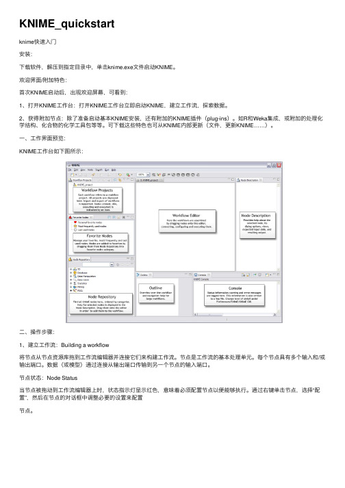
⼀、⼯作界⾯预览:KNIME⼯作台如下图所⽰:⼆、操作步骤:1、建⽴⼯作流:Building a workflow将节点从节点资源库拖到⼯作流编辑器并连接它们来构建⼯作流。
节点是⼯作流的基本处理单元。
每个节点具有多个输⼊和/或输出端⼝。
数据(或模型)通过连接从输出端⼝传输到另⼀个节点的输⼊端⼝。
节点状态:Node Status当节点被拖动到⼯作流编辑器上时,状态指⽰灯显⽰红⾊,意味着必须配置节点以便能够执⾏。
通过右键单击节点,选择“配置”,然后在节点的对话框中调整必要的设置来配置节点。
当通过按下“确定”按钮关闭对话框时,将配置节点,并且状态指⽰灯变为黄⾊:节点已准备好执⾏。
右键单击节点,再次显⽰启⽤的“执⾏”选项; 按下它将执⾏该节点,并且该节点的结果将在输出端⼝可⽤。
成功执⾏后,节点的稳态灯为绿⾊。
可通过浏览输出端视图来检查结果:在上下⽂菜单中的最后⼀个条⽬打开它们。
端⼝左侧的端⼝是输⼊端⼝,提供来⾃前续节点的输出端⼝的数据。
右边的端⼝是输出端⼝。
节点对数据的操作结果在输出端⼝提供给后续节点。
⼯具提⽰提供了有关节点输出的信息,更多信息可以在节点描述中找到。
节点被键⼊,使得仅可以连接相同类型的端⼝。
数据端⼝:最常见类型是从节点到节点传输平⾯数据表的数据端⼝(⽩⾊三⾓形)。
数据库端⼝:在数据库中执⾏命令的节点可以由其数据库端⼝识别(棕⾊⽅块):PMML端⼝:通过蓝⾊平⽅PMML端⼝,数据挖掘节点学习传递到参考预测器节点的模型。
memoQ_QuickStartGuide_6_2_中文快速上手指南

集成翻译环境快速入门指南© 2004-2013Kilgray Translation Technologies.版权所有译者:许欣蕾 审校:李雨北京大学语言信息工程系2012级学生目录 (2)介绍 (4)1.1 翻译环境 (4)1.2 生产率 (5)2 安装及系统要求 (6)2.1 改变用户界面语言 (6)3 翻译过程 (7)3.1 项目 (7)3.2 使用 memoQ 进行翻译 (7)3.3 使用 memoQ 工作 (8)4 创建和修改项目 (9)4.1 创建项目 (9)4.1.1 修改当前项目 (12)4.2 创建翻译记忆库 (12)4.3 创建术语库 (12)4.4 添加更多资源 (13)5 翻译和翻译窗格 (14)5.1 打开文档进行翻译 (14)5.2 编辑翻译 (14)5.3 确认句段 (15)5.4 合并及分割句段 (15)5.5 使用翻译结果 (15)如果没有自动建议:在翻译记忆库和术语库中查找信息 (17)5.7 创建您自己的术语库 (19)5.8 Pre-translation(预翻译) (20)5.9 过滤和筛选 (20)5.10 句段状态 (20)5.11 使用格式标签 (20)5.12 使用预测输入 (22)5.13 使用AutoPick(自动选取) (23)6 交付翻译 (24)6.1 以原始格式交付文档 (24)6.2 以双语文件格式交付文档 (24)6.3 交付翻译记忆库 (25)7 处理分发包任务 (26)7.1 从分发包中创建项目 (26)7.2 交付译文 (26)8 处理在线项目 (28)8.1 开始工作:查看在线项目 (28)8.2 处理在线项目 (30)8.3 交付任务 (31)9 常用键盘快捷键 (32)本指南包含memoQ6.2和translator pro两个版本。
内容包括本软件英文用户界面的信息。
目前我们还在不断地完善这些文字信息。
如有变更,恕不提前通知。
memoQ_QuickStartGuide_6_2_中文快速上手指南
集成翻译环境快速入门指南© 2004-2013Kilgray Translation Technologies.版权所有译者:许欣蕾 审校:李雨北京大学语言信息工程系2012级学生目录 (2)介绍 (4)1.1 翻译环境 (4)1.2 生产率 (5)2 安装及系统要求 (6)2.1 改变用户界面语言 (6)3 翻译过程 (7)3.1 项目 (7)3.2 使用 memoQ 进行翻译 (7)3.3 使用 memoQ 工作 (8)4 创建和修改项目 (9)4.1 创建项目 (9)4.1.1 修改当前项目 (12)4.2 创建翻译记忆库 (12)4.3 创建术语库 (12)4.4 添加更多资源 (13)5 翻译和翻译窗格 (14)5.1 打开文档进行翻译 (14)5.2 编辑翻译 (14)5.3 确认句段 (15)5.4 合并及分割句段 (15)5.5 使用翻译结果 (15)如果没有自动建议:在翻译记忆库和术语库中查找信息 (17)5.7 创建您自己的术语库 (19)5.8 Pre-translation(预翻译) (20)5.9 过滤和筛选 (20)5.10 句段状态 (20)5.11 使用格式标签 (20)5.12 使用预测输入 (22)5.13 使用AutoPick(自动选取) (23)6 交付翻译 (24)6.1 以原始格式交付文档 (24)6.2 以双语文件格式交付文档 (24)6.3 交付翻译记忆库 (25)7 处理分发包任务 (26)7.1 从分发包中创建项目 (26)7.2 交付译文 (26)8 处理在线项目 (28)8.1 开始工作:查看在线项目 (28)8.2 处理在线项目 (30)8.3 交付任务 (31)9 常用键盘快捷键 (32)本指南包含memoQ6.2和translator pro两个版本。
内容包括本软件英文用户界面的信息。
目前我们还在不断地完善这些文字信息。
如有变更,恕不提前通知。
Quick Setup - 项目器快速安装指南说明书

Quick SetupIMPORTANT: Before using the projector, make sure you read these instructions and the safety instructions in the online User’s Guide .Note: Your product may differ from the illustrations on this sheet, but the instructions are the same.Connect the projectorComputerChoose from the following connections. See the sections below or the online User’s Guide for details.HDMI portConnect one end of an HDMI cable to one of the projector’s HDMI ports andthe other end to an HDMI port on your computer.Computer portComputer ports, and the other end to your computer’s monitor port. If you are using a laptop, audio cable.USB portConnect the square end of a USB cable to the projector’s USB-B (square) port. Connect the flat end of the cable to any USB port on your computer.Windows ® 7 or later: After turning on the projector, follow the on-screen instructions to install the Epson ® USB Display software (EMP_UDSE.EXE ; only on first connection). If the software screen does not display automatically, open My Computer , Computer , or This PC , then double-click EPSON_PJ_UD .OS X 10.8.x or higher: After turning on the projector, the setup folder for USB Display appears in the Finder. Double-click USB Display Installer and follow the on-screen instructions to install the Epson USB Display software(only on first connection). If the software screen does not display automatically, double-click EPSON_PJ_UD , then double-click USB Display Installer .External monitor and speakersYou can connect an external monitor and external speakers to your projector to enhance your presentations. See the online User’s Guide for details.Wired networkConnect the projector to your network using an Ethernet cable. See “Wirednetwork configuration” on the back of this sheet for more information.MicrophoneConnect a dynamic microphone to the Micport, using a 3.5 mm mini-jack cable.Video deviceConnect multiple video devices and use the Source Search button on theprojector or remote control to switch between them. For more information on playing sound through the projector, see the online User’s Guide .Component video to VGA cableAudio cableRCA video cable (composite video)HDMI cableCamera, USB device, or document cameraConnect a digital camera, USB flash drive, USB storage device, or Epson DC-06or DC-07 document camera to the projector’s USB-A (flat) port.If you connect a digital camera, USB flash drive, or USB storage device, you can use the projector’s PC Free feature. See the online User’s Guidefor details.Using the remote controlInstall the two AA batteries as shown.Choose which sourceto displayand offAccess projector menusdisplay and sound Access the HomescreenNavigate projectormenusControl projectorvolumeFor more information on using the remote control, see the online User’s Guide.Turn on your equipment1 Turn on your computer or video source.2 M ake sure the power cord is connected and plugged into an3 P ress the power button on the projector or remote control. Theprojector beeps, and the Status light flashes blue and then stays on.Note: To shut down the projector, press the power button twice.4 I f you don’t see an image, press the Source Search button on theremote control to select the image source.N ote: If you still see a blank screen or have other display problems, seethe troubleshooting tips on the back of this sheet.5 U se the arrow buttons on the remote control to highlight any of theoptions on the Home screen, then press to select it.6 T he default language of the menu system is English. To select anotherlanguage, press the Menu button on the remote control. SelectManagement and press . Select Language and press . Select yourlanguage and press . Press the Menu button to exit the menu system.Adjust the image1 T o raise the image, press the foot release button and lift the front of theprojector. Release the button to lock the foot in position.correct the image shape.5 or ,Wireless networkconfigurationF ollow these steps to set up the projector for a wireless network connection.1 Press the Menu button on the remote control.2 Select the Management menu and press .3 Select On as the Wireless LAN Power setting.4 Select the Network menu and press .5 Select Network Settings and press .6 Select Wireless LAN as the Priority Control Interface setting.7Select one of the following as the Simple AP setting:•O n for a direct connection to a computer, tablet, or smartphone.•O ff to connect your projector to a router or access point. N ote: If you directly connect to the projector, you can only project locally stored content.8 Select any other wireless settings as necessary. See the online User’s Guide for details.9When you are finished, return to the Network Settings menu and select Set to apply your settings.Wired network configurationFollow these steps to set up your projector for a wired network connection.1 P ress the Menu button on the remote control, select the Network menu,then press.2 Choose Network Settings and press .3 Select Wired LAN as the Priority Control Interface setting.4Select the Wired LAN menu and press.5 Choose IP Settings and press.6If your network assigns addresses automatically, make sure the DHCP setting is on. If not, make sure DHCP is off and enter the projector’s IP Address , Subnet Mask , and Gateway Address , as needed. Then press Esc .7 To prevent the IP address from appearing on the network standby screen, set the IP Address Display setting to Off .8 When you are finished, return to the Network Settings menu and select Set to apply your settings.9Press the Menu button to exit the menu system.Install the optional softwareDownload the Epson iProjection™ software and manual from your product’s support page (see “Where to get help”) and install the program on each computer that will project over the network.To monitor and control your projector over the network, download andinstall the Epson Projector Management software (Windows only) and manualfrom your product’s support page (see “Where to get help”).Project over a networkIf you need to configure the projector for a wired network, see “Wired network configuration”.1Press the LANbutton on the remote control. You see this screen:2Start Epson iProjection on your computer.Windows 10: Select > EPSON Projector > Epson iProjectionVer X.XX .Windows 8.x: Navigate to the Apps screen and select Epson iProjection Ver. X.XX .W indows 7: Select or Start > Programs or All Programs > EPSON Projector > Epson iProjection > Epson iProjection Ver X.XX . macOS: Double-click the Epson iProjection icon in the Applications folder.3Select Advanced Connection Mode and click OK.4Select the projector you want to connect to, then click Join .If you don’t see the projector you want, click the Automatic search button to find the projector automatically, click the Manual search button to enter the projector’s IP address, or click the Profile button to find the projector based on a previously saved profile.5If you see a message asking for a keyword, enter the four digits that appear on the LAN standby screen and click OK .Your computer image is projected, with a floating toolbar:When you’re done presenting, click Disconnect All on the toolbar.Using the Epson iProjection appYou can project wirelessly from a mobile device (iOS, Android™, or Chromebook™) using the Epson iProjection app and a QR code.1Use the following QR code to download and install the EpsoniProjection app.2 If you connected the projector to a network wirelessly, make sure to connect your mobile device to the same network.3P ress the LAN button on the remote control to display a QR code on the projector screen.4 Start Epson iProjection on your mobile device.5Use the QR code reader feature to read the QR code displayed.6Follow the app instructions to connect your device to the projector.For more information on setting up and using this app, visit/projectorapp (U.S.) or www.epson.ca/projectorapp (Canada) or /iprojection (Caribbean).Using web remoteYou can use a standard web browser to control the projector through the network. A virtual remote control on your computer screen lets you perform many of the same functions as you can with the physical remote control.1Open your web browser and enter the IP address of the projector you want to monitor in the browser’s address bar.If you’re not sure what the IP address of the projector is, turn the projector on and select Wired LAN Info or Wireless LAN Info from the Network menu to display the IP address of the projector. (Do not enter the leading zeroes.)2 Enter EPSONWEB as the default user name and admin as the default password, then click OK . The Epson Web Control menu opens.3 Select Basic Control . If you see a login screen, enter EPSONREMOTE as the user name and guest as the password.4Use the on-screen buttons to operate the projector, as you would using the remote control. See the online User’s Guidefor details.Turn off pictureand soundSelect equipment connected to an HDMI portSelect equipment connected to the USB-A portSelect wired or wireless network signalSelect video signal Select USB display signalTroubleshootingIf you see a blank screen or the No signal message after turning on your computer or video device, check the following:•Make sure the Status light on the projector is blue and not flashing. • P ress the Source Search button on the projector or the remote control to switch to the correct image source, if necessary.•Press the Home button on the projector or remote control to verify the source input and settings.• O n Windows 7 or later, hold down the Windows key and press P at the same time, then click Duplicate .• If you’re using a Windows laptop, press the function key on your keyboard that lets you display on an external monitor. It may be labeled CRT/LCD or have an icon such as . You may have to hold down the Fn key while pressing it (such as Fn + F7). Wait a moment for the display to appear.•I f you’re using a Mac laptop, open System Preferences and select Displays . Click the Arrangement tab and select the Mirror Displayscheck box.EPSON and PowerLite are registered trademarks, Epson iProjection is a trademark, and EPSON Exceed Your Vision is a registered logomark of Seiko Epson Corporation.PrivateLine is a registered trademark of Epson America, Inc.Mac, macOS, and OS X are trademarks of Apple Inc., registered in the U.S. and other countries.Windows is a registered trademark of Microsoft Corporation in the United States and/or other countries.Android and Chromebook are trademarks of Google LLC.General Notice: Other product names used herein are for identification purposes only and may be trademarks of their respective owners. Epson disclaims any and all rights in those marks.This information is subject to change without notice. © 2020 Epson America, Inc., 6/20 CPD-59293RegistrationRegister today to get product updates and exclusive offers. You can register online at /webreg .Where to get helpManualsFor more information about using the projector, see the online manuals. You can view or download the manuals from the Epson website, as described below.Internet support servicesVisit /support (U.S.) or www.epson.ca/support (Canada) and search for your product to download software and utilities, view manuals, get FAQs and troubleshooting advice, or contact Epson.Telephone supportTo use the Epson PrivateLine ® Support service, call (800) 637-7661. This service is available for the duration of your warranty period. You may also speak with a support specialist by calling (562) 276-4394 (U.S.) or (905) 709-3839 (Canada).Support hours are 6 am to 8 pm , Pacific Time, Monday through Friday, and 7 am to 4 pm , Pacific Time, Saturday. Days and hours of support are subject to change without notice. Toll or long distance charges may apply.Optional accessoriesFor a list of optional accessories, see the online User’s Guide .You can purchase screens, optional mounts, or other accessories from an Epson authorized reseller. To find the nearest reseller, call 800-GO-EPSON (800-463-7766). Or you can purchase online at (U.S. sales) or www.epsonstore.ca (Canadian sales).。
DEIF丹控AGC 200 控制器快速入门手册

AGC 200发电机组控制器●供货内容●使用准备●起始步骤●使用AGC 200AGC 200 quick start guide 4189340861 CN1. 总则1.1. 警告、法律信息和安全须知 (3)1.1.1. 警告和注意 (3)1.1.2. 法律信息和免责声明 (3)1.1.3. 安全事项 (3)1.1.4. 静电释放注意事项 (3)1.1.5. 出厂设置 (3)1.2. 关于快速入门手册 (3)1.2.1. 总目的 (3)1.2.2. 目的用户 (4)1.2.3. 内容和整体结构 (4)2. 供货内容2.1. 标准供货范围 (5)2.1.1. 标准供货范围 (5)2.2. 用户可选择的发货 (6)3. 使用准备3.1. 首次通电 (8)3.1.1. AGC 200单机应用 (9)3.1.2. AGC 200孤岛 (10)3.1.3. AGC 200主电网 (11)3.1.4. AGC 200母联开关 (12)3.2. DEIF应用软件(USW)使用准备 (13)3.2.1. 下载软件 (13)3.2.2. USB驱动程序的安装 (13)3.2.3. 准备连接 (13)3.2.4. 从装置中读取参数 (16)3.2.5. 使用服务软件进行基本配置 (16)4. 显示器按钮和LED4.1. 按钮功能 (18)4.2. LED功能 (19)4.2.1. 显示面板导航 (20)4.3. 控制器设定 (20)4.3.1. 可用控制器 (20)4.3.2. 控制器输出类型 (20)1. 总则1.1 警告、法律信息和安全须知1.1.1 警告和注意此文档将会出现大量的帮助用户使用的警告和注意符号。
为了确保用户可以看到这些信息,它们将以与正文相区别的方式被显示出来。
警告警告表示如不按照提示操作,将会存在人员伤亡或设备故障的潜在危险。
注意注意符号提供给用户的是非常有用需要熟记的信息。
1.1.2 法律信息和免责声明DEIF对发电机组的安装和操作不负任何责任。
Interface BX8 测量系统快速入门指南说明书

BX8 Quickstart Guide IntroductionModel BX8 is the newest addition to Interface’s family of measurement systems. Easy enough for the inexperienced user but powerful enough for the sophisticated test engineer, with the BX8 anyone can be up and measuring in minutes. Designed specifically for use with mV/V output sensors such as force, torque and pressure along with PT1000 thermocouples, and ±10V output sensors, the BX8 puts graphing, logging and display capabilities at a user’s fingertips. The BX8 also includes 1/4 and 1/2 bridge completion for seamless integration of strain gage measurements. Eight independent, user configurable, 16-bit scalable analog outputs can be connected to external devices.Caution: Please read this entire guide before making any connections or powering the BX8. Software and Drivers MUST be installed first. Refer to the Installation Diagram for the correct BX8 model.BX8-AS Installation (Terminal or M16 Input)F IGURE 1–6A XIS L OAD C ELL TO BX8-AS T ERMINAL B LOCK I NPUTF IGURE 2-6L OAD C ELLS TO BX8-AS T ERMINAL **NOTE – Refer to the Operating Manual for Sense Lines**F IGURE 3-6A XIS L OAD C ELL TO BX-AS M16C ONNECTOR I NPUTF IGURE 4-6S EPARATE L OAD C ELLS TO M16 CONNECTORF IGURE 5-D IAGRAM OF BX8-ASBX8-HD44 InstallationF IGURE 6-6A XIS L OAD C ELL TO BX8-HD44I NPUTF IGURE 7-6L OAD C ELLS TO BX D-HD44I NPUT**NOTE – Refer to the Operating Manual for Sense Lines**F IGURE 8–BX8-HD44D IAGRAMBX8-HD15 InstallationF IGURE 9-6A XIS L OAD C ELL TO BX8-HD15F IGURE 10–8S EPARATE L OAD CELLS TO BX8HD15**NOTE – Refer to the Operating Manual for Sense Lines**F IGURE 11-BX8-HD15D IAGRAMBlueDAQ Software Installation1. Please follow these instructions carefully.DO NOT connect the amplifier to the PC until instructed to do so. TheBlueDAQ PC software is included on a USB Flash Drive with the amplifier or can be downloaded from2. Install the software by double-clicking the “setup.exe” file located in the BlueDAQ folder. You may need to “Extract”the contents of the folder first if you downloaded it from the website. Follow the instructions for installation. Once the software completes installation you MUST restart your computer.3. Attach the amplifier to the PC using the supplied USB A-B cable. BSC4, BSC8 and BX8 drivers were installed with theBlueDAQ software and Windows will automatically load them. BSC8D/BX8 must be powered ON using supplied power cable and power switch. 9330 drivers must be installed as described below.4. When the device is connected in Communication mode for the first time, Windows will ask for a driver directory. Theinstallation process is described below. The driver is located on the USB Flash drive supplied with the 9330. The Flash drive MUST be connected to the PC or the files copied to the PC before connecting the 9330 to the PC.5. Enable USB Communication mode. To do this, click the MODE button of the measuring amplifier and selectUSBmode: Comm in the logger menu.6. Now you can connect your 9330 to the PC via USB cable. Once connected the driver installation window appears.Select “Install software from a list or specific source (advanced users)” and Click “Next >”.F IGURE 12-F OUND N EW H ARDWARE W IZARD7. Click “Search for the best driver in these locations”8. Check the option “Include this location in the search:” and then click “Browse”. Select the folder: 9330_Com_Driverfrom the supplied USB drive and Click “Continue >”.F IGURE 13-N EW H ARDWARE W IZARD9. In the dialogue window “Hardware installation” click “Continue installation”.F IGURE 14-H ARDWARE I NSTALLATION10. The driver was installed successfully. Click “Finish”.F IGURE 15-H ARDWARE I NSTALL F INISHCOM PortsOnce windows is finished installing the device navigate to Device Manager and check for a new USB Serial Port (COMX) where X is the assigned port number. Remember this number. In the examples below it is COM6 or COM28F IGURE 16-E XAMPLE OF BSC4F IGURE 17-E XAMPLE OF 9330COM PORTF IGURE 18-E XAMPLE OF BX8COM PORTF IGURE 19-BSC8D INSTALLS AS A D ATA A CQUISITION D EVICEBlueDAQ – Adding a New Channel1. Adding a New ChannelF IGURE 20-M AIN M ENU2. Under Devicetype, select the device. In this example we are using a BX8.F IGURE 21-A DD C HANNEL M ENU3. Under Communication Interface, select the correct COM port. In this Example our COMport Number is COM9.F IGURE 22-A DD C HANNEL M ENU4. Under Input Channel, select how many channels. In this example we are using a 6 Axis Load Cell, so we will selectLast 6.F IGURE 23-A DD C HANNEL M ENU5. Click ConnectAdding a Sensor with a .Dat File 1. Under the Sensor Option, Click on Multi-axisF IGURE 24-S ENSOR D ROPDOWN M ENU2. If this is a new Sensor, Click on the Remove button to remove the previous sensor.F IGURE 25-S ENSOR M ENU3. Once the Remove button has been clicked, the Channel assignment will reset.F IGURE 26-S ENSOR M ENU,R EMOVE B UTTON4. Click on Add Sensor and Open File / Dir..F IGURE 27-A DD S ENSOR M ENU5. In this Example, the Multi-Axis SN is 15485857, so 15485857.dat will be selected.F IGURE 28-S ELECTING THE C ORRECT D ATA F ILE6. Click OK after selection.F IGURE 29-S ENSOR DATA SELECTED7. Verify the Sensor Serial is correct.F IGURE 30-A DD S ENSOR M ENU -F ILE SELECTED8. Click Auto-Rename Channels to properly assign channels.9. The default Channels will change from Chan X_X to ForceX or Torque, depending on the .dat file used.F IGURE 31-A UTO-R ENAME C HANNELS C LICKED10. Click OK Enable this sensor11. Select Overwrite existing and OK.F IGURE 32-O VERWRITE12. Enter password (if required), enter the correct pass and click OK.F IGURE 33–P ASSWORD R EQUIREDAdding a Single Channel - Without a .Dat File1. Run BlueDAQ from the start menu. After the program launches click “ADD CHANNEL”F IGURE 34-A DD C HANNEL2. In the Add Channel dialog box2.1. Click Devicetype drop-down and select BSC4, BSC8, BX8, or BSC2 (9330)3. Click the Device dropdown box and select the device, select the COM Port (See Device Manager if unknown) andopen the correct amount of input channels (First = 1 and Last = total # of channels for device). For Model 9330, you will not be allowed to change the number of channels. Example, if using 3 load cells then Last will be 3.4. Click ConnectF IGURE 35-A DD C HANNEL M ENU5. BSC8 has a slightly different add channel box. Select Dev1 instead of Com port. Please remember to open theneeded amount of input channels.F IGURE 36-E XAMPLE BSC8D EVICE6. Each channel must now be scaled using the “SCALING” dialog box. Each channel must be scaled independently. Ifthe BSC8 was purchased with Interface load cells and a System Setup and Scaling then the scaling values will be taken from the “Load Cell / BSC8 Digital Bridge Amplifier Calibration Certificate”F IGURE 37-E XAMPLE OF S CALING6.1. Physical full scale is typically the capacity of the sensor.6.2. Electrical full scale output is the output of the sensor at the Physical full scale.6.3. Input Range is always 2 mV/V and should not be changed.F IGURE 38-S CALING USING C ALIBRATION C ERTIFICATE6 Example scaling a channel using model WMC-100 load cell with 100 lbf capacity and 1.9587 mV/V output. Afterentering the values into the dialog box you must click “Calculate” and then “OK/Set”.F IGURE 39-E XAMPLE OF C ALIBRATION FOR A WMC-100L OAD C ELL7 Once each channel has been scaled the software is ready to take measurements.Measurement and Recording1. Click Set All Zero before measuringF IGURE 40-Z ERO V ALUES2. Click YESF IGURE 41–P ROCEED WITH Z ERO R ESET3. Click OK to Start MeasuringF IGURE 42-S UCCESSFUL Z ERO4. Click Start MeasuringF IGURE 43-M EASUREMENT5. Recording Options are available.F IGURE 44-M EASUREMENT I NITIATED6. Recorder Tab, measurements of all Axis.F IGURE 45-V ALUES M EASURED7. Value Display shows values in each Axis.F IGURE 46-V ALUE DISPLAY S CREENWarrantyAll Telemetry products from Interface Inc., ('Interface') are warranted against defective material and workmanship for a period of (1) one year from the date of dispatch. If the 'Interface' product you purchase appears to have a defect in material or workmanship or fails during normal use within the period, please contact your Distributor, who will assist you in resolving the problem. If it is necessary to return the product to 'Interface' please include a note stating name, company, address, phone number and a detailed description of the problem. Also, please indicate if it is a warranty repair. The sender is responsible for shipping charges, freight insurance and proper packaging to prevent breakage in transit. 'Interface' warranty does not apply to defects resulting from action of the buyer such as mishandling, improper interfacing, operation outside of design limits, improper repair or unauthorized modification. No other warranties are expressed or implied. 'Interface' specifically disclaims any implied warranties of merchantability or fitness for a specific purpose. The remedies outlined above are the buyer’s only remedies. 'Interface' will not be liable for direct, indirect, special, incidental or consequential damages whether based on the contract, tort or other legal theory. Any corrective maintenance required after the warranty period should be performed by 'Interface' approved personnel only.Revision HistoryAuthor Revision Release DateKB E 02/22/2018PB F 01/16/2019。
Empower 3_3 QuickStart数据采集_Hclass_2017
FLR检测器
-2D模式(2D Mode)
PMT Gain
FLR检测器
-模拟输出(Analog Out)
FLR检测器
-事件(Events)
Run Events
FLR检测器
-3D模式(3D Mode)
FLR检测器
-光谱λ-λ模式(Spectrum λ-λ Mode)
ELSD检测器
-通用(General)
5.0 5.1 9.0
流动相A(%) 流动相B(%)
70
30
10
90
70
30
70
30
对于一个梯度方法,建议第一行先做“平衡”(梯度第一行的比例运 行);再做一个“平衡色谱柱 ”,在不进样的条件下运行整个梯度方 法,对色谱柱进行平衡。
样品队列调整
样品队列调整
Hide Column
选中某一列,点击右键,可以对其隐藏
用选择的仪器方法监测(Monitor)基线
概览
运行样品界面 仪器方法和方法组
— 创建仪器方法 — 创建方法组
运行样品
— 监视基线 — 如何进样检测单个样品 — 创建样品组方法 —-仪器
点击“新建方法” New Method
Instrument
单针进样(Single Injection)
点击“单进样”
单针进样(Single Injection)
Sample name function: 选择进样类型
Method set vial
Injection volume Run Time
Options
Develop Method Set
Inject
80 60 40 20
0 0
Univention企业服务器快速入门指南说明书

Quick start guide for UniventionCorporate ServerRelease5.0Oct24,2023 Contents1Introduction1 2Installation2 3UCS web interface3 4UCS updates/Installing additional software5 5Configuration management using Univention Configuration Registry5 6Clients6 7Further expansion of the domain6 8Further information71IntroductionUnivention Corporate Server(UCS)is a server operating system based on Debian GNU/Linux with integrated man-agement system for the central administration of servers,services,clients,desktops and users.This quickstart guide offers a short introduction on how to get started with UCS.Several features of UCS are only mentioned briefly with a reference to further documentation.The documentation on UCS is available at https://docs. software-univention.de/.The installation DVD can be downloaded from the Univention website at https:///downloads/ download-ucs.The installation DVD is only available for the host architecture amd64(64-bit).It has support for the Unified Extensible Firmware Interface-Standard(UEFI)including SecureBoot.Alternatively preinstalled images for VMware and VirtualBox can be used from the same download page.The system requirements vary considerably depending on the intended purpose and the number of users.The mini-mum requirements for the installation are1GB memory and8GB hard drive space.2InstallationThe installation is performed via a menu-driven installer and can be used both interactively and completely profile-based,see the Extended installation documentation1.The system language,keyboard layout and time zone can be selected in accordance with local requirements.A valid network configuration should be set during the installation.If,for example,a gateway and a name server are specified,but the name server cannot be reached,this may result in unnecessary timeouts.In these cases,it makes more sense not to specify a gateway.The network configuration can be employed using DHCP.If there is already a name server available in the local network,it should be used.If additional UCS systems are installed in the domain at a later point in time,the Primary Directory Node and any Backup Directory Node systems should be entered as name servers.Fig.2.1:Selecting the domain setupDuring installation,the system can be used for various purposes which can only be configured at this point in the setup process.•The system is to be the first system in a new UCS domain and it is implicitly configured with the system role Primary Directory Node.•The system can be joined into an existing Active Directory domain.Select this option if UCS should not createa new domain.UCS then takes on the role of an Active Directory member server.1https://docs.software-univention.de/ext-installation/5.0/en/index.html•All other systems are joining the UCS domain when they are installed.An overview of the other different system roles can be found in UCS Manual-System roles2.With UCS and the Active Directory Takeover app an existing Active Directory domain can be migrated completely to UCS.For information on how to set up the UCS system for this scenario,see UCS Manual-Migrating an Active Directory domain to UCS using Univention AD Takeover3.In the subsequent course of the installation,the fully qualified host name,under which the computer should be accessible in the network,is entered for a Primary Directory Node.A local name should also be used as the domain name in this case,pany.intranet.(If the system is used as a mail server,for example,the mail domains can be used independently of the domain names).For example,to commission the mailserver host system in the company.intranet DNS domain,pany.intranet should be entered as the fully qualified host name.The LDAP base is suggested based on the fully qualified host name and only needs to be adjusted in exceptional cases.For all other systems roles it is normally sufficient to enter the host name only.The domain name will we fetched from the Primary Directory Node when the domain is joined.The root password must be at least eight characters long and is also set as the password for the user Administrator during the installation of the first UCS system(Primary Directory Node).An auto-partitioning feature can be used during the installation which creates an LVM volume group on the first hard drive by default.The installed software components can be adapted later at any time and subsequently installed from the Univention App Center.After confirming the configuration settings the installation is initiated.Once completed,the system must be restarted. The further configuration is made using the Univention Management Console(UMC).This is described in more detail in the following chapter.3UCS web interfaceThe web interface of an installed UCS system is directly available via its IP address(https://server_ip or http://server_ip,HTTPS is recommended).By default,a portal page is configured on the Primary Directory Node where all applications are listed that are installed in the domain.For all other system roles,the start site consists of an overview of all locally installed applications.(View as well as the partitioning of entries can be customized in a very flexible manner,see also UCS manual-Portal page as central view on the UCS domain4.)On each start site of a UCS system,there is an entry System and domain settings in the section Administration(or System settings,respectively)that points to the Univention Management Console(UMC)of the local system.Uni-vention Management Console is the central tool for web-based administration of a UCS domain.There are different modules available on the UCS system depending on the installation and system role selected.The login to Univention Management Console is performed as user Administrator with the password specified for the user root during the installation.For administrating UCS,the LDAP directory is the central component of a UCS domain.In the LDAP,domain wide information such as the users,groups and computer accounts is saved.Depending on the settings,this information is replicated to the other Directory Nodes in the domain either completely or selectively.The UMC modules which edit the LDAP directory directly can be accessed only on the Primary Directory Node via Univention Management Console.Furthermore,they can also be controlled using the command line interface Univention Directory Manager, see UCS manual-Command line interface of domain management(Univention Directory Manager)5.2https://docs.software-univention.de/manual/5.0/en/domain-ldap/system-roles.html#system-roles3https://docs.software-univention.de/manual/5.0/en/windows/ad-takeover.html#windows-ad-takeover4https://docs.software-univention.de/manual/5.0/en/central-management-umc/portal.html#central-portal5https://docs.software-univention.de/manual/5.0/en/central-management-umc/udm-command.html#central-udmFig.3.1:Illustration of the portal page on the Primary Directory Node with all domain wide available applicationsFig.3.2:Modules in the UMC4UCS updates/Installing additional softwareUCS updates can be installed in the UMC module Software update.Additional software,like for example the Active Directory Connection,can be installed using the Univention App Center in the Univention Management Console:•Additional UCS software can be installed/removed using the category UCS components.•Third-party software(e.g.various groupware solutions)and UCS-compatible add-on products(e.g.UCS@school for school deployment can also be installed through the App Center.Fig.4.1:Subsequent installation of UCS components5Configuration management using Univention Configuration RegistryUnivention Configuration Registry is the central tool for managing the local system configuration of a UCS system. Settings are specified in a consistent format,the so-called Univention Configuration Registry variables.These vari-ables are used to generate the configuration files used effectively by the services/programs.Direct editing of the configuration files is only needed in exceptional cases.Univention Configuration Registry variables are managed via the Univention Management Console module Univention Configuration Registry.Configuration files are automatically updated when the UCR variables registered on them are changed.Fig.5.1:Managing Univention Configuration Registry variables6ClientsIn addition to the UCS systems,a UCS domain can also integrate different clients.The following clients are supported:•Microsoft Windows clients can join an AD-compatible Windows domain provided by the Active Directory compatible domain controller component(implemented using the software Samba).Further information on setting up Samba and the domain join of Windows clients can be found in UCS Manual-Windows domain joins6.•macOS systems are also integrated via a Samba-based,AD-compatible Windows domain.Further information on setting up Samba and the domain join can be found in UCS Manual-Mac OS X domain joins7.•Ubuntu systems(see Integration of Ubuntu clients into a UCS domain8)and other Linux distributions like Debian,SUSE or Red Hat can also be integrated into the domain,see Integration of Linux/Unix systems intoa UCS domain9.7Further expansion of the domainThis quickstart guide only provides an entry into UCS.UCS is very scalable,additional services can simply be installed on additional systems.This domain join is described in UCS Manual-How UCS systems join domains10.UCS offers various additional services which are covered by the UCS license and which can be integrated at a later point in time:•Single-sign-on with web services using a SAML identity provider,see UCS manual-SAML identity provider11.6https://docs.software-univention.de/manual/5.0/en/domain-ldap/domain-join.html#windows-domain-join7https://docs.software-univention.de/manual/5.0/en/domain-ldap/domain-join.html#macos-domain-join8https://docs.software-univention.de/ext-domain/5.0/en/ubuntu.html#ext-dom-ubuntu9https://docs.software-univention.de/ext-domain/5.0/en/unix.html#ext-dom-unix10https://docs.software-univention.de/manual/5.0/en/domain-ldap/domain-join.html#linux-domain-join11https://docs.software-univention.de/manual/5.0/en/domain-ldap/saml.html#domain-saml•UCS manual-IP assignment via DHCP12.•UCS manual-Web proxy for caching and policy management/virus scan13.•Hybrid cloud setups8Further informationUnivention Corporate Server provides comprehensive documentation:•The primary source of information on UCS is the UCS Manual for users and administrators14.•Further documentation for advanced scenarios can be found in the extended documentation.The variousdocuments are linked at https://docs.software-univention.de/.•Answers to frequently asked questions can be found in the support and knowledge database(SDB)15.•Questions on UCS can be asked at Univention Help16.12https://docs.software-univention.de/manual/5.0/en/ip-config/dhcp.html#module-dhcp-dhcp13https://docs.software-univention.de/manual/5.0/en/ip-config/web-proxy.html#ip-config-web-proxy-for-caching-and-policy-management-virus-scan 14https://docs.software-univention.de/manual/5.0/en/index.html15https:///c/knowledge-base/supported/4816https:///。
WebInspect_QuickStart快速启动

WebInspect 10.1 QuickStart GuideSystem RequirementsBefore installing WebInspect, make sure that your system conforms to the following list of supportedcomponents. Note that Beta versions of operating systems, service packs, and required third-partycomponents (such as Microsoft SQL Server Express) are not supported.Operating System•Windows 7 (32-/64-bit) with SP1 (Recommended)•Windows XP Professional (32-bit) with SP3•Windows Server 2008 R2 (64-bit) with SP1 (Recommended)•Windows Server 2003 Standard (32-bit) with SP2Notes about Windows 7 Installations•Disable User Account Control (UAC).•Disable themes (recommended).•When installing, make sure that you run as Administrator.•On occasion SQL Compact Edition, a prerequisite for SmartUpdate of SecureBase Checks, will not correctly register into the Global Assembly Cache (GAC) on 64-bit platforms. To ensure thatregistration occurs correctly, consider installing SQL Compact Edition 64-bit version prior to installingWebInspect.Processor• 2.5 GHz Multi-Core (Recommended)• 1.5 GHz Single-Core (Minimum)RAM• 4 GB (Recommended)• 2 GB (Minimum)•100+ GB (Recommended)•10 GB (Minimum)Display•1280 x 1024 (Recommended)•1024 x 768 (Minimum)Database•Microsoft SQL Server 2008 R2 with SP2 (No scan database limit) (Recommended)•Microsoft SQL Server 2008 with SP3 (No scan database limit)•Microsoft SQL Server 2005 with SP4 (No scan database limit)•Microsoft SQL Server 2008 R2 Express with SP2 (10 GB scan database limit)•Microsoft SQL Server 2008 Express with SP3 (4 GB scan database limit)•Microsoft SQL Server 2005 Express with SP4 (4 GB scan database limit) (Minimum) Notes about SQL Server•When using a version of SQL Server Express, scan data must not exceed the limit on database size for that version, as stated above. For larger scans, or to permit sharing of scan data, use SQL Server (fullversion).•For SQL Server Express, accept all defaults during installation. WebInspect expects the default instance name “SQLEXPRESS.” The user may also wish to enable the options to “Hide advanced installationoptions” and “Add current user to database administrators.”•The full version of SQL Server 2005 or 2008 can be installed on the local host or collocated nearby.This option can be configured within the WebInspect Application Settings:Edit→Application Settings→Database.Platform•Microsoft .NET Framework 4.0Browser•Internet Explorer:—v9 (Recommended)—v8.0—v7.0 (Minimum)•Mozilla Firefox 19 (Optional)•HP Assessment Management Platform (AMP) v9.x•HP WebInspect Enterprise v9.30•HP Quality Center (QC):—v9.2—v10.0•HP Application Lifecycle Management (ALM) v11.0•HP SecurityScope:—v3.6—v.3.7—v3.8 (required for SecurityScope .Net)•HP Software Security Center:—v3.6 (for WebInspect Enterprise v9.30 and AMP v9.x)—v3.7 (for WebInspect Enterprise v9.30 and AMP v9.x)—v3.8•HP Unified Functional Testing 11.5•IBM Rational ClearQuest v7.1Portable Document Format (PDF)•Adobe Acrobat v11 (Recommended)•Adobe Acrobat v8.1.2 (Minimum)Network•An active Internet connection (for updates)InstallationUse the following procedure to install WebInspect.1Start the installation program.The Welcome to the HP WebInspect 10.1 Setup Wizard window appears.2Click Next.The End-User License Agreement window appears.3Review the license agreement. If you accept it, select the check box and click Next; otherwise click Cancel.If you accept the license agreement, the Destination Folder window appears.4In the Destination Folder window, select the folder into which you want to install the software and click Next.The Sensor Configuration window appears.5If you are installing WebInspect as a sensor for the Assessment Management Platform (AMP) or WebInspect Enterprise:a In the Configure WebInspect as a Sensor for this installation (optional) area, select ConfigureWebInspect as a Sensor.b Enter the Enterprise Manager URL, that is, the URL of the AMP manager or WebInspectEnterprise manager.c In the Sensor Authentication group, enter the Windows account credentials for this sensor.6Click Next.The Ready to Install HP WebInspect 10.1 window appears.7Click Install.When the installation process is complete, the Completed the HP WebInspect 10.1 Setup Wizardwindow appears.8Select Launch HP WebInspect 10.1 and click Finish.The Setup Wizard closes and HP WebInspect launches.LicensingThe first time you start WebInspect, the program displays the License Wizard.The License Wizard prompts you to select one of the following options:•Activate Now•Register 15-day trialTrial RegistrationUse the following procedure to begin a free 15-day trial of WebInspect.1On the Welcome to HP Fortify Licensing window, click Register 15 Day Trial.The wizard displays a window prompting you to enter information about you and your company.2Enter the requested information.3If this computer accesses the Internet through a proxy:a Select the Network Proxy option.b Select a setting from the Proxy Profile drop-down list.c Click Edit and complete the Proxy Profile dialog box as necessary.—If you select Use PAC file to load proxy settings from a Proxy Automatic Configuration (PAC) file, you must click Edit and enter the URL of the PAC file in the Configure proxy using PACFile URL field.—If you select Use Explicit Proxy Settings, you must click Edit and configure a proxy by entering the requested information for the Explicitly configure proxy option.d Click Save on the Proxy Profile dialog box.4Click Next.The program attempts to contact HP servers, which will send an email message to you containing a32-character activation token.5Click Finish.6When the email arrives, in the WebInspect menu bar click Edit→Application Settings.7On the Application Settings window, select License from the left pane.8Enter the 32-digit license token, omitting any hyphens that may appear in the string (or copy the token, position your cursor in the first block of the activation token field, and press Ctrl + V to paste the token).9Click OK.Activate NowIf you have received a token in an email message from HP:1On the Welcome to HP Fortify Licensing window, click Activate Now.The wizard displays the Configure WebInspect Licensing window.2In the Licensing Method group, choose one of the following:•Connect directly to HP corporate license server - Licensing is controlled by a Hewlett-Packard server.•Connect to local HP License and Infrastructure Manager - Licensing is controlled by your local server running HP License and Infrastructure Manager (LIM) software. A link is provided on thisinstallation screen to download the HP License and Infrastructure Manager.The LIM allows you to manage concurrent licenses for HP software in a manner that best suits yourorganization’s development and testing environment. For example, your company may have HPWebInspect software installed on 25 machines, but holds a concurrent license that permits amaximum of 10 instances to be active at any one time. Using the LIM, you can allocate anddeallocate those 10 seats in any way you like, without coordinating or negotiating through HP’scentral licensing facility.3Enter the information requested in the User Information group.4Click Next.If you chose Connect to local License and Infrastructure Manager, the License Wizard displays theConcurrent License Activation window. Go to Connect to LIM on page7.If you chose Connect directly to HP corporate license server, the License Wizard displays theNamed License Activation window. Proceed to Connect to HP.Connect to HP1In the Activation Token area, enter the 32-digit license token sent to you by email from HP. Omit any hyphens that may appear in the string (or copy the token, position your cursor in the first block of theActivation Token field, and press Ctrl + V to paste the token).2If the machine you are attempting to license is connected to the Internet, select Online Activation.a The default License Service URL is https://.Change this URL only if directed to do so by HP Support personnel.b If this computer accesses the Internet through a proxy, select the Network Proxy option and select asetting from the Proxy Profile drop-down list. Click Edit and complete the Proxy Profile dialogbox as necessary.—If you select Use PAC file to load proxy settings from a Proxy Automatic Configuration (PAC) file, you must click Edit, enter the URL of the PAC file in the Configure proxy using PACFile URL field, and click Save on the Proxy Profile dialog box.—If you select Use Explicit Proxy Settings, you must click Edit, configure a proxy by entering the requested information for the Explicitly configure proxy option, and click Save on theProxy Profile dialog box.c Skip to step4.3If WebInspect is installed on a computer that is not connected to the Internet, select Offline Activation.You will create a license request file containing information about that computer and then, using aseparate Internet-connected computer, access an HP Web site to transmit the file to an HP server, which will download a license file that you can copy and install on the computer that is not connected to the Internet.a Click the File button next to the License Request File field.b Select a location where the license request file will be saved. The name of the request file isformatted as <ProductName>_LicenseReq.xml.Be sure to save this file on a portable device or at a location that is accessible by a machine that hasaccess to the Internet.See the License Wizard online Help for additional instructions.4Click Next.Information pertaining to your installed license appears in the License Details section.5Click Finish.This completes the licensing procedure.Connect to LIMThe HP License and Infrastructure Manager (LIM) allows your company to manage concurrent licenses for HP software in a manner that best suits your organization’s development and testing environment. Contact your LIM administrator to obtain the information required for completing this procedure.1In the URL field, enter the URL of the License and Infrastructure Manager.2Enter the name of the license pool and its password in the Pool Name and Password fields.3If authorization is required to access the LIM, select Network Authorization and then enter your user name and password.4If this computer accesses the Internet through a proxy:a Select the Network Proxy option.b Select a setting from the Proxy Profile drop-down list.c Click Edit and complete the Proxy Profile dialog box as necessary.—If you select Use PAC file to load proxy settings from a Proxy Automatic Configuration (PAC) file, you must click Edit and enter the URL of the PAC file in the Configure proxy using PACFile URL field.—If you select Use Explicit Proxy Settings, you must click Edit and configure a proxy by entering the requested information for the Explicitly configure proxy option.d Click Save on the Proxy Profile dialog box.5Click Next.6On the Complete on-site License Activation window, select the manner in which you want the License and Infrastructure Manager to handle the license associated with WebInspect.•Connected License - The computer can run the HP product only when the computer is able to contact the LIM. Each time you start the HP software, the LIM allocates a seat from the licensepool to this installation. When you close the software, the seat is released from the computer andallocated back to the pool, allowing another user to consume the license.•Detached License - The computer can run the HP product anywhere, even when disconnected from your corporate intranet (on which the LIM is normally located), but only until the expirationdate you specify. This allows you to take your laptop to a remote site and run the HP software.When you reconnect to the corporate intranet, you can access the Application License settings andreconfigure from Detached to Connected.7Click Next.Information pertaining to your installed license appears in the License Details section.8Click Finish.This completes the licensing procedure.License RevocationIf your WebInspect license expires, or if your facility is managing licenses through the HP License andInfrastructure Manager and the administrator releases your license, you will not be able to conduct orschedule scans.To regain a license if using the HP License and Infrastructure Manager:1In the WebInspect menu bar click Edit→Application Settings.2On the Application Settings window, select License from the left pane.3Verify your license data.4Click OK.If necessary, contact HP Support or your HP License and Infrastructure Manager administrator. Updating WebInspectHP security engineers uncover new vulnerabilities nearly every day. They then develop attack agents tosearch for these malicious threats, then update our corporate database so that you will always be on theleading edge of Web application security.To ensure that you have up-to-date information about the WebInspect catalog of vulnerabilities, you can usethe Smart Update feature of WebInspect to contact the HP knowledgebase server each time you start theapplication. If vulnerability or program updates are available, WebInspect informs you and asks if you wantto install them.For complete information about updating WebInspect, see the section for the Smart Update tool in theHP WebInspect User Guide.Directory StructureThe following table describes the directories created and used by WebInspect, assuming that the main drive is “C” and the user accepts the default directories suggested by the installation program. This information can assist customers and Technical Support in troubleshooting.1%localappdata% represents the location of local application data for your operating system. For example, for Windows 7 (using the default C: drive), %localappdata% is C:\Users\<username >\AppData\Local .WebInspect Directory Structure Purpose PathCommentsInstallation DirectoryC:\Program Files (x86)\HP\HP WebInspectCan be set by the user during installation. SmartUpdate of full WI version will override everything that exists in this directory.<Installation Directory >\ComplianceTemplatesCompliance template directory; can be modified by Smart Update.<Installation Directory >\SamplesContains subdirectories forsample scans, and a login macro and a WSDL file for .C:\ProgramData\HP\HP WebInspectSubdirectories include Policies, Schedule, SecureBase database, Server Analyzer, Settings, and SupportChannel.C:\ProgramData\HP\Licenses\WebInspect Licenses activated on the localmachine.C:\ProgramData\HP\SmartUpdateSmartUpdate directory where new patches are downloaded. Security checks are copied and inserted into the database; other artifacts are copied into installation directory (e.g., Compliance Template).Application Data Directory %localappdata%\HP 1 All data required for WebInspect that are not user-specific. User Data Directory%localappdata%\HP\HP WebInspect 1All data created by the user and not global for the application. Subdirectories includeComplianceTemplates, Exports, Logs, Plugins, Reporting, ScanData, and Tools.。
火鸟帧抓取器快速入门指南说明书

FireBird Frame Grabbers - Installation and UseQUICKSTART GUIDEFIREBIRD FRAME GRABBERS – QUICKSTART GUIDEContentsFIREBIRD FRAME GRABBERS – QUICKSTART GUIDE 2HARDWARE INSTALLATION 3 SOFTWARE INSTALLATION 4 UPDATING THE FIREBIRD FIRMWARE 5 WHERE TO GO NEXT 6 ACTIVECAPTURE - INTRODUCTION 7 ACTIVECAPTURE - IN USE 8 GENTL CAMERA LINK SETUP UTILITY 9 WHAT ELSE IS INSTALLED? 10 SOFTWARE UN-INSTALLATION 11 CONTACT DETAILS 12DisclaimerWhile every precaution has been taken in the preparation of this document, Active Silicon assumes no responsibility for errors or omissions. Active Silicon reserves the right to change the specification of the product described within this document and the document itself at any time without notice and without obligation of Active Silicon to notify any person of such revisions or changes.Copyright NoticeCopyright © 2022 Active Silicon. All rights reserved. This document may notin whole or in part, be reproduced, transmitted, transcribed, stored in any electronic medium or machine readable form, or translated into any language or computer language without the prior written consent of Active Silicon.Trademarks and AcknowledgementsAll trademarks and registered trademarks are the property of their respective owners.Windows is either a registered trademark or trademark of Microsoft Corporation in the United States and/or other countries.GenICam is a trademark of EMVA, CoaXPress is a trademark of JIIA, Camera Link is a trademark of A3.Part InformationPart Number: FBD-MAN-QS.Power off and open up the computer taking the usual anti-static precautions.Please note: The boards are keyed so that they can only be fitted into a slot in which they will work.Do not modify the FireBird board or the motherboard in an attempt to override the keying as this could result in serious damage.For full performance, boards with a part number including ’PE8’ mustbe fitted in a slot that supportsPCI Express at x8 width; similarly those including ‘PE4’ must use aslot supporting x4. Boards with apart number including ’3PE’ mustbe fitted in a slot that supports PCIExpress at Gen 3 speeds; similarlythose including ‘2PE’ must use a slotsupporting Gen 2 speeds. Check yourcomputer documentation for detailsof the PCI Express connectors.CoaXPress Boards Only: Formultichannel CoaXPress boards,and the 1XCXP6-2PE8 board, if theboard will be used to power camerasthrough the CoaXPress cables usingPoCXP then the auxiliary powerconnector J13 must be connectedto the computer power supply. Thecorrect power supply cable is oneintended for PCI Express Graphics(PEG) cards, and may have 6 or 8ways. To distinguish it from othersimilar connectors in the computer,the connector should be black andmay be marked ‘PCI-E’ or ‘PEG’. Similarconnectors that are not PEG should bewhite. However this is often not thecase, so the cables should be carefullychecked for the pattern of squaresand chamfers on the plastic body ofthe connector at the end of the cable.See the images below.Also, the wires should be black onthe side with the connector clip, andcolored (often yellow or blue) on theother side.If the connector does not matchthose shown above, DO NOTattempt to force it into FireBird asthis could result in serious damage.If a 6 way connector is plugged intoFireBird, it should be aligned at theupper 6 ways of the 8 way FireBirdconnector as shown below.PEG cable splitters, PEG to SATAadapters and PEG to ‘Molex’ adaptersare available from Active Silicon andare included in the optional cablestarter kit.Close and power on the computer.The Active Silicon FireBird Package includes the FireBird Driver (device driver and core libraries), various applications including ActiveCapture, a GenICam-based GUI program, and the GenTL Producer. Additionally, ActiveSDK is for software developers.By default, selecting Typical installs everything, but individual options can be deselected if required (see image below). The packages are supplied as a compressed file which includes the installation package along with theseinstructions and the release notes.The file naming convention is:as-<product>-<OS>- vXX_YY_ZZwhere <product> is:z fbd-cxp for the FireBird CoaXPressPackage.z fbd-cl for the FireBird Camera LinkPackage.z fbd-sdk for the FireBird ActiveSDKPackage.Windows® 10 and 11Uninstall any previous version ofthe Active Silicon FireBird Package(see page 11). Note: The previousSDK can be left on the PC to allowdevelopers to refer to both old andnew SDKs.Un-zip the required msi package to alocal disk.Run the msi.Follow the on-screen prompts,including to reboot the PC onceinstallation has completed.After completing installation it isrecommended to update the FireBirdfirmware (see the next page).Windows ServicePart of the installation is a Windowsservice ‘Active Silicon FireBird’ whichautomatically runs as Windows starts.This loads the main firmware intoFireBird boards with part numbersincluding ‘3PE’. Until the service runsthese boards have limited functionality,and from a hardware viewpoint theydo not power or discover connectedcameras and LEDs do not function. Thisprocess is needed to meet PCI Expressrequirements with the larger FPGA used.Other Operating SystemsSee the specific Quickstart Guidesupplied with the installation package.It is recommended to always update the firmware on FireBird boards to match that in the current driver set. This is also important because new boards ship with firmware used in production testing.UPDATING THE FIREBIRD FIRMWARE Design option controls the configuration mode of the board. The options presenteddepend on the board in use. The options with a 4xCXP6 FireBird are shown here.Default updates the firmware keeping the same configuration mode as before the update.4xCXP6: 1 Camera selects the configuration mode with 1 camera with up to 4 coax cables.4xCXP6: 2 Camera selects the configuration mode with 2 cameras each with 2 coax cables.4xCXP6: 4 Camera selects the configuration mode with 4 cameras each with 1 coax cable.Feedback window shows which boards will be updated, their current configuration and firmware version, what they will beupdated to, and progress information duringupdating.Board option allows only selected boards in a system to be updated. By default all boards are updated. Note that updater will update any Phoenix boards it finds in a system as well as FireBirds. Program Board(s) button to start the update process. Wait for the process to complete, then reboot the PC.If the updater fails for any reason so that the board is no longer recognized, jumper J8 can be moved to the ‘FF’position before rebooting the PC to allow the board to configure from its ‘Factory’ design, to allow the update process to be run again. When the updater has finished, shut down the PC and move the jumper back to its default position before powering up the board. See the Jumpers section of the FireBird Hardware Manual for more information.and documentation for other for other operating systems refer to the specific Quickstart Guide.four coax cables, but it can be configured e.g. to support four cameras each with one coax cable by selecting Design 4xCXP6: 4 Camera .To update firmware select Flash Programming from the Tools menu in ActiveCapture to run the FireBird / Phoenix Firmware Updater utility.This utility also allows the configuration mode of the board to be changed – for example a four input CoaXPress board by default supports one camera with up toWHERE TO GO NEXTCheck the PC BIOSOlder BIOS versions in PCs cangive noticeably lower PCI Express bandwidth. It is recommended to check for available BIOS updates, especially if any bandwidth problems are seen.Many PCs now support power saving features in the BIOS. These can result in poor PCI Express bandwidth, maybe only occasionally. Therefore Active Silicon recommends that the following settings are used (where available):z C-States set to ‘Off’.z Speedstep set to ‘Off’.z PCI Performance Mode set to ‘On’.z PCI Express Power Management setto ‘Off’.Check the BandwidthNext run the Bandwidth Test utility.FireBird can transfer data at very highrates but if the PC cannot keep up thesystem will not work. This utility, in theTools menu in ActiveCapture, shows themaximum rate that FireBird can transferdata to the PC.For a board with part number including‘3PE8’ a value around 6800 Mbytes/secis typical of a good PC; similarly 3400Mytes/sec for a ‘3PE4’ or ‘2PE8’ and 1700Mbytes/sec for a ‘2PE4’. A low or unstablevalue means that problems are likely tobe seen.Low Bandwidth?If the bandwidth test reports a low orunstable value, check the following:Check that a suitable PCI Express slotis in use (see Hardware Installation onpage 3). Sometimes motherboardrestrictions mean that a Gen 2 x16 slotworks much better than a Gen 2 x8slot, so try using a x16 slot.Check the BIOS settings (see Check thePC BIOS opposite).How old is the motherboard?Old chipsets may show worseperformance than current ones.DocumentationThe Start Menu under Active SiliconFireBird <xx> – Documentation includesthis document, release notes, and thefollowing key documents:The FireBird Hardware Manual givesfull details of all connectors, LEDs andjumpers on FireBird, I/O support, and PCrequirements.The FireBird System Manual is thefirst place for system developers andprogrammers to go. It gives an overviewof the options to configure a system,describes all the trigger modes in detail,and discusses system issues.Documentation on the API is describedin the ActiveSDKsection (see page 10).Device List.Acme” highlighted here, andConnect button.Live button for continuousSingle Sequence buttonTools menu gives access to utilities such as the firmware updaterand the GenTL CL Setup Utility.ACTIVECAPTURE - IN USE and “-” keys on the keyboard, or the mouse wheel.2. The Feature Browser shows the selected in the Device List . Any feature that is not greyed out can be changed. Note that many features are greyed out whileacquisition is in progress – first stop acquistion to change them. The FireBird features for pixel format, width and height are automatically set to match the camera. Therefore to change the values of these features, change them on the camera.The Feature Browser refreshes visible features periodically while the system is in use. With Camera Link cameras this can be slow, and turning off Polling can be useful. Refresh button can then be used to update features on demand.Clicking the Histogram button displays a histogram and statistics for the selected image, or byentering coordinates, for just part of the image.Similarly, the 1D Profile button ActiveCapture featuresGENTL CAMERA LINK SETUP UTILITY The GenTL CL Setup Utility needs to be run to allow the use of Camera Link cameras that support GenICam. It is needed because Camera Link pre-dates GenICam so cameras cannot be discovered automatically.The utility only needs to be run once for a given camera connection. ToCamera Probing to select a channel on a FireBird board, and the camera that is connected to it.The list of cameras will show all the CLProtocolDLLs installed on the machine, including thegeneric GenICam#GenCP_01_00 DLL which should be used for all GenCP cameras.Click Add to attempt to connect to the camera. If it is found it will be added to the list ofknown cameras.found and added using the Camera Probing controls.Click Save when the cameras have been correctly added.A GenTL application will attempt to connect to these cameras, so if a camera is removedfrom a system or moved to another port, select the camera and click Delete .Status Log shows what the utility has done.do this run it from the Tools menu in ActiveCapture , after ensuring that no cameras are open in ActiveCapture , and closing any other application that may have the cameras open.After it has been run, refresh the Device List in the GenTL consumer applicationin use, such as ActiveCapure , and the camera should then be listed and operate correctly.The utility associates a CLProtocol DLL with a specific Camera Link port on FireBird. For cameras using GenCP , a generic GenCP DLL is provided as part ofthe FireBird installation.For other cameras, note that onlyCamera Link cameras that are provided with a CLProtocol DLL can be used with GenICam. Older Camera Link cameras may not provide a suitable DLL and therefore will not work with GenICam applications. Contact the camera vendor to obtain the correct DLL file.WHAT ELSE IS INSTALLED?GenICam GenTLThe GenTL Producer allows GenTL based GenICam applications to control the camera and FireBird. It should work with third party applications described as‘GenTL Consumers’, without needing any custom interface code.Note that some GenICam applications do not use GenTL, but rely on direct image transfer from GigE Vision cameras – these will not work with FireBird. Documentation on the Producer and the following GenTL utilities is in the FireBird GenTL Producer Manual which can be found in the Start Menu under Active Silicon FireBird <xx> – Documentation.ActiveSDKThe FireBird ActiveSDK IntroductoryManual gives an overview of ActiveSDK,and the various API Manuals describethe available ActiveSDK functions indetail. These are in the Start Menu underActive Silicon ActiveSDK vXX.YY.ZZ –Documentation.Example source code is in the theStart Menu under Active Silicon ActiveSDKvXX.YY.ZZ – View Example Source, andthe Visual Studio project can be openedfrom the Start Menu under Active SiliconActiveSDK vXX.YY.ZZ – Open ExampleProjects.Support InformationThe Help menu in ActiveCapture givestwo groups of information that can beuseful when contacting Active Silicon’ssupport team.Show Board Information gives details ofthe Active Silicon boards in the system.System Information gives more generalinformation about a system. Theinformation is both displayed to thescreen, and saved in file as_sysinfo.txt inPublic Documents \ Active Silicon.Miscellaneous:PCF setup files for many camerasare in the Start Menu under ActiveSilicon FireBird <xx> – PCF Files. Theseconfigure the FireBird board to matchthe specified camera. They can be usedwith ActiveCapture, and can be read intoprograms written using the PHX API.PhoenixCapture: This is Active Silicon’soriginal application to display imagesfrom cameras. It has been replaced byActiveCapture, but for users familiar withthe application it can be found in theProgram Files \ Active Silicon \ FireBird<xx>\ Bin \ Win64/32 directory. The utility isbest used in conjunction with PCF files(see above).WindowsWindows 10 and 11: Remove the package using the Windows Settings Apps & features. All packages are listed with names starting “Active Silicon”.Note that it is not necessary to remove previous copies of ActiveSDK before installing a new one. Multiple copies of ActiveSDK can be installed on the PC to allow developers to refer to both old and new versions.Other Operating SystemsSee the specific Quickstart Guide supplied with the installation package.SOFTWARE UN-INSTALLATIONFireBird Frame Grabbers – Quickstart Guide v2.511CONTACT DETAILS Contact DetailsNorth AmericaTel: +1 410-696-7642Email:***************************** Web: Europe & ROWTel: +44 (0) 1753 650600 Email:***************************** Web: 。
Quick Start Guide UM10815 NXP Smartphone Quick-Jack Solution (Chinese)

UM10815NXP 智能手机 Quick-Jack快速启动指导Rev. 1 — 19 May 2014 User manual解决方案,劫持,单片机,手机,耳机,音响,智能手机Abstract 本快速入门指南解释了如何启动和智能手机上运行 Quick-Jack 解.1 20140519 Initial version.Contact informationFor more information, please visit: For sales office addresses, please send an email to: salesaddresses@1. 介绍受到密歇根大学HiJack项目启发,NXP智能手机Quick-Jack解决方案将智能手机标准的3.5mm的立体音频接口变成一个自供电的数据通道,使得这些设备只要简单地插入到耳机插座,通过音频接口与手机进行通讯。
Quick-Jack演示板整合了一个操纵杆、温度传感器、LED灯和扩展接口。
智能手机上运行的应用可以通过Quick-Jack接口与演示板上的外设连接。
Quick-Jack的主要特点:•演示板使用低功耗的TSSOP20封装的LPC812微控制器作为控制核心•演示板由智能手机或纽扣电池供电•演示板上集成了SE98 I2C 温度传感器•演示板上带有4盏可由智能手机控制的LED灯•读取演示板上操纵杆的输入•提供支持iOS 和 Android 智能手机的应用•扩展接口支持更多的 LPC800 GPIO 引脚•演示板上带有标准的 ARM SWD 调试接口 (10 针, 1.27mm)The NXP Quick-Jack 解决方案在 iPhone 4、iPhone 4S、iPhone 5、iPhone5S和Samsung Galaxy S3 智能手机上通过了测试和验证。
2. NXP Quick-Jack快速启动指导NXP智能手机 Quick-Jack解决方案的应用是快捷简易的。
IAS快速入门共25页

4
QuickStart模板库的优点
► 先进的对象到对象的设备集成 ► 在部署周期内► 以S95为标准的工厂模型例子 ► 系统对象的工厂模型 ► 标准化工程的最佳实践例子 ► 所有功能都以标准产品功能实现
设备集成 为在企业范围内执行标准,提供最佳实践方法
3
什么是Quick Start模板库?
► 预定义的Industrial Application Server Galaxy、模 板库和相关文档使新用户在开发基于ArchestrA的 系统时有一个好的开端。
► 为新的IAS用户提供了更加完善的起点,因为 Wonderware开发了更加完整的标准基础系统模板 。
5
IAS的基础 –Galaxy
►我►对想于要我得们到来一说个,Galaxy完成安装后,下一步是什么?
G的al功ax能y…是真正的价值所在
HMI
Active Factory
历史数据库 Web入口
SV Web Portal InSQL Server MS SQL Server Windows OS
G.R.
9
工厂模型例子
10
库中的派生层次
主模板的功能被锁住
基保来本存自来对在派于自象其生这于为各出些这只自主基些读的模本主,工板对对并具。象象。。 派生集出中应用模板。
以”a”开头的模板是为 你的具体应用的需要
定制的。
11
设备集成
典型的HMI连接设备数据的方法
只有标签值可为IO, 标签属性不能定义成IO
QuickStart模板库 – IAS快速入门
Wonderware
呼吁最终用户行动起来
► 应用Wonderware系统平台以改善TCO ► 在12至18个月内升级基础架构
Quick Start Guide 快速入门指南说明书

40mm screws
3mm nuts
3. Propellers
The wings silver spinners spin clockwise and the pylons black spinners spin counter-clockwise. a) Unscrew the spinner and place the 10x5 props on the main wing motors, and the 10x5R on the pylon motors. b) Tighten the spinner by holding the motor still and spinning the spinner into place. Tighten firmly with fingers.
safety switch
c) (Ai Only) Ensure that the craft has a GPS signal by checking for a blue light inside the compass unit. d) Arm the motors by holding the throttle down and right.
*Always fly at locations that are clear of building and other obstacles. *DO NOT fly above or near large crowds. *Avoid flying at altitudes above 400 ft. *Be very careful when flying 19,600 ft. or more above sea level. *Fly in moderate weather conditions with temperatures between 32° F to 104° F.
FLIR T530-T540 快速入门指南说明书

Quick Start Flir T530-T5401. MEMORY: Insert SD memory card into the slot under the plastic cover on the bottom of the camera.2. POWER: Insert a fully charged battery into the base of the imager, just below the hand grip. The battery life is indicated in the swipe down menu of the imager. To display, place your finger at the top of the screen and swipe down.3. START: Press the Power button until you hear an audible tone signaling camera startup.• The LCD display will turn on and you will see the default start up screen (as above) showing a live infrared image. • To turn the camera off, press the Power button until an audible tone signals it is powering down.4. FOCUS: Focus is manual or automatic. The focus method is configured in the Settings Menu. Settings > Device Settings > Focus . Select either Manual or Auto Focus > then select Contrast or Laser• To manually focus, adjust the focusing ring either clockwise or counter clockwise to optimize image focus• When autofocusing, the imager can either use Contrast (basing focus on maximizing image contrast) or Laser (focus is based on laser distance measurement).• To use the laser auto focus, depress the Laser/Autofocus button while the imager is pointed at the intended target.Place the laser point on the object to be focused upon and release the Laser/Autofocus button. NOTE: Some manual adjustment of the image focus may still be required after utilizing this method.5. AUTO ADJUST (Level and Span): Auto Level and Span can be selected two ways.If operating in Live Mode, depressing the soft button will select between Auto and Manual modes.• When in Auto mode, image Level and Span will continuously adjust to account for the thermal content of the entire field of view. • When in Manual mode, the image can be auto adjusted by touching the screen. Just touch it anywhere and it does a one-time auto adjust.Focus Ring Navigation padLaser/Autofocus button Save buttonInfrared lensCamera lamp(left and right)Digital cameraFive Soft buttons (bottom of LCD)Work folderLamp Continuous autofocusOverlay Temperature scale Power Back buttonMic SpeakerImage archive Program Laser receiver Laser transmitter6. MANUAL ADJUST (Level & Span): Manual Level and Span can be selected two ways. If operating in Live Mode, press the soft button to select between Auto and Manual modes. Manual mode adjustments can be made either using the Navigation Pad or by touching the screen.• To adjust touching the screen, touch the soft button to enter Manual mode. To simultaneouslychange the temperature scale minimum and maximum limits, place your finger on the screen and scroll up or down. To change only the minimum or maximum limit, touch the value you wish to change to highlight it, then scroll up or down to change the value. Touch the value again to exit.• To manually adjust by utilizing the Navigation Pad, there are two possible settings. Level, Span manually adjusts the Level and Span using the Navigation Pad. Level, Max, Min allows the Level and the Maximum and Minimumsettings of the temperature scale to be changed with the Navigation Pad. The mode must be selected in theSettings Menu. Settings > Device Settings > User interface options > Manual adjustment mode > then either Level, Span or Level, Max, Min.• In Level, Span press the soft button to enter manual adjustment mode. Then pressing the Navigation Pad Up/Down will raise or lower Level, pressing left will narrow Span, pressing right will widen Span. • In Level, Max, Min press the soft button to enter manual adjustment mode. Then the Navigation Pad can be used to highlight the parameter to be changed, Pressing the Navigation Pad again will confirm and exit the menu.7. PREVIEW IMAGE: To preview an image before saving it, the camera must be configured to display a preview before saving. Select Settings > Save Options & Storage > Preview image before saving = on. In this configuration, pressing the Save button will display the preview. Going back to live mode without saving is done by pressing the back button.8. SAVE IMAGE: To save a previewed image, press the Save button while the image is previewed. When previewing is not configured, pressing the Save button will save an image.9. RECALL IMAGE: Depress the image archive button. This will display one or more folders. Select a folder and press the Navigation Pad. Select the image to be viewed and press the Navigation Pad.10. PALETTE: Press the Navigation Pad to display the menu system. Select Color and press the Navigation Pad. This will display a submenu. In the submenu use the Navigation Pad to select a different palette. After selecting the new palette, press the Navigation Pad to confirm and exit the menu.11.EMISSIVITY: Press the Navigation Pad to display the menu system. Use the Navigation Pad to select Emissivity . Push the Navigation Pad to display a dialog box. Use the Navigation Pad to scroll the value to the desired setting. Press the Navigation Pad to confirm and exit the menu.12. REFLECTED TEMPERATURE: Press the Navigation Pad to display the menu system. Use the Navigation Pad to select Reflected Temperature . Push the Navigation Pad to display a dialog box. Use the Navigation Pad to scroll the value to the desired setting. Press the Navigation Pad to confirm and exit the menu.13. TRANSMISSION: This value is typically adjusted when viewing through an IR Window, filter material or other external optic device. Press the Navigation Pad to display the menu system. Use the Navigation Pad to select IR Window Compensation . When enabled, a submenu will become available where the compensation level can be adjusted. Push the Navigation Pad to display a dialog box. Use the Navigation Pad to scroll the value to the desired setting. Press the Navigation Pad to confirm and exit the menu.IFOV =0.9 mRad (Theoretical with 464 x 348 Detector and standard 24˚ lens) Detect 1in. target @ 92ft.T540Quick Start Flir T530-T540。
HTC Vive Pro 快速入门指南说明书

HTC Vive Pro Quickstart GuideVR Expert*****************Demkaweg 11 030 71161583555HW, UtrechtIn the box●1x HTC Vive Pro Headset ●2x Controller 2.0●2x Lighthouses ●1x Linkbox 2.0●1x DisplayPort Kabel ●1x USB cable ●1x Headset cable connector ●1x Power cable ●2x Power Adapters for controllers ●2x Micro USB Cable ●2x Power Adapter for Lighthouse ●1x Sync cable ●2x Lanyard HardwareBefore you start ●Do not allow the lenses to come in contact with periods of direct sunlight . This will permanently damage the screen and does not fall under warranty. ●Make sure your computer is compatible with the HTC Vive or you will not be able to start. You can check your compatibility here: https:///eu/support/vive/ca tegory_howto/how-to-check-if-pc-meet s-system-requirements.html Headset button Lens adjusterMenu buttonTrack padSystem buttonGrip buttonSystem buttonTrack padTrigger Menu buttonHow to install1.Start your computer.2.Download and install the VIVE software. (https:///us/setup/)3.Download and install Steam. (https:///about/)4.Create a VIVE account and log in.5.Create a Steam account and log in.6.Download and install the Steam VR application from the Steam shop.7.Install the Lighthouses by plugging in the power adapters.8.Connect the Headset with linkbox via the headset cable connector (With thetriangle markup).. Then connect the linkbox with the Computer through the corresponding cables.a.Put the USB-C Cable into a USB 3.0 port of the Computer andlinkboxb.Insert the DisplayPort cable into the DisplayPort port on yourcomputer’s graphics card.c.Put the Power cable connect to the linkbox into the power socket.9.Turn on the Linkbox by clicking on the blue button at the Linkbox10.Connect the Controller by holding in the menu buttons. Paia.Start Steam VR.b.Click on the hamburg icon in the Steam VR window.c.Go to devices.d.Go to “Pairing Controller”.e.Follow the instructions.11.If small exclamation marks appear on the icons in the SteamVR window:a.The device should have a software update available and youshould update the device.b.Click on the hamburger icon.c.Go to devices.d.Go to “Actualise devices”.12.If the headset, controller and lighthouses are connected, follow theinstructions in the device. .13.You are ready to go - Enjoy the ride!.Main Menu in the device●Taskbar of the menu. (in the middle of the screen)Here you will find the most common applications like(Topsteamvr Apps - Environment- screenshots)●Sidebar. (On the left side of the screen)Here you will find social events like friends.(Rooms- Recent apps and Steam apps)How to download applications from the HTC Vive store●Click on the “Steam menu” button on your controller.●Click on “Store” in the HTC Vive main menu.●Search for the desired application in the store or search for it manually withthe search function. (Navigate -> Search)●Click on the application and then press download or buy.●The application will then appear in your library.Controllers●Menu buttonPress this button to start a shortcut menu. You will find the tutorial and settings here.●TrackpadWith the trackpad you will be able to select through the menu in the device●Menu buttonThis is the button for Steam. Here you will be able to search and download apps from Steam.●Trigger buttonTo confirm your choices and scale your room●Grip buttonChoose another skin for your controller.HTC VIVE PRO SPECIFICATIONS AND DETAILS JOE KEOGHVIVE PRO HMD includes•Headset• 2 x Sensors• 2 x Remotes•Headset cable (attached)•Face cushion (attached)•Cleaning cloth•Earphone hole cap (2)•Documentaion•Link box•Power adapter•DisplayPort™ cable•USB 3.0 cable•Mounting pad• 2 x Sensors• 2 x RemotesRecommended Computer SpecsProcessor: Intel® Core™ i5-4590 or AMD FX™ 8350, equivalent or better.Graphics: NVDIA® GeForce® GTX1060 or AMD Radeon ™ RX480, equivalent or better.View the complete list > Memory: 4 GB RAM or moreVideo out: DisplayPort 1.2 or newerUSB ports: 1x USB 3.0 or newer portOperating system: Windows® 8.1 or later, Windows® 10。
MiniMed 780G 系统快速入门指南说明书

Your quickstart guide for the MiniMed™780G systemOur goal is for your onboarding experience to be as seamless as possible.This book will guide you through the process before, during and after training.Hi! Welcome to your new MiniMed ™ 780G systemGetting started is as simple as READY (pre-training), SET (training), GO (after training).On the MiniMed TM 780G system training page, you'll find the training resources you need. Please complete all training steps, including booklets and videos, to ensure your success. Within a few days of receiving your shipment, you will be contacted by your StartRight representative who will connect you with all of the training support you need.You can also reach out to the team at *********************************. Training Steps:2. SETTrainingFind out about and access our flexible training options on thetraining website. Reach out to your StartRight representative tobe connected to a Certified Product Trainer.Completed3. GO!Post TrainingAfter training, we want to provide you with resourcesthat will continue to support you on your journey.Further training guidance is always available throughyour StartRight representative.Completed1. READYPre-TrainingGet prepared for everything you need to know before you start your product training.Please visit www.medtronicdiabetes.ca/780gtrainingto get started.Completed1. Ready Start hereDate:Time:Contact:Phone:Date:Time:Contact:Phone:********************************************Getting ready for your training Do not complete any of the following steps while connected to your new pump and until your healthcare professional has recommended you do so.Check the compatibility chart found on your local website www.medtronicdiabetes.ca/compatibility Download our new MiniMed ™ Mobile app for compatible Apple & Android devices.The app provides you with an easy to use interactive display of the information from your pump & CGM devices, right on your mobile device. Your information can be automatically uploaded to CareLink TM Personal software via the app.You can have up to five care partners following you. All you have to do is provide them with your username and accept their request within 24hrs.You will be prompted to sign-up for, or sign-in to, your CareLink TM Personal software account during the setup process. Please write down your username and password for future reference.IMPORTANT: Turning off "Automatic Updates" on your device can help ensurethat you won't be using an unverified version of the apps.CareLink TM Personal software username:Password:TIP Once you’re set up on the app turn off notifications until you’re ready to start wearing your pump.Let your care partner know about the CareLink ™ Connect app.Your care partner must download the Carelink ™ Connect app and include your username to get started.Getting connectedWhat you need for your training session Topics we will cover in your training Your pump1 box of reservoirs1 box of infusion setsThe Accu-Chek ® Guide Link meter, lancets and stripsA vial of U100 rapid acting insulin • Getting to know your device• Pump menu map• How your pump works• Programming specific settings• Inserting your first infusion set and sensor Guardian ™ Link (3) transmitter and charger 1 box of Guardian ™ Sensor (3)One-Press serter and serter for the infusion set (if required)Oval tape for the sensor (included in the sensor box)This Quickstart Guide• Routine steps to manage your insulin pump • Expectations for daily management • Potential detours—navigating and troubleshootingStop hereThe next section will be covered in your training session.Notes:Your training flow:We will start with Pump and CGM training and then cover SmartGuard ™ feature training. During training we will review these 4 topics:Get to know your device / SmartGuard ™FeatureDaily steps Stay on track Discuss important next stepsNotes: 2. Get set with trainingGet to know your menus MiniMed TM 780G system Simplified menu mapGet to know your home screensStatus iconsSuspend iconTrend arrowsSG readingActive insulin Low limit Desired range:3.9-10 mmol/LHigh limitCalibrating:After inserting a new sensor, a calibration is needed:– W ithin 2 hours after you connect the transmitter and start the warm-up period – A gain within 6 hours of inserting a new sensor – A gain every 12 hours for the remainder of use – W hen the system detects that a BG is needed for optimal performanceCalibrating 3-4 times per day is optimal. Beforemeals is a good time to calibrate.Step 3The insulin menu – probably what you'll use most frequently • Program Basal & Bolus settings • Practice Bolusing • S ee appendix for step-by-step instructions on how to program Basal & Bolus settingsPractice 1:Step 1: F rom the home screen, press the down arrow to access the Bolus Wizard ™ feature.Step 2: Enter carbsStep 3:Deliver BolusStep 1Check to make sure all devices are properly pairedStep 2Insert the sensor Check out the sensor insertion video and taping tips resources on our website.Step 5It is time to insert your infusion set.TipWhen you do future set changes, alwaysremember to disconnect from the infusion set you are wearing before you start the process.Step 6Review when to use additional menu itemsStep 4What to do if you need to enter your BG manually, when not using the linking meter.Practice 2:Step 1: Enter a BGStep 2: From the home screen, press the down arrow to access the Bolus Wizard ™ feature.Step 3: Enter carbs™ feature, the sensor glucose valueBolus –10-20 minutes before you eatCheck BG todeliver a correction bolus before meals and bedtimeObserve real-time glucose trendsEvery day:Here is an example of what a typical day could look like. You should discuss your individual needs with your healthcare professional.Have Breakfast Bolus beforeyou eatLunch Time Check BG*Bolus before you eatDinner Time Check BG*Bolus before you eatExerciseSet Temp Basal while getting ready Have snack on handBedtime Check BG*Wake-Up *These are only suggested options for BG tests. Calibrate when appropriate.Check BG*Change your infusion sets and reservoirs as indicated. Change your sensor every 7 days.Remember to charge your transmitter.Every week:Upload your personal data to CareLink ™ each week manually or automatically using the app.TipIf you receive an 'Enter BG' alert, and you cannot take a BG right away (for example, if you are driving or in a meeting)—you can set the Snooze to remind you to take action at a later time.Viewing the trendsTipDon’t forget to charge your transmitter every time you change your sensor.Notes:How can I see how I am managing my diabetes?Carelink ™SoftwareApps• CareLink ™ Personal software converts data from your pump into easy to understand insights• Blue adapter required for upload if not using MiniMed ™ Mobile app• MiniMed ™ Mobile app: secondary display for patient• CareLink ™ Connect app: available for up to 5 care partners• Automatic uploads to CareLink TM Personal softwareIt is important to understand that detours from your daily routine may happen—and knowing what to do can make the difference.Alerts & AlarmsAn alert will appear if sensor glucose reaches or falls below 3.0 mmol/L or sensor glucose is at or above 13.9 mmol/L for 3 hours.Low glucose - If BG drops below 3.9 mmol/L, use the rule of 15:High glucose - If a BG is high but lower than 13.9 mmol/L:Hypo & Hyper management5-15 grams fast-acting carbsTake correction bolus Check glucose in 15 minutesCheck glucose in 1 hourRepeat treatment if glucose still below 3.9 mmol/L Troubleshoot if BG is not trending downwardHigh glucose -If BG is higher than 13.9 mmol/L: check for ketonesIf ketone test is NEGATIVE:1. Give correction bolus with pump2. Recheck glucose in 1 hour • If glucose is decreasing, continue to monitor until within range•If glucose is the same or higher,• Give correction dose using a syringe or insulin pen • Change infusion set• Continue to check glucose every hour untilreturns to normalIf ketone test is POSITIVE:1. Take correction dose using syring or insulin pen2. Change infusion set3. Troubleshoot pump4.Check glucose every 1-2 hours. Give correction as needed5. Drink non-carb fluids6. If glucose continues to rise or if you have moderateto high ketones, nausea, vomiting, or difficulty breathing, notify physician and go to the nearest emergency room.Notes:It is important to know whom to call when you need help.Available to assist you with any technical issues or questions that you may have regarding the operation of your MiniMed ™ 780G system.Available to assist you with your initial onboarding and ongoing training options.Medical care & questions.How to know when to call your HCP vs Tech Support24-HourTech Support 1-800-284-4416Healthcare Professional (HCP)StartRight*********************************Step 1Go to the SmartGuard ™ menu,scroll down and change to On Go to SmartGuard ™ Settings, program & SaveStep 2Review SmartGuard ™ ChecklistReadyAction requiredWaitingAction required Action requiredAction requiredYour home screen will look a bit different now that you’re using the SmartGuard ™ featureSensor GraphTemp TargetSensor GlucoseSmartGuard ™ShieldAuto correctionBolusAutoBasalNotes:Bolus for carbs 10-20 minutes before mealsRespond promptly to alerts and alarmsFollow self-careguidelines for insulin pump technologyEvery day:Here is an example of what a typical day could look like. You should discuss your individual needs with your healthcare professional.* W hen bolusing in the SmartGuard ™ feature, SG will populate and you'll enter the grams of carbs that you plan to eat. Calibrate when appropriate.ExerciseSet Temp Target 60-120 minutesbefore exercise beginsMonitor for SmartGuard ™blue shield throughout Have snack on handHave Breakfast Bolus before you eat*Check for SmartGuard ™ blue shieldBolus before you eat*Dinner Time Bedtime Check for SmartGuard ™ blue shieldCheck for SmartGuard ™blue shieldWake-Up Check for SmartGuard ™ blue shieldLunch Time Bolus before you eat*View your time in range (TIR)Upload your data to CareLink each week manually, or automatically using the appBolusingBolusing when using SmartGuard ™ technology is the same. The only difference is you can’t change the calculated bolus amount. Need a reminder? Go back to page 9.Do I need to use a BG meter?Some situations will require you to use your blood glucose (BG) meter.These situations will include:2.Using the Bolus Wizard ™ feature in Manual Mode to give a correction Bolus3.When you are not sure if your SG reading is correct or when it is unavailable4.When SG readings are different from symptoms5.When you have taken medications thatcontain acetaminophen or paracetamol, as they may cause your sensor glucose values tobecome falsely elevated1.To calibrate your sensordifference.Alerts & AlarmsAn alert will appear if you need to enter your BG. The pump will stay in the SmartGuard ™ feature for a maximum of 4 hours if the issue is not resolved.If you do exit the SmartGuard ™ feature, you will go into manual mode until the required action is completed.Anytime you’re concerned about lows (e.g. exercise) you can set a temporary fixed target.Temp targetStaying in the SmartGuard TM featureTipConsider setting Temp Target 1-2 hours before you exercise.When Temp Target is set, auto correction boluses are not delivered.Notes:StartRight everydayStartRight is an exclusive program available to everyone starting a new Medtronic diabetes device. StartRight will be your first point of contact for a successful training journey.Our StartRight representatives will offer you training guidance and tipsto help you transition to your new technology more easily.Please watch for a communication from yourStartRight representative, in the days afterreceiving your new devices or reach out to***************************************.StartRight will remain yourpoint of contact for anyongoing training needs.3. GO!YOU'RE READY TO THRIVE!Where to look for answersWhere to look if you have questions?Don't ForgetTips and TricksContact usImportant Websites:Technical support .............................................................................1-800-284-4416 Supplies .............................................................................................1-800-284-4416StartRight Email ................................................................................*********************************Website: w ww.medtronicdiabetes.cawww.medtronicdiabetes.ca/780gtrainingKeys to success• Stay connected with your StartRight representative • Ask your trainer if you need more tape options • Set realistic expectations•Use the shortcut options on the pump for easy navigationPlan ahead• Always carry supplies with you to treat lows• Always pack extra pump supplies when traveling and keep in your carry-on• Check out the Medtronic loaner program before traveling• Aim to not be away from your pump or disconnected for more than one hourPractice good bolus behaviours• Count and enter carbs before meals • Dose bolus insulin 10-20 minutes before meals• Enter accurate information into the pump - say what you're doing, exactly when you’re doing it Follow CGM guidelines• Insert and tape the sensor correctly for optimal performance• Respond when an action is required, e .g.Setting the language and time format1. Turn the meter on by briefly pressing OK .appears.2.3.highlight desired format and press OK .Setting the T ime/date1. From Main Menu Settings and press OK .2.OK .3. 4. to move to the next field.5. When complete, press OK to save and returnto the previous menu.Sending your BG Result to your pump• If is not pressed there will be a delay in the display of theBG result on the pump.•Medtronic will triage technical support calls related to themeter to Roche if needed.ACCU-CHEK ®Guide linkLet’s get your meter set upLet's pair your meterAnd transmitterPair your meterBG meter ScreensThe meter is ready to pairwith the pump when themeter serial number appearson the meter screen.Select Settings Select Wireless Select YesSearch Select Device Confirm Device Pump ScreensIf the connection is successful, a "Pairing successful!" message appears on the pump.Pair your transmitterRemove transmitterfrom the charger toput it into 'searchmode'.Search Select DeviceConfirm DeviceLet's set your Basal ratesBasal rate values and set times are examples only. Consult your healthcare team to know the time slots and basal rates for you.Select Insulin from the Menu Select Delivery Settings Select Basal Pattern SetupSelect Basal 1 >Options > EditSet the different time slots When finished select Done and SaveTo view the current basal pattern in use or switch from one basal pattern to the other, from the Insulin menu select Basal> Basal patterns.Let's set your Bolus Wizard TMBolus Wizard values and set times are examples only.Consult your healthcare team to know the time segments and settings for you.Select Insulin from the Menu Select Delivery SettingsSelect Bolus Wizard Setup , Select Bolus Wizard OnRead the explanation of the Bolus Wizard then Select Nextthe g/U. Select to confirm.time slot and the mmol/L. Select to confirm.time slot and the mmol/L.Select to confirm.When finished select Save.Delivery Settings can also be accessed from the Settings menu. For more information regarding the Bolus Wizard menu refer to the User Guide for the MiniMed ™ 780G System.IMPORTANT SAFETY INFORMATIONThe MiniMed™ 780G insulin pump is indicated for use by patients age 7-80 years with Type 1 diabetes, whose total daily dose of insulin is 8 units per day or more. The MiniMed™ 780G system is intended for the continuous delivery of basal insulin at selectable rates and the administration of insulin boluses at selectable amounts. The system is also intended to continuously monitor glucose values in the fluid under the skin. The MiniMed™ 780G system includes SmartGuard™ technology, which can be programmed to provide an automatic adjustment of insulin delivery based on continuous glucose monitoring (CGM) and can suspend the delivery of insulin when the sensor glucose (SG) value falls below, or is predicted to fall below, predefined threshold values.The Medtronic MiniMed™ 780G system consists of the following devices: MiniMed™ 780G Insulin Pump, the Guardian™ Link (3) Transmitter, the Guardian™ Sensor (3), One-press Serter, and the Accu-Chek® Guide Link meter. The Guardian ™ Sensor (3) is required for CGM. The Guardian Sensor (3) glucose sensor is the only sensor compatible with the MiniMed™ 780G insulin pump and Guardian Link (3) transmitter.Always use the fingertip for blood samples intended for sensor calibration. Blood samples from other locations, such as the palm or forearm, have not been studied, and the accuracy of these samples is unknown. Pump technology is not recommended for people whose vision or hearing does not allow for the recognition of pump signals, alerts, or alarms. Pump technology is not recommended for people who are unwilling or unable to maintain contact with their healthcare professional.The safety of the MiniMed™ 780G system has not been studied in pregnant women, persons with type 2 diabetes, or in persons using other anti-hyperglycemic therapies that do not include insulin. The performance of the Guardian Sensor (3) has not been evaluated for pregnant women or persons on dialysis. For complete details of the system, including product and important safety information such as indications, contraindications, warnings and precautions associated with the system and its components, please consult the appropriate user guide.Warning: When the MiniMed™ 780G system is not using the SmartGuard™ feature, pump functions are operating in manual mode.In manual mode, the sensor glucose readings from Guardian™ Sensor (3) are not intended to be used directly for making therapy adjustments, but rather to provide an indication of when a finger stick/blood glucose (BG) meter reading may be required. All therapy adjustments should be based on measurements obtained using BG meter and not on values provid -ed by the Guardian™ Sensor (3) in manual mode.99 Hereford Street Brampton, Ontario L6Y 0R3CanadaTel: (905) 460-3800Fax: (905) 460-3998© 2022 M e d t r o n i c . A l l r i g h t s r e s e r v e d . M e d t r o n i c , M e d t r o n i c l o g o , a n d E n g i n e e r i n g t h e e x t r a o r d i n a r y a r e t r a d e m a r k s o f M e d t r o n i c . T h i r d p a r t y b r a n d s a r e t r a d e m a r k s o f t h e i r r e s p e c t i v e o w n e r s . A l l o t h e r b r a n d s a r e t r a d e m a r k s o f a M e d t r o n i c c o m p a n y .A C C U -C H E K , A C C U -C H E K G U I D E , A C C U -C H E K F A S T C L I X , a n d A C C U -C H E K S O F T C L I X a r e t r a d e m a r k s o f R o c h e D i a b e t e s C a r e . C A -D I B -0121-E R e v . 11/2022medtronic.ca。
X-Ways Forensics(v15.4)快速入门指南说明书

Brett’sX‐Ways Forensics (v15.4) QuickStart GuideThis is a quick guide to getting up and running using X‐Ways Forensics (XWF). There are many features documented in the manual, plus more that may not seem to be documented, but are there in more detail. I suggest signing up for the XWF Support Forum where you will have access for more help and be able to ask questions directly to the XWF community. I do not profess to be an XWF expert and hope that this guide does some justice to what XWF can do. If you truly only had one forensic tool to choose, X‐Ways Forensics would be that one tool.XWF is constantly updated. Each update is typically something that you will find to be a valuable new feature, not just bug fixes. I have not yet seen any forensic program so constantly updated, maintained, and supported directly by a developer that is quickly and personally responsive. There are few forensic software companies that will read your wishlist or request, consider it, and either tell you ‘no thank you’ or ‘implement it’ almost immediately.Some of the features that I find to be ‘neat’….XWF can run from an external device, such as a flashdrive or external drive. It requires the dongle to be plugged into the machine, but the dongle is recognized only as a HID (human interface device), so minimal walking over the system. Because XWF can run from an external device, it does not need to be installed to run. This makes it easy to take an image in an XWF folder that can be run on another machine without having to install XWF on every machine you may move your image for examinations. Simply, on an external drive, your image and complete XWF operating program files can be on the same drive and run on any of your forensic machines without installing XWF everywhere. This also makes it possible to work on a live machine, if need be. If there is cause to work on the live machine, using an external drive, with a XWF programs folder, you have full access to XWF on your live suspect machine and do to it as your wish (image it, examine it, export files, etc…).This QuickStart Guide does not do XWF justice in using the features or capability. However, this will show you how to start up XWF, acquire an image, and run the initial processes so you can begin your examination. It’s not quite ‘push button forensics’, but after a while, you will always find yourself going back to XWF and wondered why you did without it for so long. And yes, you can do an entire exam in XWF and validate findings with another tool.Some of the topics this QuickStart doesn’t go into are that of looking at the MFT, hex views of files, and some other intensive analysis that would not be adequately covered in a QuickStart Guide. XWF is much much more than a “hex editor” and has come a long way since when it was just that.For topics that I do brush upon, a search of that topic in the XWF manual will give more information. Sometimes all you need to know is that a feature exists, then you can figure it out or look it up. Not knowing will cause you to not use XWF for what it can do, because you just may not know. The XWF Manual, is in‐depth, detailed, and can be overwhelming if you skim it. But, it does cover every function you’ll come across.I would highly suggest, that the XWF user acquaint him/herself with the terminology as used by XWF to be better prepared to answer terms such as an “Existing File” as compared to a “Previously Existing File” in the manner that it is meant with XWF, among other terms.As side note to how well XWF works…I was at FLETC sitting between a FTK (v1.x) user and longtime Encase (v5) user. Data carving the same image, XWF (v13) came up with literally hundreds of additional images (photos) than did either FTK or Encase. I don’t know why that happened; only that no one else could explain how XWF could do what neither FTK nor Encase could, at least with those versions.The initial, no case, nothing started, XWF. From here, let’s see how one workflow option can work.Set up your Options‐General so XWF behaves like you want it to behave.Something I also do is to create folders for files I export for specific reasons. A folder for “Docs” or “User Files” and XWF can be directed to put your files in the folder of your choice. Not unlike any other program. XWF will by default export files to its respective case folder.When dealing with lots of various time zones, UTC/GMT can save you some headaches of figuring out what happened when and on which machine. Those are the basic settings, now for a real (test) case…Create a case (File‐Create New Case). This will automatically store in the folder you previously created above. In this example, it will be under my XWF Quick Start folder, Case sub‐folder.Most of these options are self‐explanatory. The logging includes screen captures of your dialog boxes, which is a nice feature to see exactly what your dialog box was set to, just when you hit ‘enter’.You can modify your report settings now, or you can do it later when you are ready to create a report. Simply, choose the fields you want displayed on the report and how you want it to look (3 files per line, more or less?, etc…).To add media or an image (or file), choose File – Add _ _ _.I’m going to add a small flashdrive and choose the Physical Media. Pretend this is a write blocked drive…Now we are getting into XWF. This is where some might get scared away to go back to the easy (and maybe not so detailed) other tools.The legend is very important to look at, especially if you don’t know what a particular color or symbol means.To create an image, XWF is as easy as any other forensic application, but it seems to run a bit faster than others. XWF is a very reliable forensic imager.Easy enough: File – Create Disk ImageSame settings as you see on most forensic tools, choose your format type, compression, hash, encryption, etc…The default location for the image is the sub‐folder you created in the beginning. This keeps it nice and neat to have everything in one place. Don’t forget, you can even have your XWF Program Folder in the same place and run XWF from that folder on an external drive.XWF spins away…Hashes…And is done…Now for the processing.The key factor in XWF is the Snapshot! This button is about the most powerful button in the entire program. If nothing else, remember the Refine Volume Snapshot.Indexing can be configured to what your needs are, which is different from other indexing engines where you may not have that much control. Some configurations will make indexing go faster, or take longer (such as choosing word lengths of 2 and 24).Ok, we let the Snapshot run….Most is done at this point, but if you choose indexing, it will continue some more as seen below.The Directory Browser (Options‐Directory Browser or F5) is another need to know feature of XWF. With this feature, you can control what you see as you examine your files. Some may be important in a case, but not in another, therefore, you can control how much and what you see. As you work in the case, you will be tagging files (responsive/evidence) or hiding others (irrelevant files). In this dialog box, you can choose whether to keep seeing files you tagged or you can choose that tagged files be hidden, at least for the time of the examination, but included in the report later.Oh yes, XWF will pull out eml files from your PST files. You can view the emails individually, but will need Outlook installed on your forensic machine.Ok, maybe the Snapshot and Directory Browser weren’t the only great features…XWF allows you to filter by most of the header columns. In this screenshot, choosing to filter by Type allows you to pick those files types of importance in your case. If you are only looking for Email, you can hide everything and XWF will only show you email files. If you want more specificity, you can even choose the individual file types listing under each Type Folder. This is very fast and very neat. As an example, when used in conjunction with the Directory Browser, you could choose to only look at MS Word documents that are previously existing and nothing else. That list can be quickly exported to a spreadsheet.If you are looking at a live machine, with XWF running on your external drive, you can quickly and easier filter files by file type and export them directly to a folder on your external along with an exported spreadsheet of your selected files and a log file of your actions. In a civil ediscovery case, where you may only need to grab user files on a machine that can’t be shutdown (or isn’t a need to be shut down or allowed to be imaged), you can use the filter feature, select those files of agreed upon relevance (docs, pdfs, email, etc…) and have them exported in mere minutes, logged, metadata intact. Who needs a super duper, fancy pancy, file copying utility when you already have the best thing in your kit?Filtering by Date includes any or all of the above, including Record Update and Initial Creation dates. Not all forensic tools give this ability to filter by every date field.Files can be tagged one at a time or in mass selections by using the Shift of Ctrl keys.“Edit Comment” adds your comment to a file or files of interest. This is very helpful as reminders to either reexamine a file or make notes of your thoughts for later reporting. The comments feature is also a header, so you can create specific comments in which you can sort your data later.As you go through and find files that need to go to your report, just add them using the Report Table Association (right click on the file).Another nice feature about the “right clicking” in XWF is that you can hide files you do not want to see again. Just right click, “Hide” and done. This doesn’t remove the files from the image, just hides them from your view until you want to see them again.If there are files of interest and you want to create a hash set of thesefiles…just “right click” again and Create Hash Set. Using files of interest in oneimage, a hash set can be created and run against a different image.With the “Right Click” of a mouse, you canexport selected files to your location and inthe manner you need.When exporting files, select your target folder (ifusing XWF default case settings, the location willbe in the case folder you created). You canchoose to recover the file(s) using any of theoptions seen. Copy logical or slack, or both, withdirectory structure or not. Extremely simple andquick.The Tools‐Hash Database function allows you to import other hash sets into XWF. This can be NSRL hash sets, or sets created with XWF or other tools (such as a FTK Imager exported hash set). After importing your hash set, such as a set of known files you are looking for, run the Snapshot again to check your files against your new hash set.Searching in XWF is straightforward. The options are simple and multiple terms can be entered for searching at the same time.The results are output in a dialog box.And the file hits are highlighted as surrounded by their context. Any of these can be “tagged” as previously mentioned, or viewed or exported.In this test case, I indexed the image, and therefore, I can search the index, which is much faster than searching the image without indexing. But of course, you have to choose to index first if you know you will be keyword searching, or you index later. Either way, your investigative plan will determine if you need to find specific data fast and first, to keyword search later, or if you can afford to have the image index while you wait.After the index is complete, you can also export your word list that was created.XWF can reconstruct RAIDS. I’ve had nearly 100% success with reconstructing RAIDs with XWF.Under the Options – Security, you have several choices to make. For one example, a Strict drive letter protection will not let you save case data outside of where you chose to store initially (at least not on another drive). If you want to be able to save data outside the defaults, uncheck the Strict drive letter protection box.So your case is done (well, they are never really ever done, but at some point, you need a report). From File‐Create Report, here you go. By this point, you should have been tagging and marking your evidence files to the report, or else, you need to go back and do that now or you won’t have anything in your report.Choose the metadata you want included,whether your want your logo, case log, andother details. Once you hit “Ok”, you’ll get aneditable html report (basic).Here is a report, with 3 files showing on each line. The metadata selected is below each file. Also, a link to the file exists to where the file can be opened if clicked. If the file was a graphic, the graphic would be seen. This entire report can beeasily edited to your liking for ease of review.The activity log, which you can choose to have included or not in your report, contains not only the date and time entries of your work, but also screen shots of every dialog box in which you clicked, “OK”. This is really nice to see just what your settings were when you submitted an action with XWF. In this screen shot above, you can see that I choose the Physical Media of RM4 and pushed “OK”.XWF can really dig into your data. From basic file recovery, data runs, MFT records, and flying from offset to offset, XWF can be used by beginners and the most advanced examiners. With RAM analysis being able to be examined, there really isn’t much that XWF can’t do. And when I thought XWF was at the limit of what was possible, when you throw a tool like F‐Response to work with XWF, you have so much more because you can then touch drives remotely for analysis with two tools to leave you wondering again, “why have I have gone so long without XWF…?” For any tip of the iceberg I touched upon, there are substantial details in the XWF Manual. Stefan does an excellent job at keeping the manual updated and XWF updated to the types of media and operating systems available.Two other fantastic features of XWF are the Registry Viewer and X‐Ways Trace. The Registry Viewer, along with its report, has been greatly enhanced over the past years as well as X‐Ways Trace. However, both of those would also be well fitted with their own “QuickStart Guides”…..And to Stefan, thanks for your forensic tool and also for giving the first U.S. class in Seattle ;)。
- 1、下载文档前请自行甄别文档内容的完整性,平台不提供额外的编辑、内容补充、找答案等附加服务。
- 2、"仅部分预览"的文档,不可在线预览部分如存在完整性等问题,可反馈申请退款(可完整预览的文档不适用该条件!)。
- 3、如文档侵犯您的权益,请联系客服反馈,我们会尽快为您处理(人工客服工作时间:9:00-18:30)。
1 Hello World Arduino入门——Mixly安装使用 物理连接
– 通过USB线把Arduino UNO和电脑相连
驱动安装
– 驱动程序在mixly\drivers中 – 安装成功后会出现一个串口
启动mixly
– 双击mixly目录 下的mixly.jar
1 Hello World Hello World 代码编写
– – – – UNO主控板与DFRduino UNO R3 传感器IO扩展板相连 模拟声音传感器 :与模拟口A1相连 舵机:与数字11口相连 导线
6 噪音计的制作与改进 噪音计的制作
查看效果
– 舵机的角度随声音变化
硬件解读
– 舵机:它由直流电机、减速齿轮组、传感器和控制电路组成的一套 自动控制系统。通过发送信号,指定输出轴旋转角度。舵机一般而 言都有最大旋转角度;普通直流电机无法反馈转动的角度信息,而 舵机可以。用途也不同,普通直流电机一般是整圈转动做动力用, 舵机是控制某物体转动一定角度用
– – – – – – – 当咖啡煮好时,咖啡壶就发出“吱吱”声提醒 当邮箱有新邮件时,电话就会发出铃声通知 自制一个心率监测器,将每次骑脚踏车的记录存进存储卡 做个表达情感的LED棒 做个表示我心情的发卡 复制一张门禁卡、饭卡 …
1 Hello World Arduino的故事
1 Hello World Arduino的故事
创意电子快速体验
1
1 Hello World Arduino的故事
Arduino是一个开放源码电子原型平台,拥有灵活、易用的硬件和软件 (板子及在此之上的软件)。 Arduino可以接收来自各种传感器的输入信号从而做到监测环境的效果, 并通过控制光源,电机以及其他执行器来影响其周围环境(类似于人类 的工作)。 硬件低廉,软件免费,taobao到处可买。 可以完成的例子:
4 声控灯的制作与改进 声控灯的制作
查看效果 硬件解读
– 声音传感器
4 声控灯的制作与改进 声控灯的改进
问题,能否只有在黑暗的情况下才起作用?
• 模拟环境光线传感器 :与模拟口A2相连
4 声控灯的制作与改进 延伸:电子蜡烛
如何表征问题? 如何实现?
5 入侵报警器的制作与改进 入侵报警器的制作
2 延时灯的制作与改进 延时灯的制作
查看效果 代码解读,理解变量和条件执行 硬件解读:认识LED灯,按键
– LED,发光二极管,有多色,单向导通,长腿接正极,有最低 导通电压,最大允许电流 – 按键,按下导通,不保留状态
2 延时灯的制作与改进 延时灯的改进
问题:能否在亮灯的时候再按一次灭掉?
1 Hello World Arduino UNO介绍(套件)
3-80cm红外接近开关 模拟角度电位器 数字蜂鸣器模块 模拟环境光线传感器 模拟声音传感器 数字大按钮模块 数字白色LED发光模块 数字红色LED发光模块 数字蓝色LED发光模块 TowerPro SG90舵机 传感器IO扩展板V7 DFRduino UNO R3 USB电缆
1 Hello World Arduino UNO介绍
1 Hello World Arduino UNO扩展板介绍
1 Hello World Arduino入门——Mixly安装使用
Mixly是北师大教育学部创客教育实验室提供的免费工具
• 下载地址:/s/1pJG8og7
void setup() { pinMode(13, OUTPUT); } void loop() { digitalWrite(13,HIGH); delay((1000)); digitalWrite(13,LOW); delay((1000)); } • setup():每次启动只会执行一次,一般做 些初始化的工作 • loop():会不断循环执行,一般做些重复性 的工作 • 任何arduino程序都有这两部分内容 • Arduino内置函数 • pinMode • digitalWrite • Delay • Arduino内置常量 • OUTPUT,INPUT • HIGH,LOW
3 可调灯的制作与改进 可调灯的制作
制作目标,在前面基础上完成一个日常生活中常用的可调 亮灯灯,随着用户按钮的旋转,灯光跟随发生变化 物理连接与元件
– – – – – UNO主控板与DFRduino UNO R3 传感器IO扩展板相连 LED发光模块:与数字10端口相连 数字大按钮模块 :与数字2端口相连 模拟角度电位器1 :与模拟口A0相连 导线
3 可调灯的制作与改进 可调灯的改进
问题,按键和旋钮同时工作,只有用户开灯后才能调光 通过led状态变量实现
4 声控灯的制作与改进 声控灯的制作 制作目标,在前面基础上完成声控灯的开发 物理连接与元件
– – – – – – UNO主控板与DFRduino UNO R3 传感器IO扩展板相连 LED发光模块:与数字10端口相连 数字大按钮模块 :与数字2端口相连 模拟角度电位器1 :与模拟口A0相连 模拟声音传感器 :与模拟口A1相连 导线
2 延时灯的制作与改进 延时灯的制作 制作目标,完成一个日常生 活中常用的延时灯的制作, 默认情况下,灯是灭的,当 用户按下一次按键后,灯亮, 等1秒后再灭 物理连接与元件
– UNO主控板与DFRduino UNO R3 传感器IO扩展板相连 – LED发光模块:与数字10端口相连 – 按钮模块 :与数字2端口相连 – 导线
3 可调灯的制作与改进 可调灯的制作
查看效果 代码解读
– 模拟输入和模拟输出
硬件解读
– 认识PWM和电位器
• PWM:脉宽调制输出。 是一种对模拟信号电平进 行数字编码的方法,简单 来说就是通过一个时钟周 期内高低电平的不同占空 比来表征模拟信号 • 电位器:可变电阻,导致 A0引脚的电压变化
2 延时灯的制作与改进 轮询与中断
普通饭锅VS电饭锅——吃饭 普通水壶VS自鸣水壶——灌开壶 无闹钟VS有闹钟—— 接着睡 自主查询VS短信提示—— 剁手
目标:让需要轮询的事情智能化!
2 延时灯的制作与改进 延时灯的改进 问题,能否在亮灯的时候再按一次灭掉? 用中断方式 这里延迟2秒,用于测试 理解中断的概念 只有2,3管脚可以用
6 噪音计的制作与改进 噪音计的改进
用户按下按 键后开始工 作,只记录 最大值 再次按下停 止,回到初 始位置
创意电子快速体验
31
制作目标:在前面基础上完成入侵报警系统的开发 物理连接与元件
– – – – – UNO主控板与DFRduino UNO R3 传感器IO扩展板相连 LED发光模块:与数字10端口相连 数字蜂鸣器模块:与数字9端口相连 3-80cm红外数字壁障传感器:与数字3相连 导线
5 入侵报警器的制作与改进 入侵报警器的制作
Mixly只能在安装了Java 8的机器上使用 把它复制到F:\创意电子\, 按右键,解压到Mixly目录下
• • • • • • • Arduino-1.xx Arduino官方程序 Blockly Mixly主要图形代码 Mylib 自定义扩展库 Sample 系统自带例子 Setting 系统配置文件 testArduino 系统临时文件 Mixly.jar 可执行java程序,双击执行即可
• 如图编写代码,此代 码将板载LED灯闪烁
编译
• 点击编译按钮,最终 会显示编译是否成功
上传
• 编译成功后,选择对 应串口,点击上传按 钮,如果没有问题的 话,最终会显示上传 成功
此时你会发现UNO板上的灯开始闪烁, 尝试改变延时中的时间间隔观察效果。
1 Hello World Hello World 对于学生来说,直接使用图形化编程工具即可,但老师需 要进一步理解,所以有必要查看一下 Mixly生成的代码,在 mixly的“代码”页面
查看效果
– 有人接近时报警
硬件解读
– 接近开关;蜂鸣器
5 入侵报警器的制作与改进 入侵报警器的改进
加入按钮,没有取消之前一直报警
5 入侵报警器的制作与改进 入侵报警器的改进
加计的制作
制作目标,在前面基础上完成噪音计的开发 用舵机来指示声音强度 物理连接与元件