TPC600-EPC简明安装调试手册22
ZXMP_M800(V2.2)安装手册[下]
![ZXMP_M800(V2.2)安装手册[下]](https://img.taocdn.com/s3/m/8d4af8c69ec3d5bbfd0a744a.png)
第6章 设备组装6-116.7.1.3 TMUX 子架TMUX 子架的板位排列如图6.7-3所示,数字表示槽位号。
单板与插槽的对应关系如表6.7-2所示。
图6.7-3 TMUX 子架板位排列表6.7-2 TMUX 子架单板与插槽的对应关系槽位号可插单板 备注7,8 CA 或CSU (两槽位单板类型必须相同)默认槽位7为主用插槽,槽位8为备用插槽DSAE 、SMU 与CSU 板配合使用 1~6,9~14推荐配置汇聚类单板SRM41、SRM42与CA 板配合使用无槽位限制,也可以配置其他单板6.7.2 插拔单板操作1. 取出防静电袋内的单板,检查有无机械性损伤。
由于单板内有大量CMOS元件,接触单板前必须采取可靠的防静电措施。
2. 按照设计资料中的板位图和设备板位资源要求,将单板插入子架相应槽位。
3. 插板步骤如下:(1) 按下扳手簧片,把扳手放到水平位置。
(2) 双手分别抓住单板上、下扳手,将单板对准导轨小心推入,推入过程中应保持单板垂直,可适度用力。
(3) 在单板将要到位时将扳手上的卡口卡住子架的前横梁,两手同时适度用力向下、向上推压单板扳手,直至单板扳手直立、簧片发出“咔哒”的锁定声。
(4) 插板完成,单板面板应与子架单板区外框平齐。
插板操作如图6.7-4所示。
6-12图6.7-4 插单板操作示意图4.拔板操作如下:(1)双手分别抓住上、下扳手,按下扳手簧片,两手同时适度用力向上、向下扳动单板扳手,使单板退出插槽。
(2)用一只手的拇指、食指抓住单板扳手,另一只手把持单板面板,将单板平滑地拉出插槽。
5.由于实际工程应用配置上的不同,每个子架都有一定数量的空槽位,所有空槽位上均配有标准的装饰面板。
装饰面板的插拔可参照单板的插拔进行。
6.7.3 操作注意事项1.由于单板内有大量CMOS元件,接触单板时必须佩戴防静电手环,将人体与系统工作地相连。
如果待安装设备的接地线尚未连接,其机柜上连接的防静电手环并不能起到防静电作用,应采取其他防静电措施。
HPc安装指南

安全线和电缆裂装安装指南说明书

5. Loop the safety wire through the hole in the mount and attach both ends to the carabiner as shown.
6. Tighten the carabiner lock. 15
Parent topic: Installing the Safety Wire and Cable Clip
9
1. Attach a carabiner to the security bar near the back of the projector as shown.
2. Loop the safety wire through the hole in the mount and attach both ends to the carabiner as shown.
5. Loop the safety wire through the hole in the mount and attach both ends to the carabiner as shown.
6. Tighten the carabiner lock. 8
Parent topic: Installing the Safety Wire and Cable Clip
600MW汽轮机监控仪表的安装调试7页word文档

600MW汽轮机监控仪表的安装调试1.汽轮机监控仪表设备系统概述华润电力首阳山2×600MW机组汽轮机安全监控仪表由东方汽轮机公司成套供应,硬件采用PHILIPS公司的MMS6000系列TSI装置,其测量结果可在操作员站(OIS)监视,同时做为汽轮机自启停控制系统的控制判据,用来作为主机跳闸判据的信号进入主机保护系统。
本安全监视装置由转速监视器、偏心监视器、轴位移监视器、胀差监视器、盖振监视器、轴振监视器和热膨胀监视器组成。
MMS6000系统利用并结合了前 PHILIPS公司和前AEG的机械监测业务的知识和经验,由适合标准19?柜架的插入式模件组成,采用成熟的振动感应技术,安装简便,可免维护运行。
2.TSI传感器的安装2.1作业人员资格及要求2.1.1作业人员必须为对TSI仪表安装熟练的人员。
2.1.2作业人员必须熟悉热控图纸,熟悉机务图纸,知道具体安装位置和安装方法。
2.2主要机械及工器具万用表、塞尺、扳手、电钻、千分表、螺丝刀等。
2.3施工准备2.3.1熟悉施工图纸,领出就地仪表及仪表保护盒。
2.3.2核对仪表型号及安装位置。
2.3.3核对机务图纸,领出随机支架及安装附件,将领回的各零部件清洗、组装,对于有条件试装的可先进行试装,以及时发现可能存在问题。
2.3.4联系机务专业人员做好配合工作。
2.4施工方法2.4.1轴承振动传感器安装,轴承振动传感器安装间隙电压为12V,与轴表面的距离约为1.5mm。
2.4.2低压缸胀差传感器安装,将胀差支架I安装在调整架上,打上定位销后,开始安装传感器I,用锁母锁紧探头后调整拖架使传感器探头距离转子凸缘被测面约为10mm;锁紧调整拖架,开始安装胀差支架II,将支架II牢靠固定在支架上后,安装传感器探头II,调整活动托板保证传感器探头距离转子凸缘被测面约为32mm,用锁母锁紧探头。
2.4.3轴向位移传感器安装,首先请机务专业将汽机转子向后(既从机头方向朝发电机方向)推到转子推力盘紧贴推力瓦工作面或非工作面,并保持不回窜;确定推力间隙值。
TPC600用户手册

在带材生产线中,: 使带材开卷后准确地送入加工生产线,通常 要安装对中纠偏装置,对带材位置的偏差进 行纠正。
注:上述部件,并非全部为必须,选配原则见下节。
1.2 应用
根据现场需要,TPC600 可以配置为 EPC、CPC 工作模式。 EPC — 对边纠偏 数字控制器 + 单 CCD 摄像机 + 背光源控制器 + 线性位移传感器; CPC(精度高,维护相对复杂): 数字控制器 + 双 CCD 摄像机 + 双背光源控制器 + 线性位移传感器; CPC(精度较 CCD 型稍差,免维护): 数字控制器 + 感应式测量传感器 +线性位移传感器。 另外,根据现场需要还可加入双锥头控制 和 错边控制功能。
1.3 中央数字控制器
中央数字处理器的核心为一块数字信号处理板。系统和控制参数可通过集成按键设 置永久保存,并可在线进行修改。
–5–
TPC600 用户手册
1.4 控制面板和智能 UI 控制器
智能 UI 控制器采用工业级 320×240 点阵 TFT 液晶显示器为用户提供友好、简洁、 直观的人机操作界面,运行过程中的大部分关键输入输出数据都会实时显示。
对于带材生产线,提高机组速度是增加产量,TPC-600 高速高精度 CCD 自动纠偏 系统的开发成功可大幅度提高机组速度,提高带材生产效率,增强生产企业在国际市场 的竞争力,产生很大的经济效益和社会效益,具有广泛的市场前景。
TPC-600 高速高精度 CCD 自动纠偏系统利用了高速 CCD 摄像机和先进的数字信号 处理技术,及电液伺服控制技术,具有以下特点:
FOR-22双四线接口板用户手册_Clear-Com_FOR-22_Manual-CN说明书

CLEAR-COM ECLIPSEFOR-22双四线接口板说明手册FOR-22双四线接口板说明手册© 1997, 2005, 2008 Vitec Group Communications Ltd。
版权所有。
件号:810306Z 修订版3Vitec Group Communications LLC850 Marina Village ParkwayAlameda, CA 94501U.S.AVitec Group Communications Ltd7400 Beach DriveIQ CambridgeCambridgeshireUnited KingdomCB25 9TPVitec Group CommunicationsRoom 1806, Hua Bin BuildingNo. 8 Yong An Dong LiJian Guo Men Wai AveChao Yang DistrictBeijing, P.R.China 100022® Clear-Com、CellCom/FreeSpeak和Clear-Com Communications Systems徽标是Vitec Group plc的注册目录操作FOR-22接口板.................................................................................... 1-1 说明 ................................................................................. 错误!未定义书签。
操作 ............................................................................................................. 1-2“发送”控制调节..................................................................................... 1-2“发送电平”指示灯................................................................................. 1-2“recv”控制调节...................................................................................... 1-2继电器激活指示灯 ................................................................................ 1-2安装FOR-22接口板.................................................................................... 2-1接口板机箱和电源供应器.......................................................................... 2-1 IMF-3接口板模块机箱 .................................................................... 2-1 IMF-102接口板模块机箱 ................................................................ 2-2在接口板机箱中安装FOR-22 .................................................................... 2-3 IMF-3接口板机箱.................................................................................. 2-3 IMF-102接口板机箱.............................................................................. 2-3音频输出电平跳线 ................................................................................ 2-3音频输入电平大于+10 DBU ................................................................. 2-4布线 ................................................................................. 错误!未定义书签。
Eaton安全开关与细纤维线材的安装指南说明书
To ensure that Eaton Corporation’s safety switches are applied cor-rectly and safely, many factors need to be addressed. One important factor to consider is that the wire that is being used is suitable for use with the lug, or wire connector. In addition to ensuring that the lug is rated for the wire material (copper or aluminum), size, and insulation temperature rating the customer wants to use; also, it is likewise important that the lug is rated for the number of strands that make up that wire.This instruction leaflet is presented to guide the installer when utiliz-ing Eaton switches with fine stranded wire. This instruction leaflet should eliminate the possibility of product failure due to inappropri-ate lug/wire combinations.There are eight major classifications for the stranding of wires. The classifications include B, C, D, G, H, I, K, & M which go in order from fewer strands to more strands. Thus, class B has the least amount of stranding, classes C, D, G, and H have intermediate amounts of stranding, and classes I, K, and M have the most finely stranded cables. Class B is the most common type of stranded cable and is the common stranding of building wire. The majority of lugs are designed to accommodate Class B stranding. (More information can be found in T able 1 on determining strand classifications and Table 2 can be used in conjunction with Table 1 to determine the common types of building wire that fall into each class.)Fine stranded wire usually falls within classes C or D; however, it is becoming more common to see wire falling between classes G to M. Fine stranded wire is commonly known as “welding cable” andSafety Switch Fine Strand Wire Guidelinesis very flexible and easy to install. Because of these characteristics, fine stranded wires are becoming more popular in control equip-ment to provide a durable, flexible routing solution against vibrations and infrequent motion. However, all lugs are not rated to be used with these higher classes of stranded wire.With no marking or factory instructions to the contrary, most lugs may only be used with up to Class B stranded conductors. Many of the lugs that Eaton uses in the manufacture of Safety Switches are not currently listed by the lug manufacturer as suitable for use with fine stranded wire. However, Eaton has done independent testing of many of these lugs in conjunction with the safety switch and has achieved approval for fine strand wire compatibility.The lugs that were approved, qualified under UL 486A-486B,CSA C22.2 NO.65 standards and passed the static heating testing.To pass the static heating test, the combinations of lug, fine strand wire,and ferrules must follow these specified criterion:the temperature rise must not exceed 50°C, the joint between the connector and conductor must remain intact, there must not be any breakage of the conductor or any strand of a stranded conductor, there must not be any stripping of threads, shearing of parts, or any other damage to the connector.Table 3 illustrates the lug, fine strand wire, and ferrule combinations that are approved for use within the applicable safety switches. Currently, these are the only known compatible combinations that can be used and other combinations could result in failure. It is the installers’ responsibility to make sure that the lug within the safety switch being ordered is approved for the type of cable intended for the installation of the product.Instruction Leaflet SA008030EN E ective June 2022Safety Switch Fine Strand WireGuidelinesEaton Corporation Electrical Sector Canadian Operations5050 Mainway Burlington, ON L7L 5Z1 ETN-CARE (1-800-268-3578)EatonCanada.ca© 2022 Eaton Corporation All Rights Reserved Publication No. SA008030EN June 2022Eaton is a registered trademark of Eaton Corporation.All other trademarks are property of their respective owners.T able 3. Lug and Fine Strand Wire Capabilities used at 75°CSwitch Application Lug Type Flex CableGaugeFlex CableStrand CountFlex Cable StrandGauge Flex Cable AWM StyleQualified withMiromar FerrulePN N950034Tested withStrandingClass100 A HD, DT Fusible & Non-Fusible Line, Load2336.016” = 26 AWG3340, 3374No I, K200A CDG, HD, DT Fusible & Non-Fusible Ground,Line, Load1/0 259.020” = 24 AWG3340, 3374No H, I 3/0 259.0255” = 22 AWG3340, 3374No H 3/0 & Cu Foil1672.05” = 30 AWG1232, 1284, 1338, 10269Yes K400A CDG, HD, DT Fusible & Non-Fusible Line, Load Two 1/0259.020” = 24 AWG3340, 3374No I Two 3/0259.0255” = 22 AWG3340, 3374Yes HElevatorConnector ES5, Fusible Line, Load Two 1/0259.020” = 24 AWG3340, 3374No H Two 3/0259.0255” = 22 AWG3340, 3374Yes HT able 2. Common Wire & Cable ClassesClass Common Wire & CableB PV / RHH / RHW / THW / TW / XHHW / USE-2 / CP / THHN / THWNC MTW / THHN / THWND Topweld / Topflex / Flextel / Powerflex / XtremG GPTM / SGTH SIS / TEW / HYP / GPT / TGGT / MGTI DLO / DLIH / SBCK Copper Grounding Cable / Welding Cable / SOW / SJOW / STOW / TFF / TFN /TFFN / XLPVCM Welding Cable / SO。
Cutler-Hammer Type CM-22 重型网络保护器说明说明书

wth it.
Low-voltage A-C networks assure high service continuity in heavy load density downtown areas.
In the low-voltage network, the secondary mains are connected together throughout the network area. and the consumer’s services are supphed from these mains. Power is supplied to the network mains through network transformers and network protectors located at junctions of the network mains in a grid or at major load points around a secondary loop. The network transformers are supplied from two or more primary feeders, with adjacent transformers being connected to different feeders. When one feeder is out of operation the load continues to be fed by transformers connected to the remaining primary feeders.
Secondary Grid or Network
Customer’s Serv,ces
Typical Schematic Diagram for Heavy-duty A-C Low Voltage Network
SRC6001用户手册

2.1 元件编辑主画面 ...................................................................................................................... 2 2.2 “组块区”画面说明 .............................................................................................................. 3 2.3 工具栏图标说明 ...................................................................................................................... 4 2.4 菜单功能说明 .......................................................................................................................... 6 2.5 对话框功能说明 .................................................................................................................... 10 2.6 快捷键说明............................................................................................................................ 13 2.7 开短路编辑窗 ........................................................................................................................ 14 2.8 “元件打印”窗口 ............................................................................................................... 16
伊顿 EPCT 消防系列消防泵控制器安装手册说明书

EPCT 消防系列消防泵控制器免责声明和责任限制本文档中的信息、建议、说明和安全注释基于伊顿公司(以下简称“伊顿”)的经验和判断,可能无法涵盖所有意外事件。
如需更多信息,请咨询伊顿销售办事处。
此文献中出现的产品的销售受以下文档中的条款和条件制约:伊顿销售政策或伊顿与购买者签署的其他合约协议。
除非双方签订的现有合同明确规定,否则不构成理解、协议和明示或暗示的保证,包括适用于特定用途的保证。
任何此类合同都声明了伊顿的全部义务。
本文档中的内容不应纳入双方签订的任何合同或修改此类合同。
在任何情况下,伊顿均不对持有有效合同的购买者或用户因使用本文所含信息、建议和说明而造成的侵权(包括疏忽)、严格责任或其他任何特殊、间接、偶然或后果性损害或损失承担责任,包括但不限于设备、工厂或电力系统损坏或使用能力丧失、资本成本、电力损失、使用现有电力设施的额外费用,或者其客户对购买者或用户提起的索赔。
本手册中的信息如有更改,恕不另行通知。
ii EPCT 消消消消消消消消消消 MN124016SC 2019年8月 iii指数EPCT 消消消消消消消消消消 MN124016SC 2019年8月 指数1.0 简介 11.1 安全 (1)1.2 保修 (1)1.3 安全须知 (1)1.4 产品概要.............................................................................................................................................................................................12.0 安装和电气连接 22.1 安装 (2)2.2 压力开关连接 (2)2.3 电气连接 (2)2.3.1电线尺寸 .....................................................................................................................................................................22.3.2 电气检验说明.. (2)3.0 硬件说明 33.1 概述 (3)3.2 显示板 (3)3.2.1内存 ............................................................................................................................................................................33.2.2备用电池 .....................................................................................................................................................................33.2.3彩色触摸屏规格 ..........................................................................................................................................................33.2.4 USB 端口.. (3)3.3 电源 I/O 板 (3)3.4 ATS 板(如果配备) (3)3.5 主隔离开关/断路器 (3)3.6 接触器 (3)3.7 外置按键 (3)3.8 转换开关组件 .....................................................................................................................................................................................34.0 运行 44.1 概述 (4)4.2 欢迎屏幕 (4)4.2.1 欢迎屏幕和主屏幕图形 (4)4.2.1.1. 欢迎屏幕 (4)4.2.1.2 无 ATS 的“主页”选项卡 (5)4.2.1.3. 无 ATS 的控制器主屏幕(电机正在运行) (6)4.3 自动起动/停止 (6)4.3.1手动起动序列..............................................................................................................................................................64.3.2自动起动序列..............................................................................................................................................................64.4 控制输入端 .. (6)4.4.1 控制输入端说明 ..........................................................................................................................................................64.4.1.1. 远程手动起动 . (7)4.4.1.2. 远程手动停止 (7)4.4.1.3. 远程手动起动/停止 (7)4.4.1.4. 远程自动起动 (7)4.4.1.5. 涌流阀起动 (7)iv 指数EPCT 消消消消消消消消消消 MN124016SC 2019年8月 4.4.1.6. 低位吸入 (7)4.4.1.7. 低泡沫水平 (7)4.4.1.8. 耐压开关 (7)4.4.1.9. 低室温 (7)4.4.1.10. 高室温 (7)4.4.1.11. 联锁 (7)4.4.1.12. 低贮液 (7)4.4.1.13. 高贮液 (7)4.4.1.14. 转到来源 1 (7)4.4.1.15. 转到来源 2 (7)4.4.1.16. 启用顺序起动 (7)4.5 输出继电器 (7)4.5.1起动 (1CR) .................................................................................................................................................................74.5.2加速 (2CR) .................................................................................................................................................................74.5.3通用警报 (3CR) ..........................................................................................................................................................84.5.4电源/相位故障 (4CR) ..................................................................................................................................................84.5.5反相 (5CR) .................................................................................................................................................................84.5.6 泵运行 (6CR) .. (8)5.0 编程 95.1 简介 (9)5.2 导航 (9)5.3 “起动”选项卡 (10)5.3.1快速设置 ..................................................................................................................................................................105.3.2设置反相 ..................................................................................................................................................................105.3.3流测试......................................................................................................................................................................105.3.4手动/自动起动..........................................................................................................................................................105.3.5测试警报 ..................................................................................................................................................................115.3.6USB 下载.................................................................................................................................................................115.4 “面板设置”选项卡 . (11)5.4.1语言 .........................................................................................................................................................................115.4.2设置时间 ..................................................................................................................................................................115.4.3设置日期 ..................................................................................................................................................................115.4.4设置星期几 ..............................................................................................................................................................115.4.5起动方法 ..................................................................................................................................................................115.4.6单相起动 ..................................................................................................................................................................115.4.7自动关闭 ..................................................................................................................................................................115.4.8控制器 HP ...............................................................................................................................................................115.4.9标称电压 ..................................................................................................................................................................115.4.10相位 .........................................................................................................................................................................115.4.11系统频率 ..................................................................................................................................................................115.4.12CT 比率 ...................................................................................................................................................................115.4.13电机 FLA .................................................................................................................................................................115.4.14通用警报设置...........................................................................................................................................................115.4.15 通知区域设置.. (11)v指数EPCT 消消消消消消消消消消 MN124016SC 2019年8月 5.4.16泡沫控制器 ..............................................................................................................................................................115.4.17菜单密码 ..................................................................................................................................................................115.4.18控制器序列号...........................................................................................................................................................115.4.19泵序列号 ..................................................................................................................................................................115.4.20将配置保存到 USB ..................................................................................................................................................115.4.21将配置载入 USB ......................................................................................................................................................115.4.22将设置保存为出厂默认值.........................................................................................................................................125.4.23恢复出厂默认设置....................................................................................................................................................125.4.24屏幕亮度 ..................................................................................................................................................................125.4.25欢迎屏幕 ..................................................................................................................................................................125.4.26屏幕锁定 ..................................................................................................................................................................125.4.27 客户服务联系人 . (12)5.4.27.1 保存配置 (12)5.4.27.2 加载配置 (12)5.4.28更新固件 ..................................................................................................................................................................125.4.29更新语言 ..................................................................................................................................................................125.5 “帮助”选项卡....................................................................................................................................................................................125.5.1产品手册 ..................................................................................................................................................................125.5.2服务联系信息...........................................................................................................................................................125.5.3工厂联系信息...........................................................................................................................................................125.6 “压力设置”选项卡 ............................................................................................................................................................................125.6.1起动压力 ..................................................................................................................................................................125.6.2停止压力 ..................................................................................................................................................................125.6.3低压警报 ..................................................................................................................................................................125.6.4高压警报 ..................................................................................................................................................................125.6.5高于压力时起动 .......................................................................................................................................................125.6.6压差记录 ..................................................................................................................................................................125.6.7每小时压力记录 .......................................................................................................................................................125.6.8低位吸入关闭...........................................................................................................................................................125.6.9低泡沫关闭 ..............................................................................................................................................................125.6.10耐压开关 ..................................................................................................................................................................135.6.11压力单位 ..................................................................................................................................................................135.6.12压力变换器 ..............................................................................................................................................................135.6.13校准传感器 ..............................................................................................................................................................135.7 “计时器值”选项卡 ............................................................................................................................................................................135.7.1最短运行时间 (RPT) ................................................................................................................................................135.7.2加速计时器 (AT) ......................................................................................................................................................135.7.3顺序起动计时器 .......................................................................................................................................................135.7.4起动失败计时器 (FTS) .............................................................................................................................................135.7.5停止失败计时器 .......................................................................................................................................................135.7.6每周电机测试计时器 ................................................................................................................................................135.8 “警报设定点”选项卡. (13)5.8.1反相 .........................................................................................................................................................................135.8.2相位故障警报设定点 ................................................................................................................................................135.8.3 电机过载设定值 . (13)vi 指数EPCT 消消消消消消消消消消 MN124016SC 2019年8月 5.8.4传感器故障泵起动....................................................................................................................................................135.8.5低压时中止电动机测试 ............................................................................................................................................135.8.6电压警报设置...........................................................................................................................................................135.8.7频率警报设置...........................................................................................................................................................135.9 “输入端/输出端”选项卡 ....................................................................................................................................................................145.9.1输入端......................................................................................................................................................................145.9.2输出端......................................................................................................................................................................145.10 “历史统计诊断” 选项卡(历史统计诊断) . (15)5.10.1消息历史记录...........................................................................................................................................................155.10.2控制器统计数据 .......................................................................................................................................................155.10.3控制器诊断 ..............................................................................................................................................................155.10.4起动信息 ..................................................................................................................................................................155.10.5 保存到 USB .............................................................................................................................................................156.0 自动转换开关 (ATS) 166.1 概述 (16)6.2 主要触点 (16)6.3 ATS 电气控制电路 (16)6.4 机械转移机制 (16)6.5 ATS 控制板和触摸屏 (16)6.5.1输入端......................................................................................................................................................................166.5.2输出端......................................................................................................................................................................166.5.3触摸屏 ATS 图形 .....................................................................................................................................................166.6 编程. (17)6.6.1时间延迟 S1 到 S2 ..................................................................................................................................................176.6.2时间延迟 S2 到 S1 ..................................................................................................................................................176.6.3时间延迟中立...........................................................................................................................................................176.6.4延迟引擎起动...........................................................................................................................................................176.6.5时间延迟 S2 失败 ....................................................................................................................................................176.6.6时间延迟引擎冷却....................................................................................................................................................176.6.7双重电力 ..................................................................................................................................................................176.6.8 每周引擎测试计时器 ................................................................................................................................................177.0 可选附加板187.1 继电器输出板 ..................................................................................................................................................................................187.1.1编程 .........................................................................................................................................................................187.2 辅助 4-20 mA 设备..........................................................................................................................................................................187.2.1编程:......................................................................................................................................................................187.3 MODBUS 板 ...................................................................................................................................................................................187.3.1编程:......................................................................................................................................................................187.3.2MODBUS 指拨开关设置 ..........................................................................................................................................187.4 监控警报选配板. (18)7.4.1 编程: (18)vii指数EPCT 消消消消消消消消消消 MN124016SC 2019年8月 附录 A:菜单结构....................................................................................................................................................................19附录 B:“起动”选项卡菜单结构 .............................................................................................................................................20附录 C (a):“面板设置”选项卡菜单结构...............................................................................................................................21附录 C (b):“面板设置”选项卡菜单结构(续)...................................................................................................................22附录 C (c):“面板设置”选项卡菜单结构(续) ...................................................................................................................23附录 C (d):“面板设置”选项卡菜单结构(续) .................................................................................................................24附录 C (e):“面板设置”选项卡菜单结构(续)...................................................................................................................25附录 D:“帮助”选项卡菜单结构.............................................................................................................................................26附录 E (a):“压力设置”选项卡菜单结构, ...........................................................................................................................27附录 E (b):“压力设置”选项卡菜单结构(续), ...............................................................................................................28附录 E (c):“压力设置”选项卡菜单结构(续) ...................................................................................................................29附录 F:“计时器值”选项卡菜单结构 ....................................................................................................................................30附录 G (a):“ATS 设置”选项卡菜单结构 .............................................................................................................................31附录 G (b):“ATS 设置”选项卡菜单结构(续) .................................................................................................................32附录 H (a):“警报设定点”选项卡菜单结构...........................................................................................................................33附录 H (b):“警报设定点”选项卡菜单结构(续)...............................................................................................................34附录 I (a):“输入端/输出端”选项卡菜单结构 ......................................................................................................................35附录 I (b):“输入端/输出端”选项卡菜单结构(续) ...........................................................................................................36附录 J:“历史统计诊断” 选项卡菜单结构 ............................................................................................................................37附录 K:继电器选配板 - 选项卡菜单结构 ............................................................................................................................38附录 L (a):4-20 mA 设备 - 选项卡菜单结构......................................................................................................................39附录 L (b):4-20 mA 设备 - 选项卡菜单结构(续)..........................................................................................................40附录 M:MODBUS 板 – 选项卡菜单结构............................................................................................................................41附录 N:监督警报选配板 - 选项卡菜单结构........................................................................................................................42附录 O:警报/状态消息 ..........................................................................................................................................................43附录 P:I/O 板错误代码 .........................................................................................................................................................45附录 Q:电源线电缆参考 . (46)1简介EPCT 消消消消消消消消消消 MN124016SC 2019年8月 1.0 简介1.1 安全本技术文档旨在介绍与 EPCT 消防泵控制器的安装、应用、操作和维护相关的大多数内容。
WISE PT600 安装设置手册

PT600安装设置手册PT600控制系统安装设置手册目录目录第一部分系统介绍简介4技术参数4典型应用4设备及配件装箱清单5端口说明6第二部分系统设置系统设置向导软件的安装7系统设置连接8确定设置用串口8选择设置方式9选择被控制设备的控制方式10选择被控制设备型号11RS232串口通信参数设置12被控制设备红外码类别识别13PT600面板按键功能设置14 PT600柜门探测功能设置15系统功能维护16增加功能17被控制设备RS232串口控制指令码设置18被控制设备红外码学习19延时时间设置20组合功能设置21最后一步22设置报告查看22保存设置22数据传输22第三部分设备连接PT600控制系统安装设置手册目录面板与主机连接示意图23 UPS系统连接示意图24投影机、门探连接示意图25计算机信号连接示意图26电动屏幕连接27第四部分技术支持常见故障及解决方法28技术支持途径29第五部分附录PT600面板安装尺寸30技术参数31编程电缆引脚定义32投影机控制接线图32系统功能表33 PT600控制系统安装设置手册第部分系统介绍第一部分系统介绍简介PT600控制系统是专为多媒体投影机设计的一套控制系统。
它与WISE DP700一样具有安装方便、操作简易、高度的稳定可靠、故障率极低等特点。
在功能上作了更进步的简化在信号切换上依靠投影机本身所带端口主要应用在些控制功能要求一步的简化,在信号切换上依靠投影机本身所带端口,主要应用在一些控制功能要求简单的多媒体教室建设中。
主要技术参数1.一路RS232/IR控制接口(复用)2.一路AC220V电源可控制输出(用于投影机供电,延时时间可设定)两路开关量信号探测口3.两路开关量信号探测口(UPS和门锁)4.四键式按键面板(键功能可自由设置)5.一路电动屏幕控制端口6.一路VGA信号输入,两路输出7.一路UPS开关控制端口8.两路电源输入(UPS和市电)典型应用一台具备VIDEO端口和RGB端口的投影机、一台PC机、一台视频展示台-4-PT600控制系统安装设置手册系统设置连接步骤:1、确认PT600主机开关处于OFF 状态。
IPC600 不平衡负荷自换相系统 技术及使用说明书

IPC600不平衡负荷自换相系统技术及使用说明书南京爱浦克施电气有限公司2015年10月Version:1.10目录一.装置概述 (1)1.1研制背景 (1)1.2装置简介 (1)1.3装置技术特点 (1)二、技术性能及电气参数 (3)2.1额定电气参数 (3)2.1.1电源 (3)2.1.2二次互感器额定电流、电压 (3)2.2其他技术指标 (3)2.2.1接点容量 (3)2.2.2接线方式 (3)2.2.2冷却方式 (3)2.3环境条件 (3)2.4功率消耗 (3)2.5模拟量过载能力 (3)2.6绝缘性能 (4)2.6.1绝缘电阻 (4)2.6.2介质强度 (4)2.6.3冲击电压 (4)2.7耐湿热性能 (4)2.8电磁兼容性 (5)2.9机械性能 (5)2.9.1振动(正弦) (5)2.9.2冲击 (5)2.9.3碰撞 (6)2.10装置外观 (6)三.装置技术说明 (6)3.1主控单元 (6)3.2智能换相单元 (7)3.3装置原理 (7)3.4装置主要功能 (8)3.4.1三相不平衡治理 (8)3.4.2不停电换相 (8)3.4.3智能故障换相 (8)3.4.4通讯功能 (9)四.结构尺寸图及接线说明 (9)4.1主控单元尺寸图 (9)4.2智能换相单元尺寸图及接线图 (10)一.装置概述1.1研制背景近年来随着国家经济的快速发展,城乡居民生活水平迅速提高,大量的中、高档及大功率家用电器得到普遍应用,用电台区负荷激增,而低压配网一般采用三相四线制供电方式,三相负载和单相负载并存,由于单相负荷变化的随机性,配网变压器在运行过程中就存在三相负载的不平衡问题。
三相不平衡会带来一系列的危害,具体表现在以下几个方面:1、增加线路的损耗;2、增加配电变压器的损耗;3、降低了配电变压器的出力;4、导致配电变压器的运行温度升高,缩短使用寿命;5、中性点发生位移,造成配电变压器三相电压不对称。
为了减小负载不平衡对系统供电性能的影响,使得系统负载平衡化,许多用于平衡负载的补偿装置被应用到电力系统中,对电能质量的调节起到了积极的作用。
NC600快速安装手册
售后服务:包括技术支持和维修查询。维修查询为您提供24小时网上实时监控维修进度,您可以在这里查询您送修的维修品状况以及预 计返回时间。
TCP/UDP Socket模式的问题 1. 作为[TCP Server]时,不能被连接
解决办法 (1)确认没有别的PC与串口通讯服务器的相应端口有连接:进入串口通讯服务器的[统 计]查看[活动TCP信息] (2)[详细参数]中的[认证]是否为[none] 2. 作为[TCP Client]时,不能建立连接 解决办法 (1)检查要连接的TCP Server是否能够正确响应连接:可通过在WINDOWS下运行telnet + ip + tcp port的方式检测 (2)检查详细参数中的 [发起连接],看当前状况是否满足发起连接的条件。
把光标移动到 [保存当前设置] 回车,可实现参数的保存。保存成功后,把光标移动到 [重启设备] 回车,实现 NC600 重新启动,使设置的参 数生效。
也可通过网页的形式进行快速配置
IO-Server
故障排查 通过网络设置和维护串口通讯服务器时,可能遇到的常见问题 1. 用 [upgrade]程序 不能搜索到串口通讯服务器
4. 串口通讯服务器作为拨号服务器,连接已正常建立,但是客户端的PC用IE在地址栏目 输入域名打开网页时,总不能打开;在地址栏目输入IP地址时,能打开 解决办法 (1)串口通讯服务器中[PPP daemon]的[详细参数]中[分配DNS服务器]是否为‘Yes’;在[服务器]中设置的DNS是 否真实有效
EPC系统调试说明
带材齐边卷取电液伺服纠偏系统使用说明一,技术参数.1.液压系统工作电源:AC380V,50Hz,5A/AC220V2.仪电控制电源:DC24V 4.5A3.按扭指示灯电源:DC24V,20mA4.光电信号输出:DC 1~10V5.放大器输出:DC 0~±10V6.放大器输入阻抗:50KΩ或250Ω7.伺服阀输出:<DC 2.7A8.系统工作压力:7Mpa9.系统额定流量:30L/min10.工作介质:HL46号抗磨液压油11.油液清洁度:NAS1638-8-1012.油液温度:20~50℃13.带材线速度:150m/min14.系统频宽:3~5Hz15.控制精度±1mm二.系统安装.1.根据系统原理结构图、安装图、接线图结合现场实际情况对系统部件就位、定位、布管、放线、连线并检查正确与否.具体如下:2.液压站靠近机架定位,连接液压站A、B工作油口到油缸的油管,软管力求短,距离长可用硬管与软管搭配相接,当然不可能全用硬管.配置硬管要严格按照程序:即配管——弯管——焊接——酸洗——清洗——打压——定位——短接——打循环,循环若干小时后,用软管对接油缸,等待试机。
3.操作台安装位置要便于操作,放动力电线到电源总开关处,泵站电机,泵站辅助装置,信号电缆到光电传感器,位置传感器.信号电缆要屏蔽,尽量远离变频器,动力柜等磁场干扰.液压系统电源独立供给,不要和传动柜变频器共一总开关.4.安装光电纠偏传感器:采用有臂连接C型光电传感器,安装材料用100宽的槽钢,横梁长度参考卷取机主体长度,焊接在卷取机上,横梁与卷取机之间用四根水平或斜拉方向的100槽钢焊接,要求刚性好,不要晃动.安装高度,左右位置及与卷取机水平间距,取决于带材的收卷方向,带宽变化量及卷径大小.即带材上收卷时,则光电架安装在上,下收卷时,安装位置向下。
安装时注意如下:(一)传感器开口朝操作台方向;(二)接收极朝上,发射极在下;(从窗口观察接收极黑色,发射极白色)(三)要求卷径最小到最大时,带材上下运行轨迹必须在光电传感器发射极和接收极之间;(四)传感器前后安装位置在收卷头与入口导向辊之间.且不能与导板干扰;(五)传感器左右位置必须确保带材规格宽度变化在检测线性范围内.5.安装机架对中位置传感器:首先将油缸推动卷取机在中位,然后固定位置传感器于卷取机底座某一空位,再焊接传感器感应铁片于卷取机上与其随动,铁片长方形宽面一个边缘对准传感器中间,长面一边应遮盖传感器,保证油缸左右移动时,铁片感应面会正负变化.感应片与传感器间隙在6~8mm。
控制产品-软启动器PSE安装与调试手册
- 参数设置和清单 ................................................................................ 7/2
- 功能说明........................................................................................... 7/4
10) 故障寻迹
10
- 指示信号概览.................................................................................. 10/1
- 故障寻迹......................................................................................... 10/2
- 脱扣事件的重置 .............................................................................. 7/12
- 特殊功能......................................................................................... 7/13
软起动器 - PSE18-PSE370
快速使用
7) 如有需要可将起动、停止和其它控制回路,包括模拟量输出连接在端子8、
9、10、11、12和13上。它们通过内部的24V DC进行供电,无需提供外部
电源。
切勿连接外部电源到端子8、9、10、11、12、
13和14上。如果连接其它电压,可能会破坏软
Cutler-Hammer J-Frame Series C电源过流保护器安装和操作指南说明书
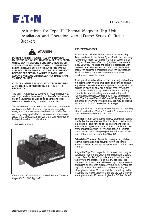
Effective July 2015 Supersedes I.L. 29C600C dated October,1999Instructions for Type JT Thermal Magnetic Trip Unit Installation and Operation with J-Frame Series C Circuit BreakersDO NOT ATTEMPT TO INSTALL OR PERFORMMAINTENANCE ON EQUIPMENT WHILE IT IS ENER-GIZED. DEATH, SEVERE PERSONAL INJURY, OR SUBSTANTIAL PROPERTY DAMAGE CAN RESULT FROM CONTACT WITH ENERGIZED EQUIPMENT.ALWAYS VERIFY THAT NO VOLTAGE IS PRESENT BEFORE PROCEEDING WITH THE TASK, ANDALWAYS FOLLOW GENERALLY ACCEPTED SAFE-TY PROCEDURES.CUTLER-HAMMER IS NOT LIABLE FOR THE MIS-APPLICATION OR MISINSTALLATION OF ITS PRODUCTS.The user is cautioned to observe all recommendations,warnings, and cautions relating to the safety of person-nel and equipment as well as all general and local health and safety laws, codes and procedures. The recommendations and information contained herein are based on Cutler-Hammer experience and judge-ment, but should not be considered to be all-inclusive or covering every application or circumstance which may arise. If any questions arise, contact Cutler-Hammer for further information or instructions.1. INTRODUCTIONMagnetic Trip Unit Type JTGeneral InformationTrip units for J-Frame Series C circuit breakers (Fig. 1-1) are available in two types: Type JT with thermal-mag-netic trip functions, described in this instruction leaflet;or Type JS electronic (Seltronic) trip functions, covered in l.L. 29C601. Trip units are listed in accordance with Underwriters Laboratories, Inc. Standard UL489 and satisfy the applicable requirements of the International Electrotechnical Commission Recommendations for molded case circuit breakers.The trip unit includes either a fixed or an adjustable ther-mal element for inverse time delay on overload and an adjustable magnetic element for protection against short circuits. In open air at 40°C, a circuit breaker with the trip unit installed will carry continuously a current (In)equal to the ampere rating marked on the trip unit nameplate without exceeding a 50°C rise at the termi-nals. The National Electrical Code (USA) requirements state that overcurrent protective devices may be loaded to a maximum of 80 percent of its rating (l n ).The trip unit cover is factory sealed to prevent tampering with the calibration. Tables 1-1and 1-2list catalog num-bers and electrical data for trip units.Thermal Trip:In accordance with UL standards require-ments the thermal element trips the circuit breaker with-in 2 hours for an overload of 135 percent and trips in less time for higher overloads. For all currents in excess of the magnetic setting, the tripping action is instanta-neous. In the overload trip region (up to 5 x In), the trip current times are the same for AC or DC.Adjustable Thermal:Trip units having an adjustable thermal element can be adjusted within the rangeshown in Table 1-2using a single adjusting button. (See Fig.2-5.)Magnetic Trip : The magnetic trip on each pole may be adjusted by turning the adjustment button with a screw-driver. (See Fig. 2-4.) Trip units are shipped from the factory with the buttons set in the low position. Themagnetic trip is calibrated at the factory to trip at an rms alternating current within plus or minus 10 percent of the high setting indicated on the trip unit nameplate, and within plus or minus 20 percent of the low setting. In the magnetic trip region (above 5 x In), the trip current levels are approximately 40 percent higher for DC than for AC.I.L. 29C600DInspect the trip unit for completeness, and check for damage before installing it in the circuit breaker frame.Trip unit center retaining screw is captive in the conductor; the two outer screws are installed in the circuit breaker frame.2-2. Remove circuit breaker cover screws and cover.2-3. Remove two screws from outer shunt plate inserts.(See Fig. 2-1.)The two trip unit outer screws may be placed in the trip unit conductor holes at this time. If preferred, a magnetic screwdriver may be used to position the screws when the trip unit is in the base.Make sure shunt plates are centered over shunt plate inserts. (See Fig. 2-1.)I.L. 29C600DEffective 7/15Trip units are calibrated at 40°C, 50/60 Hz and DC as noted. Consult Cutler-Hammer for derating at other frequencies and ambient conditions.Magnetic Calibration:The Series C magnetic calibra-tion is performed using a controlled ramp test method that should accurately reflect run-up test methods used in most field test procedures. The calibration is conduct-ed in a fixture essentially free of any magnetic influence.Some minor reductions (up to 10%) in the actual pick-up values could occur for circuit breakers mounted on steel surfaces.A controlled ramp test method generally produces more consistent results than a pulse test method because of the possible variables in the pulse method.Internal Accessories:The following types of circuit breaker internal accessories, which mount on the Type JT trip unit, are available for use. The number of the Instruction Leaflet covering the installation of each accessory is also shown.•Alarm (Signal)/Lockout (ASL) Switch l.L. 29C181 •121C 92 .L .l h c t i w S y r a i l i x u A •241C 92 .L .l p i r T t n u h S •Low Energy Shunt Trip l.L. 29C143•Undervoltage Release Mechanism l.L. 29C163(Handle Reset)•Undervoltage Release Mechanism l.L. 29C164(Manual Reset)For further information on the J-frame Series C circuit breaker, refer to l.L. 29C103. 2. INSTALLATIONThe installation procedure consists of inspecting and installing the trip unit. To install the trip unit, perform the following steps.If required, internal accessory installation should be done before the circuit breaker is mounted and con-nected. Refer to individual accessory instruction leaflets.2-1. Make sure that the trip unit is suitable for theintended installation by comparing nameplate data with existing equipment ratings and system requirements.Shunt Plate InsertsShunt PlatesFigure 2-1 Shunt Plates Centered Over Shunt Plate InsertsPage 2WHEN REMOVED AND REINSTALLED, THREAD-FORMING SCREWS TRY TO REFORM THETHREADS IN THE CIRCUIT BREAKER BASE. CARE SHOULD BE TAKEN EVERY TIME A THREAD-FORMING SCREW IS USED TO ENSURE THE SCREW STARTS IN THE ORIGINAL THREADS.DAMAGED THREADS CAN RESULT IN IMPROPER CIRCUIT BREAKER COVER RETENTION.When the trip unit is installed in a new circuit break-er frame, the remaining cover mounting hardware is supplied in a plastic bag with the frame.2-7. Install circuit breaker cover, and secure with pan-head screws followed by thread-forming screws as shown in Fig. 2-3.2-8. Reset circuit breaker by moving handle to the reset position. Move handle to the ON position. Circuit break-er should remain ON.2-9. Press PUSH-TO-TRIP button with a small screw-driver to check manual tripping of the circuit breaker.(See Fig.2-4.)NOTICEI.L. 29C600DEffective 7/152-4. Position trip unit in base. Make sure latch bracket pin is properly seated in slots in side plates. (See Fig. 2-2.) If necessary, pull latch towards load end of circuit breaker to help seat trip unit.DO NOT EXCEED A TORQUE OF 6 TO 8 LB-FT (8 TO 10 N.M.). EXCESSIVE TORQUING WILL SHEAR SCREWS.FAILURE TO APPLY THE REQUIRED TORQUE MAY LEAD TO EXCESSIVE HEATING AND CAUSE NUI-SANCE TRIPPING OF THE CIRCUIT BREAKER.2-5. Screw in and tighten three trip unit retaining screws (center first). Torque the screws to 6 to 8 Ib-ft (8 to 10N.m.). (See Fig. 2-2.)2-6. Install accessory(ies), if required.Figure 2-2 Trip Unit Installed in Circuit BreakerLatchSide PlateRetaining Screws Trip UnitSide Plate Latch Bracket !CAUTIONFigure 2-3 Cover Screw Installation PositionsScrew, .190-32 x 3.13 Inch, Pan-Head, Cross-Recessed Screw, No. 8 x 1.88 Inch, Pan-Head, Cross-Recessed,Thread FormingNote: Hatched Lines Show Additional Pole and Screws for 4-Pole Circuit Breaker.Page 3Torque the cover screws to 18-23 lb-in (2-2.6 N.m.).22222Style 6632C44H05Trip Unit Magnetic AdjustmentThe magnetic element of each pole of the trip unit can be adjusted by rotating the adjustment buttonson the front face of the trip unit with a screwdriver. The buttons have several settings as indicated on the name-plate with values in multiples of the trip unit ampere rat-ing (In) as shown in Fig. 2-5. To adjust the setting,rotate each button clockwise until arrow on button points to desired setting.2-10. Adjust magnetic pick-up settings as required. (See Fig.2-4.)Adjustment ButtonsTrip Unit Thermal AdjustmentIn some trip unit types, the thermal rating (In) of the trip unit can be adjusted by a single button (See Fig. 2-5)within the ranges indicated in Table 1-2. To adjust the setting, rotate the thermal adjustment button until the arrow on the button points to desired setting.2-11. Adjust thermal setting as required. (See Fig. 2-5.)Figure 2-4 Trip Unit Magnetic Adjustment Buttons Thermal Adjusting ButtonFig. 2-5. Typical Trip Unit With Adjustable ThermalTable 1-1. Trip Unit Catalog Numbers and ElectricalData - Fixed ThermalJT2070T JT3070T 70350 - 700JT2090T JT3090T 90450 -900JT2100T JT3100T 100500 -1000JT2125T JT3125T 125625 -1250JT2150T JT3150T 150750 -1500JT2175T JT3175T 175875-1750JT2200T JT3200T 2001000-2000JT2225T JT3225T 2251125-2250JT2250TJT3250T2501250-2500Also used with 4-pole circuit breaker. Load end adapter for neutral pole included in 4-pole frame (overcurrent protection for fourth pole not provided).Nameplate is marked in multiples of (l n), (that is, 5 to 10 times).Trip unit calibration complies with IEC requirements at 30°C.2-Pole©3-Pole 2Ampere Rating Trip Range(l n ) 30°C Ampere JT2125TA JT3125TA 125625 - 1250JT2160TA JT3160TA 160800 -1600JT2200TA JT3200TA 2001000 -2000JT2250TAJT3250TA2501250 -2500(overcurrent protection for fourth pole not provided).Nameplate is marked in multiples of (l n ), (that is, 5 to 10 times).Effective 7/2015Printed in Dominican Republic All Rights Reserved©2015 Eaton Corporation Eaton CorporationCutler-Hammer business unit 1000 Cherrington ParkwayMoon Township, PA 15108-4312USAtel: 1-800-525-2000 I.L. 29C600D3 3Page 423。
EPC-CPC安装及调试

其中
TYP AG 2591为马达型号, NR.为料号, s=+/-75mm为马达行程
Seite 16
2021/5/28
马达的安装 二、确认马达型号及行程后,查询下图:
AG2491
马 达 尺 寸 图
Seite 17
2021/5/28
马达的安装 AG2591
Seite 18
2021/5/28
马达的安装 AG2691
RK4004上操作面板使用 RK4004更改参数方法
1、确认 电压24v DC 后, 给RK4004上电,此时显示 2、按一下 SETUP 键
显示
Seite 30
2021/5/28
RK4004上操作面板使用 3、此时可通过 ▲ 、▼来选定设备,可进入0.1、0.2电
眼参数,对电眼参数进行设置
4、选定好设备地址后,按住SETUP 键不松手,再按▲ 或▼选定要进入的参数号,松开SETUP键后,显示的 值就是此参数号下的参数值,如 :进入3号参数,执 行3-42功能,按住setup键,通过▲ 、▼选择3,松开 setup键后,显示0,再按▲ ,到42,再同时按住 setup+ ▲ ,即执行3-42功能
2021/5/28
Seite 24
2021/5/28
Seite 25
2021/5/28
马达线配线 马达上回授板EK4002 配线接法:
简单总结: RK4004 的x2端子 与马达回授板上端 子1-6号 一一对应 屏蔽线接地处理
Seite 26
2021/5/28
配线 配线要求:
电源线 1 为+24v DC ,2 为 0v,3 为地线
如改25号参数为35: 按住setup不松手 按▲到25,松开setup键后,按▲到35后即更改成功
mec调试手册

S600顶峰系统调试手册西门子楼宇科技有限公司目录一、硬件部分 (1)1.MBC调试手册 (1)2.MEC调试手册 (8)3.传感器调试手册 (15)4.驱动器调试手册 (22)5.附表 (24)一、硬件部分1.MBC调试手册开始调试前,先确认电源模块、开放式处理模块和点模块已安装好且MBC电源处于关闭状态。
如MBC带扩展箱,则先调试MBC本箱,扩展箱慢调。
具体步骤为:1.通电前,先断开24V电源与MBC底板上的连接端口,用500V绝缘测试表做箱体的绝缘测试,并做好记录,绝缘测试如附表一;2.为确保MBC箱的接线正确,需安装需提供校线测试表,如附表二;3.用万用表检查所有点是否短路或对地短路,检查所有DO点的电压是否正确;4.检查所有端子是否整洁和套好套管;5.检查所有点是否按照接线图接线;6.检查MBC的模块是否正确插好,及地址码是否按图纸要求插好;7.检查MBC的进线电源是否正确,及经过变压器后的24V是否正确;8.安装MBC电源模块和开放式处理模块;9.打开开放式处理模块的前盖板即可露出锂电池,拉出隔离电池的聚脂薄膜。
用万用表量检测锂电池的电量,如无问题(3.6V),启用锂电池;注:在安装或拆除电源模块或开放式处理模块时,请先确认MBC的电源开关在关的位臵,否则有可能损坏电源模块或开放式处理模块。
通电前,先拔下进MBC底板的24VAC电源插头,用万用表测量其电源电压是否24VAC,且其下端是否与MBC箱体接地,如极性相反,会产即引起设备烧坏。
10.盖上开放式处理模块的盖板,合上电源。
检查开放式处理模块前的红色BATT LOW(低电池)灯是否亮,如灯亮则说明电池不足,需更换电池,直至此灯不亮为止;11.观察开放式处理模块上的STATUS(状态)灯是否闪烁,闪烁后做下一步,如不闪,则请参见MBC维护手册或找当地的西门子楼宇科技公司寻求支持;12.连接手提电脑、PC以及其它终端设备到开放式处理模块右侧的MMI口上,连接的终端设备必须与MMI口的通讯速率一致。
Eaton PDG22G0020TFFJ电源防御模块式电路保护器说明说明书

Eaton PDG22G0020TFFJEaton Power Defense molded case circuit breaker, Globally Rated, Frame 2, Two Pole, 20A, 35kA/480V, T-M (Fxd-Fxd) TU, Standard Line and Load (PDG2X2T100)Eaton Power Defense molded case circuit breakerPDG22G0020TFFJ 7866792141699 in6 in4 in5 lb Eaton Selling Policy 25-000, one (1) year from the date of installation of theProduct or eighteen (18) months from thedate of shipment of the Product,whichever occurs first.RoHS Compliant CSAUL 489IEC 60947-2CCC MarkedProduct NameCatalog Number UPCProduct Length/Depth Product Height Product Width Product Weight WarrantyCompliancesCertifications20 AComplete breaker 2Two-polePD2 Global Class A T-M (Fxd-Fxd) TU600 Vac600 VStandard Line and Load35 kAIC at 480 Vac 35 kAIC @480V (UL)20 kAIC Icu/ 15/13 kAIC Ics/ 42 kAIC Icm @525V South Africa (IEC)10 kAIC Icu @125 Vdc 10 kAIC Icu @250 Vdc36 kAIC Icu/ 36 kAIC Ics/ 75.6 kAIC Icm @380-415V (IEC) 55 kAIC Icu/ 55 kAIC Ics/ 121 kAIC Icm @240V (IEC) 65 kAIC @240V (UL)8 kAIC Icu/ 4 kAIC Ics/ 16.8 kAIC Icm @690V (IEC) 25 kAIC Icu/ 20 kAIC Ics/ 52.5 kAIC Icm @480V Brazil (IEC) 18 kAIC @600V (UL/CSA)30 kAIC Icu/ 22.5 kAIC Ics/ 63 kAIC Icm @440V (IEC)Eaton Power Defense MCCB PDG22G0020TFFJ 3D drawing Consulting application guide - molded case circuit breakers Amperage Rating Circuit breaker frame type Frame Number of poles Circuit breaker type Class Trip Type Voltage rating Voltage rating - max TerminalsInterrupt rating Interrupt rating range 3D CAD drawing packageApplication notesBrochuresPower Defense technical selling bookletPower Defense brochurePower Defense molded case circuit breaker selection posterPower Defense molded case circuit breakers - Frame 2 product aid CatalogsMolded case circuit breakers catalogCertification reportsEU Declaration of Conformity - Power Defense molded case circuit breakersPDG4 CCC certificationPDG4 CB reportPDG2 CB reportPower Defense Declaration concerning California’s Proposition 65 Installation instructionsPower Defense Frame 2 terminal kit - PDG2X3(2)(4)TA225RF instructions - IL012245EN H01Power Defense Frame 2 tunnel terminal (aluminum), 50A, 2 pole instructions - IL012236EN H02Power Defense Frame 2 tunnel terminal kits - PDG2X1TA225K instructions- IL012239EN H01Power Defense Frame 1 IEC and Frame 2 Rotary Mechanism with NFPA Handle Attachment Instructions (IL012260EN).pdfPower Defense Frame 2 global terminal shield, 2 pole - IL012330EN Power Defense Frame 2 tunnel terminal (aluminum), 100A, 2 pole instructions - IL012237EN H02Power Defense Frame 2 global interphase barrier 2 pole – IL012324EN Power Defense Frame 2 clamp terminal (steel), 20A, 2 pole instructions - IL012246EN H02Power Defense Frame 2 multi wire connector kit -PDG2X3(2)(4)TA2256W instructions - IL012242EN H01Power Defense Frame 2 PDG2 and PDC(E)9 breaker instructions -IL012106ENPower Defense Frame 2 screw terminal_end cap kit, 225A, 2 pole instructions - IL012257EN H01Power Defense Frame 1-2-3-4 IP door barrier assembly instructions -IL012278ENPower Defense Frame 2 terminal kit - PDG2X3(2)(4)TA150RF instructions - IL012244EN H01Power Defense Frame 2 tunnel terminal (aluminum), 150A, 2 pole instructions - IL012238EN H02Power Defense Frame 2 multi wire connector kit -PDG2X3(2)(4)TA2253W instructions - IL012243EN H01Power Defense Frame 2/3/4/5/6 voltage neutral sensor module wiring instructions – IL012316ENPower Defense Frame 2 locking devices and handle block instructions - IL012149ENPower Defense Frame 2 box terminal (steel), 100A, 2 pole instructions - IL012234EN H02Installation videosPower Defense Frame 2 withTMTU, Shunt Trip_UVR Animated Instructions.rhPower Defense Frame 2 TMTU Aux, Alarm, ST and UVR Animated Instructions.rhMultimediaPower Defense Frame 3 Variable Depth Rotary Handle Mechanism Installation How-To VideoPower Defense BreakersEaton Power Defense for superior arc flash safetyPower Defense Frame 5 Trip Unit How-To VideoPower Defense molded case circuit breakersPower Defense Frame 2 Variable Depth Rotary Handle Mechanism Installation How-To VideoPower Defense Frame 6 Trip Unit How-To VideoSpecifications and datasheetsEaton Specification Sheet - PDG22G0020TFFJTime/current curvesPower Defense time current curve Frame 2 - PD2White papersIntelligent circuit protection yields space savingsSingle and double break MCCB performance revisitedMolded case and low-voltage power circuit breaker healthMaking a better machineMolded case and low-voltage breaker healthSafer by design: arc energy reduction techniquesEaton Corporation plc Eaton House30 Pembroke Road Dublin 4, Ireland © 2023 Eaton. All Rights Reserved. Eaton is a registered trademark.All other trademarks areproperty of their respectiveowners./socialmedia。
- 1、下载文档前请自行甄别文档内容的完整性,平台不提供额外的编辑、内容补充、找答案等附加服务。
- 2、"仅部分预览"的文档,不可在线预览部分如存在完整性等问题,可反馈申请退款(可完整预览的文档不适用该条件!)。
- 3、如文档侵犯您的权益,请联系客服反馈,我们会尽快为您处理(人工客服工作时间:9:00-18:30)。
图 1.3 无钢板遮挡时
图 1.4 有钢板遮挡时
2 调试
2.1 系统配置
首先进入“运行监控”,手动状态下移动油缸,得到并记录“adc0 输入”一项的最 大值和最小值(即,获得位移传感器的最大值和最小值)。 然后进入“系统配置”菜单 ◇ 工作模式 : 11; ◇ 油缸行程 : 输入油缸的实际行程,单位 mm; ◇ 最小反馈 : 输入“adc0 输入”的最小值; ◇ 最大反馈 : 输入“adc0 输入”的最大值; ◇ 镜头参数 : 默认即可;
–7–
TPC600-EPC 安装调试手册
◇ adc 设置 : 默认即可; ◇ dac 设置 : 默认即可; ◇ gpio 设置 : 默认即可; ◇ 设备识别 : 默认即可。
2.2 参数设置
◇ 自动增益 1、2、3 : 对应自动控制过程中的 P、I、D; ◇ 对中增益 1、2、3 : 对应对中控制过程中的 P、I、D;
–3–
TPC600-EPC 安装调试手册
1 光电探测器
光电探测器与背光源配合探测带钢边缘,将边缘位置信息传递给纠偏控制柜,外形 如图 1 所示。
液晶屏
光圈
图 1 光电探测器外观
–4–
TPC600-EPC 安装调试手册
1.1 光电探测器安装
纠偏信号控制柜
光电探测器
L H1
辊道中心线
液压伺服信号 位移传感器信号
板带
பைடு நூலகம்
H2
背光源
图 1.1 纠偏安装示意图
纠偏系统安装及光电探测器安装示意图如图 1.1 和图 1.2 所示。 其中
L = 1/4(Wmax + Wmin ) H1 = 1200mm (推荐值) H2 < 400mm A = 14° 注: 光电探测器应尽量靠近收卷转向辊
L : 光电探测器镜头到辊道中心线的距离; H1 : 光电探测器镜头到钢板的距离; H2 : 背光源到钢板的距离; Wmax : 钢板最宽尺寸; W min : 钢板最窄尺寸.
–5–
TPC600-EPC 安装调试手册
L 辊道中心
A
H1
钢板
背光源
H2
图 1.2 光电探测器安装位置尺寸图
1.2 光电探测器调整
由于光电探测器中的线阵 CCD 对光线强度和入射光角度有一定要求,因此,还需 对光路进行调整。
① 角度调整。通过调整光电探测器的固定螺栓来调整角度,最佳状态:背光源无 遮挡时,光电探测器的液晶显示屏上的光强分布曲线为一条基本均匀的水平直 线。
3 附录 1 控制面板操作................................................................................................... 10 3.1 控制面板说明......................................................................................................... 10 3.1.1 信息显示........................................................................................................ 10 3.1.2 控制键:........................................................................................................ 13 3.1.3 功能键............................................................................................................ 13
–9–
TPC600-EPC 安装调试手册
3 附录 1 控制面板操作
3.1 控制面板说明
控制面板分为 信息显示、功能键、控制键三个区 3.1.1 信息显示
信息显示区左侧实时显示两路 DA 输出、两路 AD 输入信号的模拟值,蓝条越长, 数值越大。
5 附录 3. 电气连接............................................................................................................ 17
–2–
TPC600-EPC 安装调试手册
安全规范
根据在实际应用中的经验,板带控制系统的电气、机械设备是安全可靠的。 本规范是为了避免异常情况下人员伤害和财产损失。 注意: 为了避免损坏或破坏设备和设备部件,该信息必须严格遵守。 系统所有设备只能由有资质的人员进行运输、安装、连接、调试、维护和 操作,安装、调试前必须确认已经详细阅读本手册以及《TPC600用户手册》。 系统金属外壳须可靠接地。 合格人员应具备如下条件: • 有专业资质和相关经验; • 经过培训并完全熟悉板带控制系统和操作条件; • 能够发现和解决对系统电气、机械设备有潜在危害的现场接线、设备。
注 : 手动控制过程也加入了闭环控制,与对中控制共享 P I D; ◇ 标定参数 : 设置为 64; ◇ 错边偏移 : 开启错边功能时,该参数决定每层板带错开的距离; ◇ 错边层数 : 决定一个错边周期的层数; ◇ 中心偏移 : 默认即可。
2.3 方向设置
不同的工作方式和操作模式要求执行机构相对于板带的偏移方向作同方向或反方向的 运动: ◇ 自动模式:
② 光圈调整。通过调整光电探测器镜头的光圈,使得进入光电探测器的光量达到 一个适宜的状态。最佳状态:光电测头上的光强分布曲线的高度大概为整个屏 幕范围的 1/2。
–6–
TPC600-EPC 安装调试手册
调整完成后的光电探测器液晶屏幕上会有如图 1.3、图 1.4 所示: 液晶屏幕上方为状态栏,前四位为当前钢板边缘的编码,代表钢板边缘的位置。后 面的字符串为当前光电探测器镜头的状态。 edgepc_ok — 光电探测器光路正常,板带位置正常; no_steel — 光电探测器光路正常,无板带,或板带位置异常; opticalEr — 光路异常。
–8–
TPC600-EPC 安装调试手册
2.5 保存
完成上述步骤后,回到 系统配置 -> 保存参数,单击 确定,操作界面会回到主页,此 时,参数保存完成。同时建议用户另外自行备份参数。
2.6 故障检测
安装调试完成后,如果系统在工作时无法完成自动纠偏动作,或纠偏效果不理想时,可 按如下方法进行检测: ⑴ 读取系统参数,察看是否被人为改动; ⑵ 检查系统是否可正确执行 左移、右移、对中 操作; ⑶ 在如图 1.1 钢板位置放置边缘清晰整齐的遮光板,检查镜头状态是否为 edgepc_ok,
安装调试手册 型号:TPC600-EPC 日期:2010.5.10
TPC600-EPC 安装调试手册
–1–
TPC600-EPC 安装调试手册
目录
1 光电探测器........................................................................................................................ 4 1.1 光电探测器安装 ....................................................................................................... 5 1.2 光电探测器调整....................................................................................................... 6
4 附录 2 接线及开关设置............................................................................................... 14 4.1 拨码开关定义和设置............................................................................................... 15 4.2 连接端子定义和设置............................................................................................... 15
执行机构(一般为收卷机)需要与板带偏移方向同向运动,以达到所需效果。 ◇ 对中模式:
根据当前位移传感器的读数做出反应,驱动执行机构 正向 或 反向 运动,如果对 中方向错误,将永远无法回到中心点。 为直观方便,方向设置都由主板的拨码开关 S0 完成
2.4 标定
TPC600 采用模糊标定方式,操作者只需输入测量的结果,无需进行 复杂的计算处理。 ⑴ 确认完成前三步设置,并可正确执行 左移、右移、对中 操作; ⑵ 将系统置于 对中 模式,并确认油缸回到中位; ⑶ 在如图 1.1 钢板位置放置边缘清晰整齐的遮光板,并确认镜头状态为 edgepc_ok; ⑷ 将系统置于 自动 模式,沿背光源方向移动遮光板 64mm; ⑸ 测量油缸移动的距离 L,单位 mm,然后将 参数设置->标定参数的值改为 L。
2 调试...................................................................................................................................... 7 2.1 系统配置................................................................................................................... 7 2.2 参数设置 ................................................................................................................... 8 2.3 方向设置................................................................................................................... 8 2.4 标定 ........................................................................................................................... 8 2.5 保存........................................................................................................................... 9 2.6 故障检测................................................................................................................... 9
