RBS6601设备介绍
室分设计要求
室分设计要求1.1 室分器件使用原则优先选用基站信源+无源分布系统,合理选择信源设备,根据小区最大容量设计分布系统,保证系统的稳定性和可扩展性。
无源分布系统一二级主干的无源器件应采用高性能无源器件,确保系统的稳定可靠;天线、无源器件均采用兼容GSM/TD/WLAN/LTE的宽频设备可承载大功率的器件,兼容后续网络发展需要。
信源发射功率要求按照标称功率进行设计,不允许降低信源发射功率设计,特殊情况下可以适当使用负载,充分利用信源功率,将功率合理分配至覆盖区域。
RBS6601设备按标称功率设计时如果末端天线口功率过大,可以适当改用RBS2308设备作为信源,不允许使用衰减器。
馈线在功率足够的前提下尽量使用1/2馈线;主干路由必须使用7/8馈线,分支路由超过30米使用7/8馈线。
需参考《中国移动无源器件技术规范》和省公司对无源器件的整治要求,对器件使用明确要求。
1.以主设备(宏基站、微蜂窝和分布式基站)为信源的纯无源室内分布系统,通过FAS干扰分析软件确定无源互调干扰后,带测互调仪现场测试定位干扰源器件(五阶互调抑制比在-110dBm以上可判断有互调干扰)。
2.VIP站点出现明显干扰,而且有施工条件的,成批更换器件彻底消除无源器件隐患。
3.高配置系统(4载波以上)站点,为保障用户良好感知,应该使用高性能无源器件。
4.基站输出端器件一律采用DIN型接头,减少跳线多次转接带来差的互调影响;主干(7/8″馈线)一级器件用DIN型高性能无源器件,只在分支(1/2″馈线)二、三级器件用普通N型器件。
5.注入器件功率≥36dBm(单系统总功率)的无源器件替换成高性能的无源器件。
1.2 各类室分器件编号要求与损耗值规定1.2.1 器件编号与标注要求1.2.2 无源器件编号与标注无源器件编号采用按楼层编号的方式,编号格式为XXXX M-N F,其中XXXX为器件代码;M与N为阿拉伯数字,M表示器件的编号,不同楼层的器件数字编号均从1开始;N表示所在楼层,如果是地下楼层,则在楼层数字编号前加字母B,如B3F表示负三楼。
2-TD-LTE无线网络配置
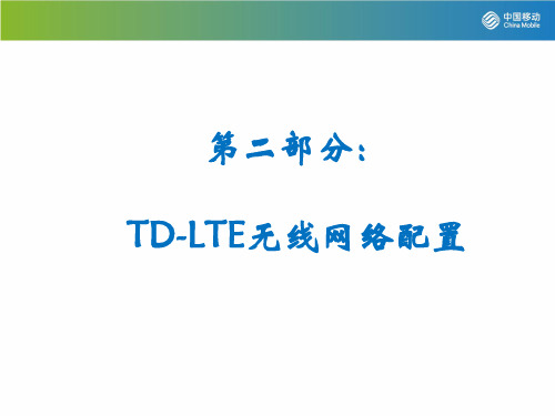
同步配置
ManagedElement
Equipment Subrack Slot PlugInUnit ExchangeTerminalIp GigaBitEthernet IpInterface=2
IpSystem
IpAccessHostEt
TransportNetwork
ENodeBFunction
第二部分:
TD-LTE无线网络配置
课程内容:
• E-UTRAN接口协议栈 • 操作维护配置 • 同步配置 • 硬件配置 • 传输网络配置 • 小区及邻区关系配置
LTE基站逻辑结构
天线单元组 X X X Sector Cell Cell RRU
X
X X 塔放
X
X X 塔放
天线单元组
网管 同步源 Mul
操作维护配置
ManagedElement 设置属性参数 logicalName.
Equipment Subrack Slot PlugInUnit ExchangeTerminalIp GigaBitEthernet IpInterface=1
IpOam
ENodeBFunction
RbsConfiguration Ip
ManagedElementData
RbsConfiguration
- ipAddress 业 务IP地址
TimingUnit
ntpServerAddressPrimar y -ntpServerActivePrimary
ossCorbaNameServiceAddress
-ntpServerAddressSecon dary -ntpServerActiveSecond ary - nodeLocalTimeZone
爱立信6601演示文稿

DUG各个接口的功能: GPS:提供GPS同步信号 EC:用EC线将DU与MU的连接 LMTA:操作维护端口(OMT接口) LMTB:SITE LAN(基站局域网)接口 ETA/ETB:;两路传输接口:E1/T1 ESB:ESB总线接口(TG同步用) A-F:与RRUS的CPRI接口。
爱立信RBS6601基站
陈伟
RBS6000基站描述
•
• • •
RBS6000基站的设计以支持大容量和多标准为基 本出发点。2010年推出的RBS6000系列基站主要 有2种类型: 室内宏站RBS6201 分布式基站RBS6601 RBS6000主要构成部分是数字处理单元 (Digital Unit)和射频单元(Radio Unit)。 数字处理单元主要包括基带信号处理模块及传 输接口;而射频单元是收发信机,完成射频信 号的处理。
RBS6601的RRUS(无线远端单元)
• RRUS 包含大部分无线处理硬件。RRUS 的主要部 分包括: • 收发器(TRX) • 发射器(TX)放大 • 发射器/接收器(TX/RX)转接 • TX/RX 过滤 • 电压驻波比(VSWR)支持 • ASC、TMA 与 RET支持 • 光纤接口
• 所有连接处于 RRUS 底部。RRUS必需垂直安装, 以适应温度范围。 • RRU 通过光纤电缆连接至 MU。MU 与 RRU 之间 的长度可以达到 40 千米。超过 20 千米的长度 则需要特殊光纤链路套件。 • 单元之间可以根据站点设置,通过不同的方式相 互连接。RBS 6601 支持: • 星状连接,每个 RRU 都与 MU 连接。 • 联级连接,MU 只与一个 RRU 使用一条光纤电缆 连接。其它 RRU 相互连接。当RRU相距MU较远时, 此解决方案能够减少所需的光纤电缆长度,并支 持多种应用。
爱立信RBS6601基站调测流程

爱立信RBS6601基站调测流程1.工具及软件笔记本电脑一台,必须带串口或USB转串口OMT线缆和读卡器以下是串口和水晶头转接数据线的做法:(水晶头的1,2,3与九针头母头5,3,2互接)2.电脑操作系统及应用软件的安装配置笔记本操作系统:Windows 2000 professional /Windows XP/Windows Vista注:OMT 最好不要安装在Windows7操作系统上OMT版本:RBS6601基站的集成测试所使用的OMT软件版本为R41H。
需要灌入CF卡的版本为29E。
3.硬件状态检查电源状态检查检查电源的类型,直流电还是交流电,电压是否正常。
(6601设备最好使用C32以下的空开或熔丝)。
硬件配置检查站型是否和设计文件一致扇区的配置是否和设计一致传输状态检查确认传输类型是否和设计文件一致传输线是否安装完成确认传输是否已连通4.本调及挂站串口线的一端连笔记本USB接口,另一端连RBS6601数字单元(DUG)上的LMT A 口。
其中CF卡是在BUG单元的侧面,需要用T-20把BUG拆出取卡。
RBS6601设备一般有3*4和3*8这2种配置。
不同的配置在硬件安装上也略有不同,下面将分别说明两种配置的硬件安装方面的区别和创建IDB的区别。
IDB的创建——配置为900MHZ,RUS载频数为3*4,机柜为66013*4的配置中,室外RRU单元3个,每个小区一个。
室内MU单元的BUG单元也只需要一个。
选择机柜型号,电源类型。
请根据现场情况,千万不能定错机柜及电源。
配置完成后点击“OK”确认。
机柜选择完成,开始选择antenna sector setup(天线扇区设置),点击New按钮。
选择本扇区RUS型号(RBS6601机柜900MHZ,RUS载频数为3*4为例),如下图所示。
配置完成后点击“OK”确认。
在最初的Create IDB确认配置,点击OK。
弹出配置各个扇区的TRX个数的界面,完成后“OK”确认。
爱立信 Inter-Frequency Offload异频负荷分担案例
爱立信Inter-Frequency Offload异频负荷分担案例----------校园场景昆明分公司无线网络优化中心1.场景描述近期,随着4G用户的普及,全国局部地方出现了话务由于某些活动引发激增,导致基站承载用户过多,进而出现系统异常的情况。
因此,对于高话务场景,需要针对现场实际用户规模,规划好网络覆盖方案,从而确保网络正常承载相应的话务。
目前高话务场景可以总体上划分为以下三类:1) 校园覆盖场景2) 演唱会场景3) 节日大型活动2. 校园场景特点高话务场景的特点是用户集中,对话务要求较高。
其中校园覆盖场景总体来说面积较大,高话务持续时间很长,具有长期性。
并且学生宿舍区域楼宇多且密集,楼梯建筑材料对无线信号屏蔽较强,局部区域存在室内弱覆盖现象。
另外,学生群体易于接受新业务,对数据业务的接受较快,对资费政策敏感,在数据业务大幅降低的情况下,数据业务增长极快。
校园高话务场景覆盖建设存在以下特点:1)学校开学迎新放号时用户群相比照拟集中;2)日常生活时用户群的移动特征明显,如不同时间在教学楼、食堂、宿舍之间的移动;3)深度覆盖困难,需要通过分布系统来解决信号问题;4)用户对效劳质量要求高,不能到达要求时造成投诉的可能性较大。
因此在解决校园高话务场景方面,主要从以下方面考虑:1)在保障用户接入的同时也需要确保用户感知,即每用户的速率情况;2)多区域的高密度话务需求;3)确保良好的信号覆盖,减少弱覆盖区域。
爱立信有一系列的容量提升和调度管理的相关功能,可更好的应对高话务场景的需求和冲击。
3.异频的负载分担IFO(interfrequencyoffload)可在同覆盖区域,eNB兼顾不同载波下的覆盖能力、传播特性等,将用户在不同载波间进行均匀分配。
该功能可以改善用户体验,降低拥塞概率,有效提升用户速率和容量。
3.1 IFO功能介绍IFO(interfrequencyoffload)异频负荷分担。
是IFLB异频负载均衡的备选功能。
RBS6601机架类型小区优化案例

DATE
PERIOD
CELLNAME
话务量
数据流量(MB)
TCH指配成功率
接入申请
S指配成功数
切换成功率
110505
07000800
金像电子A
11.06
32.89
99.83
3668.00
RBS6601机架类型小区优化案例
一、概述
RBS6601是爱立信专门设计用于帮助运营商面对日益复杂的网络挑战,最新推出的一款简易的射频拉远基站,主要由主单元(MU)与多个远端射频单元(RRUS)组成,二者通过光纤电缆连接,其单站容量可达24套载频,支持GSM3X8配置,每个RRUS包含4个载波。如下图:
针对以上推测,51803A的CHGR-0对应的RRU可能存在故障,而CHGR-3对应的RRU正常;为验证以上推断,将CHGR=0和CHGR=3对应的TG对换,将信道组对应的TG对换后,51803A的指标统计如下:
DATE
PERIOD
CELLNAME
话务量
数据流量(MB)
TCH指配成功率
接入申请
S指配成功数
10001100
金像电子A
3.59
0.00
13.41
0.00
0.00
21.53
110505
11001200
金像电子A
2.96
0.00
11.56
0.00
0.00
16.16
110505
12001300
金像电子A
3.30
0.00
19.72
0.00
SPD

系统说明:此系统主机可以实现:定时定曲播放,消防联动功能,自带8分区输出,可以实现一个相对较小的广播系统的功能实现、SPD-6601 智能中央控制器功能特点:SPD-6601可实现定时、分区、定节目及消防紧急广播等功能,系统可定时开启、关闭、自动运行所编程序、自动播放广播内容(背景音乐、铃声等),当紧急灾害发生时,系统可自动强行插入紧急广播。
可电脑联机操作,配有编程自动播放软件。
■内置4进8出的功率分区,实现自动或手动分区操作。
各分区可任意开启或关闭■内置MP3播放模块,外接U盘,即能实现定时自动播放■内置监听,可监听MP3播放声音■可以脱离电脑单独使用,也可以结合电脑一起使用,同时也可以配合远程寻呼站使用■设有10个可编程的快捷键,复杂操作,单键搞定■可以外控其它受控的周边设备:如DVD、调谐器TUNE、10路电源管理器等■可以编辑8种不同程序,每种程序均达220步。
每步操作精确到秒。
并设有特殊情况下运行程序,或不运行程序。
同时对于春夏秋冬不同季节运行的程序,只需简单配置即可■一路短路(消防全区报警)输入,一路可编程的短路输出(可以触发电源时序器等)■可配合无线遥控器SPD-6610P操作,空旷距离可达1000米■四路可控电源输出 4 x AC220V、SPD-6607 DVD播放器性能特点:■兼容DVD、CD、MP3等多种播放格式■直接选择曲目,荧光数码显示■具有通电后自动播放功能、SPD-6611 前置放大器性能特点:■10路输入(5路话筒、3路线路,2路紧急输入)■每路可独立音量控制,统一音量调节■高音和低音控制调节■信号LED电平指示、SPD-6360/6500/6650/6800 纯后级功放性能特点:◆提供RCA插口和XLR插口并接◆100V、70V定压输出或8欧定阻输出◆采用先进高效功率放大电路◆多种保护和警告功能◆输出短路、过流、过载保护告警〓规格参数〓、SPD-6623 电源时序器性能特点:■16路上电插座,立体连接■依次先后上电、开电、 EC-200 带前奏话筒、SPD-504 天花喇叭。
华为MINI机柜和华为嵌入式电源各设备接线说明

中国移动广西公司GSM16.1期基站工程MINI机柜和华为嵌入式电源各设备接线说明概述1、华为MINI机柜功能设备环境监控单元(EMUA)、热交换器(HEX)、热电制冷(TEC),需要用到3路直流电源空开,且目前只能通过MINI机柜中嵌入式电源取电。
2、华为目前提供的90A嵌入电源输出分路一次下电100A*1空开、40A*3空开,二次下电32A*2空开、16A*4空开。
3、华为目前提供的300A嵌入电源(配置250A)输出分路一次下电2×80A空开,1×100A空开,预留5路空开安装位置;二次下电1×32A空开,2×16A空开,1×63A空开,预留2路空开安装位置。
问题1、嵌入式电源一次下电输出分路不足,且空开容量大小不符合基站设备接入要求。
2、华为MINI机柜功能模块设备EMUA、HEX、TEC未明确接入空开位置。
3、MINI机柜功能模块设备接入嵌入式电源后,占用了3路嵌入式电源空开,将影响基站主设备接入和后期扩容设备接入。
解决1、华为为嵌入式电源MINI机柜站点提供DCDU-03B,扩展了9路一次下电输出分路。
2、明确了EMUA接入二次下电,HEX和TEC接入DCDU。
3、考虑到室外宏站设备2116和3900A场景,华为将90A嵌入式电源一次下电其中一路40A空开替换为63A空开;300A嵌入电源(配置250A)在一次下电预留位置增加一路63A 空开。
设备接入说明1、DCDU:接入一次下电100A*1(采用25平方毫米线径)2、RBS2116(-48V):接入一次下电63A*13、BTS3900A(-48V):接入一次下电63A*14、RBS6601(-48V):MU接入DCDU的20A*1,每RRU接入20A*15、DBS3900(-48V):BBU接入DCDU的20A*1,每RRU接入20A*16、环境监控单元(EMUA):接入二次下电16A*17、热交换器(HEX):接入DCDU的12A*18、热电制冷(TEC):接入DCDU的12A*1 接线图示。
RBS6601与RRUS相关告警

CF
2A
57 接收不均衡
当一个或多个TRUs在1440分钟内监 测到的RX PATH IMBALANCE的绝对值 大于6db时,出现2A 57告警(这种 告警在R12版本以上才会出现)。所 以此告警必须证实被处理好,因为 此告警不会在很短的时间内出现。 说明:有CF I2A:57告警时不一定伴 有CF I2A:33告警。 DUG与RRUS失去联系
TRXC2A TRXC2A TRXC2A
9 TX合成器不能锁定 10 TX内部电压故障 11 TX温度过高
TRXC2A TRXC2A
20 RX初始故障 25 TX最大功率限制
TRXC2A TRXC2A
TRXC2A
RX初始化启动失败 高温引起TX发射功率降低2dB,最 多可重复减少4dB,若持续高温输出 功率将会关闭,TX告警级别也将提 29 功率放大器故障 数据库中用来存储发射功率放大器 数据所使用的软件内部结构已经损 39 RF环路测试故障,RX降 坏 射频环路测试通过在TX与RX之间发 低 送空闲突发脉冲串序检测问题,一 个接收通路有故障时会引起告警 45 无线单元硬件错误 RRUS硬件内部故障
断电加电处理DUG/RRUS/RUS;替换 RRUS/RUS。 RRUS/RUS进行复位或断电加电处理; 否则替换RRUS/RUS。 断电加电处理RRUS/RUS;检查DUG与 RRUS/RUS的链接是否OK;插拔 RRUS/RUS的光纤、数据线或光电转换 模块;替换RRUS/RUS。 将其置入远端模式 断电加电处理DUG/RRUS/RUS;替换 RRUS/RUS。 检查连接RRUS/RUS的RX电缆;重新连接RX 电缆;替换 RX 电缆;若无效替换 参照TRXC I2A:20处理。 分集接收相关告警 分集接收相关告警 CF2A57相关告警 CF2A58相关告警 参照TRXC I2A:9处理。
RBS 6601 产品说明书
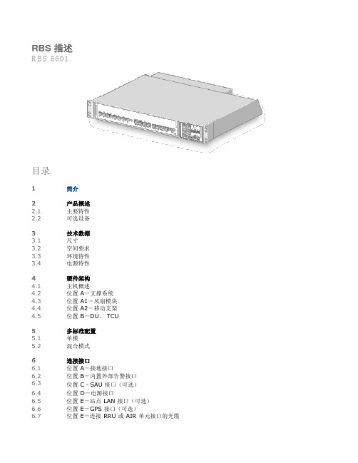
RBS 描述RBS 6601目录1简介2产品概述2.1主要特性2.2可选设备3技术数据3.1尺寸3.2空间要求3.3环境特性3.4电源特性4硬件架构4.1主机概述4.2位置 A-支撑系统4.3位置 A1-风扇模块4.4位置 A2-移动支架4.5位置 B-DU、 TCU5多标准配置5.1单模5.2混合模式6连接接口6.1位置 A-接地接口6.2位置 B-内置外部告警接口6.3位置 C-SAU 接口(可选)6.4位置 D-电源接口6.5位置 E-站点 LAN 接口(可选)6.6位置 E-GPS 接口(可选)6.7位置 E-连接 RRU 或 AIR 单元接口的光缆6.8位置 E-传输接口7传输标准7.1电以太网(WCDMA和LTE)7.2光以太网(可选)(WCDMA和LTE)8告警8.1用于外部告警的内置端口8.2SAU9标准、法规和可靠性9.1监管产品审批9.2可靠性9.3零备件版权Ericsson AB 2010 年至 2012 年版权所有。
保留所有权利。
未经版权所有者的书面许可不得以任何形式复制本文档。
免责声明由于方法、设计和制造不断发展,本文档的内容会有所调整,恕不另行通知。
爱立信不承担因使用本文档而造成的任何错误或损害的赔偿责任。
商标列表此处所述的所有商标为其各自所有者的财产。
如商标信息所述。
1 简介本文简要描述了 RBS 6601 主机。
安装射频拉远光缆解决方案介绍了连接到无线射频拉远单元 (RRU) 的光缆。
无线射频拉远单元描述对 RRU 进行了介绍。
2 产品概述RBS 6601 是一种射频拉远 RBS,也是 RBS 6000 产品系列之一。
RBS 6601 包含一个室内主机和多个RRU,放置在靠近天线或 AIR 单元的位置。
通过光缆将 RRU 或 AIR 单元连接到主机,如图 1 所示。
可提供标准长度的光缆,从几米到几百米不等。
还可使用租用光缆延长或构建光纤。
在这种情况下,必须考虑光纤的延伸和延迟。
5G基站产品介绍和工程建设方案2019

CPRI & digital signal processing
爱立信点系统通过产品 结构优化,头端轻量 化,数字信号集中处 理,比传统Hub-Prru结 构功耗可节省~50%
产品规格介绍—— DoT44 2.6G 100M v1
单频
设备型号 尺寸(宽×高×深)
尺寸(L) 重量(Kg) 供电方式(直流/交流/交直流)
5G 宏站
64TR AAS (天线+RU)
› 支持频段: 2515-2675 MHz › 通道数: 64T64R(32/16流) › 天线阵子数:192 › 工作频带宽度:160M › 输出功率: 240 W › EIRP:78.3 dBm(天线口总输出功率) › 尺寸: 961.5*509.5*178(mm) › 重量: 67 kg(含安装件) › 供电: -48V
多频多模一体化
三频
集成到一个
• 单根网线支持CAT6a 100米 • 一个安装点,单独打孔 • 业界最低功耗<50W • 业界体积最小 <1.8升,业界最轻 <1.5Kg
5G三频 单点 DoT
5G NR 4x4 MIMO +4G 2X2 MIMO*2 频段
Байду номын сангаас› IBW: 5G (2515-2675 MHz @100MHz)+4G (GSM/FDD B3 @25MHz+TDD B40 @50MHz)
产品规格介绍——DoT44 2.6G 100M v2
目前,一根网线16芯,其实相 当于两个设备
5G三频 DoT
5G NR 4x4 MIMO +4G 2X2 MIMO*2 频段
› IBW: 5G (2515-2675 MHz@100MHz)+4G (GSM/FDD B3 @25MHz+TDD B40 @50MHz)
WDMA RBS6xxx设备安装及调测注意事项

一、WCDMA RBS6601设备安装注意事项1、RBS6000配套的RRU类型为RRUS,该RRU安装基本上与RRUW01相同,但在电源接入上需要格外注意,RRUS电源接入与RRUW01不同,新款RRU格外多出一个电源接头,该接头的接法在箱单上有注明,直接按图安装就可以了,当要注意不要将电源正负接反图一、RRUS电源接口(母头)图二、RRUS电源接头(公头)图三、图中A口为-48V,B口为0V,接入时需格外注意2、关于RBS6000固定机架的安装该机架零件内有相关安装图纸,详细安装流程直接按图安装即可,但注意该机架最好在下面安装完成之后再固定到墙上去,具体图纸如下:3、GIE4805S(AC-DC)电源设备安装该设备为RBS6000供电的主设备,是在没有直接-48V电源柜的情况下使用,主要是将交流电转换为设备可以使用的直流电的供电设备,安装时直接挂到RBS6000设备的设备机架上即可,但需要注意该设备一共配备了2条电源线,一条是直接接到交流插座上的(20M),另外一条为直接连接在-48V直流机柜内的(10M左右)GIE4805S电源设备正面GIE4805S电源设备上面箭头所指部位为GIE4805S交流接入插座部分GIE4805S供电设备直流输出部分(为RBS6000设备供电部分)4、RBS6000 MU安装该主设备直接安装在机架内即可,具体安装按照图纸安装即可上图红线标记部分为RBS600 MU上图红线标记部分为RBS600 MU光纤接入部分图红线标记部分为RBS600 MU E1接入部分注:该E1接入部分只有2个网线接口,在OVP侧都接OVP-1网口,2M线侧还是需要做4条2M线RBS6000设备MU E1接入部分近图OVP内E1网线接入如图所示图中所示部分为RBS6000设备电源接入插座(-48V)如图所示为MU设备与GIE4805S专用连线(长度在30com左右)GIE4805S与MU连线在GIE4805S侧示意图GIE4805S与MU连线在MU侧示意,如图中B处,A处为EC BUS连线RBS6000设备安装完成各部分示意图注:RBS6000设备装货箱内配有外告相关配件,包括ALAM-OVP,OVP连线,耗材网线一捆以及2条MU电源连线(只能用到一条,另外一条暂时用不到),施工队在现场安装完毕之后,请注意妥善放置剩余的配件,如联通网建有需要可以将剩余部分配件统一存放管理,避免丢失二、WCDMA RBS6xxx设备调测注意事项注:在介绍RBSxxx设备的调测之前需要说明的是:所有的调测流程与RBS3xxx设备的调测基本相同,因此在一些相似的地方就不在赘言,本流程着重讲解RBS6xxx设备与RBS3xxx设备调测的不同之处1、检查DUW内软件版本因现在广东及海南已使用W10B版,但NB左出厂时可能预装最新版本如W11GA,所以在进行调测前先确定软件版本是否正确再进行调测,在MU加电前先确定DUW-RU/RRU之间连接线断开或RU/RRU为未加电状态,使用EM检查DUW内软件版本是否W10B(CXP9016867/3_R1J02),有关检查版本位置可参考以下图片。
HS6601L 用户手册说明书

HS6601L用户手册Ver:2.21.概述HS6601L是一款具有高性能的传感信号处理集成电路,内置LDO输出3.3V或2.5V,可以给PIR传感器探头供电。
它配以热释电红外传感器和极少量外接元器件构成被动式的热释电红外开关。
它能自动快速开启各类白炽灯、荧光灯、蜂鸣器、自动门、电风扇、烘干机和自动洗手池等装置,特别适用于企业、宾馆、商场、库房及家庭的过道、走廊等敏感区域,或用于安全区域的自动灯光、照明和报警系统。
2.特征◆CMOS工艺,低功耗◆内部滤波算法可有效抑制干扰◆内设延迟时间定时器和封锁时间定时器◆供电电压范围宽:A版(3.4~8V)、B版(2.6~8V)◆内置LDO输出:3.3V(A版)、2.5V(B版)◆SOP8封装3.应用◆自动灯光开启◆报警系统开启◆自动门、烘干机开启◆自动洗手装置等4.脚位信息4.1管脚图4.2管脚说明引脚名称I/O 功能说明1VDD P 工作电源正端2VLDO O LDO 电压输出端3PIRIN I PIR 信号输入端4GND P 工作电源负端5REL O 控制信号输出端,高电平有效6ONTIME I 定时调节端7SENSE I 距离调节端8CDSI光控输入端当CDS<0.5V 时禁止触发;CDS>1.0V 时允许触发5.结构框图6.极限参数(除特殊说明:Tamb=25℃)参数符号参数范围单位电源电压V DD0-8V输入电压V IN Vss-0.3~V DD+0.3V输出电压REL UT Vss-0.3~V DD+0.3V最大输出电流I OUT10mA存储温度T stg-40~+125℃工作温度T opr-20~+70℃7.电气参数(除特殊说明:Tamb=25℃)符号参数测试条件最小值最大值单位VDD 工作电压范围(A版)--3.48V 工作电压范围(B版) 2.68IIDLE 待机电流(A版)无负载17uA 待机电流(B版)14V RH CDS端输入高电平--1.0VVRLCDS端输入低电平0.5VRELH REL端输出高电平(A版)VLDO=3.3V,IOH=10mA3.0V REL端输出高电平(B版)VLDO=2.5V,IOH=10mA2.25RELL REL端输出低电平(A版)VLDO=3.3V,IOL=10mA0.33V REL端输出低电平(B版)VLDO=2.5V,IOL=10mA0.25。
RS-660 通信管理机说明书

RS-660通信服务器1概述RS-660通信服务器和当地计算机、保护测控设备、综合测控单元一起构成发电厂、变电站自动化系统,是综合自动化系统的重要组成部分。
与站内的保护和测控单元通过CAN网、485或以太网进行通信,可同时与当地监控计算机和远方相连,构成当地计算机监控系统和完成远方调度系统功能;可以收集站内所有保护/测控/IED装置的信息。
串行通信口与其他装置的接口可以是隔离的RS-232接口,也可以是隔离的RS-485接口。
根据现场需要,用户也可以定制其他的接口,如长线驱动、光纤接口、以太网接口等。
串行口的通信规约也可以根据现场的实际需要进行配置,目前支持103、101、DL451-91(国标 CDT)、POLLING等各种标准通信规约,并可根据用户要求进行特殊规约的开发。
由于通信服务器是免维护设备,装置取消了人机界面联系。
软件采用了填表式组态软件,通过计算机一次性对全站的组态设置完毕。
1.1装置的主要功能装置具有与当地监控计算机系统通信的功能,采用基于TCP/IP协议的10M/100M 以太网通信,应用层采用IEC 60870-5-103国际标准通信规约;装置具有与保护测控装置及综合测控单元通信的功能,采用以太网通信;装置具有和其他智能设备通信的能力,采用串口通信;装置具有与远方调度系统通信功能,完成遥信、遥测、遥控、遥调等功能,可通过一个或者更多RS-232C口或RS-485C口实现,支持IEC 870-5-101、IEC 870-5-102、IEC 870-5-103、IEC 870-5-104、SC1801、DL451-91(国标 CDT)、POLLING等各种标准远动通信规约,并可根据用户要求进行特殊规约的开发;装置在直流电源掉电时,时钟、参数均不丢失;通信监视功能,通过运行在PC机上的调试终端软件监视本机工作状态及各个通信接口的通信数据;自诊断功能,装置在开机时进行自我检测;自恢复功能,在受到外界干扰或其他原因导致程序运行出错时,系统能在一定的时间内自行恢复。
应用新技术解决4G疑难站址研讨会-解决方案集-爱立信厂家

功耗 工作频带宽度 滤波器带宽及范围 TD-L工作频率范围 输出功率(例:8*10W) 光纤接口(个数×速率) 光纤拉远距离
级联情况
RRU接头方式(N型/集束/其他)
是否能当两个单通道的RRU使用
D频段2通道 RRU 2208 B41E 200x200x72mm(带天线)
设备型号 尺寸(宽×高×深)
尺寸(L) 重量(Kg) 供电方式(直流/交流/交直流)
功耗 工作频带宽度 滤波器带宽及范围 TD-L工作频率范围 输出功率(例:8*10W) 光纤接口(个数×速率) 光纤拉远距离
级联情况 RRU接头方式(N型/集束/其他) 是否能当两个单通道的RRU使用
E频段2通道 RRU 2216 B40A 277x377x108
机房 扩容 网络融合
建设成本
宏站及室分补 点 难 复杂 长 难 需要 容易 一般
投入产出比低、 包含设备、集
成等费用
mRRU
简单 简单 短 简单 不需要 一般 宏微协同
只含设备
9
疑难站点解决方案和应用案例-新产品
四、Relay
• 覆盖解决方案的具体描述:
利用频谱优势,使用不同频段解决基站S1/X2回传的方案来缓解解决深度覆盖面临的网络建设难题,可作为
无光纤场景下的站点回传方案。
• 产品特点,可以解决哪方面的困难,解决思路是什么;
产品体积小,仅3L,安装灵活方便;内置天线,不占用天面空间;通过CPE回传来缓解解决深度覆盖和传输
采用RRU 2208 B41E内置天线 ,安装在灯杆站上,覆盖街道或改善室内覆盖。
• 产品特点,可以解决哪方面的困难,解决思路是什么;
RBS6601技术指标

一 MU 参数只能接-48V 直流MU接电源只能接-48VMU接外部告警MU 到RRU的光纤连接MU 上的2M传输连接可以接2个PCM传输Dimensions MU尺寸Height 66 mm (1.5 U)Width 483 mm (19-inch)Depth 350 mmFor more information about dimensions, see Figure 3.WeightMain unit fully equipped < 10 kgColorWhite Reference number: NCS S 0502-B Maximum power consumption, main unitDU Configuration Maximum power dissipation, main unit1 x DUW 405 W (MU最大功耗)DC Main Power Minimum Fuse Rating and Cross-Sectional CableAreas Maximum Fuse Rating and Cross-Sectional Cable AreasFuse Rating Recommended for Reliable Operation (A)(1)Cross-Sectional CableAreaAllowed Fuse Rating(A)(2)Cross-Sectional CableAreaDC-powered-48 V, two-wire15 (with 1 x DUW) 4 mm2(3)20 (MU 需要的镕丝) 4 mm2(3)(1) The recommended fuse rating corresponds to peak load and depends on the DU configuration.(2) Absolute maximum fuse class in accordance with RBS design restrictions.(3) Standard cable delivered with RBS 6601二 RRU 参数设备本身仅支持直流-48V, 如接230V, 需加PSU和 ACCU. (1个RRU支持4个TRX)PSU 将ACCU 输出的AC交流转变成DC直流The PSU is required for the AC power input option. It converts RRUW input main power 100 - 250 V AC to -48 V DC. It is installed on the back side of the RRUW.ACCU 输入AC交流输出AC交流The ACCU is required when the PSU is used and the RRUW is installed outdoors. It houses the SPD. It is installed on the back side of the RRUWPosition InterfaceA AC power supply cable (input gland)B Equipotential Bounding Terminal (EBT)C AC power jumper cable to PSUMU 和 RRU接口Position Description LabelA Optical indicators F, O, I, Data 1, and Data 2B -48 V DC power supply PowerC Line Maintenance Terminal (LMT) LMTD Optical cable 1 IN Data 1E Optical cable 2 OUT Data 2F Antenna 1 RF AG Antenna 2 RF BH RET ALD ctrlJ External Alarm Ext AlarmK Cross Connect RXA RXA I/OL RXA Cosite RXA OutM Cross Connect RXB RXB I/ON EBT EBT。
RB600系列变频器说明书
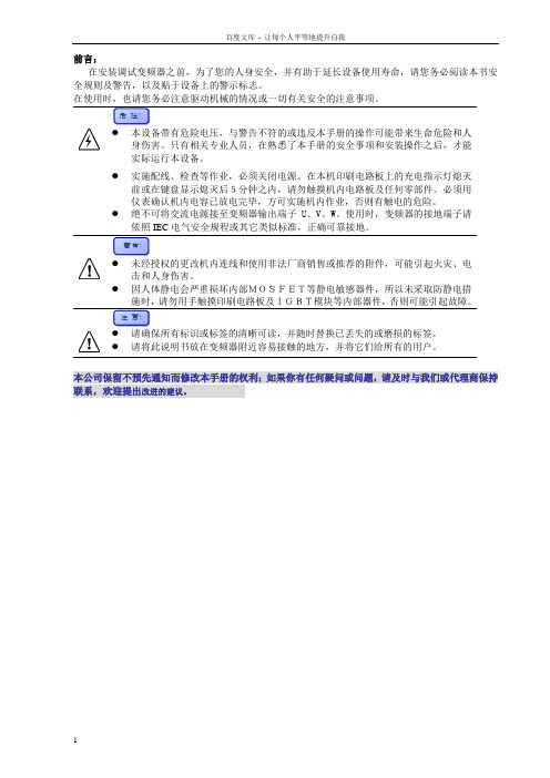
在安装调试变频器之前,为了您的人身安全,并有助于延长设备使用寿命,请您务必阅读本书安全规则及警告,以及贴于设备上的警示标志。
实际运行本设备。
●实施配线、检查等作业,必须关闭电源。
在本机印刷电路板上的充电指示灯熄灭前或在键盘显示熄灭后5分钟之内,请勿触摸机内电路板及任何零部件。
必须用仪表确认机内电容已放电完毕,方可实施机内作业,否则有触电的危险。
●绝不可将交流电源接至变频器输出端子U、V、W。
使用时,变频器的接地端子请依照IEC电气安全规程或其它类似标准,正确可靠接地。
●因人体静电会严重损坏内部MOSFET等静电敏感器件,所以未采取防静电措●请将此说明书放在变频器附近容易接触的地方,并将它们给所有的用户。
本公司保留不预先通知而修改本手册的权利;如果你有任何疑问或问题,请及时与我们或代理商保持联系,欢迎提出改进的建议。
1 产品简介…………………………………………………………1-1RB600 …………………………………………………………1-1储存运输………………………………………………………1-3开箱检查………………………………………………………1-32 技术规范…………………………………………………………2-1规格尺寸………………………………………………………2-1技术规范………………………………………………………2-33 安装配线…………………………………………………………3-1安装环境………………………………………………………3-1机械安装………………………………………………………3-1电气安装………………………………………………………3-24 操作运行…………………………………………………………4-1键盘操作………………………………………………………4-1参数修改………………………………………………………4-3参数监视………………………………………………………4-5初步运行………………………………………………………4-55 功能参数…………………………………………………………5-1功能简表………………………………………………………5-1详细功能………………………………………………………5-96 故障排除…………………………………………………………6-1故障查询………………………………………………………6-1故障代码………………………………………………………6-2异常处理………………………………………………………6-37 电磁兼容…………………………………………………………7-18 选件/附件………………………………………………………8-19 应用实例…………………………………………………………9-110保养维护…………………………………………………………10-1附录一:RS485串行通讯协议附录二:名词索引RB600是用于控制三相交流电动机的变频调速器。
RBS6601 Description

RBS DescriptionRBS6601DESCRIPTIONCopyright©Ericsson AB2010.All rights reserved.No part of this document may be reproduced in any form without the written permission of the copyright owner. DisclaimerThe contents of this document are subject to revision without notice due to continued progress in methodology,design and manufacturing.Ericsson shall have no liability for any error or damage of any kind resulting from the useof this document.Trademark ListAll trademarks mentioned herein are the property of their respective owners. These are shown in the document Trademark Information.Contents Contents1Introduction12Product Overview1 2.1Main Features2 2.2Optional Equipment23Technical Data3 3.1Dimensions3 3.2Space Requirements4 3.3Environmental Characteristics5 3.4Mains Supply Characteristics8 3.5System Characteristics94Hardware Architecture10 4.1Main Unit Overview10 4.2Position A-Support System11 4.3Position A1-Fan Module11 4.4Position A2-Movable Brackets11 4.5Position B-DU115Connection Interfaces11 5.1Position A-Earth Grounding Interface12 5.2Position B-Built-in External Alarm Interface13 5.3Position C-SAU Interface(Optional)14 5.4Position D-Power Interface14 5.5Position E-Site LAN Interface(Optional)15 5.6Position E-GPS Interface(Optional)16 5.7Position E-Optical Cables to the RRU Interface17 5.8Position E-Transmission Interface196Transmission Standards19 6.1Ethernet,Electrical(WCDMA and LTE)20 6.2Ethernet,Optical(Optional)(WCDMA and LTE)20 6.3E1,T1,and J1(WCDMA only)21 6.4E1and T1(GSM only)22RBS Description6.5STM-1(WCDMA only)227Alarms237.1Customer-Specific External Alarm238Standards,Regulations,and Dependability248.1Regulatory Product Approval248.2Dependability268.3Spare Parts26Product Overview 1IntroductionThis document is a general description of the RBS6601main unit.A descriptionof the optical cables to the Remote Radio Units(RRUs)can be found inInstalling Optical Cables for Main-Remote Solutions and a description of theRRUs can be found in Remote Radio Unit Description or Technical ProductDescription,RRU.2Product OverviewThe RBS6601is a main-remote RBS and a member of the RBS6000family.The RBS6601consists of an indoor main unit and a number of RRUs designedto be located near the antenna.An optical fiber cable connects each RRUto the main unit,as shown in Figure1.The optical fiber cable is available instandard lengths in the range of300m.The fiber network can also be extended or built using leased fiber networks.Inthis case the extension and delay of the fiber network must be considered.Theequivalent supported distance between the main unit and the RRU is then40km for WCDMA.For LTE and GSM,consult the market representative.RBS DescriptionFor WCDMA the RBS is in the normal case configured with up to three sectorswith up to four carriers.For GSM the normal case is up to three sectors withup to eight carriers and for LTE the normal case is up to three sectors.Thenumber of RRUs supported depends on the available radio configurations.The configurations currently available are described in RBS Configurations orCable Diagrams.Figure2shows the main unit with Digital Unit WCDMA(DUW).Figure2RBS6601Main Unit with DUW2.1Main FeaturesThis section describes the main features of the RBS.Note:Not all features are supported by all RBS configurations.The main features of the RBS6601are the following:•Includes a subrack based main unit to be hosted in a19-inch rack structure, either an existing RBS or other standard racks•Has-48V DC(two-wire)power supply•Supports external Global Positioning System(GPS)•Supports integrated external alarms2.2Optional EquipmentThe equipment presented in this section is optional and can be orderedseparately.It is not necessary for basic RBS functions.The equipment is located outside the RBS.Technical DataExternal SAUThe Support Alarm Unit(SAU)is an alarm and connection unit that is externallyinstalled in a distribution frame that also includes Overvoltage Protection(OVP)for external alarms and transmission.ASC,TMA,RETU,and RIUThe following mast-located units are placed close to the antenna:•Tower Mounted Amplifier(TMA)•Antenna System Controller(ASC)•Remote Electrical Tilt Unit(RETU)•RET Interface Unit(RIU)The TMA and the ASC are uplink amplifiers and improve the RX sensitivity.The RETU enables remote tilt of the antenna system.A RETU can beconnected directly to an RRU or through an ASC or an RIU.3Technical DataThis section describes the physical characteristics,environmental data,andthe power supply of the RBS.3.1DimensionsTable1lists the dimensions,weight,and color of the main unit.Table1Dimensions,Weight,and ColorDimensionsHeight66mm(1.5U)Width483mm(19-inch)Depth350mmFor more information about dimensions,see Figure3.WeightMain unit fully equipped<10kgRBS DescriptionColorWhite Reference number:NCS S0502-BFigure3Dimensions3.2Space RequirementsThis section describes the space requirements for installing the main unit in a19-inch rack.3.2.1Installation RequirementsThe main unit is1.5U high and can be installed top or bottom aligned in a19-inch rack that complies with IEC60297.Two main units can be installeddirectly above each other.The minimum distance between the rear of the main unit and the rear rackwall is50mm for the exhaust air.If the rack is equipped with a door,theminimum distance is50mm between the front of the main unit and the door,to provide space for cables and air intake.The main unit's movable bracketscan be adjusted up to80mm horizontally to place the main unit in the bestposition in the rack.3.2.2Site LayoutThe main unit can be installed in free-standing racks or cabinets,withoutcontact with other cabinets,against a wall or back to back or side to side withother rmation regarding placement of cabinets can be found inthe manual for the cabinet.Technical DataA minimum distance of200mm must be left between the top of the rack andthe cable ladder and a minimum distance of300mm between the ceiling andthe cable ladder is required to provide adequate working space and to ensuresufficient airflow,see Figure4.Figure4Cable Ladder Installation RequirementsA minimum space of1m is recommended in front of the rack to provideadequate working space.3.3Environmental CharacteristicsThis section describes the environmental characteristics of the RBS.3.3.1Operating EnvironmentThe following is a list of values for the main unit normal operating environment:Temperature+5to+50 CRelative humidity5to85%Absolute humidity1to25g/m3Maximum temperature change0.5 C/minRBS Description3.3.2Heat DissipationThe heat dissipation values listed in this section are intended only to form thebasis of the dimensioning of the site-cooling system.The heat dissipationdepends on the DU configuration which is shown in Table2.Table2Maximum Heat Dissipation,Main UnitDU Configuration Maximum Heat Dissipation,Main Unit1x DUW295W2x DUG135W2x DUL240W3.3.3Acoustic Noise for Main UnitThe acoustic noise levels corresponds to a free standing(not built-in)main unitand are measured for typical traffic in accordance with ISO3741,as describedin Table3.Table3Maximum Sound Power LevelTemperature( C)Sound Power Level(L WA in Bel)+20 C 5.8+25 C 5.8+30 C 5.8+45 C 6.03.3.4Ground VibrationThe following is a list of values of the RBS main unit resistibility to groundvibrations:Random vibration,normal operation Maximum0.02m2/s3Maximum0.08m2/s3Random vibration,exceptionaloperationRandom vibration,non-destruction Maximum0.15m2/s3Random vibration,shock Maximum40m/s250m/s2within2to5HzNon-destructive seismic exposure,maximum level of Required ResponseSpectrum(RRS)(1)Technical Data Non-destructive seismic exposure,test1Hz to35HzfrequencyVerteq IINon-destructive seismic exposure,time history(1)Defined in EN300019-2-3.3.3.5Earthquake RequirementsTo fulfill earthquake requirements,follow the instructions in the manual forthe rack.3.3.6MaterialsThe materials in the RBS are managed through the Ericsson lists of bannedand restricted substances,based on legal and market requirements.RBS Description3.4Mains Supply CharacteristicsThis section describes the power supply,power consumption,and fuse andcircuit breaker recommendations.3.4.1DC Power Supply CharacteristicsThe main unit is available with a two-wire-48V DC power interface,as listed inTable4.Table4Power SupplyConditions Values and RangesNominal voltage-48V DCOperating voltage range-40.0to-57.6V DCNon-destructive voltage range0to-60V DC3.4.2Power ConsumptionThe power consumption of the main unit depends on the DU configuration.Thefigures presented in Table5also includes power to an external SAU(10W).Note:The following figures represents the maximum peak power consumptionand shall not be used for calculation of average energy consumption.Table5Maximum Power Consumption,Main UnitDU Configuration Maximum Power Consumption,Main Unit1x DUW305W2x DUG145W2x DUL250W3.4.3Fuse and Circuit Breaker RecommendationsThe main unit external DC mains fusing must meet the following characteristics:•Fuse,type gL-gG-gD,in accordance with IEC/EN60269-1and UL248-8•Circuit breaker in accordance with IEC60947-2and UL489AThe fuse and cable recommendations given in Table6are based on peakpower consumption and give no information about power consumption duringnormal operation.The minimum fuse rating depends on the DU configuration.If the node configuration is a dual support system configuration,each supportsystem requires a separate DC in cable and fuse.Technical DataTable 6Fuse and Circuit Breaker RecommendationsMinimum Fuse Rating and Cross-Sectional Cable Areas Maximum Fuse Rating and Cross-Sectional Cable Areas DC Main PowerFuse Rating Recommended for Reliable Operation (A)(1)Cross-Sectional Cable AreaAllowed Fuse Rating (A)(2)Cross-Sectional Cable Area15(with 1x DUW)6(with 1or 2DUG)DC-powered -48V,two-wire15(with 1or 2DUL)4mm 2(3)204mm 2(3)(1)The recommended fuse rating corresponds to peak load and depends on the DU configuration.(2)Absolute maximum fuse class in accordance with RBS design restrictions.(3)Standard cable delivered with RBS 66013.5System CharacteristicsThis section describes the system characteristics of the RBS.3.5.1RF Electromagnetic ExposureGeneral information about Radio Frequency (RF)Electromagnetic Fields (EMF)can be found in Radio Frequency Electromagnetic Fields .Information about radio access specific compliance boundaries forelectromagnetic exposure can be found in Radio Frequency Electromagnetic Exposure .3.5.2SoftwareInformation about software dependencies can be found in Compatibilities for Hardware and Software .3.5.3Radio ConfigurationsInformation about available radio configurations can be found in RBS Configurations or Cable Diagrams .RBS Description4Hardware ArchitectureThis section contains information about both mandatory and optional hardwareunits,based on a fully equipped main unit.Note:The currently available configurations are described in RBSConfigurations or Cable Diagrams.4.1Main Unit OverviewThis section contains an overview of the standard hardware units required,regardless of configuration or frequency.Figure5shows the location and Table7describes the hardware units in themain unit.Figure5Location of Hardware Units in Main UnitTable7Hardware Units in Main UnitPosition Name of Units Number of UnitsA Support System1A1Fan Module1A2Movable Brackets2B DU(1)1-2(1)Depending on the DU versionConnection Interfaces4.2Position A-Support SystemThe support system controls the climate system including the fans.The supportsystem is also a DC interface for the RBS and distributes power to the DUs andto the external SAU.An external EC bus and built-in alarms is supported.Note:For WCDMA,it is possible to extend the main unit with a secondsupport system in a dual support system,where two connected supportsystems constitute one RBS.The support systems in the RBS host oneDUW each.The fans in the primary and the secondary support systemare both controlled by the DUW in the primary support system.Eachsupport system provides power to its hosted DUW.All other externalRBS connections are made to the primary DUW and support systemonly.For GSM or LTE it is possible to put2DUs in the same support system.4.3Position A1-Fan ModuleThe fans are located in a replaceable fan module at the back of the main unit.The fans cool the DU and the support system's internal electronics.4.4Position A2-Movable BracketsThe movable brackets can be placed in a0mm,a58mm,or an80mm positionfrom the front to ensure that the main unit fits in racks with different depths.4.5Position B-DUThe DU provides switching,traffic management,timing,baseband processingand radio interface.More information about DU can be found in Digital Unit Description.5Connection InterfacesThis section contains information about the external connection interfaces ofthe main unit.Figure6shows the location and Table8describes the connection interfaces.RBS DescriptionFigure6Connection Interface LocationsTable8Connection InterfacesPosition DescriptionA Earth grounding interface(positioned at the back of the main unit)B Built-in external alarm interfaceC SAU power interfaceD Power connection interfaceE DU with interfaces to:•LAN interface•GPS interface•Optical cable interface to the RRU•Transmission5.1Position A-Earth Grounding InterfaceAll equipment must be connected to the same site Main Earth Terminal(MET)inside the equipment room using a16mm2earth grounding cable.The earth grounding point is located on the back of the main unit and consistsof an M8screw,nut,and washers as shown in Figure7.Connection InterfacesFigure7Earth Grounding Interface5.2Position B-Built-in External Alarm InterfaceThe main unit supports8built-in alarm ports for customer specific externalalarms.An alarm can be triggered by an open or closed condition.The external alarms are connected to a8x2pole detachable socket connector,as shown in Figure8.Figure8Built-in External Alarm InterfaceRBS Description5.3Position C-SAU Interface(Optional)The SAU is optional and is installed outside the cabinet.Power is supplied fromthe main unit to the SAU via the10pole RJ-45connector as shown in Figure9.Figure9SAU Interface5.4Position D-Power InterfaceIncoming two-wire-48V DC power is connected by a two-pole connector.Thepower cable must have a cross-sectional area of4mm2.The main unit must beconnected to an external fuse.More detailed information about cross-sectionalcable areas and fuse sizes can be found in Section3.4on page8.The connection interface is shown in Figure10.Connection InterfacesFigure10Power Connection Interface5.5Position E-Site LAN Interface(Optional)In WCDMA the Site LAN,and in LTE the Local Maintenance Terminal(LMT),isused to communicate with the RBS Element Manager(EM).A client can beconnected to the DU for communication and service purposes through theRBS EM.In GSM,Site LAN is used to communicate with the Operation and MaintenanceTerminal(OMT).The Site LAN interface in the DU occupies port LMT B and consists of an RJ-45connector as shown in Figure11.RBS DescriptionFigure11Site LAN Interface in DU5.6Position E-GPS Interface(Optional)The RBS can be optionally connected to a GPS unit,which is used for timingsynchronization of the RBS.The GPS interface in the DU consists of an RJ-45connector as shown inFigure12.Connection InterfacesFigure12GPS Interface in DU5.7Position E-Optical Cables to the RRU InterfaceThe connection between the main unit and the RRU is made by an optical cablethrough an Supported Small Form-factor Pluggable(SFP)module.Severaldifferent lengths of the optical cable are available between5m and250m.For longer distances between the main unit and an RRU and for greaterconnection flexibility in general,an existing optical fiber transmission networkcan be used to increase the total length of the optical cable.Optical cables areconnected to the optical fiber transmission network by a connection box.The supported scenarios for connection of optical cables between a main unitand an RRU are shown in Figure13.RBS DescriptionFigure13Optical Cables Connection ScenariosThe optical cable interface on the main unit is shown in Figure14.Figure14Optical Cable InterfaceSpecific information about optical cables,can be found in Installing OpticalCables for Main-Remote Solutions.Transmission Standards5.8Position E-Transmission InterfaceSeveral transmission alternatives are available.The alternatives with theircorresponding cable types are described in Section6on page19.6Transmission StandardsThis section describes the transmission standards supported by the RBS.The following transmission alternatives are available:•Electrical Ethernet transmission(WCDMA only)•Optical Ethernet transmission(WCDMA only)•E1/T1/J1,electrical transmission(WCDMA only)•E1/T1,electrical transmission(GSM only)•STM-1(Synchronous Transport Module level-1)(WCDMA only)The transmission standards are listed in Table9.Table9Transmission StandardsTransmission Standard TransmissionCapacity(Mbps)Cable Impedance( )Cable Type Physical LayerEthernet(electrical)100/1,000100Balanced lines IEEE802.3-100/1000Base-T Ethernet(optical)1,000Max attenuation0.5dB/cablingOptical fiber SFP connectors:•1000Base-SX•1000Base-LX•1000Base-LX10•1000Base-LX40•1000Base-ZX•1000Base-BX10•1000Base-BX20E1 2.0120,twisted pair Balanced lines ETSI ETS300166&ITU-TG.703T1 1.5100,twisted pair Balanced lines ANSI T1.403RBS DescriptionTable9Transmission StandardsTransmission Standard TransmissionCapacity(Mbps)Cable Impedance( )Cable Type Physical Layer1.5100,twisted pair Balanced lines Japan JT-I.431a(ITU-T I.431)J11.5110,twisted pair Balanced lines Japan JT-G.703(ITU-T G.703) STM-1155.5Max attenuation12dB/cablingOptical fiber SFP connectors:•S-1.1•L-1.16.1Ethernet,Electrical(WCDMA and LTE)The electrical Ethernet connection interface in the DU is equipped with a femaleRJ-45connector and occupies position TN A.Figure15shows the electrical Ethernet connection interface.Figure15Electrical Ethernet Connection Interface6.2Ethernet,Optical(Optional)(WCDMA and LTE)The optical Ethernet connection interface in the DU is equipped with an opticalconnector and occupies position TN B.When using the DU optical transmission,one compatible SFP module isneeded.Transmission Standards Figure16shows the optical Ethernet connection interface.Figure16Optical Ethernet Connection Interface6.3E1,T1,and J1(WCDMA only)The E1,T1,and J1connection interface in the DU occupies position ET A andET B and includes two ports each in an RJ-45connector as shown in Figure17.Figure17E1,T1,and J1Connection InterfaceRBS Description6.4E1and T1(GSM only)The E1and T1connection interface in the DU can be equipped with two femaleRJ-45connectors and occupies positions ET A and ET B.Figure18shows the E1and T1transmission interface.Detailed information on the DU can be found in Digital Unit Description.Figure18E1and T1Connection Interface6.5STM-1(WCDMA only)The DU supports the transmission standard STM-1and requires a compatibleSFP module.This interface occupies position TN B.Figure19shows theSTM-1transmission interface.Note:Use only SFP modules approved and recommended by Ericsson.These modules fulfill the following:•Compliance with Class1Laser Product safety requirementsdefined in standard IEC60825-1.•Certification according to general safety requirements defined instandard IEC60950-1.Information about recommended SFP modules can be obtained fromyour Ericsson sales representative.AlarmsFigure19STM-1Transmission Interface7AlarmsThis section describes the built-in external alarms and the external alarms thatare available when the RBS is connected to an optional SAU.7.1Customer-Specific External AlarmThe main unit provides built-in ports for external alarms and supportsconnection to an optional external SAU.Each alarm can be configured to be triggered by the following two alarmconditions:•Closed loop condition.An alarm is triggered when an open switch is closed.•Open loop condition.An alarm is triggered when a closed switch is opened (default alarm condition).RBS Description7.1.1Built-in Ports for External AlarmsThe main unit provides built-in ports for eight external alarms.Table10lists some major characteristics related to the handling of externalalarms in the main unit.Table10External Alarms and Output CharacteristicsAlarm Input Port Details CharacteristicsNumber of input ports8Closed(less than3k ) Maximum sensed impedance for a Closed loopconditionOpen(greater than100k ) Minimum sensed impedance for a Open loopconditionMaximum current sourced from port interface 5.0mAMaximum voltage sourced from port interface15V7.1.2SAUThe optional SAU can handle up to32external alarms.The SAU is not includedin the main unit but is installed in an external DF-OVP and is connected to themain unit by a cable.More information about the SAU,can be found in SAU Description.8Standards,Regulations,and DependabilityThis section presents a brief overview of standards,regulatory productapproval,and Declaration of Conformity.Declaration of Conformity"Hereby,Ericsson AB,declares that this RBS is in compliance with the essentialrequirements and other relevant provisions of Directive1999/5/EC."8.1Regulatory Product ApprovalThe RBS complies with the following market requirement:Standards,Regulations,and Dependability •European Community(EC)market requirements,R&TTE Directive1999/5/EC•FCC and ETL requirements8.1.1Safety ComplianceIn accordance with market requirements,the RBS complies with the followingproduct safety standards and directives:•IEC60950-1:2001,Ed.1(worldwide)•IEC60950-1:2005,Ed.2(worldwide)•IEC60215(1987)and Amd.2(worldwide)•EN60215:1989and Amd.1and2(applicable for systems used in the EU)•EN60950-1:2006,Ed.2(applicable for systems used in the EU)•UL60950-1,Ed.2/CSA-C22.2No.60950-1-07,Ed.2(applicable forsystems used in North America)8.1.2EMC FulfilmentThe RBS complies with the following Electromagnetic Compatibility(EMC)standards:•3GPP TS25.113(worldwide)•ETSI EN301481-1(applicable for systems used in the EU)•ETSI EN301481-8(applicable for systems used in the EU)•ETSI EN301489-1(applicable for systems used in the EU)•ETSI EN301489-23(applicable for systems used in the EU)•FCC CFR47part15(applicable for systems used in North America)8.1.3Radio ComplianceThe RBS complies with the following radio standards:•3GPP TS25.141(worldwide)•ETSI EN301502(applicable for systems used in the EU)•ETSI EN301908-1(applicable for systems used in the EU)•ETSI EN301908-3(applicable for systems used in the EU)RBS Description•FCC CFR47part2X(applicable for systems used in North America,X is frequency band dependent)8.1.4MarkingTo show compliance with legal requirements the product is marked with thefollowing label:•CE marking(applicable for systems used in the EU)•FCC and ETL marking(applicable for systems used in North America)8.2DependabilityThe RBS is designed for a technical service life of20years(in24-houroperation).The following preventive maintenance conditions must be fulfilled toguarantee the availability of the RBS:•Fan moduleThe fan module has to be inspected on a regular basis(and cleaned ifnecessary).Ericsson recommends replacing the fan module every5years.8.3Spare PartsThe RBS adheres to the Ericsson Serviceability and Spare Part Strategy.Information about spare parts can be found in Spare Parts Catalog.。
- 1、下载文档前请自行甄别文档内容的完整性,平台不提供额外的编辑、内容补充、找答案等附加服务。
- 2、"仅部分预览"的文档,不可在线预览部分如存在完整性等问题,可反馈申请退款(可完整预览的文档不适用该条件!)。
- 3、如文档侵犯您的权益,请联系客服反馈,我们会尽快为您处理(人工客服工作时间:9:00-18:30)。
RBS6000系列基站
一、RBS6000系列简介:
RBS6000基站的设计以支持大容量和多标准为基本出发点。
推出的RBS6000系列基站主要有2种类型:
1)、室内宏站RBS6201
2)、分布式基站RBS6601
一、以下针对RBS6601设备介绍及实际应用场景:
1):RBS 6601 –射频拉远基站解决方案
RBS 6601 是一款射频拉远基站解决方案,专门优化用以在范围广泛的室内与户外应用中,为小区规划提供出色的无线性能。
射频拉远基站的概念是指以更低的输出功率实现相同的高性能网络功能,因而功耗得以降低。
最多可连接6个远端射频单元(RRUS)至一个主单元(MU)以满足任意站点需求。
RRUS 专门设计在天线附近安装,以避免馈电损耗。
体积小、重量轻的单元可以轻松携带至站点,安装简易、独立,是节省空间和安全接入的首选。
2)设备尺寸及实际应用场景
MU主单元:
—尺寸:66 x 482 x 350 mm
—重量:9 kg (含一个DUG)
—输入电压: -48 V DC
MU主单元设计安装在距离RRUS01光缆传输距离最大不大于40KM物理基站或者弱电井,安装方式挂墙安装或安装于19英寸机柜。
3)RRUS01 射频拉远单元:
RRUS 设计安装在天线附近,可以安装在墙上或柱体上。
4)实际安装场景:
外租基站:
一、抱杆或女儿墙安装:。
