CKVisionBuilder 软件使用手册
KeyView Viewing SDK 软件版本 12.4.0 发布说明文件说明书
Document Release Date:October2019 Software Release Date:October2019Legal noticesCopyright notice©Copyright2019 Micro Focus or one of its affiliates.The only warranties for products and services of Micro Focus and its affiliates and licensors(“Micro Focus”) are set forth in the express warranty statements accompanying such products and services.Nothing herein should be construed as constituting an additional warranty.Micro Focus shall not be liable for technical or editorial errors or omissions contained herein.The information contained herein is subject to change without notice.Documentation updatesThe title page of this document contains the following identifying information:l Software Version number,which indicates the software version.l Document Release Date,which changes each time the document is updated.l Software Release Date,which indicates the release date of this version of the software.To check for updated documentation,visit https:///support-and-services/documentation/. SupportVisit the MySupport portal to access contact information and details about the products,services,and support that Micro Focus offers.This portal also provides customer self-solve capabilities.It gives you a fast and efficient way to access interactive technical support tools needed to manage your business.As a valued support customer,you can benefit by using the MySupport portal to:l Search for knowledge documents of interestl Access product documentationl View software vulnerability alertsl Enter into discussions with other software customersl Download software patchesl Manage software licenses,downloads,and support contractsl Submit and track service requestsl Contact customer supportl View information about all services that Support offersMany areas of the portal require you to sign in.If you need an account,you can create one when prompted to sign in.To learn about the different access levels the portal uses,see the Access Levels descriptions.ContentsNew in this Release4Resolved Issues5Requirements6 Supported Platforms6 Supported Compilers6 Software Dependencies6Documentation7New in this ReleaseNew in this ReleaseThis section lists the enhancements to KeyView Viewing SDK version12.4.0.l KeyView format detection has been extended,with support for60additional file formats.By identifying a larger range of formats present in the enterprise,decisions can readily be made onhow to route,filter,or alert on such documents.For the full list,refer to the KeyView Viewing SDK Programming Guide.l You can now extract text from PowerBI files that conform to the standard used by PowerBI1.11.l KeyView can now retrieve XMP metadata and text from RMS_Protected_Fmt(pFiles).l Autodetection of RMS_Protected_Fmt(pFiles)now sets the encryption and RMS encryption flags.l Autodetection of PDF files now sets the encryption and RMS encryption flags.l KeyView outputs text from tables in iWork13Pages files.l Summary information for XPS files now includes custom metadata.l KeyView binaries for64-bit macOS are now code-signed and notarized(this is required by macOS10.15Catalina).l The OpenSSL library has been updated to version1.1.1.l Performance has been improved when creating images from some Microsoft Visio(VSD)files.Resolved IssuesResolved IssuesThe following issues were resolved in KeyView Viewing SDK version12.4.0.l Some password-protected Powerpoint97-2003(PPT)files were not recognized as password protected.l KeyView could fail to extract summary metadata from some PDF files when all metadata was requested.l Some bars could be missed out in3D bar charts generated by KeyView from Microsoft Word (DOCX)files.l A potential stability issue when processing Microsoft Visio(VSD)files was resolved.l KeyView could not extract attachments to MSG files that had file names that consisted entirely of non-valid characters.l KeyView could not process OpenOffice Presentation Template Format Files.l On Windows,KeyView could fail to process Microsoft Outlook(OST)files if the temporary directory contained forward slashes.l KeyView could return an error(when running out-of-process)or segfault(when running in-process) when extracting some PST files.l KeyView could return an error(when running out-of-process)or segfault(when running in-process) when processing some ODF_Text_Fmt(ODT)files.l PST files could not be extracted using the pstxsr reader when using stream mode in-process.RequirementsThis section lists the supported platforms,supported compilers,and software dependencies for the KeyView Viewing SDK.Supported Platformsl Microsoft Windows Server2019x64l Microsoft Windows Server2016x64l Microsoft Windows Server2012x64l Microsoft Windows10x64l Microsoft Windows8x86and x64l Microsoft Windows7x86and x64Supported CompilersMicrosoft32-bit C/C++Optimizing Compiler Version16.00.30319.01for80x86. Software DependenciesSome KeyView components require that you have installed specific third-party software:l Outlook2002client or later version for Microsoft Outlook Personal Folders(PST)file viewing l Lotus Notes or Lotus Domino(minimum requirement is6.5.1,but version8is recommended)for Lotus Notes database(NSF)file viewingl Framework version2.0Redistributable Package(if programming environment)DocumentationThe following documentation was updated for this release: l KeyView Viewing SDK Programming Guide。
VisionShow软件说明书
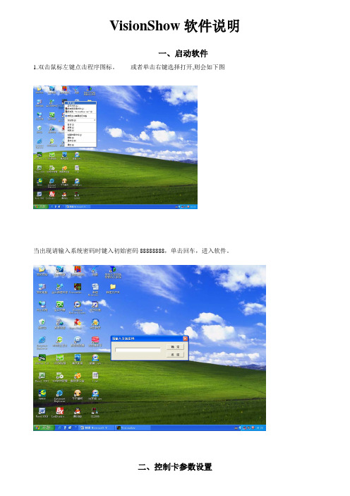
VisionShow软件说明一、启动软件1.双击鼠标左键点击程序图标。
或者单击右键选择打开,则会如下图当出现请输入系统密码时键入初始密码88888888,单击回车,进入软件。
步骤1:在菜单栏选择系统设置控制卡设置,输入系统密码键入初始密码88888888单击回车。
系统设置控制卡设置步骤2:进入控制卡设置界面,单击建立通讯与显示屏控制板建立通信。
备注:每次要输入新的数据都要进行建立通讯建立通讯界面上出现读取控制卡参数正常控制卡地址=00 说明计算机与控制卡连接正常步骤3:参数设置1、基本参数设置高度、宽度、通讯方式、串口号、IP地址高度:LED显示屏纵向点数宽度:LED显示屏横向点数通讯方式:串口通讯或是网络通讯串口号:串口通讯时,串口的选择。
IP地址:网络通讯时,设置IP地址2、扫描输出参数设置单击扫描输出参数(1)设置控制信号特性极性相反选择不正确时为黑字黄底色使能相反选择不正确时屏幕非常的暗逆向扫描选择不正确时字是显示镜像行取反选择不正确时字上下相反红绿反色选择不正确时发红时出绿字根据显示屏出现的现象选择!(2)设置扫描方式选择选择通讯方选择串口高度宽度IP地址的设置步骤4:将设置好的参数下载到主板,主板将按照新的参数运行。
扫描输出参数控制信号特性扫描方式选择单击设置参数:将设置好的参数下载到主板,主板将按照新的参数单击“是”控制板的基本设置参数完成单击“是”控制卡设置完成控制卡设置成功步骤1:单击一下控制卡,设置高度、宽度、通讯方式、宽度和高度的设置根据显示屏的横、纵点数来设置,设置后显示的黑屏就是显示屏的虚拟屏。
通讯方式的设置根据连接的方式是串口通讯还是网络通讯。
控制卡黑屏步骤2:单击显示页面设置,设置所发数据在显示屏上显示的时间。
时间以秒计算显示设置页面显示时间设置步骤3:添加数据,在红色框里选择添加自己所要添加的文本、word对象、图片、时钟。
选择添加数据样实例:通常我们使用的是“单行文本”出现如下图所示然后在单行文本上双击鼠标左键,如下图示在此处单击后增加“单行文本”在文字输入窗口中输入要发送到屏幕上的文字例如“欢迎光临依格电子”后再单击”确定”按钮如下图注意:一定要单击确定才能保存改变文字单击此处更改字此处更改数字改变字大小此处更改字的进入方式也可以用鼠标拖动文本框的边角上的白方块改变大小,点住左键来移动文本框的位置.总而言之:整个文本框的.字的颜色,大小,尺寸,位置, 显示方式(左滚动右滚动上翻页等)各种属性都在”对象属性的对应栏里更改.当更改完成后:我们再单击”显示页面1”单击这里把改好的内容发送到屏幕上(图1—1)在此处修改这个页面显示的时间设置页面的显示时间和显示速度:页面显示时间从0—999999999秒选择,单行文本字最多可以输入32768个汉字.显示速度一级最慢,八级最快.这样我们就完成了单行文本的输入,然后单击上面(图1-1)标注的位置的类似卫星的图标发送容到显示屏上.,单击”添加显示页”然后再重复上面的添加文本的操作,三.增加时间窗口比较重要的是”时间格式属性:这里可以选择: 年月日格式 ,但是只能选择一种,如果想要年单击此处增加时间窗口在此对象属性栏中修改日期时间的属性.和单行文本的修改类似,修改完成后把位置调整好,再发送到屏幕上再次单击增加,再排好位置月日,时分秒都显示的话,需要再增加一个”日期时间”然后排好两个日期时间窗口的位置,选好时间格式.再发送到显示屏上.。
CKVisionBuilder 软件使用手册

CKVisionBulider Ver3.0软件使用手册深圳市创科自动化控制技术有限公司版权所有2016-10-11首先感谢您选择使用CKVisionBuilder软件,此软件是深圳市创科自动化控制技术有限公司所开发的一款通用型智能机器视觉软件,是为了简化机器视觉系统的复杂度,降低工程人员的技术要求,不用编写任何代码,只需通过简单的将各个功能模块进行组合就可以完成一个复杂的机器视觉检测项目。
CKVisionBuilder软件包含有定位、测量、检测和识别等算法功能,还拥有强大的逻辑处理能力,可以同时处理多了检测任务,软件兼顾了简易性和灵活性,可以适应大多数项目的需求。
本手册详细介绍了CKVisionBuilder软件V3.0版本的使用和功能,以及各类工具的说明,使用前请仔细阅读此说明书。
第一章软件界面说明 (7)1.程序主界面 (7)1.1菜单栏 (7)1.2主工具栏 (8)1.3显示区域 (8)1.4流程栏 (9)1.5工具箱 (11)1.6数据栏 (11)1.7日志栏 (12)1.8快捷栏 (13)2.程序对话框 (13)2.1系统设置 (13)2.2密码设置 (14)2.3项目设置 (15)2.4流程设置 (16)2.5工具名称设置 (17)2.6用户界面编辑 (17)2.7图像控件设置 (19)2.8消息按钮控件设置 (19)2.9工具按钮控件设置 (20)2.10数值文本控件设置 (20)2.11状态文本控件设置 (21)2.12分组控件设置 (22)2.13数据分析 (23)2.14数据链接 (23)2.15算术表达式 (24)2.17显示图形页面 (26)第二章工具说明 (28)1.相机工具 (28)1.1DSCamera (28)2.图像处理 (29)2.1采集图像 (29)2.2存储图像 (30)2.3图像运算 (30)2.4彩色转灰 (31)2.5预先处理 (32)2.6颜色抽取 (33)3.标定校准 (33)3.1位置补正 (33)3.2坐标系 (34)3.3测量标定 (35)3.4对应点标定 (36)3.5图像矫正 (36)4.检测识别 (36)4.1像素统计 (36)4.2亮度检测 (37)4.3图像对比 (37)4.4BLOB分析 (40)4.5灰度匹配 (43)4.6形状匹配 (45)4.7检测边缘 (48)4.8检测间距 (50)4.9直线测量 (52)4.11字符集合 (56)4.12字符读取 (57)4.13读取条码 (58)4.14读取二维码 (59)4.15颜色监测 (60)4.16颜色识别 (61)5.几何测量 (62)5.1点到点 (62)5.2点到线 (63)5.3线到线 (64)5.4线到圆 (65)6.文件通讯 (67)6.1串行口 (67)6.2以太网 (67)6.3接收文本 (68)6.4发送文本 (69)6.5接收数据 (69)6.6发送数据 (70)6.7Modbus读 (71)6.8Modbus写 (72)6.9播放声音 (74)7.逻辑控制 (74)7.1等待延迟 (74)7.2条件分支 (75)7.3选择分支 (75)7.4循环工具 (76)7.5停止循环 (77)7.6执行流程 (77)7.8数据入队 (78)7.9数据出队 (79)7.10清空队列 (79)8.系统工具 (80)8.1更新画面 (80)8.2计算时间 (80)8.3用户变量 (80)8.4计算变量 (81)8.5设置变量 (82)8.6数据记录 (83)8.7清除记录 (84)8.8数值显示 (85)8.9数据判断 (86)8.10系统时间 (87)8.11生成文本 (88)8.12分解文本 (88)8.13比较文本 (89)9.三维测量 (90)9.13D扫描 (90)9.23D存储 (91)9.33D视图 (92)9.43D高度 (93)9.53D平面 (93)第一章软件界面说明1.程序主界面CKVisionBuilder 软件主界面如下图。
GBuilder操作手册
MGBuilder用户操作手册Rev. 2.1上海麦杰科技有限责任公司Shanghai Magus Technology Co., Ltd.2004年12月1.1 概述 (4)1.2 内容介绍 (4)2 MGBuilder配置及使用说明 (5)2.1内容介绍 (5)2.2 配置MGBuilder的使用环境 (5)2.2.1 Windows系统 (5)2.2.2 Unix及Linux系统 (5)2.3 MGBuilder的目录及文件结构 (6)2.4 MGBuilder功能概述 (6)2.5 启动MGBuilder (7)2.6 使用MGBuilder (7)2.6.1文件菜单 (7)2.6.2 编辑菜单 (8)2.6.3 查看菜单 (8)3 绘制及编辑图形元素 (10)3.1内容介绍 (10)3.2 线、多线 (10)3.2.1 线、多线的绘制 (10)3.2.2 线、多线的编辑 (10)3.3 矩形 (11)3.3.1 矩形的绘制 (11)3.3.2 矩形的编辑 (11)3.4 多边型 (11)3.4.1 多边形的绘制 (11)3.4.2 多边形的编辑 (11)3.5 椭圆 (11)3.5.1 椭圆的绘制 (11)3.5.2 椭圆的编辑 (12)3.6 圆弧 (12)3.6.1 圆弧的绘制 (12)3.6.2 圆弧的编辑 (12)3.7 文本 (12)3.7.1 文本的绘制 (12)3.7.2 文本的编辑 (13)3.8 采集点 (13)3.8.1 采集点的绘制 (13)3.8.2 采集点的编辑 (14)3.9 按钮 (14)3.9.1 按钮的绘制 (14)3.9.2 按钮的编辑 (15)3.10 时间 (15)3.10.1 时间的绘制 (15)3.10.2 时间的编辑 (15)4.1 内容介绍 (16)4.2 插入图像 (16)4.3 插入棒状图 (17)4.5 插入趋势 (17)5 图库的使用 (18)5.1内容介绍 (18)5.2插入图库元素 (18)5.3 添加图库对象 (19)6 设置图形属性 (20)6.1 内容介绍 (20)6.2 设置对象的颜色和填充方式 (20)6.3 设置对象的线型和线宽 (23)6.4 设置字体 (23)6.5 设置事件 (23)6.5 设置事件 (24)6.6 设置图形属性 (24)7 图形工具的使用 (25)7.1 内容介绍 (25)7.2 图形镜像 (25)7.2.1 左右镜像 (25)7.2.2 上下镜像 (25)7.3 旋转 (26)7.3.1 顺转90度 (26)7.3.2 逆转90度 (26)7.4 对齐 (26)7.4.1 左对齐 (26)7.4.2右对齐 (26)7.4.3上对齐 (27)7.4.4下对齐 (27)7.4.5 垂直对齐 (27)7.4.6 水平对齐 (27)7.5 组合 (28)7.5.1 组合 (28)7.5.2 取消组合 (28)8 使用帮助 (29)附录A MGBuilder快捷键速查 (30)附录B DSP文件格式 (31)附录C 使用中可能遇到的问题 (38)1 简介1.1 概述MGBuilder组态工具是专门为自动控制、控制系统仿真而设计的图形化组态工具,它具有图形编辑功能及动态定义功能,用户使用它可以很方便地绘制和仿真各种控制系统的过程图形,同时与图形浏览工具MGViewer配合使用,无需再进行复杂的二次编程,就可以实现各种控制的界面仿真工作,大大减少了为了追求仿真系统的形似所花费的时间,加快仿真系统的开发进度。
CKVisionBuilder软件案例教程

CKVisionBulider Ver3.0软件案例教程深圳市创科自动化控制技术有限公司版权所有2017-5-25诚挚感谢您使用创科CKVisionBuilder软件!迄今为止,中国正在成为世界机器视觉发展最为活跃的地区之一,应用范围宽广,涵盖了工业、农业、航天、交通、科研等国民经济的各个行业。
其重要原因是中国已经成为了全球制造业的加工中心,高要求的零部件加工及其相应的先进生产线,使很多具有国际先进水平的机器视觉系统和应用经验进入了中国,我公司力求打造国内一流水准的智能机器视觉软件。
CKVisionBuilder软件是深圳市创科自动化控制技术有限公司所开发的一款通用型智能机器视觉软件,软件易学易用,能够迅速实现视觉方案,及时响应客户,也能迅速进行软件的二次开发,完成项目的代码编写,提供方便的调试功能以及个性化设计,以便快速实现项目的验收。
您的选择将会是我们莫大的荣幸!抓紧时间,行动起来,学习创科CKVisionBuilder软件!本教程是关于CKVisionBuilder软件Ver3.0版本的案例详细介绍,使用前请配合说明书一起阅读。
目录第一章软件安装说明 (9)1.软件安装环境说明 (9)2.使用相机前注意事项 (9)3.软件使用说明 (9)4.软件自主界面设置 (10)第二章软件界面说明 (11)1.程序主界面 (11)1.1 菜单栏 (12)1.2 主工具栏 (12)1.3 流程栏 (12)1.4 数据栏 (13)1.5 日志栏 (14)2.程序对话框 (14)2.1 用户界面编辑 (14)2.1.1 用户界面编辑示例 (15)第三章工具说明 (18)1.添加软件工具 (18)1.1 添加步骤 (18)2.相机工具 (19)2.1 DSCamera (19)2.2 JAICamera (20)2.2.1 相机工具示例 (20)2.3 AVTGigeCamera (23)3.图像处理 (24)3.1 采集图像 (24)3.2 存储图像 (25)3.2.1 存储图像示例 (25)3.3 图像运算 (27)3.4 彩色转灰 (27)3.5 预先处理 (28)3.5.1 预先处理示例 (28)3.6 颜色抽取 (33)3.7 图像合并 (34)3.7.1 图像合并示例 (34)4.标定校准 (38)4.1 位置补正 (38)4.2 图像补正 (39)4.2.1 图像补正示例 (39)4.3 坐标系 (40)4.4 测量标定 (40)4.4.1 测量标定示例 (41)4.5 对应点标定 (44)4.6 图像标定 (44)4.6.1 图像标定示例 (44)5.检测识别 (46)5.1 像素统计 (46)5.1.1 参数设置 (47)5.2 亮度检测 (47)5.2.1 参数设置 (48)5.3 图像对比 (48)5.3.1 图像对比示例 (48)5.4 BLOB分析 (52)5.4.1 参数设置 (52)5.4.2 高级参数设置 (53)5.4.3 数据结果 (54)5.5 灰度匹配 (54)5.5.1 参数设置 (55)5.5.2 数据结果 (56)5.6 形状匹配 (56)5.6.1 形状匹配示例 (56)5.7 检测边缘 (60)5.7.1 参数设置 (61)5.7.2 数据结果 (62)5.8 检测间距 (62)5.8.1 检测间距示例 (62)5.9 检测宽窄 (66)5.9.1 检测宽窄示例 (66)5.10 轮廓缺陷 (67)5.10.1 轮廓缺陷示例 (67)5.11 直线测量 (69)5.11.1 参数设置 (69)5.11.2 数据结果 (70)5.12 圆形测量 (70)5.12.1 圆形测量示例 (70)5.13 字符集合 (73)5.14 字符读取 (74)5.14.1 字符读取示例 (74)5.15 字符验证 (78)5.15.1 字符验证示例 (78)5.16 读取条码 (80)5.16.1 条码读取示例 (81)5.17 读取DM码 (83)5.17.1 读取DM码示例 (83)5.18 读取QR码 (86)5.18.1 读取QR码示例 (86)5.19 颜色监测 (88)5.19.1 参数设置 (89)5.20 颜色识别 (89)5.20.1 参数设置 (90)6.几何测量 (90)6.1 点到点 (90)6.1.1 点到点示例 (91)6.2 点到线 (95)6.2.1 点到线示例 (95)6.3 线到线 (97)6.3.1 线到线示例 (98)6.4 线到圆 (101)6.4.1 线到圆示例 (101)6.5 拟合线 (103)6.5.1 拟合线示例 (104)6.6 拟合圆 (105)6.6.1 拟合圆示例 (106)7.文件通讯 (108)7.1 串行口 (108)7.1.1 串口示例 (108)7.2 以太网 (113)7.2.1 以太网示例 (113)7.3 接收文本 (119)7.4 发送文本 (120)7.5 接收数据 (120)7.6 发送数据 (122)7.7 Modbus读 (122)7.7.1 参数设置 (123)7.7.2 数据列表 (124)7.8 Modbus写 (124)7.8.1 参数设置 (125)7.8.2 数据列表 (126)7.9 播放声音 (126)8.逻辑控制 (126)8.1 等待延迟 (126)8.2 条件分支 (127)8.3 选择分支 (127)8.4 循环工具 (128)8.5 停止循环 (128)8.5.1 分支循环示例 (129)8.6 执行流程 (135)8.7 并行流程 (135)8.7.1 多流程和条件分支示例 (136)8.8 数据入队 (145)8.9 数据出队 (146)8.10 清空队列 (146)9.系统工具 (147)9.1 更新画面 (147)9.2 计算时间 (147)9.3 用户变量 (147)9.4 计算变量 (148)9.4.1 计算变量示例 (148)9.5 设置变量 (151)9.6 数据记录 (152)9.7 清除记录 (153)9.8 数值显示 (153)9.8.1 数值显示示例 (153)9.9 数据判断 (154)9.10 系统时间 (155)9.11 生成文本 (156)9.12 分解文本 (156)9.13 比较文本 (157)9.13.1 文本工具示例 (158)9.14 3D扫描示例 (162)第一章软件安装说明1.软件安装环境说明该软件仅支持Windows系统,建议使用WIN XP,WIN 7,WIN 8系统;同时建议使用32位系统(很多相机还没有64位驱动,只有32位驱动),Linux系统、Mac OS X系统、FreeBSD系统不支持;公司提供一款免费试用90天的builder软件,试用期到期后,只有重新安装加密狗才能继续使用;软件连接Gige(千兆网口)相机前,需要设置;打开电脑设备管理器,将网络适配器中的网卡属性打开,将高级选项中的巨帧右侧从“禁用”状态修改为“9014”字节或者9KB。
CkvsBuilder使用手册

CkvsBulider 软件软件使用手册使用手册深圳深圳市市创科自动化控制技术有限公司版权所有 更新日期更新日期::2013-12-12CkvsBuilder软件是深圳市创科自动化控制技术有限公司所开发的一款通用机器视觉软件,该软件是为了简化机器视觉系统的复杂度,降低开发人员的技术要求,不用编写任何代码,只需简单的将各个功能模块进行组合就可以完成一个复杂的机器视觉检测项目,为开发人员缩短了开发周期,为客户赢得了时间。
本手册详细介绍了CkvsBuilder软件的功能及应用,使用前请仔细阅读此说明书。
1. 界面说明 (5)1.1. 主界面 (5)1.2. 主工具栏 (5)1.3. 编辑工具栏 (6)1.4. 显示区域 (6)1.5. 流程编辑栏 (6)1.6. 工具箱栏 (7)1.7. 视图设置 (7)1.8. 密码设置 (8)2. 操作说明 (9)2.1. 新建项目 (9)2.2. 编辑流程 (9)2.3. 编辑工具 (9)2.4. 数据链接 (10)2.5. 最终状态设定 (10)3. 工具说明 (12)3.1. 基本设置 (12)3.2. 通用相机 (13)3.3. 采集图像 (13)3.4. 存储图像 (14)3.5. 彩色转灰 (15)3.6. 预先处理 (15)3.7. 单位转换 (16)3.8. 坐标系统 (17)3.9. 面积检测 (18)3.10. 亮度检测 (18)3.11. 图像对比 (19)3.12. BLOB分析 (20)3.13. 灰度匹配 (23)3.14. 形状匹配 (24)3.15. 检测边缘 (27)3.16. 检测间距 (29)3.17. 直线测量 (31)3.18. 圆形测量 (32)3.19. 计算距离 (34)3.20. 计算角度 (35)3.21. 计算位置 (35)3.22. 合成直线 (36)3.23. 串行口 (37)3.24. 以太网 (38)3.25. 状态输入 (39)3.26. 状态输出 (39)3.27. 接收数据 (40)3.28. 发送数据 (41)3.29. 数据显示 (42)3.30. 计算器 (43)3.31. 数据判断 (46)3.32. 条件输出 (46)3.33. 条件跳转 (47)3.34. 循环工具 (48)3.35. 如果工具 (49)3.36. 分支工具 (49)3.37. 执行流程 (50)3.38. 等待延迟 (50)3.39. 更新视图 (51)说明1. 界面说明1.1. 主界面图1-1 主界面1.2. 主工具栏新建一个项目工程。
SICK SLS Visualization Software 快速入门指南说明书
Safety Laser Scanner Visualization SoftwareFor microScan3 and outdoorScan3Quickstart GuideQuickstart GuideInhalt1. Display scanner data in 7 steps (3)Step 1 – Connect Scanner (3)Step 1.1 – Power Supply (3)Step 1.2 – Ethernet Cable (3)Step 2 – Set up Ethernet Connection (4)Step 2.1 – Read out IP address using Safety Designer (4)Step 2.2 – Read out IP address on display of safety laser scanner (4)Step 3 – Download Software (4)Step 4 – Preparing SLS Visualization Software (5)Step 4.1 –Edit “executable” file to correct IP address (5)Step 4.2 – Replace IP address (5)Step 4.3 – Save file (6)Step 5 – Preparing the computer for the network connection. (7)Step 6 – Open the SLS Visualization Software (9)Step 7 – SLS Visualization Software is displayed (9)2. Using the SLS Visualization Software on WinCC – Overview (10)WinCC Professional (TIA Portal) (10)WinCC Advanced (TIA Portal) (11)Quickstart Guide – Safety Laser Scanner Visualization Software This document describes the steps to run the SLS Visualization Software for microScan3 and outdoorScan3.Pre-requisites:Windows PC (Win XP and up).o Note 1: The SLS Visualization Software does not run on Windows CE.W indows CE has reached End of Life Support in 2018; therefore SICK cannotprovide the SLS Visualization Software for Windows CE.o Note 2: Many SIEMENS HMI's using TIA Portal are based on Windows / WinCC → therefore many SIEMENS HMI's are supported.Supported devicesAll microScan3 devices - except all microScan3 Core I/O versionsOnly outdoorScan3 Pro EtherNet IP1. Display scanner data in 7 stepsStep 1 – Connect ScannerFirst, connect the safety laser scanner to the HMI or computer on which the SLS Visualization Software is used.Step 1.1 – Power SupplyConnect scanner to power supply with 24V. Find appropriate cables on .As an example, the following cable can be used for power connection for microScan3 ProPROFINET:Step 1.2 – Ethernet CableConnect safety laser scanner to HMI or computer using an Ethernet cable. Find appropriate cables on . As an example following cable can be used for microScan3 Pro PROFINET :Step 2 – Set up Ethernet ConnectionThe next step is to set up the Ethernet Connection. In order to do this the IP address of the safety laser scanner needs to be known. There are two simple ways to read it out.Step 2.1 – Read out IP address using Safety DesignerOpen Safety Designer, connect to device (e.g. by using USB cable) and see address on pageaddressing.Step 2.2 – Read out IP address on display of safety laser scannerUse the Buttons on the Safety Laser Scanner. (Device Info Network IP address)Step 3 – Download SoftwareClick link to download the SLS Visualization Software:- SICK Internal: Download here:https:///pages/viewpageattachments.action?pageId=393349683&preview=/393349683/393349693/microScan3-VISU-Diagnostics_V1-0.rar- SICK External: receive Secureshare Link by your SICK Contact.When the download is finished open the ZIP file as follows:Unpack ZIP file to afolder of choiceStep 4 – Preparing SLS Visualization SoftwareWhen the file is unzipped, following files should be included:Step 4.1 –Edit “executable” file to correct IP addressThe IP address that is programmed must be edited before starting the THE SLS VISUALIZATION SOFTWARE.Step 4.2 – Replace IP addressA window will open in which the specified IP address must be exchanged by the address of the safety laserscanner. If you do not have this IP address then go back to “Step 2”.Right click on the file "Execute_192_168_1_5.bat " allows editing of the file.Replace the pre-programmed IP address with the actual IP address of the scanner.Step 4.3 – Save fileOnce the IP address is set correctly safe the executable with its new name. The name should include the actual IP addressStep 5 – Preparing the computer for the network connection.Using Windows computers the connection may have to set in the Control panel. See steps below.Open Network andSharing Center.Go to …Ethernet“Go to “Properties”Go to …Internetprotocol, Version 4 (TCP/IPv4)“Enter the IP address andsubnet mask. Subnet mask is the same asthe scanner.Note that this is the IP address ofthe HMI VISU, not of thescanner. Thus: Same subnet, nutdifferent IP address, however insame range. Confirm …OK“.Step 6 – Open the SLS Visualization SoftwareOpen the bat file.Step 7 – SLS Visualization Software is displayedOpen the bat file that was created previously with the actual IP address in itThe VISU tool will open and should automatically connect to the safety laser scanner.2. Using the SLS Visualization Software on WinCC – OverviewWinCC (TIA Portal) is available in different variants WinCC Basic, WinCC Comfort, WinCC Advanced and WinCC Professional. In addition, there are the two runtime systems WinCC Runtime Advanced and WinCC Runtime Professional. The difference between the variants lies primarily in the configurable devices.WinCC Professional (TIA Portal)With WinCC Professional the THE SOFTWARE DIAG tool can be opened with an exe file via a c script. To do this the following code must be written into the script.WinCC Advanced (TIA Portal)To start the HMI VISU DIAG tool the following software is needed on WinCC Advanced: The tool can then be implemented into the WinCC advanced software.The tool can now be displayed via WinCC Advanced.The …diag2“-Button, will start the defined eventHere you can choose at which event an actionshould be executed. Under …Program name“ youhave to link the tool you want to open.。
VISION中文的使用说明
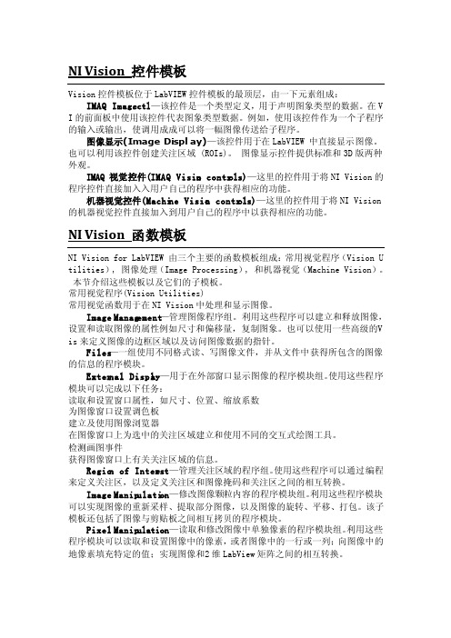
NI Vision控件模板Vision控件模板位于LabV IEW控件模板的最顶层,由一下元素组成:IMAQ Image.ctl—该控件是一个类型定义,用于声明图象类型的数据。
在V I的前面板中使用该控件代表图象类型数据。
例如,使用该控件作为一个子程序的输入或输出,使调用成成可以将一幅图像传送给子程序。
图像显示(ImageDispla y)—该控件用于在LabVI EW 中直接显示图像。
也可以利用该控件创建关注区域 (ROIs)。
图像显示控件提供标准和3D版两种外观。
IMAQ 视觉控件(IMAQ Vision contro ls)—这里的控件用于将NIVision的程序控件直接加入入用户自己的程序中获得相应的功能。
机器视觉控件(Machin e Vision contro ls)—这里的控件用于将NIVision 的机器视觉控件直接加入到用户自己的程序中以获得相应的功能。
NI Vision函数模板NI Vision for LabVIE W 由三个主要的函数模板组成:常用视觉程序(Vision U tilit ies), 图像处理(ImageProces sing), 和机器视觉(Machin e Vision)。
本节介绍这些模板以及它们的子模板。
常用视觉程序(Vision Utilit ies)常用视觉函数用于在NI Vision中处理和显示图像。
ImageManage ment—管理图像程序组。
利用这些程序可以建立和释放图像,设置和读取图像的属性例如尺寸和偏移量,复制图象。
也可以使用一些高级的V is来定义图像的边框区域以及访问图像数据的指针。
Files—一组使用不同格式读、写图像文件,并从文件中获得所包含的图像的信息的程序模块。
NI Vision Builder AI入门教程 第七章 视觉助手3 灰度选板
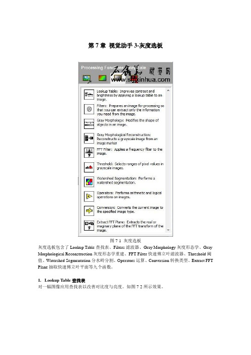
第7章视觉助手3-灰度选板图7-1 灰度选板灰度选板包含了Lookup Table查找表、Filters滤波器、Gray Morphology灰度形态学、Gray Morphological Reconstruction灰度形态学重建、FFT Filter快速傅立叶滤波器、Threshold阈值、Watershed Segmentation分水岭分割、Operators运算、Conversion转换类型、Extract FFT Plane抽取快速傅立叶平面等九个函数。
1. Lookup Table查找表对一幅图像应用查找表以改善对比度与亮度。
如图7-2所示效果。
图7-2 查找表在查找表列表框中,有以下功能可用:∙Image Source—原始图像∙Equalize—均衡图像,增强动态强度由指定的灰度级间隔在整个灰度级上分配。
此函数再分配像素值以便提供一个线性的累积直方图。
∙Reverse—反转图像,反转像素值,显示原始图像的底片。
∙Logarithmic—对图像应用对数变换,以增强暗区的亮度与对比度。
∙Exponential—对图像应用指数变换,以减弱亮区亮度,提高亮区对比度。
∙Square—平方,减少暗区对比度。
类似于指数但是有更平滑的效果。
∙Square Root—平方根,减少亮区的对比度。
类似于对数但是有更平滑的效果。
∙Power X—X次方,减少暗区对比度。
∙Power 1/X—X次根,减少亮区对比度。
X:幂运算的指数,默认值为1.5。
2. Filters滤波器这里的滤波器与VBAI增强图像选板中的滤波器作用、功能、算法基本类似,请参看前面第三章中关于VBAI滤波器的介绍。
图7-3 VBAI视觉助手滤波器3. Gray Morphology灰度形态学更改图像中目标的形状。
点击函数其配置界面如图7-4所示。
图7-4 灰度形态学灰度形态学操作∙Image Source:原始图像∙Dilate:灰度膨胀操作。
SICK Vision Suite User Manual 1.1说明书

SICK Vision Suite User Manual 1.1Contents1 Preface (3)2 Notes on usage (4)3 Introduction (5)4 Basic terms (6)4.1 GenICam (6)4.2 GenAPI (6)4.3 SFNC (6)4.4 GenTL (7)4.5 GenTL modules (7)4.6 GenTL SFNC (8)5 Terms and abbreviations (9)6 SICK Vision Suite (10)7 Components (11)8 Applications in SICK Vision Suite (12)8.1 SICK Vision Cockpit (12)8.2 Command line tools (12)8.2.1 Configuring a camera (13)8.2.2 Configuring network settings (13)8.2.3 Updating the camera firmware (14)8.3 Executable samples (15)1 PrefaceIntroductionSICK AG has taken every possible care in preparing this manual. We however assume no liability for the content, completeness or quality of the information contained therein. The content of this manual is regularly updated and adapted to reflect the current status of the software. We furthermore do not guarantee that this product will function without errors, even if the stated specifications are adhered to.Under no circumstances can we guarantee that a particular objective can be achieved with the purchase of this product.Insofar as permitted under statutory regulations, we assume no liability for direct damage, indirect damage or damages suffered by third parties resulting from the purchase of this product. In no event shall any liability exceed the purchase price of the product.Please note that the content of this manual is neither part of any previous or existing agreement, promise, representation or legal relationship, nor an alteration or amendment thereof. All obligations of SICK AG result from the respective contract of sale, which also includes the complete and exclusively applicable warranty regulations. These contractual warranty regulations are neither extended nor limited by the information contained in this manual. Should you require further information on this product, or encounter specific problems that are not discussed in sufficient detail in the manual, please contact your local dealer or system installer.TrademarksMicrosoft and Windows are trademarks or registered trademarks of Microsoft Corporation. All other products or company names mentioned in this manual are used solely for purposes of identification or description and may be trademarks or registered trademarks of the respective owners.Copyright© SICK AG. All rights reserved. This manual may not be reproduced, transmitted or translated to another language, either as a whole or in parts, without the prior written permission of SICK AG.Status: April 2020ContactVisit our web site where you will find all the latest information about our software and hardware products.Address SICK AGErwin-Sick-Str. 1D-79183 Waldkirch, GermanyT+49 7681 202-0E*************W 2 Notes on usageThis symbol indicates hints with useful information for better understanding and usingfeatures and functions.This symbol indicates important warnings for product safety to prevent damage.This symbol indicates important warnings for personal safety to prevent injury.3 IntroductionSICK Vision Suite is a comprehensive software package from SICK AG that can be used with GenICam-compliant industrial cameras. SICK Vision Suite provides all necessary tools to open cameras in an application with graphical user interface, to parametrize them, to capture images, etc. or to program your own application.Fig. 1: SICK Vision Suite4 Basic termsFig. 2: GenICam and Vision standards·GenICam·GenAPI·SFNC·GenTL·GenTL modules·GenTL SFNC4.1 GenICamGenICam (Generic Interface for Cameras) is a generic programming interface for cameras in industrial image processing. The GenICam standard is supervised by EMVA (European Machine Vision Association). The current version of the GenICam definition and a reference implementation of the GenAPI are available on the web site . There you will also find further information about the structure of GenICam standard.4.2 GenAPIWithin the GenICam standard, the GenAPI (Generic Application Programming Interface) is used for camera configuration, camera access and camera control. The GenAPI reads the description files (camera XML) of the GenICam-compliant cameras describing which features the cameras support.4.3 SFNCThe SFNC (Standard Features Naming Convention) defines camera features and properties and their names that can be included in the camera XML. The camera features are implemented in the firmware, i.e. the camera is not dependent on drivers installed on the PC. The features are grouped under different nodes in a tree and follow a well-defined access scheme. Each feature is clearly described:·what type it is (integer, floating point, string, etc.)·what the feature can do (feature description)·which are the minimum and maximum values·which discrete parameters exist for some features ("enumeration")·which feature affects other featuresExample: adjusting the exposure time, for example, changes the maximum possible frame rate. In thecamera XML it is specified that the frame rate should be read out again in case of an exposure time change.·etc.This exact description allows to dynamically read and display the current state of the camera and its features at runtime. Normally, this is done in an application via a graphical tree view. Since each feature also specifies which value is below, the control elements can be chosen accordingly in the application and the tree can be built dynamically. This behavior is referred to as "generic".4.4 GenTLThe GenTL (Generic Transport Layer) is a layer that is responsible for the transport of the camera data. The GenTL (or transport layer) converts the commands of the GenAPI and/or the application (consumer) into commands for the camera driver. Furthermore, the GenTL is responsible for submitting the camera XML to the GenAPI.It is differentiated between a GenTL Producer and a GenTL Consumer:·The GenTL Producer is the software that accesses the camera and provides the image data for an application. A GenTL Producer is provided as a platform-dependent, dynamically loadable library. The file extension of this library is *.cti (Common Transport Interface).·The GenTL Consumer is a software e.g. an application that receives the data.4.5 GenTL modulesThe GenTL consists of different modules, which are represented in a hierarchical tree structure with the system module as root.Fig. 3: GenTL modules·System moduleThe system module is called once for each GenTL. It is the entry point for a GenTL Producer from which the subsequent modules are called.·Interface moduleAn interface module represents a specific hardware interface, e.g. a network card for an Ethernet-based GenTL.·Device moduleYou can access multiple devices through an interface. These are the actually available devices e.g. cameras. A device can only be opened once with full access control.·Stream moduleTo capture images from a camera, for example, an image data stream has to be initialized in that device. The GenTL can capture multiple streams per device if the device supports it.·Buffer moduleThe buffers are the image memories into which the captured images are written. The image memories can be allocated either by the GenTL Consumer or GenTL Producer.4.6 GenTL SFNCThe GenTL standard defines a set of feature names and their definitions. The GenAPI module is used to access these features. The GenTL SFNC (GenTL Standard Feature Naming Convention) standardizes the used features in order to separate the GenTL standard as far as possible from the definition of specific features.The GenTL SFNC does not replace the features that are defined in the regular GenICam SFNC, but enhances them by explicitly covering only the features of the GenTL producer itself.7 ComponentsSICK Vision Suite provides all necessary libraries and software interfaces for application developers and thus forms a complete SDK (software development kit). SICK Vision Suite is based on the module hierarchy defined by the standards (GenICam, GenTL). At the same time, the interface is considerably easier to operate without limiting the functionality of the standardized interface. SICK Vision Suite can be used with the C#, C+ +, and C programming languages. The use of C# or C++ is recommended.In addition, SICK Vision Suite combines GUI-based applications and practical command line tools. The components in SICK Vision Suite are:SICK Vision APIApplication programming interface that provides convenient access to all associated libraries (GenAPI, GenTL, etc.). The core task of the SICK Vision API is the communication with the camera, the camera parametrization and the transfer of the image data to the computer.The SICK Vision API is described in a separate documentation.SICK LibIMGThis is a library for high-performance image processing on the computer (Image Processing Library). The SICK LibIMG can be used, for example, to convert camera image that were captured via the SICK Vision API from raw bayer format into color (debayering).The SICK LibIMG is described in a separate documentation.Samples (source code)All samples are delivered open as source code in SICK Vision Suite. Thus, the samples can also be used as starting point for your own programming.Under Windows, the samples are also included as executable files (binaries) and can be executed directly. Transport layerThe transport layers are responsible for transferring the camera data to the user application. It is a low-level hardware interface for translating API commands into camera understandable commands.·SICK GenICam Producer (GEVK)GenTL Producer (required for image processing programs based on the GenICam interface) including a kernel driver to improve Ethernet performance. The use of this GenTL Producer is recommended.·SICK GenICam Producer (GEV)GenTL Producer (required for image processing programs based on the GenICam interface) This GenTL Producer can be installed as an alternative to "SICK GenICam Producer (GEVK)" if it is not possible to install a kernel driver on the system.SICK Vision CockpitGraphical user interface for camera parametrization and live display of images. See SICK Vision Cockpit ToolsCollection of useful command line programs, e.g. to update the camera firmware. See Command line tools Samples (binaries)Collection of sample programs that are offered both in source code and as executable files and can therefore be used directly. See Executable samples8 Applications in SICK Vision Suite·SICK Vision Cockpit·Command line tools·Executable samples8.1 SICK Vision CockpitThe SICK Vision Cockpit provides you with a graphical interface to quickly and easily evaluate cameras without programming a line of code. In addition to display all camera parameters in a GenICam-typical tree view, the SICK Vision Cockpit provides you with a lot of practical image information and dialog-based settings.1.Menu and symbol bar, e.g. open camera, start/stop image acquisition or change camera settings2.Camera list with the available GenTL modules (transport layers, interfaces, cameras)In the camera list, for example, use the context menu to open the dialog for configuring the IP address of a GigE Vision camera.3.Camera properties in the tree views with filtering by beginner, expert, guru and search term4.Camera image with information display e.g. of the captured frames, frame rate (fps) and size (height andwidth in pixels)Fig. 4: SICK Vision Cockpit8.2 Command line toolsUse the handy command line tools e.g. to automatically configure several cameras.The sick_cmdtools shortcut gives you quick access to the command line tools and the SICK Vision Cockpit.·Configuring a camera·Configuring network settings·Updating the camera firmware8.2.1 Configuring a camerasick_devicecommand provides you with information about all available camera settings via the GenICam interface and allows you to configure the camera directly. This tool is intended for expert users.You can list further options with:sick_devicecommand --helpFig. 5: sick_devicecommand8.2.2 Configuring network settingsWith sick_ipconfig you can query and configure the network settings of the cameras.You can list further options with:sick_ipconfig --helpWith a special, interactive mode, you can configure the IP address easily with dialog guidance:sick_ipconfig --interactiveFig. 6: sick_ipconfigYou can also configure the IP address using the graphical interface of SICK Vision Cockpit.8.2.3 Updating the camera firmwareUse the firmware update tool sick_deviceupdate to transfer the firmware update to the camera using the GUFfile. The command line tool allows you to choose the camera explicitly for the update.(GUF file version >= 1.5).1.Make sure that GigE Vision cameras have a valid IP address.2.Open the command line tool in the GUF directory.3.List all available cameras with:sick_deviceupdate --list-all4.You can also list all available cameras with their current firmware version:sick_deviceupdate --list-device-versions5.Select a camera based on the last digits of its serial number and start the update, e.g.sick_deviceupdate -s *7362 -U --guf c:\GUF\<model-name>-C.guf6.Confirm the update with "y".A firmware update can take several seconds. Wait until it is finished.You can list further options with:sick_deviceupdate --helpFig. 7: sick_deviceupdate8.3 Executable samplesC++C#- A -Abbreviations 9- C -Cameraconfigure 13parameter 13 Command line 12- D -DeviceTree 15- F -Firmwareupdate 14- G -GenApi 6GenICam 6GenTLbuffer 7consumer 7device 7GenTL Consumer 6GenTL Producer 6interface 7producer 7stream 7system 7GenTL SFNC 6, 8 GetFirstPixel 15- I -IP addressconfigure 13set 13- L -LegoTrigger 15- N -Network 13- O -OpenCamera 15 OpenCameraBySerNo 15 OpenCameraSelectCti 15- S -Sample 11, 15SFNC 6SICK LibIMG 11SICK Vision API 11 SICK Vision Cockpit 11 overview 12SICK Vision Suite 5, 10 application 12part 11 SimpleLiveQml 15 SimpleLiveQtWidgets 15- T -Toolcommand line 12 Transport Layer 11- U -Updatefirmware 14- W -WalkThrough 15Detailed addresses and further locations at AustraliaPhone +61 (3) 9457 06001800 33 48 02 – tollfreeE-Mail **************.au AustriaPhone +43 (0) 2236 62288-0 ********************Belgium/LuxembourgPhone +32 (0) 2 466 55 66 ******************BrazilPhone +55 11 3215-4900 ************************.br CanadaPhone +1 905.771.1444 ************************Czech RepublicPhone +420 234 719 500 ******************ChilePhone +56 (2) 2274 7430 E-Mail **************ChinaPhone +86 20 2882 3600 E-Mail *******************.cn DenmarkPhone +45 45 82 64 00 ******************FinlandPhone +358-9-25 15 800 ******************FrancePhone +33 1 64 62 35 00 ******************GermanyPhone +49 (0) 2 11 53 010 ******************GreecePhone +30 210 6825100 E-Mail ***************.gr Hong KongPhone +852 2153 6300 E-Mail ************.hkHungaryPhone +36 1 371 2680 *************************IndiaPhone +91-22-6119 8900 *************************IsraelPhone +972 97110 11***************************ItalyPhone +39 02 27 43 41 ******************JapanPhone +81 3 5309 2112 *********************MalaysiaPhone +603-8080 7425 *************************MexicoPhone +52 (472) 748 9451 *********************NetherlandsPhone +31 (0) 30 229 25 44 ******************New ZealandPhone +64 9 415 04590800 222 278 – tollfreeE-Mail *************.nz NorwayPhone +47 67 81 50 00 ******************PolandPhone +48 22 539 41 00 ******************RomaniaPhone +40 356-17 11 20 E-Mail **************RussiaPhone +7 495 283 09 90 ******************SingaporePhone +65 6744 3732 ************************SlovakiaPhone +421 482 901 201 *********************SloveniaPhone +386 591 78849 ********************South AfricaPhone +27 10 060 0550****************************.za South KoreaPhone +82 2 786 6321/4 ************************SpainPhone +34 93 480 31 00 ******************SwedenPhone +46 10 110 10 00 ******************SwitzerlandPhone +41 41 619 29 39 *********************TaiwanPhone +886-2-2375-6288 ********************.tw ThailandPhone +66 2 645 0009 ************************TurkeyPhone +90 (216) 528 50 00 *******************.tr United Arab EmiratesPhone +971 (0) 4 88 65 878 *********************United KingdomPhone +44 (0)17278 31121 ******************.uk USAPhone +1 800.325.7425 *******************VietnamPhone +65 6744 3732 ************************SICK AG | Waldkirch | Germany | 8025622/0000/2020-04/e n。
康耐视相机软件手册说明书

features and operations, as well as imaging and acquisition controls. Firmware updates—ensure you are using to most up-to-date firmware for the camera to take advantage of improvements and fixes.Minimum System Requirements Gigabit Ethernet host adapter GigE Vision compatible camera Cognex VisionPro 5.0 or newer Installation and Configuration Cognex eBus Universal Pro Driver The Cognex eBus Universal Pro Driver is a GigE Vision filter driver that must be enabled in order to use GigE cameras in Cognex. This driver operates between the camera and the Microsoft built-in UDP stack to filter out GigE vision stream protocol (GVSP) packets. The CPU does not process all the packets, and therefore reduces CPU usage. Network Properties Menu Cognex GigE Vision Configuration Tool Ensure the camera is enumerated correctly. The host adapter and the camera must be on the same subnet.Users can use the tool to manually set the IP address and the subnet mask of the host adapter or the camera. Cognex GigE Vision Configuration Tool Understanding GigE Vision GigE Vision is a standard for camera control developed for Gigabit Ethernet cameras. All cameras supporting GigE Vision will interact the same way with software supporting GigE Vision such as VisionPro. FLIR GigE cameras such as Blackfly S, Blackfly, Flea3, Grasshopper3, and Grasshopper2 are GigE Vision compatible cameras that work seamlessly with GigE Vision software.Each camera attribute such as shutter time is controlled by a specific GigE Vision attribute. All GigE Vision software provides a Graphical User Interface (GUI) to control these GigE Vision attributes. The following sections will describe what these controls are in VisionPro and how each control is mapped to the respective GigE Vision attribute. packet size and packet delay, based on desired resolution and frame rate. Packet Size (GevSCPSPacketSize) Packet size influences the number of interrupts generated which affects CPU usage. The larger the packet size, the fewer the interrupts for the same amount of data.。
NI Vision Builder AI入门教程 第二章 配置界面
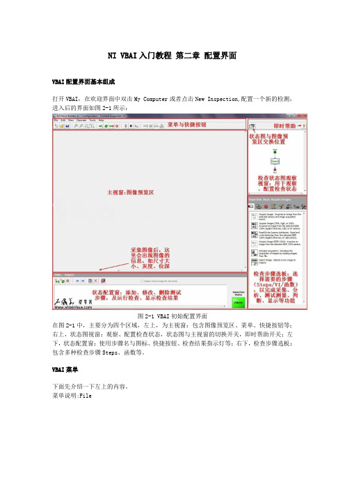
NI VBAI入门教程第二章配置界面VBAI配置界面基本组成打开VBAI,在欢迎界面中双击My Computer或者点击New Inspection,配置一个新的检测,进入后的界面如图2-1所示:图2-1 VBAI初始配置界面在图2-1中,主要分为四个区域,左上,为主视窗:包含图像预览区、菜单、快捷按钮等;右上,状态图视窗:观察、配置检查状态,状态图与主视窗的切换开关,即时帮助开关;左下,状态配置窗:使用步骤名与图标、快捷按钮、检查结果指示灯等;右下,检查步骤选板:包含多种检查步骤Steps、函数等。
VBAI菜单下面先介绍一下左上的内容。
菜单说明:File图2-2 菜单-File文件文件菜单从上到下依次是New新建、New from Template从模板新建、Open打开、Save保存、Save As另存为、Save As Template另存为模板、Save Image保存图片、Print Image 打印图片、Print Inspection打印检查、Inspection Properties检查属性、Switch to Inspection Interface切换到检查界面、Close关闭。
此菜单中的选项,主要用于VBAI脚本的保存、图片的保存、脚本的属性、切换界面等功能。
图2-3 菜单-Edit编辑编辑菜单从上到下依次为Edit Step编辑步骤、Cut剪切、Copy复制、Paste粘贴、Delete 删除。
本菜单中的内容,主要用于控制检查步骤。
图2-4 菜单-View查看查看菜单从上到下依次是Zoom In放大、Zoom Out缩小、Zoom 1:1原始大小、Zoom to Fit 适合视窗、Toggle Main Window View切换主视窗与状态图视窗、View Inspection State Diagram查看检查状态图、View Complete Inspection Setup查看完整检查设置(包含setup、cleanup)、View Custom Inspection Interface查看用户检查界面(需要配置用户界面后才能查看)。
dcckvisionplus编程语言
dcckvisionplus编程语言DCCKVisionPlus编程语言DCCKVisionPlus编程语言是一种功能强大且易于使用的高级编程语言。
它旨在为开发人员提供一种灵活的方式来创建复杂的视觉处理应用程序。
无论您是初学者还是经验丰富的程序员,DCCKVisionPlus编程语言都能满足您的需求。
在本文中,我将逐步介绍DCCKVisionPlus编程语言的主要特性和用法。
第一步:安装和设置要使用DCCKVisionPlus编程语言,您需要先安装它。
您可以从官方网站上下载编译器和开发工具包。
安装完成后,您可以按照说明进行设置和配置。
同时,您还需要了解一些关于计算机视觉和图像处理的基本概念。
第二步:编写您的第一个程序在DCCKVisionPlus编程语言中,您可以使用类似于其他高级编程语言的语法和结构来编写程序。
下面是一个简单的程序示例:pythonimage = load_image("example.jpg")gray_image = convert_to_gray(image)processed_image = apply_filter(gray_image, "blur")save_image(processed_image, "output.jpg")这个程序加载名为"example.jpg"的图像,将其转换为灰度图像,然后应用一个模糊滤波器。
最后,将处理后的图像保存为"output.jpg"。
第三步:了解DCCKVisionPlus的特性DCCKVisionPlus编程语言具有许多强大的特性,使其成为一个出色的选择来开发视觉处理应用程序。
以下是其中的一些特性:1. 图像加载和保存:您可以使用简单的命令来加载和保存图像,使您能够轻松地处理图像文件。
2. 图像处理工具:DCCKVisionPlus提供了许多内置的图像处理工具,如图像滤波、边缘检测和形态学操作等。
视觉定位软件VisionKit软件说明书

文件名称:视觉定位软件VisionKit使用说明书文件版本:中文简体版文件页数:共 42 页(含此页)编制:审核:标准化:批准:日期:大族激光科技产业集团股份有限公司视觉定位软件VisionKit使用说明书(版本:中文简体版)大族激光科技产业集团股份有限公司声明版权所有 ? 大族激光科技产业集团股份有限公司保留一切权利。
未经大族激光科技股份有限公司的许可,任何组织和个人不得擅自摘抄、复制文档内容的部分或全部,并不得以任何形式传播。
商标声明和其它大族商标均为大族激光科技产业集团股份有限公司的注册商标,并对其享有独占使用、许可使用、转让、续展等各项法定权利,未经大族激光科技产业集团股份有限公司允许,任何组织或个人不得在商品上使用相同或类似的商标。
注意在所规定的支持保修范围内,大族激光科技产业集团股份有限公司履行承诺的保修服务,超出所在规定的保修范围的,恕不承担保修服务。
对于在使用本产品过程中可能造成的损失,大族激光科技产业集团股份有限公司不承担相关责任。
如发生任何争议,应按中华人民共和国的相关法律解决。
大族激光科技产业集团股份有限公司随时可能因为软件或硬件升级对使用说明书的内容进行更新,所有这些更新都将纳入使用说明书新的版本中,恕不另行通知。
目录声明..........................................................一、软件概述...................................................二、环境安装...................................................2.1环境要求...................................................2.2软件安装...................................................2.2.1 安装halcon基础软件......................................2.2.2 安装相机驱动软件.........................................2.2.3注册串口通讯组件.........................................2.2.4 VIsionKit软件...........................................三、软件界面介绍...............................................3.1主界面.....................................................3.1.1 主界面介绍...............................................3.1运行界面...................................................3.1.1 运行界面介绍.............................................3.2设置界面...................................................3.2.1 图像标定.................................................3.2.2 ROI设置.................................................3.2.3通信设置.................................................3.2.4 LED设置.................................................3.3参数界面...................................................3.3.1编辑定位集...............................................3.3.2定位模板下拉框...........................................3.3.3测试.....................................................3.4诊断界面...................................................3.4.1图像操作.................................................3.4.2验证补偿.................................................3.4.3整体补偿.................................................四、CCD工作流程...............................................4.1相机标定...................................................4.2模板制作...................................................4.3生产运行...................................................4.4 误差校正...................................................五、软件操作注意事项........................................... 附录A:软件定制功能........................................... 附录B:术语解释............................................... 附录C:技术支持与服务.........................................一、软件概述视觉定位软件VIsionKit是大族激光科技产业集团股份有限公司光纤打标产品线开发的一款定制的机器视觉定位软件,通过CCD视觉定位后将位置偏差数据发送至打标软件系统进行补偿校正打标,实现产品精确定位打标功能。
恒视 vision 产品使用和管理指南说明书
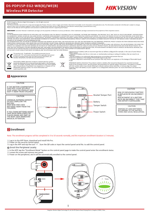
Disclaimer1Appearance2EnrollmentNote:The enrollment progress will be completed in 3to 10seconds normally,and the maximum enrollment duration is 3minutes.1Enroll the Peripheral Locally1.Log in to the APP Store,download and install Hik-Pro.2.Power on the security control panel.3.Log in the APP and tap the icon "+".Scan the QR code or input the control panel serial No.to add the control panel.1.In the APP ,tap the "Enrollment Mode"button on the control panel page to make the control panel enter the enrollment status.2.Loosen the screw and remove rear panel.3.Power on the peripheral,and it will be automatically enrolled to the control panel.CAUTIONRISK OF EXPLOSION IF BATTERY IS REPLACED BY AN INCORRECT TYPE.REPLACEMENT OF A BATTERY WITH AN INCORRECT TYPE THAT CAN DEFEAT A SAFEGUARD.CAUTIONCHEMICAL BURNING DANGER DO NOT SWALLOW THE BATTERYKEEP NEW AND USEDBATTERIES AWAY FROM THE CHILDREN.IF YOU THINK BATTERIES MIGHT HAVE BEEN SWALLOWED OR PLACED INSIDE ANY PART OF THE BODY ,SEEK IMMEDIATE MEDICAL ATTENTION.CAUTIONDISPOSE OF USED BATTERIES ACCORDING TO THE INSTRUC-TIONS AND LOCAL REGULATION.CAUTIONIF THE BATTERY COMPARTMENT DOES NOT CLOSE SECURELY ,STOP USING THE PRODUCT AND KEEP IT AWAY FROM CHILDREN.IndicatorBracket Tamper Port BatteryTamper Switch Power Switch1.Check Signal StrengthEnter the signal checking modethe detector.Solid Green for 3s -Strong Solid Orange for 3s -Medium Solid Red for 3s -Weak Signal Red light flashes for 3S -Failure2.Check the installation environmentNote:Hold the tamper button,and make the device power off and then power on for re-enrollment.3Installation2Enroll the Peripheral with QR and serial No.1.In the APP ,tap the icon "+"and scan the QR code or serial No.on the peripheral.2.Loosen the screw and remove rear panel.3.Power on the peripheral,and it will be automatically enrolled to the control panel.3.Install the DetectorNote:The additional force shall be equal to three times the weight of the equipment but not less than50N.The equipment and its associated mounting means shall remain secure during the installation.After the installation,the equipment, including any associated mounting plate,shall not be damaged.with Screwsa.Knock out the screw holes on the rear panel.with the Sponge TapePaste the device on the wall with sponge tape. b.Secure the rear panel on the wall with four screws.Note:Installing with sponge tape is non ENcompliant.Bracket InstallationCeiling Bracket Fitting (Non EN compliant)Wall Bracket Fitting4TestDetector zones andThe zones and plans of the detector are shown below.Detection Range:FOV 90°,84zones,7levels Mounting Height:1.8to 2.4m (typical 2.1m)Pet Immunity:30Kg4m 8m 12m 15m 010m12m3m 2.4m 2m 1m 0The detector will enter the walk test mode (3minutes)after being enrolled.Trigger the detector within the detection range.If the LED indicator turns blue,the installation position is properly.If the LED indicator is still off,adjust the position of the detector.5Formatting6Set up with AppHold the tamper switch for 8s and power the device on at the same time.The red LED flashes 3times when the formatting operation is completed.Function Zone Type Stay Arm Bypass ChimeEnable Silent Zone Slide to green to enable the chime.Slide to green to make the zone keep silent while alarm is triggered.Select the zone type of the detector.DescriptionYouthe device status including temperature,signal intensity,battery level,lid,arming/disarming,etc.,on the device page.Tap to enter the settings page.Double KnockSlide to green to make the zone alarm with double knock.Cross ZoneSlide to green to bypass the zone from stay arming.If the alarm triggered in both of the linked zones within the set time,two alarm messages will be reported.6Operation Caution and Device Maintenance-All the electronic operation should be strictly compliance with the electrical safety regulations,fire prevention regulations and other related regulations in your local region.-Do not drop the device or subject it to physical shock,and do not expose it to high electromagnetism radiation.Avoid the equipment installation on vibrations surface or places subject to shock (ignorance can cause equipment damage).-Please make sure that the power has been disconnected before you wire,install or dismantle the device.-If smoke,odors or noise rise from the device,turn off the power at once and unplug the power cable,and then please contact the service center.-Do not drop the device or subject it to physical shock,and do not expose it to high electromagnetism radiation.Avoid the equipment installation on vibrations surface or places subject to shock (ignorance can cause equipment damage).-Do not place the device in extremely hot (refer to the specification of the device for the detailed operation temperature),cold,dusty or damp locations,and do not expose it to high electromagnetic radiation.-The device for indoor use shall be kept from rain and moisture.Exposing the equipment to direct sun light,low ventilation or heat source such as heater or radiator is forbidden (ignorance can cause fire danger).-Do not aim the device at the sun or extra bright places.A blooming or smear may occur otherwise (which is not a malfunction however),and affecting the endurance of sensor at the same time.-Improper use or replacement of the battery may result in hazard of explosion.Replace with the same orequivalent type only.Dispose of used batteries according to the instructions provided by the battery manufactur-er.-Do not expose the device to the corrosive gas.Otherwise the equipment damage may occur.-Do not expose the device to the explosive situation.Function DescriptionSensitivitySet the sensitivity of the detector.Higher sensitivity makes the intruder easier to be detected.Swinger limit activationSet the limit times of swinger activition.Trigger Interval,secSet the interval of trigger,and the alarm message will not be repeated within the time.LED Turn On/Off the LED.Polling Rate Set the interval of heartbeat.Signal Strength Test Enter the test mode,and view the LED indication.Detection Zone Test Enter the test mode,and start walk test.Zone BypassBy pass the zone.7SpecificationNote:when the low voltage message appears there will be at least30days of use.。
Control Builder Plus V2_2使用说明
技术资料AC500文档编号:AD220030可升级的控制器灵活的自动化控制系统Control Builder Plus V2.2的使用(1) 在实际的系统构建时,请先确认系统组成设备、装置,如使用过程中对额定值、性能留有余量,以及万一发生故障时将危险降到最低的安全电路等。
(2) 为了安全使用系统,请获取组成系统的各个设备、装置的指南及安装说明书,在确认好包括“安全注意事项”、“安全要点”等内容后再使用。
(3) 本文件所属的产品/系统只允许由具备相关工作经验要求的合格人员进行操作,确认适合系统的规格、法规及规定。
(4) 未经ABB公司许可,严禁擅自对本资料的一部分或全部内容进行篡改及散发。
(5) 本资料的记录内容为测试指导,在应用过程,请根据现场实际情况适当调整,或者咨询ABB技术支持人员。
(6) 我们已对文档中所述内容与硬件和软件的一致性作过检查。
然而不排除存在偏差的可能性,因此我们不保证文档中所述内容与硬件和软件完全一致。
文档中的数据都按规定经过检测,必要的修正值包含在下一版本中。
(7) 本资料的记录内容若有改版,恕不另行通知。
1.序言 (4)1.1.参考文档 (4)1.2.硬件和软件需求 (4)1.3.连接电源 (4)1.4.PLC与电脑连接 (4)2.安装PS501 Control Builder V2.2 (5)3.Control Builder Plus软件的使用 (6)3.1.Control Builder Plus概述 (6)3.2.创建一个新工程 (7)3.3.PLC硬件组态 (8)3.3.1 CPU属性参数配置 (9)3.3.2本地I/O配置 (9)3.3.3 CPU底板集成端口配置 (12)3.3.4 FBP从站接口配置 (14)3.3.5 CS31主站工作模式 (15)3.3.6 通讯模块配置 (16)3.4.安装设备描述文件 (21)4.编程平台CoDeSys概述 (22)4.1.程序组织单元POU (22)4.2.变量 (23)4.3.标准数据类型 (24)4.4.任务管理 (24)4.5.库文件 (26)4.6.编制程序 (28)4.7.离线仿真 (31)5.计算机与PLC联机 (33)5.1.通过串口COM1/COM2与PLC联机 (33)5.2.用以太网与PLC联机 (35)5.3.在Control Builder Plus中与PLC联机 (39)6.强制新值与写入新值 (41)1. 序言本文档面向的读者是那些负责调试和使用AC500的用户。
机器视觉之智能软件CKVisionBuilder --定位-对位
机器视觉之智能软件CKVisionBuilder --定位/对位
CKVisionBuilder --定位/对位
重点工具
使用图像的边缘轮廓特征作为模板,在图像中搜索形状相似的目标。
允许目标存在旋转、缩放、低对比度.模糊、遮挡和噪点、反光和背景复杂等情况把噪点图片换成低对比度。
使用灰度归一化互相关匹配方法,允许目标图像存在亮度和对比度变化和模糊等情况,可用于定位、计数和判断有无等。
定位
CKVisionBuilder的灰度匹配、形状匹配或者轮廓匹配工具可以在即使搜索对象产生缺陷、位置变化、角度变化、对比度降低成大小变化等情况下,也可以稳定搜索,对被测物体的位置偏移进行补正。
也可以发挥卓越的搜索能力
对位
将两个或者两个以上部件彼此之间的相对位置准确调整至一个允许精度范围内,使机械手的中心与产品中心保持一致。
1
图像获取,选取MARK点
2
设置学习参数,输入X,Y,R校准移动量
3。
机器人(机械手)视觉软件
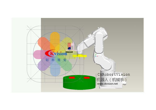
CkRobortVision 机器人(机械手)目录1软件特点2工程开发流程3功能容易使用的机器视觉系统开发平台流程/应用具有强有力的图像处理能力还有丰富图像功能软件特点容易使用的机器视觉系统开发平台:● 不需要编写代码、● 几分钟内可完成视觉项目开发、● 短时间内可通过培训学会操作、● 带有条件分支、循环、判断、子流程指令可完成复杂的程序● 功能强大、算法先进● 支持二次开发,可嵌入到用户程序内软件集合几百种的图像处理工具,图像采集、预处理、图像定位、坐标变换、1D测量、2D测量、Blob分析、条码读取、OCR、图像标定、数据输出、I/O输出、PLC输出等工具,用户需要做的工作就是把不同的工具进行新的组合,具有不同的应用优点:软件特点工程开发流程1:设置图像数据来源支持多种相机的数据输入支持连续采集模式、外触发 输入模式、软件触发输入模式2:设置图像定位及坐标变换图像定位功能是在图像的X、Y、角度发生变化的时候依然能准确地找到图像目标3:设置图像分析工具分析工具包含了尺寸测量、Blob分析、图像对比、条码读取、OCR读取、面积检测、边缘检测、定点测量、圆形测量、亮度检测、直线测量、角度测量、缺陷检测等等4:设置检测结果的输出判断的结果可输出到TCP/IP、PLC、I/O、Excel等软件界面/CkVisionBuilder采用拖动式编程,工具箱内的工具用鼠标拖拉到主流程窗口内添加检测工具检测窗口检测结果九点校正/以太网/接受命令发送数据功能:CkvisionBuilder 具有强有力的图像处理能力还有丰富图像功能图像预处理 BLOB 分析 相机校正 灰度分析 彩色分析条码读取 字符识别(OCR) 1D测量 2 D测量 轮廓匹配灰度匹配 直方图分析 缺陷检测 划痕检测 轮廓检测图像对比 目标计数 面积检测 缺陷线检测 圆形检测性能表: CkVisionBuilder 单个功能的独立测试测试环境:CPU i3-3220@3.3GHZ Image Size 768X576)序号功能平均时间序号功能平均时间0平滑0.669ms10边缘检测0.195 ms 1彩色转灰度0.215 ms11间距检测0.196 ms 2锐化0.352 ms12直线测量0.096 ms 3边缘 1.255 ms13圆形测量0.056 ms 4腐蚀0.189 ms14顶点测量0.308 ms 5膨胀0.189 ms15卡尺测量0.319 ms 6面积检测0.440 ms16灰度匹配0.2543 ms 7亮度检测0.439 ms17轮廓匹配7.127 ms 8图像对比0.201 ms18条码读取0.418 ms 9Blob 2.674 ms19BGA0.775 ms工作原理谢谢观看。
Ck演示程序使用说明

深圳市创科自动化控制技术有限公司目录1、封面。
12、CKVision简介。
3-43、演示范例程序使用说明。
53-1、BLOB分析。
5-7 3-2、像素统计。
7-9 3-3、灰度信息。
9-11 3-4、边缘点测量。
11-12 3-5、边缘线测量。
12-14 3-6、间距测量。
14-16 3-7、卡尺测量。
17-18 3-8、圆形测量。
19-20 3-9、几何模板匹配。
21-23 3-10、灰度模板匹配。
23-26 3-11、圆形检测。
26-28 3-12、条码检测。
28-30 3-13、字符检测。
30-34 3-14、IC定位。
34-36 3-15、基本图像处理。
36-37 4、CKVision相关声明演示版本官方下载地址。
384-1、声明。
38 4-2、演示版本官方下载地址。
382、创科机器视觉软件CKVision简介:Ckvision machine visual software development kit(SDK) is a high-performance machine self-developed by CK company , which is characterized by high precision, fast recognition speed, universal function, insensibility to interference of ambient light, and high reliability.The concept of Ckvision is to provide a simple application development of function package with rich interface ( up to 400 ), and DLL & OCL is supplied as well.VB,VC,and many other development tools are available to it. In the function table of OCX,there is a interface between each two functions to improve the integration of capabilities.What’s more, plenty of sample codes are provided to help developers to identify the development speed of image.So you can just simply call the corresponding function to get what you want. Besides,you can also produce appropriate examples according to customers’demandsCkvision integrates various functions,including BLOB analysing,object counting, geometry matching, intensity matching, color matching, character recognition, bar code recognition, round measuring, round finding, callipers measuring, outer and inner diameter measuring ,color recognition, basic operation of image (binarization, scaling transformation, opening and closing operation, expansion, corrosion, filtering, edge detection ), geometry operation,image combination,image rotation,outline extraction and so on . In addition, special functions could be made according to customers’demands.Ckvision software is based on open system architecture, which is compatible with most popular image collection card , digital camera, imitation camera, linear camera.Besides,development package offers function of getting image data directly from the hardware, which is much more easy to apply.The orientation tool of Ckvision adopted the geometrical characteristics, and the most advanced technology of outline testing to identify the object and model,which have a significant effect on aspects of disordered images,brightness fluctuation, blurred images and overlap objects . The powerful de-fuzzy function could distinguish and identify the object correctly by employing multi-models, even though objects are very similar to each other,the orientation tool can return to the target location, orientation, inverse proportion and user-defined points of reference, including the information of quality ,target and indicators matched.Ckvision has been widely used in electronics, semiconductor, laser, PCB, packaging, measurement, monitoring, game and many other fields.CkVision机器视觉软件开发包是创科公司自行开发的一款高性能的机器视觉软件开发包,特点是精度高,识别速度快,功能全面,对环境光线等干扰不敏感,检测可靠性极高。
- 1、下载文档前请自行甄别文档内容的完整性,平台不提供额外的编辑、内容补充、找答案等附加服务。
- 2、"仅部分预览"的文档,不可在线预览部分如存在完整性等问题,可反馈申请退款(可完整预览的文档不适用该条件!)。
- 3、如文档侵犯您的权益,请联系客服反馈,我们会尽快为您处理(人工客服工作时间:9:00-18:30)。
CKVisionBulider Ver3.0软件使用手册深圳市创科自动化控制技术有限公司版权所有2016-10-11首先感谢您选择使用CKVisionBuilder软件,此软件是深圳市创科自动化控制技术有限公司所开发的一款通用型智能机器视觉软件,是为了简化机器视觉系统的复杂度,降低工程人员的技术要求,不用编写任何代码,只需通过简单的将各个功能模块进行组合就可以完成一个复杂的机器视觉检测项目。
CKVisionBuilder软件包含有定位、测量、检测和识别等算法功能,还拥有强大的逻辑处理能力,可以同时处理多了检测任务,软件兼顾了简易性和灵活性,可以适应大多数项目的需求。
本手册详细介绍了CKVisionBuilder软件V3.0版本的使用和功能,以及各类工具的说明,使用前请仔细阅读此说明书。
第一章软件界面说明 (7)1.程序主界面 (7)1.1菜单栏 (7)1.2主工具栏 (8)1.3显示区域 (8)1.4流程栏 (9)1.5工具箱 (11)1.6数据栏 (11)1.7日志栏 (12)1.8快捷栏 (13)2.程序对话框 (13)2.1系统设置 (13)2.2密码设置 (14)2.3项目设置 (15)2.4流程设置 (16)2.5工具名称设置 (17)2.6用户界面编辑 (17)2.7图像控件设置 (19)2.8消息按钮控件设置 (19)2.9工具按钮控件设置 (20)2.10数值文本控件设置 (20)2.11状态文本控件设置 (21)2.12分组控件设置 (22)2.13数据分析 (23)2.14数据链接 (23)2.15算术表达式 (24)2.17显示图形页面 (26)第二章工具说明 (28)1.相机工具 (28)1.1DSCamera (28)2.图像处理 (29)2.1采集图像 (29)2.2存储图像 (30)2.3图像运算 (30)2.4彩色转灰 (31)2.5预先处理 (32)2.6颜色抽取 (33)3.标定校准 (33)3.1位置补正 (33)3.2坐标系 (34)3.3测量标定 (35)3.4对应点标定 (36)3.5图像矫正 (36)4.检测识别 (36)4.1像素统计 (36)4.2亮度检测 (37)4.3图像对比 (37)4.4BLOB分析 (40)4.5灰度匹配 (43)4.6形状匹配 (45)4.7检测边缘 (48)4.8检测间距 (50)4.9直线测量 (52)4.11字符集合 (56)4.12字符读取 (57)4.13读取条码 (58)4.14读取二维码 (59)4.15颜色监测 (60)4.16颜色识别 (61)5.几何测量 (62)5.1点到点 (62)5.2点到线 (63)5.3线到线 (64)5.4线到圆 (65)6.文件通讯 (67)6.1串行口 (67)6.2以太网 (67)6.3接收文本 (68)6.4发送文本 (69)6.5接收数据 (69)6.6发送数据 (70)6.7Modbus读 (71)6.8Modbus写 (72)6.9播放声音 (74)7.逻辑控制 (74)7.1等待延迟 (74)7.2条件分支 (75)7.3选择分支 (75)7.4循环工具 (76)7.5停止循环 (77)7.6执行流程 (77)7.8数据入队 (78)7.9数据出队 (79)7.10清空队列 (79)8.系统工具 (80)8.1更新画面 (80)8.2计算时间 (80)8.3用户变量 (80)8.4计算变量 (81)8.5设置变量 (82)8.6数据记录 (83)8.7清除记录 (84)8.8数值显示 (85)8.9数据判断 (86)8.10系统时间 (87)8.11生成文本 (88)8.12分解文本 (88)8.13比较文本 (89)9.三维测量 (90)9.13D扫描 (90)9.23D存储 (91)9.33D视图 (92)9.43D高度 (93)9.53D平面 (93)第一章软件界面说明1.程序主界面CKVisionBuilder 软件主界面如下图。
1.1菜单栏菜单栏中有“文件”、“设置”、“操作”、“视图”和“帮助”共五个菜单项,各项菜单中分别有不同的功能设置和操作,详细如下:文件->新建:新建一个工程项目,如当前项目正在编辑,会先提示是否要保存。
文件->打开:从文件中打开一个工程项目,如当前项目正在编辑,会先提示是否会保存。
文件->保存:保存当前的项目,第一次保存会弹出保存对话框,后续则直接覆盖原文件。
文件->另存为:将当前项目另存到其它地方。
设置->系统设置:进入系统设置对话框,详细参见系统设置。
设置->密码设置:进入密码设置对话框,详细参见密码设置。
设置->项目设置:进入项目设置对话框,详细参见项目设置。
设置->界面编辑:进入界面编辑对话框,详细参见界面编辑。
操作->执行流程:单次执行工作流程。
1、菜单3、显示区4、流程栏6、日志栏和数据栏7、状态栏2、主工具栏5、工具箱操作->运行流程:循环执行工作流程。
操作->停止流程:停止循环执行。
1.2主工具栏主工具栏中包含有一些常用的快捷按键,参见以下说明:新建一个项目工程。
从文件中加载一个项目工程。
保存当前项目工程到文件中。
切换当前用户类型。
放大显示当前选择的图像画面。
缩小显示当前选择的图像画面。
还原到1倍显示当前选择的图像画面。
根据显示图像自动适应当前选择的图像画面比例。
单次执行工作流程。
循环执行工作流程。
停止循环执行。
显示软件相关信息。
1.3显示区域显示区域用于显示用户自定义的界面(详细参见用户界面编辑),包括图像、文本和按钮等用户控件。
新建项目时会自动生成一个图像画面,在图像画面中拖到鼠标左键可以移动图像,点击鼠标右键可弹出右键菜单,可以选择存储图像功能,参见下图。
保存原始图像:保存不包含图形的原始的图像数据,灰度图像为8位,彩色图像为24位。
保存带图形图像:保存带有图形和文字的图像,图像位数跟桌面设置一致。
1.4流程栏流程编辑栏用于编辑项目的检测流程图,仅在管理员用户下可用示,可分成三部分,包括编辑工具栏、流程选项卡和编辑区域。
1.4.1编辑工具栏添加一个新流程。
1、编辑工具栏2、流程选项卡3、编辑区域删除当前流程。
设置当前流程,点击后弹出流程设置对话框。
弹出当前选择工具的属性框。
修改当前选择工具的名称和注释信息。
复制当前选择工具。
粘贴被复制的工具到流程中。
删除当前选择的工具。
查找上一个同类型的工具。
查找下一个同类型的工具。
按名称查找工具。
1.4.2流程选项卡点击不同的选项卡可切换到不同的流程,拖拽可以调换选项卡位置顺序。
1.4.3编辑区域编辑区域用于编辑流程,点击可以选择工具,双击可以弹出工具的属性框,右击可以弹出选单(参见下图),可以使用鼠标拖拽工具上下移动来调整位置,工具右边显示“”图标表示OK状态,“”图标表示NG状态,“”图标表示被屏蔽状态,被屏蔽的工具将不会被执行。
属性:弹出工具的属性对话框(不同的工具属性不同)。
名称:弹出修改工具名称和注释对话框。
应用到:弹出应用到对话框,可以将当前工具的参数复制到其它相同类型的工具。
显示:用于将图像数据显示到当前选择的图像画面控件。
激活:勾选为激活状态,不勾选为屏蔽状态。
复制:复制当前工具(会同时复制可折叠部分的工具)粘贴:将已复制的工具粘贴到当前工具的下一个位置。
删除:删除当前选择的工具(会同时删除可折叠部分的工具)。
1.5工具箱工具箱中列出了当前可以使用的检测工具,不同的软件版本有所不同,可以使用软件目录下的Configure.exe程序进行配置,常用的共有8大类,详细如下:相机工具:有当前支持的相机工具。
图像处理:用于图像采集、存储和预处理等功能。
标定校准:位置修正和单位转换工具。
检测识别:实现各种检测功能的工具,有定位、测量和检查等。
几何测量:用于对结果数据进行几何计算的工具。
文件通讯:用于设置通讯端口及接收或发送数据和信号。
逻辑控制:用于控制流程的逻辑功能。
其他功能:用于显示和其它功能。
1.6数据栏数据栏用于显示检测结果数据,通过在流程中使用“数据记录”工具将数据插入到列表中,第一列默认为编号,数据每增加一行则自动加一,从第二列开始为自定义的数据列,在列表中点击右键可以弹出列表功能选单,包括清除记录和保存记录功能(参见下图)。
清除数据:清除当前列表中的所有数据。
保存数据:将当前列表中的所有数据保存到文件中。
装载数据:从文件中导入数据到列表中,文件中的数据格式必须和列表一致。
分析数据:弹出数据分析对话框,对列表中的数据进行分析。
点击数据列的标题会弹出如下选单,可以插入新的字段、删除字段和设置字段,点击“设置字段”选项会弹出设置字段对话框(参见下图)。
插入字段:在列表中当前位置插入新的一列(字段)。
删除字段:删除当前点击的字段。
设置字段:弹出“字段设置”对话框,如下图。
名称:设置字段的名称。
宽度:设置该字段的列宽度。
参与数据分析:是否允许该数据参与数据分析功能。
1.7日志栏日志栏用于记录软件的当前运行信息以及流程中的自定义信息(可使用“生成文本”工具写日志),在列表中点击鼠标右键可弹出如下图的选单。
清除记录:清除日志栏中的所有信息记录。
保存记录:将日志记录保存到文件中。
1.8快捷栏快捷栏仅在技术员用户下可用,可以在管理员用户下设置哪些工具会显示在快捷栏中,双击快捷栏列表中工具名称,可以弹出工具的属性对话框,此功能允许部分开放一些工具给技术员用户进行设置而不用担心会误修改其它工具的参数和流程的逻辑顺序。
2.程序对话框2.1系统设置点击菜单栏中的“设置->系统设置”选项可以进入系统参数设置对话框,系统参数设置用于设置软件的语言及一些基本功能,所有的项目使用相同的系统参数。
双击可以弹出工具的属性对话框更改项目文件目录:变更打开和保存项目时的默认文件夹。
启动时加载默认项目:当软件启动后会自动加载默认的项目文件。
成功加载默认项目后自动运行:仅在“启动时加载默认项目”选项同时勾选时有用。
停止运行时显示提示:点击“停止运行”按钮会先提示“是否要停止运行?”。
将程序窗口显示在顶层:顶层显示程序窗口,以免被其它程序窗口遮挡。
2.2密码设置点击菜单栏中的“设置->密码设置”选项可以进入密码设置设置对话框,在管理员和技术员用户下可以使用,两个用户使用独立的密码,当从操作员用户切换到管理员或技术员用户时需要输入密码才能进入,密码设置对话框参见下图。
旧密码:输入当前使用的就密码,旧密码默认为空。
新密码:输入需要设置的新密码。
确认新密码:再次输入需要设置的新密码。
2.3项目设置项目设置用于设置每个检测项目的基本参数,当新建项目是会重置项目设置在的参数,项目设置参数独立于每个检测项目,存储于项目文件之中。