数字音箱处理器说明
VINAL 数字音频处理器 说明书
通 道A-B均衡 通 道1-9均衡 均 衡+/增益 9段输 入均 衡滤 波 7段输 出均 衡滤 波 参量 低 通频 率-2nd 高 通频 率-2nd 参量 带宽
IN-A: 1 Gain:0.0dB
PEQ: 1000 Hz Q: 1.2
均 衡滤波器: 二阶滤 波器是每 倍频程12dB的 斜率,所有 的滤波器 具有+12/-24B的提升/衰减 范围。 高/低通斜率滤 波器 的范围 从19.8Hz ~21.5KHz。 斜率滤 波器可以 通过 增加或 者衰减音频信号的 高端或者 低端, 最为有效地用作大 范围音色 控制。
24 Bit Digital Crossover
R
28 Bit System Processor
4.2 预设
VT204M具 有20个 可编 程 的预设 模式 ,每个 预设模 式都可以完 全定义 二个输 入和 四个输 出以 及 其各 自的 配置 。 请注 意: 在20个预设定 模式之 外, 还 有一个“快 速拍摄 ”功能 来保 存着工 作设定 ,它可 以 保存 当前 每一步 改动的 设定值 ,这 样在关 闭电源 之前 可以保 存所 有 的改动 。
输 入增 益 通 道A-B 增益 -50~+12
输入增益液晶显示屏显示 IN -A Gain:+0.0dB
输 出 增 益 液 晶 显 示屏 显 示
通 道A-B 通 道1-t1 IN A G ain :+0. 0dB
Pol:Nor
输 出极 性
4.6b 均 衡
VT204M的均衡部 分提供完 整 的参 量均 衡及二 阶斜率滤波器。每 个输入通道具有9 个可选 择的均衡滤波器, 同时每个输出通道 具有7 个可选 择的均 衡滤波器。在所有 情 况下 每个滤 波器可在参量( PEQ )、二 阶低通斜率 ( LSEQ) 和二阶高通斜率 ( HSEQ ) 之间 选择。
K3105-音箱处理器使用说明书、音频处理器说明书

ON 0dB 0dB
OFF
将当前所设置参数存储,最多可以存储 5 组
读取已存储参数
删除已存储参数
进入输入 A/B 通道设置菜单
进入输出 1-6 通道设置菜单
5
K3105‐音箱处理器
使用说明书
表二:Mode 下各模式对应输出的定义
模式 2X2way+sum
2X3way 4way+2sum 4way+2way 4way+way+sum 5way+sum 5way+way
4
K3105‐音箱处理器
使用说明书
表一:主菜单下一二级菜单
一级菜单
项目
功能
Mode
设置输出模式
Shortcut
快捷功能(FREE 状态为未设置 状态,此时可进
行设置)
Save/Load
对当前设置进 行存储、擦除, 或者读取已存
储参数
Channel
对各个通道参 数进行设置
项目 Return
Select mode
初始值
2X2way+2sum
2X3way 4way+2sum 4way+2way 4way+way+sum 5way+sum 5way+way
6way
2X2way+ 2sum
ON/OFF,设置所有通道工作模式 -15db~+15db,设置所有输入通道增益
-45db~0db,设置所有输出通道音量 ON/OFF,设置所有输出通道音频是否输
B (A+B)/2 (A+B)/2
B A
表三:进入 Channel 菜单后三四级菜单的输入通道部分
peavey vsx 26e 和 vsx 48e 数字扬声器处理器使用手册说明书

一旦连接,设备的设置将被加载,图标会变绿,显示在线。使用界面顶部的选项卡导航到所需的界面。 获取屏幕
增益界面上给出了一个系统的概述。除了显示输入和输出增益,静音和极性状态,输入和输出均衡曲线也 可以显示。
2
前面板
10
9
8
7
6
5
43
2
1
10
9
8
7
6
5
43
2
1
(1) USB端口 USB “B” 连接器用于连接主机,通过VSX编辑程序进行编辑控制。 (2) 过程功能按钮 过程功能按钮用于选择一个进程进行编辑。点亮的按键表明它们是可选的。可用的功能是不同的,当一个输入、输出信号或 系统模式(没有选定的输入或输出)进行编辑时,可用的功能是不同的
设备ID #:(Utility 按钮)
该设备的ID号码可以在该界面中设置。ID是用于在编辑程序中识别该设备的,当多个设备连接时。各 设备必须有一个唯一的标识。这是十分重要的,当使用RS 485系列操作界面将多设备连接时。看到部分 串行通信中更多的细节。
以太网地址:(Utility 按钮)
在这里设置以太网、IP地址,以使用以太网端口连接编辑程序。如果编辑地址,一定要注意新地址! 安全锁:(Utility 按钮)
•
交叉/带通滤波器特性如下,巴特沃斯、贝塞尔或Linkwitz-Riley准确比从1阶(6 dB/节)到8阶(48 dB/节)。
•
信号发生器(正弦型,白噪声,粉红噪声)。
•
通道可以与简化立体操作连接。
•
在每个输入端有5个LED段指示灯
•
每个输出端有5个带有限制标志的LED段指示灯
•
VSXe 26 拥有2个XLR平衡输入和6个XLR平衡输出
数字音频处理器使用说明书
重要的安全事项(针对火灾、电击或伤害人体的指示)注意-使用该电器产品时,有以下基本的预防措施:1.使用该产品前请详细阅读全部的安全事项;2.本产品应当接地,如果出现故障时,电流经最小的接地电阻流入大地,以减小电击;本产品的电源线和电源插头都配备安全接地,电源插头应当牢固插入适当的电源座,此电源座应当完全按当地的条例来安装和接地。
警告-接地装置连接不当会导致电击;如果你对产品是否正确接地存在疑问,请委托合格电工或维修人员检查;请不要尝试私自更改产品的电源插头,如果不适合电源插座,可委托合格电工安装适当的电源插座;3.为了减小伤害的风险,当产品在小孩附近使用时,要严密监管;4.请勿在湿度很大的地方使用机器,例如靠近浴缸、洗面盆、厨房水槽、湿度大的地下室或者靠近游泳池和湖泊;5.该产品应当安装与通风良好的地方;6.该产品必须远离热源,例如电暖炉、电热毯或者其他产生热量的产品;7.该产品的电源类型必须符合操作指示或者产品上标明的类型;8.该产品要配备一条两端的电源线(一端的插片长过另一端)。
这是安全装置。
如果你无法把电源插头插入电源插座,请联系电工来更换旧插座。
9.长时间不使用时,请把电源线从电源插座中拔出,从电源插座拔出电源线时,请勿拉扯电源线,应当抓住电源插头将其拔出;10.细心护理,请勿让杂物或者液体从其缝隙掉进机器内;11.当有下列情况时,应委托合格维修人员修理:A.电源线或电源插头已被损坏B.杂物或者液体已掉进机内C.产品已被雨淋D.产品已不能正常操作或在演出中出现明显变化E.产品已跌坏或外观损坏12.当出现在用户维修指南中没有描述的情况时,请勿尝试私自修理,应当委托合格的维修人员修理;13.警告-勿让重物积压或踩踏电源线,切忌拉、拔或强力扭曲电源线。
请勿滥用电源线,不合格的电源线可能导致火灾或对人构成伤害。
目录重要的安全事项(针对火灾、电击或伤害人体的指示) (1)目录 (2)一、设备架构 (3)二、软件操作说明 (4)2.1菜单栏和工具栏 (5)2.1.1文件 (5)2.1.2本地设置 (5)2.1.3设备设置 (6)1)用户管理 (6)2)场景管理 (6)3)网络设置 (7)4)串口设置 (8)5)设备升级 (8)2.2音频输入模块 (8)2.2.1输入源 (9)2.2.2均衡器 (9)2.3自动混音器 (10)2.4反馈消除 (12)2.5噪声抑制器 (12)2.6音频输出模块 (13)2.6.1来源于 (14)2.6.2音箱管理 (14)2.6.3限幅器 (15)2.7中控命令生成器操作说明 (16)2.7.1简易生成中控命令 (16)2.7.2中控命令生成器操作说明 (16)三、常见问题 (18)一、设备架构设备前面板指示灯:(1)PWR:电源指示灯,接通电源后,灯亮表示设备供电正常,灯灭表示设备供电有异常;(2)STATUS:状态指示灯,灯闪表示系统运行正常,在升级过程中灯会长亮;(3)IN:输入信号指示灯,灯不亮表示该通道无信号输入,灯亮绿表示该输入通道有信号输入,灯亮红表示该输入通道静音;OUT:输出信号指示灯,灯不亮表示该通道无信号输出,灯亮绿表示该输出通道有信号输出,灯亮红表示该输出通道静音;设备后面板接口:(1)AC220V:电源插头,支持AC100V~240V供电,50~60Hz;(2)M-LAN:网络接口,连接PC,在线编辑和命令收发控制;(3)RS232:通信接口,连接外部中控设备/支持摄像跟踪;(4)RESET:系统复位按钮;(5)INPUT:模拟音频MIC\LINE输入接口;OUTPUT:模拟音频输出接口;二、软件操作说明软件的安装:软件支持vista、XP、window7、window8操作系统,在安装软件前,请确保电脑已经安装DotNet Framework3.5。
数字音频处理器使用说明书

重要的安全事项(针对火灾、电击或伤害人体的指示)注意-使用该电器产品时,有以下基本的预防措施:1.使用该产品前请详细阅读全部的安全事项;2.本产品应当接地,如果出现故障时,电流经最小的接地电阻流入大地,以减小电击;本产品的电源线和电源插头都配备安全接地,电源插头应当牢固插入适当的电源座,此电源座应当完全按当地的条例来安装和接地。
警告-接地装置连接不当会导致电击;如果你对产品是否正确接地存在疑问,请委托合格电工或维修人员检查;请不要尝试私自更改产品的电源插头,如果不适合电源插座,可委托合格电工安装适当的电源插座;3.为了减小伤害的风险,当产品在小孩附近使用时,要严密监管;4.请勿在湿度很大的地方使用机器,例如靠近浴缸、洗面盆、厨房水槽、湿度大的地下室或者靠近游泳池和湖泊;5.该产品应当安装与通风良好的地方;6.该产品必须远离热源,例如电暖炉、电热毯或者其他产生热量的产品;7.该产品的电源类型必须符合操作指示或者产品上标明的类型;8.该产品要配备一条两端的电源线(一端的插片长过另一端)。
这是安全装置。
如果你无法把电源插头插入电源插座,请联系电工来更换旧插座。
9.长时间不使用时,请把电源线从电源插座中拔出,从电源插座拔出电源线时,请勿拉扯电源线,应当抓住电源插头将其拔出;10.细心护理,请勿让杂物或者液体从其缝隙掉进机器内;11.当有下列情况时,应委托合格维修人员修理:A.电源线或电源插头已被损坏B.杂物或者液体已掉进机内C.产品已被雨淋D.产品已不能正常操作或在演出中出现明显变化E.产品已跌坏或外观损坏12.当出现在用户维修指南中没有描述的情况时,请勿尝试私自修理,应当委托合格的维修人员修理;13.警告-勿让重物积压或踩踏电源线,切忌拉、拔或强力扭曲电源线。
请勿滥用电源线,不合格的电源线可能导致火灾或对人构成伤害。
目录重要的安全事项(针对火灾、电击或伤害人体的指示) (1)目录 (2)一、设备架构 (3)二、软件操作说明 (4)2.1菜单栏和工具栏 (5)2.1.1文件 (5)2.1.2本地设置 (5)2.1.3设备设置 (6)1)用户管理 (6)2)场景管理 (6)3)网络设置 (7)4)串口设置 (8)5)设备升级 (8)2.2音频输入模块 (8)2.2.1输入源 (9)2.2.2均衡器 (9)2.3自动混音器 (10)2.4反馈消除 (12)2.5噪声抑制器 (12)2.6音频输出模块 (13)2.6.1来源于 (14)2.6.2音箱管理 (14)2.6.3限幅器 (15)2.7中控命令生成器操作说明 (16)2.7.1简易生成中控命令 (16)2.7.2中控命令生成器操作说明 (16)三、常见问题 (18)一、设备架构设备前面板指示灯:(1)PWR:电源指示灯,接通电源后,灯亮表示设备供电正常,灯灭表示设备供电有异常;(2)STATUS:状态指示灯,灯闪表示系统运行正常,在升级过程中灯会长亮;(3)IN:输入信号指示灯,灯不亮表示该通道无信号输入,灯亮绿表示该输入通道有信号输入,灯亮红表示该输入通道静音;OUT:输出信号指示灯,灯不亮表示该通道无信号输出,灯亮绿表示该输出通道有信号输出,灯亮红表示该输出通道静音;设备后面板接口:(1)AC220V:电源插头,支持AC100V~240V供电,50~60Hz;(2)M-LAN:网络接口,连接PC,在线编辑和命令收发控制;(3)RS232:通信接口,连接外部中控设备/支持摄像跟踪;(4)RESET:系统复位按钮;(5)INPUT:模拟音频MIC\LINE输入接口;OUTPUT:模拟音频输出接口;二、软件操作说明软件的安装:软件支持vista、XP、window7、window8操作系统,在安装软件前,请确保电脑已经安装DotNet Framework3.5。
数字音频处理器的调试
数字音频处理器的调试现在数字音频处理器越来越多地运用到工程当中了,对于有基础有经验的人来说,处理器是一个很好用的工具,但是,对于一些经验比较欠缺的朋友来说,看着一台处理器,又是一大堆英文,不免有点无从下手。
其实不用慌,我来介绍一下处理器使用步骤。
以一个2进4出的处理器控制全频音箱+超低音音箱的系统为例:1、首先是用处理器连接系统,先确定好哪个输出通道用来控制全频音箱,哪个输出通道用来控制超低音音箱,比如你用输出1、2 通道控制超低音,用输出3、4 通道控制全频。
接好线了,就首先进入处理器的编辑(EDIT)界面来进行设置,进入编辑界面不同的产品的方法不同,具体怎么进入,去看说明书。
2、利用处理器的路由(ROUN)功能来确定输出通道的信号来自哪个输入通道,比如你用立体声方式扩声形式,你可以选择输出通道1、3的信号来自输入A,输出通道的2、4的信号来自输入B。
信号分配功能不同的产品所处的位置不同,有些是在分频模块里,有些是在增益控制模块里,这个根据说明书的指示去找。
3、根据音箱的技术特性或实际要求来对音箱的工作频段进行设置,也就是设置分频点。
处理器上的分频模块一般用CROSSOVERX-OVEF 表示,进入后有下限频率选择(HPF和上限频率选择(LPF),还要滤波器模式和斜率的选择。
首先先确定工作频段,比如超低音的频段是40-120赫兹,你就把超低音通道的HPF 设置为40, LPF设置为120。
全频音箱如果你要控制下限,就根据它的低音单元口径,设置它的HPF大约在50- 100Hz,。
处理器滤波器形式选择一般有三种,bessel,butterworth 和linky-raily ,我以前有帖子专门说明过三种滤波器的不同之处,这里不赘述。
常用的是butterworth 和linky-raily 两种,然后是分频斜率的选择,一般你选24dB/oct 就可以满足大部分的用途了。
4、这个时候你需要检查一下每个通道的初始电平是不是都在0dB位置,如果有不是0的,先把它们都调到0位置上,这个电平控制一般在GAIN功能里,DBX的处理器电平是在分频器里面的,用G表示。
教你怎样使用数字音频处理器

现在数字音频处理器越来越多地运用到工程当中了,对于有基础有经验的人来说,处理器是一个很好用的工具,但是,对于一些经验比较欠缺的朋友来说,看着一台处理器,又是一大堆英文,不免有点无从下手。
其实不用慌,我来介绍一下处理器使用步骤,以一个2进4出的处理器控制全频音箱+超低音音箱的系统为例1、首先是用处理器连接系统,先确定好哪个输出通道用来控制全频音箱,哪个输出通道用来控制超低音音箱,比如你用输出1、2通道控制超低音,用输出3、4通道控制全频。
接好线了,就首先进入处理器的编辑(EDIT)界面来进行设置,进入编辑界面不同的产品的方法不同,具体怎么进入,去看说明书。
2、利用处理器的路由(ROUNT)功能来确定输出通道的信号来自哪个输入通道,比如你用立体声方式扩声形式,你可以选择输出通道1、3的信号来自输入A,输出通道的2、4的信号来自输入B。
信号分配功能不同的产品所处的位置不同,有些是在分频模块里,有些是在增益控制模块里,这个根据说明书的指示去找。
3、根据音箱的技术特性或实际要求来对音箱的工作频段进行设置,也就是设置分频点。
处理器上的分频模块一般用CROSSOVER或X-OVER表示,进入后有下限频率选择(HPF)和上限频率选择(LPF),还要滤波器模式和斜率的选择。
首先先确定工作频段,比如超低音的频段是40-120赫兹,你就把超低音通道的HPF设置为40,LPF设置为120。
全频音箱如果你要控制下限,就根据它的低音单元口径,设置它的HPF大约在50-100Hz,。
处理器滤波器形式选择一般有三种,bessel,butterworth和linky-raily,我以前有帖子专门说明过三种滤波器的不同之处,这里不赘述。
常用的是butterworth和linky-raily两种,然后是分频斜率的选择,一般你选24dB/oct就可以满足大部分的用途了。
4、这个时候你需要检查一下每个通道的初始电平是不是都在0dB位置,如果有不是0的,先把它们都调到0位置上,这个电平控制一般在GAIN功能里,DBX的处理器电平是在分频器里面的,用G表示。
DSP1000 MKII
上述屏幕显示是暂时的,之后屏幕显示“默认屏幕”. DSP1000 MKII出厂有 9 个预设. 初始化之后, DSP1000 MKII LCD 将显示第一个预设,或者上次关机前运行的预设. 如果 DSP1000 MKII 是 第一次 激活 “默认屏幕” 将显示 第一个 已经 嵌入的预设
DSP1000 MKII数字音箱处理器
技术参数如有更改,恕不另行通知
DSP1000 MKII 数字音箱处理器
快速使用手册 参照如下前板, 用控制键和功能键操作DSP1000 MKII.
● 启动 打开 DSP1000 MKII, LCD会显示该机器型号
DSP1000 MKII Speaker Management
Interface Setup
ESC ENTER
ESC ENTER
ESC ENTER
ESC ENTER
ESC ENTER
ESC ENTER
ESC ENTER
ESC ENTER
ESC ENTER
ESC ENTER
ESC ENTER
4 UTILITY MENU:...... << Security Utilities >>
SYSTEM UTILITY: Ramps on changes >>
1.7 <<
SYSTEM UTILITY: Software Version >>
2 UTILITY MENU:......
<< Program Utilities
>>
ENTER
ESC
2.1
专业音响 - C-MARK 教你怎样使用数字音频处理器
4、这个时候你需要检查一下每个通道的初始电平是不是都在0dB位置,如果有不是0的,先把它们都调到0位置上,这个电平控制一般在GAIN功能里,DBX的处理器电平是在分频器里面的,用G表示。
5、现在就可以接通信号让系统先发出声音了,然后用极性相位仪检查一下音箱的极性是否统一,有不统一的,先检查一下线路有没有接反。如果线路没接反,而全频音箱和超低音的极性相反了,可以利用处理器输出通道的极性翻转功能(polarity或pol)把信号的极性反转,一般用Nomal或“+”表示正极性,用INV或“-”表示负极性。
以一个2进4出的处理器控制全频音箱+超低音音箱的系统为例:
1、首先是用处理器连接系统,先确定好哪个输出通道用来控制全频音箱,哪个输出通道用来控制超低音音箱,比如你用输出1、2通道控制超低音,用输出3、4通道控制全频。接好线了,就首先进入处理器的编辑(EDIT)界面来进行设置,进入编辑界面不同的产品的方法不同,具体怎么进入,去看说明书。
7、接下来就该进行均衡的调节了,可以配合测试工具也可以用耳朵来调,处理器的均衡用EQ来表示,一般都是参量均衡(PEQ),参量均衡有3个调节量,频率(F),带宽(Q或OCT),增益(GAIN或G)。具体怎么调,就根据产品特性、房间特性和主观听觉来调了,这个就自己去想了。
8、均衡调好后,就要进行限幅器的设置了,处理器的限幅器用LIMIT来表示,进去以后一般有限幅电平(THRESHOLD),压缩比(RATIO)的选项,你要做限幅就要先把压缩比RATIO设置为无穷大(INF),然后配合功放来设置限幅电平,变成限幅器后,启动时间ATTACK和恢复时间RELEASE就不用去理了。DBX处理器的限幅器用PEAKSTOP来表示,启动后,直接设置限幅电平就可以了,至于怎么调限幅器,我有专门的帖子,自己去看,
LAX-DSP4000数字音频处理器说明

DSP4000——数字音频处理器DSP4000是一台高级先进的4输入8输出数字音频信号处理器。
它可配置立体声4路2分频,立体声3分频,立体4分频,乃至8分频架构。
它采用最合适的高性能零件,以求取得最好的音频效果,最低的失真及噪音。
DSP4000采用32比特(可扩展至40比特)的数码处理器作为中心处理,并采用浮点设计,这一设计可大大提升动态范围,比24比特的设计质量高出很多倍。
这一设计亦是今天音频处理器之中最高级的设计。
DSP4000有友好的、容易使用的用户界面。
它给输入/输出信号控制上提供最大值控制和灵活性。
用户只需按下Channel键便可直接控制音量及其它参数。
DSP4000可以通过附带的软件连接计算机的RS232接口作为远程操控。
DSP4000数字音频处理器特点◆ 4信号通道输入,8信号通道输出◆采用高性能的96k24Bit模拟数字转换器◆超级的音频信号处理质量◆中央处理器及数码处理日后均可以不断升级◆每一个输入及输出通道设有6个参量均衡器,均为+15dB 增益及-30dB衰减,Q值由 0.01至 2.50◆每一个输入及输出通道均设有静音键开关 (带灯显示)◆延时器可以选择时间或距离作为单位,方便计算◆可通过附送的计算机软件连接计算机作远程操控及修改参量◆可储存30个节目◆每一个通道输出的压限均可以控制启动及释放时间◆网络远程控制功能DSP4000内部流程处理图DSP4000技术参数:输入\输出4路输入,8路输出输入阻抗>10KΩ输出阻抗50 Ω最大输入、输出电平+20dBu类型电子平衡式音频性能频率响应+/- 0.1dB (20 - 20KHz)动态范围115dB typ (unweighted)共模抑制比> 60dB (50 - 10KHz)。
惠威Dx46 FIR-DRIVE数字音响处理器说明书
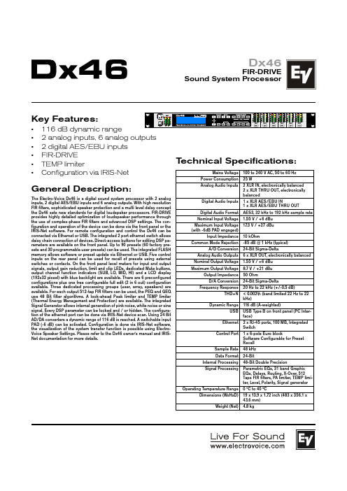
Dx46FIR-DRIVESound System ProcessorKey Features:• 116 dB dynamic range• 2 analog inputs, 6 analog outputs • 2 digital AES/EBU inputs • FIR-DRIVE • TEMP limiter• Configuration via IRIS-NetGeneral Description:The Electro-Voice Dx46 is a digital sound system processor with 2 analog inputs, 2 digital AES/EBU inputs and 6 analog outputs. With high resolution FIR filters, sophisticated speaker protection and a multi level delay concept the Dx46 sets new standards for digital loudspaker processors. FIR-DRIVE provides highly detailed optimization of loudspeaker performance through the use of complex-phase FIR filters and advanced DSP settings. The con-figuration and operation of the device can be done via the front panel or the IRIS-Net software. For remote configuration and control the Dx46 can be connected via Ethernet or USB. The integrated 2 port ethernet switch allows daisy chain connection of devices. Direct-access buttons for editing DSP pa-rameters are available on the front panel. Up to 90 presets (60 factory pre-sets and 30 programmable user presets) can be used. The integrated FLASH memory allows software or preset update via Ethernet or USB. Five control inputs on the rear panel can be used for recall of presets using external switches or contacts. On the front panel level meters for input and output signals, output gain reduction, limit and clip LEDs, dedicated Mute buttons,output channel function indicators (SUB, LO, MID, HI) and a LCD display (192x32 pixesl) with blue backlight are available. There are 6 preconfigured configurations plus one free configurable full edit (2 in 6 out) configuration available. Three dedicated processing groups (user, array, speakers) are available. For each output 512-tap FIR filters can be used, the PEQ and GEQ use 48 Bit filter algorithms. A look-ahead Peak limiter and TEMP limiter (Thermal Energy Management and Protection) are available. The integrated Signal Generator allows internal generation of pink noise, white noise or sine signal. Every DSP parameter can be locked and / or hidden. The configura-tion of the ethernet port can be done via IRIS-Net device scan. Using 24 Bit AD/DA converters a dynamic range of 116 dB is reached. A switchable input PAD (-6 dB) can be activated. Configuration is done via IRIS-Net software,the visualization of the system transfer function is possible using Electro-Voice Speaker Settings. Please refer to the Dx46 owner‘s manual and IRIS-Net documentation for more details.T echnical Specifications:Mains Voltage 100 to 240 V AC, 50 to 60 Hz Power Consumption 25 WAnalog Audio Inputs2 XLR IN, electronically balanced 2 x XLR THRU OUT, electronically balancedDigital Audio Inputs 1 x XLR AES/EBU IN1 x XLR AES/EBU THRU OUT Digital Audio Format AES3, 32 kHz to 192 kHz sample rate Nominal Input Voltage 1.55 V / +6 dBu Maximum Input Voltage (with -6dB PAD engaged)17.3 V / +27 dBu Input Impedance10 kOhmCommon Mode Rejection-85 dB @ 1 kHz (typical)A/D Conversion 24-Bit Sigma-DeltaAnalog Audio Outputs 6 x XLR OUT, electronically balanced Nominal Output Voltage 1.55 V / +6 dBu Maximum Output Voltage8.7 V / +21 dBu Output Impedance 50 OhmD/A Conversion 24-Bit Sigma-DeltaFrequency Response20 Hz to 22 kHz (+/-0.5 dB)THD+N< 0.002% (band limited 22 Hz to 22 kHz)Dynamic Range116 dB (A-weighted)USB USB Type B on front panel (PC Inter-face)Ethernet 2 x RJ-45 ports, 100 MB, Integrated SwitchControl Port1 x 6-pole Euro blockSoftware Configurable for Preset Recall Sample Rate 48 kHz Data Format24-BitInternal Processing 48-Bit Double PrecisionSignal ProcessingParametric EQs, 31 band Graphic EQs, Delays, Routing, X-Over, 512 Taps FIR filters, PA limiter, TEMP limi-ter, Level, Polarity, Signal generator Operating Temperature Range0 °C to 40 °CDimensions (WxHxD)19 x 13.9 x 1.72 inch (483 x 356.1 x 43.6 mm)Weight (Net)4.8 kgDx46FIR-DRIVESound System Processor Block Diagram:Dx46FIR-DRIVESound System Processor DSP Signal Flow Chart:12000 Portland Avenue South, Burnsville, MN 55337Phone: 952/884-4051, Fax: 952/884-0043© Bosch Communications Systems 03/2010Part Number F01U126854 Vs 01U.S.A. and Canada only. For customer orders, contact Customer Service at :800/392-3497 Fax: 800/955-6831Europe, Africa, and Middle East only. For customer orders, contact Customer Service at:+ 49 9421-706 0 Fax: + 49 9421-706 265Other International locations. For customer orders, Contact Customer Service at:+ 1 952 884-4051 Fax: + 1 952 887-9212For warranty repair or service information, contact the Service Repair department at:800/685-2606For technical assistance, contact Technical Support at: 866/78AUDIOSpecifications subject to change without notice.Dimensions Drawings:Rear View:Dx46 Part Number:Agency ApprovalsDx46, 120 V -- F01U126855CE Dx46, 230 V -- F01U126854FCC, ICCB。
peavey vsx 26e和vsx 48e数字扬声器处理器使用说明书

FCC/ICES Compliancy StatementThis device complies with Part 15 of the FCC rules and Industry Canada license-exempt RSS Standard(s). Operation is subject to the following two conditions: (1) this device may not cause harmful interference, and (2) this device must accept any interference received, that may cause undesired operation.Le présent appareil est conforme aux CNR d’lndustrie Canada applicables aux appareils radio exempts de licence. L’exploitation est autorisée aux deux conditions suivantes: (1) I’appareil ne doit pas produire de brouillage, et (2) I’utilisateur de I’appareil doit accepter tout brouillage radioélectrique subi, même si le brouillage est susceptible d’en compromettre le fonctionnement.Warning: Changes or modifications to the equipment not approved by Peavey Electronics Corp. can void the user’s authority to use the equipment.Note – This equipment has been tested and found to comply with the limits for a Class B digital device, pursuant to Part 15 of the FCC Rules. These limits are designed to provide reasonable protection against harmful interference in a residential installation. This equipment generates, uses, and can radiate radio frequency energy and, if not installed and used in accordance with the instructions, may cause harmful interference to radio communications. However, there is no guarantee that interference will not occur in a particular installation. If this equipment does cause harmful interference to radio or television reception, which can be determined by turning the equipment off and on, the user is encouraged to try and correct the interference by one or more of the following measures.•Reorient or relocate the receiving antenna.•Increase the separation between the equipment and receiver.•Connect the equipment into an outlet on a circuit different from that to which the receiver is connected.•Consult the dealer or an experienced radio/TV technician for help.CautionThe equipment complies with FCC radiation exposure limits set forth for an uncontrolled environment.VSX™ 26e and VSX™ 48eDigital Loudspeaker ProcessorsThe VSXe processors are DSP-based, loudspeaker management systems that boast a 96kHz sample rate and a floating point DSP processor for quiet accurate filter response. The crossover filters are fully adjustable and any input can be routed to any output. The VSX® Editor Program for PC allows complete remote setup and operation via the front panel USB port or by the rear panel Ethernet network connection. Files can also be saved and loaded using this interface software.This manual covers both the VSX 26e and VSX 48e DSP processors. The units are essentially identical except for the number of inputs and outputs. Please read this guide carefully to ensure your personal safety as well as the safety of your equipment.Features• Balanced Inputs: VSX 26e 2, VSX 48e 4• Balanced Outputs: VSX 26e 6, VSX 48e 8• 96 kHz Sample rate• 24 bit Delta-Sigma A/D and D/A converters• Dynamic range input to output greater than 109 dB (A-weighted) or 107 dB (unweighted)• Every input features Gain, Mute, HP and LP filters, 8 bands of PEQ, polarity and Delay (680 mS),• Every output features: 9 bands of PEQ, gain, compressor/limiter, polarity, Delay (680 mS), mute, and crossover/band-pass filters• EQ filter types include: PEQ, Low-Shelf, Hi-Shelf, Low-Pass, High-Pass, All-Pass1 and All-Pass2.• Crossover/Band-pass filters feature Butterworth, Bessel or Linkwitz-Riley alignments from 1st order (6 dB/Oct) to 8th order (48 dB/Oct).• Signal generator (sine, white noise, pink noise).• Channels can be linked for simplified stereo operation.• 5 segment LED meters on each input• 5 segment LED meters with limit indication on each output• 2 XLR balanced inputs and 6 XLR balanced outputs VSXe 26• 4 XLR balanced inputs and 8 XLR balanced outputs VSXe 48• Maximum input and output level +20 dBu, XLR balanced inputs and outputs.• Frequency response 20 Hz to 20 kHz +0, -1 dB• THD+N < 0.01% at 1 kHz.• Security lock• USB B port for setup and control• Ethernet port for setup and control.• Dimensions (HxWxD) 1.75" x 19" x 8" / 45mm x 480mm x 20.5mm• Weight 5.2 lbs /2.88 kg• PC Editor Programs allow complete remote setup and operation via USB or Ethernet.NOTE: The VSX processors can be setup and operated both from the front panel and from the VSX Editor running on a PC. The PC can be connected to the VSX via USB or Ethernet.(1)USB portThe USB "B" connector is used to connect a host computer for editing and control using the VSX Editor Program.(2) Process Function ButtonsThe process-function buttons are used to select a process for editing. Lighted buttons illuminate to indicate they are available selections. The available functions are different when an input, output or system mode (no input or output selected) for editing. GAIN: Used to access channel gain controls Delay: Used to access channel Delay controlsCOMP: Available only for output editing, used to access channel compressor/limiter controls. PEQ: Used to access channel equalization controlsXo v er:Used to access the low-pass filter and high-pass filter controls. POLARITY: Used to access channel polarity normal or invert controls MATRIX: Available only for output editing, used to route inputs to outputs. EXIT: Exit channel editing.(3) Parameter KnobThe parameter knob is used by pressing and rotating to edit processing parameters.(4) System Function Buttons Utility:Utility functions include setting Unit ID#, IP address, Security Lock and password, input signal or signal generator, copy channel and Delay units.Recall: Used to load saved system presets. Save : Used to save system presets.(5) LCD DisplayUsed in conjunction with the front panel controls to edit processing parameters.(6) Output Mute ButtonsPressing the mute button alternately mutes and un-mutes the corresponding output. The button lights red when muted.(7) Output Edit ButtonsPress this button to begin editing processes for the selected output. The specific process to edit can be selected using the process-function buttons on the right.(8) Input/Output Monitoring:Input: The 5 segment LED meters indicate the input signal level with the top Clip LED illuminating before the onset ofclipping. Although you will want to avoid clipping, you will achieve best performance if the 0 LED lights frequently during loud passages.Output: The top LED illuminates to indicate the signal has reached the threshold set in the compressor/limiter and that gain reduction is occurring. The bottom 4 LEDs form the output level meters indicating signal level. The Clip LED illuminates before the onset of clipping. Although you will want to avoid clipping, you will achieve best performance if the 0 LED flashes frequently d uring loud passages.(9) Input Edit ButtonsPress this button to begin editing processes for the selected input. The specific process to edit can be selected using the process-function buttons on the right.(10) Input Mute ButtonsPressing the mute button alternately mutes and un-mutes the corresponding input. The button lights red when muted.intuitive interface.Opening screen shows product name and firmware version.Pressing the utility button opens the screens for system wide settings. Each press of the utility button advances to the next screen in the sequence. You can press the "Exit" button at any time to return to the main screen.The ID number of the unit can be set in this screen. The ID is used with the Editor program to identify this unit when multiple units are connected. Each unit must have a unique identifier. It is most important whenunits are connected together using the RS 485 serial interface. See the section on serial communication for Set the Ethernet, IP address here for connection to the Editor program using the Ethernet port. Make sure to note the new address if you edit address!Once on this screen, the parameter knob is used to set the password. Press to advance and rotate to changeeach digit. A "Y" or "N" will appear allowing to engage the lock "Y" or turn it off "N".During normal operation, the analog inputs on the rear of the VSX are routed to the outputs. However, the VSX has an internal signal generator that can be used for setup and testing. Rotating the parameter knob allows you to select Analog Input, Pink Noise, White Noise or a Sine-Wave as the input source for all inputs. The new selection will blink on the screen. Press the Parameter knob to select. Y ou may wish to mute outputs that you do not wish to receive the signal from the generator. Analog input must be selected for those inputs to function.Settings can easily be copied from one input channel to another input or from one output to another. Rotatethe parameter encoder to select the parameter.The units used to set delays can be selected on this screen. The options are milli-Seconds (mS), meters (m) orfeet (ft)Rotate the Parameter knob to select the desired preset number then press to load.Select the desired user storage location using the parameter knob then Press. Enter a name for the preset and then press the parameter knob again when the "Y" appears to complete the save.The next section of controls are used to make adjustments to a particular input or output.Begin by pressing the "EDIT" button (7 and 9) for the channel you wish to adjust. The edit function buttons at the right side of the front panel that apply to the channel selection will light. The function selected will blink.Input Edit functions: Gain, PEQ, Link, Delay, X-Over and Polarity.Output Edit functions: Gain, PEQ, Link, Delay, X-Over, Matrix, Comp and Polarity.While editing, you can select another function or another channel by pressing the appropriate button.Press Exit to return to the main screen.The input and output gain can be adjusted in a range of -60 dB to +12 dB in 0.1 dB increments. For best oper-ation, the gain should not be set at extreme settings (0dB is optimal). It is always best to adjust the signal level driving the VSX input so that the Y ellow LED lights on louder signals. When using the crossover on an output, you may need to increase the gain to achieve sufficient signal level to drive the amplifier. If you find that youneed to turn down an output very far below 0 dB, you will get quieter operation if you reduce the amplifier inputlevel control instead.The input channels have 8 bands of equalization available and the outputs have 9. The EQ band is indicated in the upper left corner of the display. (Band 1 is shown above) The parameter selected for adjustment will blink on the screen. Press the parameter knob to select a parameter for editing. Rotate the knob to adjust.F= Frequency, Q is inverse of Bandwidth. High Q equates to narrow bandwidth. G= Gain.The EQ types available are: Peak/Dip (PEAK), Low-Shelf (L-SHLF), High-Shelf (H_SHLF), Low-Pass (L-PASS), High-Pass (H-PASS), All-Pass 1 (A-PAS1), All-Pass 2 (A-PAS2)"On" is active and "By"= Bypass.Many times, in particular for stereo signals, you may want to make the same adjust to two or more channels at the same time. Using the link function, inputs can be linked to other inputs and outputs can be linked to other outputs. The check marks on the above screen indicate linkage. When channels are linked, the edit buttons forthose channels will blink simultaneously when editing.Up to 680 milli-Seconds of delay can be added to any input or output. The delay resolution is 1 sample or 10.4 micro-Seconds.Although the button is labeled X-OVER and that is how these functions are often used, each input and output have very flexible high-pass and low-pass filters that can be configured for many applications.To activate the filter use the parameter control to select bypass on the screen and change it to the desired filter type. There are 3 different filter alignments available, Butterworth, Bessel and Linkwitz-Riley. The filter slopes of 6 dB/Octave to 48 dB/Octave can be selected.The Matrix screen is only available when editing an output. This is where the inputs that drive each output are connected. The above screen shows input "A" as the signal source for output 1. If multiple inputs are selected,their signals are summed.The compressor screen is only available when editing an output. The compressor parameters are: T= Threshold, R= Ratio, AT= Attack Time and RT= Release Time. The threshold is roughly equal to the limiting level in dBu. The limit LED corresponding to the output channel will light when the threshold is exceeded. The status is also displayed in the computer editor.0= Normal polarity. 180= Reverse polarity.The VSX processors can be setup and controlled using the VSX Editor which runs on a Windows computer. To control the VSX, the computer can be connected to the VSX via USB, Ethernet, RS-232 or RS-485. For most applications, USB or Ethernet will be the preferred solutions.Connect the computer to the VSX using a USB cable connected to USB jack on the front of the unit.When connected to the editor, front panel controls are locked out.Connecting a computer to the VSX via Ethernet.The VSX processors use a "Static" IP address. Setting the address of the unit and ID# is described in the utility section of the manual. The Editor must be set the matching IP address and ID# in order to connect.An Ethernet cable can be connected directly to most computers if only one unit is being controlled. In most cases you will want to use an Ethernet router or WiFi router.If the computer is connected before launching the VSX editor software, the software will search for connected devices. If it does not connect, check to be sure the IP address and device ID# of the unit match the settings in the editor. Also, make sure the VSX IP address is set in the network range of your computer and router. Y ou can then click scan or click the offline Icon in the upper right corner of the screen to scan and connect.Once connected, the setting from the unit will be loaded and the icon will turn green and indicate online. Usethe Tabs at the top of the screen to navigate to the desired screen.The gain screen above gives a good overview of the system. In addition to showing input and output gains, mute and polarity status, Input and output equalization curves can be displayed.The Compressor screen displays the settings of all 8 output compressors along with signal level, and limit status. The transfer function of a selected output is also displayed.All of the input and output delays are shown in the above screen. Delays can be adjusted using the sliders at the bottom, by sliding the speakers at the top or by direct typed entry. To directly enter the delay time, double click the delay time and type a new value. If you hold down the left mouse button on a slider, you can fine adjust the delay by using the up and down arrow buttons on the keyboard.The delay display units can be selected on the right.The input sources for each output are routed on the Matrix screen. Click the input button below the output to select. If more than one source is selected those inputs will sum. A graphical representation of the routing is given at the top. Inputs and outputs can also be labeled in this screen.The input equalization can be adjusted using this screen. When you select a PEQ band # at the bottom left of the screen, the parameters for that band can be adjusted using the PEQ Parameter sliders. A PEQ band can also be adjusted by selecting the corresponding band on the graph with the mouse and dragging it to set frequency and amplitude. While holding mouse button down, the Q can be adjusted using the + and - keys. If you double click on a parameter in the PEQ matrix, you can directly type in a new value. The graph can display either the mag-nitude of filter responses or the resulting phase response. The graph of other inputs can also be overlaid on the screen by clicking boxes on top of the graph.The output equalization can be adjusted using this screen. When you select a PEQ band # at the bottom left of the screen, the parameters for that band can be adjusted using the PEQ Parameter sliders. A PEQ band can also be adjusted by selecting the corresponding band on the graph with the mouse and dragging it to set frequency and amplitude. While holding mouse button down, the Q can be adjusted using the + and - keys. If you double click on a parameter in the PEQ matrix, you can directly type in a new value. The graph can display either the magnitude of filter responses or the resulting phase response. The graph of other outputs can also be overlaid on the screen by clicking boxes on top of the graph.Store (1)The store button at the bottom of the screen duplicates the store button on the front panel of the VSX. The user can select one of 30 user storage locations to save the current settings.Recall (2)The Recall button at the bottom of the screen duplicates the Recall button on the front panel of the VSX. The user can Recall one of 30 user stored presets.File > Open Open a saved *.prs "preset" file. If you wish to open a preset (*.prs) file and load it into the VSX, you must be connected and "Online" when you open the file. If the VSX is "offline" it will load only into the editor program. If you then connect the editor to the VSX going 'Online", the VSX settings will be loaded into the editor over-writing the editor settings.File >Save Save the current settings in the editor into a *.prs "preset" file.File >Upload This uploads all of the presets from the VSX and saves them to a *.unt "unit file.File >Download This loads a *.unt file containing all of the unit presets into the connected unit. The VSX will be "offline" when complete.Input Impedance:20 k Ohms Output Impedance:100 Ohms Frequency response Input to Output: +0/ -0.5 dB 10 Hz to 21 kHz+0/ -1.0 dB 10 Hz to 32 kHz Maximum Input level:+20 dBu Maximum Output level:+20 dBu THD + N @ 1 kHz:0.007%Noise floor 22-22kHz-87 dBu unweighted -89 dB A-Weighted Dynamic range >107 dB unweighted 109 dB A-Weighted.Crosstalk between channels:Less than -100 dB at 1 kHz.LED Meter Input:LED Color LabeldBu * dBFS *Red Clip +15 -5Y ellow +5 +5 -15Green 0 0 -20Green -10 -10 -30Green -30 -30 -50LED Meter Output:LED Color LabeldBu * dBFS *AmberLimit - -Red Clip +15-5Green 0 0 -20Green -10 -10 -30Green -30 -30 -50*Note References:0 dBFS = Maximum signal level before clipping (Full Scale)0 dBu = 0.775 V rmsLatency analog input to analog output:3.5 mSSample Rate: 96 kHzEthernet Interface: 10.0 MbpsaddressStaticIPv4RS 232 and RS 485: Baud Rate: 115200D atabits: 8NoneParity:bits: 1StopRS 232/485 Pinout: RS 232 RX: Pin 2RS 232 TX: Pin 3RS 232 GND: Pin 5RS 485 +: Pin 7RS 485 -: Pin 8 Dimensions: 1.75 x 19 x 8.25 inches H x W x D44.5 x 482 x 210 mmNet Weight: 5.28 pounds 2.39 kgAC power Input Voltage 195 to 240 V AC 50-60 HzPower Consumption 15 WattsFuse F2AL 250V (5x20mm)RS 232, RS 485 message formats are available in the VSX editor help files.21。
数字音频处理器功能及作用介绍

数字音频处理器功能一般的数字处理器,内部的架构普遍是由输入部分和输出部分组成,其中属于音频处理部分的功能一般如下:输入部分一般会包括,输入增益控制(INPUT GAIN),输入均衡(若干段参数均衡)调节( INPUT EQ)输, 入端延时调节( INPUT DELAY,)输入极性(也就是大家说的相位)转换( input polarity)等功能。
而输出部分一般有信号输入分配路由选择(ROUNT,)高通滤波器(HPF),低通滤波器( LPF),均衡器(OUTPUT EQ),极性( polarity ),增益( GAIN),延时( DELAY),限幅器启动电平( LIMIT)这样几个常见的功能。
主要特点输入增益:这个想必大家都明白,就是控制处理器的输入电平。
一般可以调节的范围在 12 分贝左右。
输入均衡:一般数字处理器大多数使用 4-8 个全参量均衡,内部可调参数有3 个,分别是频率、带宽或 Q 值、增益。
第一和第三两个参数调节大家一般都明白,比较困惑的是带宽(或 Q 值),这个我也不想多说,只告诉大家一个基本的概念:带宽,用 OCT表示, OCT=,调节范围,调节效果和 31 段均衡一样, OCT=,调节范围与效果和 15段均衡差不多, OCT=1,调节范围效果和 7 -9 段均衡差不多。
OCT值越大,说明你调节范围越宽。
而 Q值,它可以理解为 OCT的倒数,Q=oct,OCT=对应的 Q 值大约就是 Q=4,大家可以自己换算一下。
在进行调节的时候,如果你不是很明白,就把这个带宽值设为左右(或Q=,然后选择需要调的频率,这样,你就可以按照 31 段均衡的调法和感觉来调增益了。
输入延时:这个功能就是让这台处理器的输入信号一进了就进行一些延时,一般在这台处理器和它所控制的音箱作为辅助时候做整体的延时调节。
输入极性转换:可以让整台处理器的极性相位在正负之间转换,省掉你改线了。
以上是输入部分的介绍:信号输入分配路由选择( ROUNT):作用是让这个输出通道选择接受哪一个输入通道过来的信号,一般可以选择 A(1)路输入, B(2)路输入或混合输入( A+B或 mix mono),如果你选择 A,那么这个通道的信号就来自输入 A,不接受输入 B的信号,如果选择 A+B,那么,不管 A 或者 B路哪个有信号,这个通道都会有信号进来。
音箱处理器中文说明

1
特点简介
DIGITAL SPEAKER PR OCESSOR 2 IN 4 OUT AUDIO MANAGEMENT SYSTEM
DIGITAL SPEAKER PR OCESSOR 2 IN 6 OUT AUDIO MANAGEMENT SYSTEM
4
后背板控制简介
1
CAUTION
TO REDUCE THE RISK OF FIRE REPL ACE ONLY WITH THE SAME TYPE
2 00 - 240 VA C :T 31 5m A /2 5 0V AC
BA LANCED INPUTS
2 =S I GN AL
1=G N D
2
1
CLIP 0 -6 -12 -18
-24
CLI P 0 -6 -12 -18
-24
OUTPUTS
POWER POWER
注意 为避免受到电击
请勿开启
小心:为避免受到电击,请勿移开(底) 盖,如遇到问题亦不要尝试私自修理,请委 托合格的维修人员修理。
在等边三角形内的电击符号警惕用户在产 品内部存在非绝缘的危险电压,有可能对 人体造成相当危险的电击。
BACK
NEXT
FREQ
Q
MENU
ENTER
BY PA S S
QUIT
BACK
NEXT
FREQ
Q
MENU
ENTER
BY PA S S
QUIT
GAIN
G A IN MUTE
A
B
CLIP 0 -6 -12 -18
怎样使用数字音频处理器

怎样使用数字音频处理器(转载)喇叭杀手教你怎样使用数字音频处理器处理器使用步骤。
以一个2进4出的处理器控制全频音箱+超低音音箱的系统为例:1、首先是用处理器连接系统,先确定好哪个输出通道用来控制全频音箱,哪个输出通道用来控制超低音音箱,比如你用输出1、2通道控制超低音,用输出3、4通道控制全频。
接好线了,就首先进入处理器的编2、利用处理器的路由(ROUNT)功能来确定输出通道的信号来自哪个输入通道,比如你用立体声方式扩声形式,你可以选择输出通道1、3的信号来自输入A,输出通道的2、4的信号来自输入B。
信号分配功能不同的产品所处的位置不同,有些是在分频模块里,有些是在增益控制模块里,这个根据说明书的指示去找。
根据音箱的技术特性或实际要求来对音箱的工作频段进行设置,也就是设置分频点。
处理器上的分频模块一般用CROSSOVER 或X-OVER表示,进入后有下限频率选择(HPF)和上限频率选择(LPF),还要滤波器模式和斜率的选择。
首先先确定工作频段,比如超低音的频段是40-120赫兹,你就把超低音通道的HPF设置为40,LPF设置为120。
全频音箱如果你要控制下限,就根据它的低音单元口径,设置它的HPF大约在50-100Hz,。
处理器滤波器形式选择一般有三种,bessel,butterworth和linky-raily,我以前有帖子专门说明过三种滤波器的不同之处,这里不赘述。
常用的是butterworth和linky-raily两种,然后是分频斜率的选择,一般你选24dB/oct就可以满足大部分的用途了。
4、这个时候你需要检查一下每个通道的初始电平是不是都在0dB位置,如果有不是0的,先把它们都调到0位置上,这个电平控制一般在GAIN功能里,DBX的处理器电平是在分频器里面的,用G表示。
现在就可以接通信号让系统先发出声音了,然后用极性相位仪检查一下音箱的极性是否统一,有不统一的,先检查一下线路有没有接反。
ALTO DCX2345 数字音频处理器 说明书
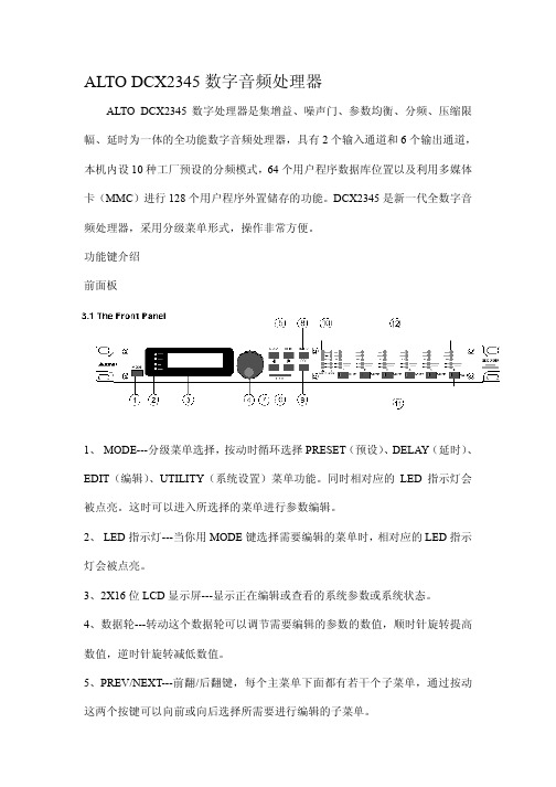
ALTO DCX2345数字音频处理器ALTO DCX2345数字处理器是集增益、噪声门、参数均衡、分频、压缩限幅、延时为一体的全功能数字音频处理器,具有2个输入通道和6个输出通道,本机内设10种工厂预设的分频模式,64个用户程序数据库位置以及利用多媒体卡(MMC)进行128个用户程序外置储存的功能。
DCX2345是新一代全数字音频处理器,采用分级菜单形式,操作非常方便。
功能键介绍前面板1、 MODE---分级菜单选择,按动时循环选择PRESET(预设)、DELAY(延时)、EDIT(编辑)、UTILITY(系统设置)菜单功能。
同时相对应的LED指示灯会被点亮。
这时可以进入所选择的菜单进行参数编辑。
2、 LED指示灯---当你用MODE键选择需要编辑的菜单时,相对应的LED指示灯会被点亮。
3、2X16位LCD显示屏---显示正在编辑或查看的系统参数或系统状态。
4、数据轮---转动这个数据轮可以调节需要编辑的参数的数值,顺时针旋转提高数值,逆时针旋转减低数值。
5、P REV/NEXT---前翻/后翻键,每个主菜单下面都有若干个子菜单,通过按动这两个按键可以向前或向后选择所需要进行编辑的子菜单。
6、N A VIGATION CURSOR KEYS---光标移动键,每个子菜单中都有若干个可以编辑的参数选择,按动这两个键,可以选择需要编辑的参数,选中的参数会闪烁。
7、C ARD---储存卡插入口,在这个插口插入MMC储存卡,利用PRESET(预设)菜单下,可以对该储存卡进行写入、读出等操作。
8、E NTER---确认键,按此键可以对所选择的菜单或编辑的参数数值进行确认。
9、E SC---取消键,按此键可以对所选择的菜单或编辑的参数数值进行取消操作,返回上一级菜单。
10、输入电平指示表,实时指示A/B两个输入通道输入电平的强弱数值。
11、 MUTE---静音按键,按下后将关闭相应输出通道的输出信号,相对应的红色LED指示灯将点亮。
数字音频处理器 用户手册
用户手册重要安全说明请详细阅读本使用说明书:为了您的安全和能更快地熟练使用这台机器,使用前请先详细阅读并理解本书中所有的安全与使用说明。
请遵守所有的警告与注意事项:为了您能更加安全地使用这台机器,请遵守在设备上和说明书中所有的警告与注意事项。
请严格按照制造厂商的方法来安装本机器,请安装它在易通风散热的地方。
请勿阻塞机器上所有的通风散热孔。
不要用诸如报纸、桌布、窗帘等之类的物品覆盖着本机器;不要将本机器放置在绒毛很长的地毯或棉被上。
禁止在靠近水或潮湿的地方使用本机器,如浴缸、厕所、潮湿的地下室、游泳池旁等;禁止将水或其它液体之类的东西滴入或倒入机内;不要在靠近热源的地方使用本机器,如加热器、暖气机、电热炉、大功率放大器等各种易发热设备。
请勿将易发生危险的物器放置在机器上。
例如装有液体的物品、花瓶之类的物品;请将易燃易爆如酒精、天那水之类的化学用品远离本机器。
请勿用化学溶剂如酒精之类的物品清洁本机器,否则会对机器表面造成损伤,必要时清洁的干布擦试。
应避免电源线及插头受到损伤或损坏。
不要强行拉扯电源线及其它组件,若要移动本装置请拔下电源插头。
当打雷或闪电、或较长时间不使用本机器,请立即关闭本机的电源并拔出交流电源插头。
若发生以下异常情况时,请立即关闭本机器的电源并拔下电源插头并联系专业人士维修。
为防止发生火灾或触电危险,切勿自行拆开机盖进行维修。
(1当电源线或电源插头受到操有破损,如线芯露出或断线。
(2)机器冒烟、有异味或出现其它异常情况时。
(3)金属之类或其它异物掉入机器内;水或其它液体进入机器内;或被雨淋后。
(4机器跌落在地上后或工作不正常等情况时。
电源开关中长方形“1”表示接通电源;圆型“0”表示断开电源。
请注意:所有设备必须接地。
为了您的安全,务必不能拆除设备的接地电缆或用其它的方式使用接地无效。
本机器与电网相连时,必须总是带有安全引线。
请您务必注意,设备的安装和操作都只能由专业人员进行。
在安装期间和安装后的操作过程中,操作人员必须有良好的接地,否则静电放电等会影响设备的正常工作特性。
- 1、下载文档前请自行甄别文档内容的完整性,平台不提供额外的编辑、内容补充、找答案等附加服务。
- 2、"仅部分预览"的文档,不可在线预览部分如存在完整性等问题,可反馈申请退款(可完整预览的文档不适用该条件!)。
- 3、如文档侵犯您的权益,请联系客服反馈,我们会尽快为您处理(人工客服工作时间:9:00-18:30)。
产品名称:DP-240(标准版)※精选双精度的DSP处理器和32bit的内部数据通道,具有特别宽阔的动态范围和优良的音质。
※采样率高,损耗低,动态范围可达>105dB。
※方便灵活多分频模式,DP240 2路输入4路输出的,可设置成4种模式,包括2X2路分频、3+1路分频、4 路分频和2路超低音分频,并带有限幅器。
※每个参数段的增益调整范围为+15dB至-30dB,中心频率范围为20HZ-20KHZ,Qs范围为0.4到128,每个通道输入均带有3段参量均衡,输出均带有5段参量均衡,均衡器(PEQ)带宽范围为1/36到4倍频程(Oct),参数可进行大范围调整,用于优化系统的频率响应,每次开机各通道输出音量渐出,更稳定的保护了音乐信号对音箱的瞬间冲击。
※每通道有独立的静音和编辑按键。
具有批量修改与编辑参数功能。
每输出通道都有一个独立的限幅器,其启动时间、释放时间和门槛值等参数均可在大范围内调整;每个输入与输出端有6个LED电平显示,电平表显示是相对于门槛值的动态余量,电平表的时间常数会自动跟踪限幅器的时间常数,使指示更加精确。
※可变的高通虑波器和低通虑波器的斜率可设置为:6dB、12dB、18dB、24d B、36dB或48dB每倍频程,并可选择其响应为:巴特沃斯(Butterworth)、林克维茨-瑞莱(Linkwitz-Riley)、贝塞儿(Bessel)及12dB的多种可变值斜率选择;高通及低通虑波器的参数可以独立调整,能够实现不对称的分频功能。
※输入通道矩阵控制。
灵活实用的输入、输出通道复制功能,对系统各通道参数进行调整时更快捷、方便。
※三个电压传感型360°旋转编码器,用于控制虑波器的参数,操作方便且符合一般人的操作习惯。
在调整时,在显示屏(LCD)上会同步显示出虑波器的各项参数值。
※每路输出的延时独立可调整,最大延时为6.979mS,最小调整步距为0.021mS。
※ 所有设置的状态可保存在记忆中,并且有关机自动保存设置功能,20个用户自定义存储模式,USB和RS232串口默认联机接口,可由PC控制本机,在PC控制软件友好直观的电脑操作界面上做所有的预设,软件界面可中英文切换,操作更加方便简单,稳定性强,性价比高,更即人性化,以及多级完善的安全锁功能。
※ 20X2蓝色背光源白色字符LCD显示屏,显示更清楚直观,6X6段输入输出精确数字电平表;外形尺寸:482mm*180mm*44mm。
※电源采用开关电源供电,宽电压输入,使用范围更宽,从AC95-AC250/50-60Hz,速度更快,自动调整,适用范围广,稳定性高,适用全球电压使用。
产品名称:DP-260(标准版)※道精选双精度的DSP处理器和32bit的内部数据通道,具有特别宽阔的动态范围和优良的音质。
※采样率高,损耗低,动态范围可达>105dB。
※方便灵活多分频模式,DP260 2路输入6路输出的,可设置成5种模式,包括2X2+2路分频、2X3路分频、4+2路分频、5+1路分频和6路分频,并带有限幅器。
※每个参数段的增益调整范围为+15dB至-30dB,中心频率范围为20HZ-20KHZ,Qs范围为0.4到128,每个通道输入均带有3段参量均衡,输出均带有5段参量均衡,均衡器(PEQ)带宽范围为1/36到4倍频程(Oct),参数可进行大范围调整,用于优化系统的频率响应。
每次开机各通道输出音量渐出,更稳定的保护了音乐信号对音箱的瞬间冲击。
※每通道有独立的静音和编辑按键。
具有批量修改与编辑参数功能。
每个输出通道都有一个独立的限幅器,其启动时间、释放时间和门槛值等参数均可在大范围内调整;每个输入与输出端有6个LED电平显示,电平表显示是相对于门槛值的动态余量,电平表的时间常数会自动跟踪限幅器的时间常数,使指示更加精确。
※可变的高通虑波器和低通虑波器的斜率可设置为:6dB、12dB、18dB、24d B、36dB或48dB每倍频程,并可选择其响应为:巴特沃斯(Butterworth)、林克维茨-瑞莱(Linkwitz-Riley)、贝塞(Bessel)及12dB的多种可变值斜率选择;高通及低通虑波器的参数可以独立调整,能够实现不对称的分频功能。
※输入通道矩阵控制。
灵活实用的输入、输出通道复制功能,对系统各通道参数进行调整时更快捷、方便。
※三个电压传感型360°旋转编码器,用于控制虑波器的参数,操作方便且符合一般人的操作习惯。
在调整时,在显示屏(LCD)上会同步显示出虑波器的各项参数值。
※每路输出的延时独立可调整,最大延时为6.979mS,最小调整步距为0.021mS。
※所有设置的状态可保存在记忆中,并且有关机自动保存设置功能,20个用户自定义存储模式,USB和RS232串口默认联机接口,可由PC控制本机,在PC控制软件友好直观的电脑操作界面上做所有的预设,软件界面可中英文切换,操作更加方便简单,稳定性强,性价比高,更即人性化,以及多级完善的安全锁功能。
※20X2蓝色背光源白色字符LCD显示屏,显示更清楚直观,8X6段输入输出精确数字电平表;外形尺寸:482mm*180mm*44mm。
※电源采用开关电源供电,宽电压输入,使用范围更宽,从AC95-AC250/50-60Hz,速度更快,自动调整,适用范围广,稳定性高,适用全球电压使用。
产品名称:DP-260A(加强版)DP260A主要特点:※精选双精度的DSP处理器和32bit的内部数据通道,具有特别宽阔的动态范围和优良的音质。
※采样率高,损耗低,动态范围可达>105dB。
※方便灵活多分频模式,DP260A 2路输入6路输出的,可设置成5种模式,包括2X2+2路分频、2X3路分频、4+2路分频、5+1路分频和6路分频,并带有限幅器。
※每个参数段的增益调整范围为+15dB至-30dB,中心频率范围为20HZ-20KHZ,Qs范围为0.4到128,每个通道输入均带有15段图示均衡(GEQ)和9段参量均衡(PEQ),输出均带有8段参量均衡,均衡器(PEQ)带宽范围为1/36到4倍频程(Oct),参数可进行大范围调整,用于优化系统的频率响应。
每次开机各通道输出音量渐出,更稳定的保护了音乐信号对音箱的瞬间冲击。
※每通道有独立的静音和编辑按键。
每个输出通道都有一个独立的限幅器,其启动时间、释放时间和门槛值等参数均可在大范围内调整;每个输入与输出端有6个LED电平显示,电平表显示是相对于门槛值的动态余量,电平表的时间常数会自动跟踪限幅器的时间常数,使指示更加精确。
※可变的高通虑波器和低通虑波器的斜率可设置为:6dB、12dB、18dB、24d B、36dB或48dB每倍频程,并可选择其响应为:巴特沃斯(Butterworth)、林克维茨-瑞莱(Linkwitz-Riley)、贝塞儿(Bessel)及12dB的多种可变值斜率选择;高通及低通虑波器的参数可以独立调整,能够实现不对称的分频功能。
※输入通道矩阵控制。
灵活实用的输入、输出通道复制功能,对系统各通道参数进行调整时更快捷、方便。
※三个电压传感型360°旋转编码器,用于控制虑波器的参数,操作方便且符合一般人的操作习惯。
在调整时,在显示屏(LCD)上会同步显示出虑波器的各项参数值。
※每路输入、输出通道延时独立可调整,最大延时为6.979mS,最小调整步距为0.021mS。
※所有设置的状态可保存在记忆中,并且有关机自动保存设置功能,20个用户自定义存储模式,USB和RS232串口默认联机接口,可由PC控制本机,在PC控制软件友好直观的电脑操作界面上做所有的预设,软件界面可中英文切换,操作更加方便简单,稳定性强,性价比高,更即人性化,以及多级完善的安全锁功能。
※20X2蓝色背光源白色字符LCD显示屏,显示更清楚直观,8X6段输入输出精确数字电平表;外形尺寸:482mm*180mm*44mm。
※电源采用开关电源供电,宽电压输入,使用范围更宽,从AC95-AC250/50-60Hz,速度更快,自动调整,适用范围广,稳定性高,适用全球电压使用。
产品名称:DP-480DP480主要特点:※精选双精度的DSP处理器和32bit的内部数据通道,具有特别宽阔的动态范围和优良的音质。
※采样率高,损耗低,动态范围可达>105dB。
※方便灵活多分频模式,DP480 4路输入8路输出处理,机内已配置10种工作模式,4 x 2-way Crossover; 2 x 3-way, and 2 Aux;2 x 3-way + mono sub; 2 x 4-way Crossover; 1 x 5-way, and 3 Aux;mono distribution; stereo distribution; LCRS with mono subs; 4 x4 Processor; Muted, Flat Startup并带有限幅器,在各种配置模式中,所有参数均可调整。
※每个参数段的增益调整范围为+6dB至-40dB,中心频率范围为20HZ-20KHZ,Qs范围为0.5到128,每个输入通道都包括输入增益控制,每一个通道都包括独立的分频限制器,输出均带有5段参量均衡,均衡器(PEQ)带宽范围为1/36到4倍频程(Oct),参数可进行大范围调整,用于优化系统的频率响应。
每次开机各通道输出音量渐出,更稳定的保护了音乐信号对音箱的瞬间冲击。
※每个输出通道有独立的静音按键。
每个输出通道都有一个独立的限幅器,其启动时间、释放时间和门槛值等参数均可在大范围内调整;每个输入与输出端有7个LED电平显示,电平表显示是相对于门槛值的动态余量,电平表的时间常数会自动跟踪限幅器的时间常数,使指示更加精确。
※可变的高通虑波器和低通虑波器的斜率可设置为:6dB、12dB、18dB、24d B、36dB或48dB每倍频程,并可选择其响应为:巴特沃斯(Butterworth)、林克维茨-瑞莱(Linkwitz-Riley)、贝塞儿(Bessel)及12dB的多种可变值斜率选择;高通及低通虑波器的参数可以独立调整,能够实现不对称的分频功能。
※任意通道之间参数设置可以自由复制,对系统各通道参数进行调整时更快捷、方便。
输出增益及相位控制,参数加锁,避免误操作.每个通道包括输入增益控制,独立的分频限制器※三个电压传感型360°旋转编码器,用于控制虑波器的参数,操作方便且符合一般人的操作习惯。
在调整时,在显示屏(LCD)上会同步显示出虑波器的各项参数值。
※每路输出通道延时独立可调整,最大延时为7mS,最小调整步距为0.021mS。
※所有设置的状态可保存在记忆中,并且有关机自动保存设置功能,30个用户自定义存储模式,USB和RS232串口联机接口,可由PC控制本机,在PC控制软件友好直观的电脑操作界面上做所有的预设,操作更加方便简单,稳定性强,性价比高,更即人性化,以及多级完善的安全锁功能。
