EELS mapping step-by-step
制作日式烤鳗鱼饭英语作文

制作日式烤鳗鱼饭英语作文Title: Writing a Document on Making Japanese Grilled Eel Rice Japanese Grilled Eel Rice, also known as Unagi Don, is a popular and delicious dish in Japanese cuisine. The combination of juicy and flavorful grilled eel over a bed of steamed rice creates a harmonious blend of textures and tastes. In this document, we will explore the process of preparing this traditional Japanese delicacy step by step.Firstly, the key ingredient required for making Japanese Grilled Eel Rice is, of course, the eel itself. Eels aretypically sold skinned and precooked in Japanese markets, making the preparation process much simpler. However, if you prefer to use fresh eel, you will need to skin and debone it before grilling.To begin, prepare the eel by slicing it into thick pieces. Next, the eel pieces are typically marinated in a sauce made from a blend of soy sauce, mirin, sake, and sugar. This marinade imparts a sweet and savory flavor to the eel, enhancing itstaste during grilling.Once the eel has marinated for an adequate amount of time, it is time to grill it. The eel is placed on a grill and cooked until the surface becomes slightly charred and crispy, while the inside remains tender and succulent. The grilling process helpsto caramelize the marinade, creating a rich and umamipacked flavor.While the eel is grilling, the rice should be prepared. Japanese shortgrain rice is the preferred choice for making Unagi Don, as its sticky texture complements the eel perfectly. Cook the rice according to the package instructions and keep it warm until ready to assemble the dish.To assemble the Japanese Grilled Eel Rice bowl, start by placing a generous portion of steamed rice in a bowl. Arrange the grilled eel pieces on top of the rice, drizzling any remaining marinade over the dish. Garnish with thinly sliced green onions and toasted sesame seeds for added flavor andvisual appeal.In Japan, Japanese Grilled Eel Rice is often served with a side of pickles or miso soup to balance out the richness of the eel. The dish is enjoyed yearround but is especially popular during the summer months when eel is believed to provide stamina and energy to combat the heat.In conclusion, making Japanese Grilled Eel Rice is a rewarding culinary experience that allows you to savor the flavors of traditional Japanese cuisine. With the right ingredients and techniques, you can recreate this beloved dishin your own kitchen and enjoy a taste of Japan's rich culinary heritage.。
尚学堂SSH-188P

版权所有:尚学堂科技
尚学堂
手把手教程
Struts+Hibernate+Spring
我们将需要创建如下文件
一个ActionForm – LoginActionForm.java 一个Action – LoginAction.java struts-config.xml文件 三个页面 登录页面 – login.jsp 登录成功提示页面 – login_success.jsp 登录失败提示页面 – login_error.jsp 就这些!没别的了!!
版权所有:尚学堂科技
尚学堂
手把手教程
Struts+Hibernate+Spring
创建LoginActionForm.java
ActionForm是一个JavaBean,需继承 org.apache.struts.action.ActionForm类, 它捕获通过HTTP请求传送的参数 ActionForm针对每个HTML表单中的字段 具有一个对应的属性 ActionServlet匹配请求中的参数和 ActionForm中的属性,并调用ActionForm 中的setter方法,将参数传入ActionForm 我们的login.jsp有username和password 两个表单字段(下面将会看到),所以, 我们需要定义ActionForm中相应的setter 方法:setUsername和setPassword方法 ActionForm中的getter/setter方法,可以 通过Eclipse集成环境,自动生成 ActionForm中的内部属性全部定义为私有 的(private),并通过公共(public)的 getter/setter方法来访问
版权所有:尚学堂科技
Open Cascade手册(6)

Data ExchangeSTEP Import/ExportUser’s GuideVersion 6.3 / September 20082 Overview Copyright © 2008, by Open CASCADE S.A.S.PROPRIETARY RIGHTS NOTICE: All rights reserved. No part of this material may be reproduced ortransmitted in any form or by any means, electronic, mechanical, or otherwise, including photocopyingand recording or in connection with any information storage or retrieval system, without the permissionin writing from Open CASCADE S.A.S.The information in this document is subject to change without notice and should not be construed as acommitment by Open CASCADE S.A.S. Open CASCADE S.A.S. assures no responsibility for anyerrors that may appear in this document.The software described in this document is furnished under a license and may be used or copied onlyin accordance with the terms of such a license.CAS.CADE and Open CASCADE are registered trademarks of Open CASCADE S.A.S. Other brandor product names are trademarks or registered trademarks of their respective holders.NOTICE FOR USERS:This User Guide is a general instruction for Open CASCADE study. It may be incomplete and evencontain occasional mistakes, particularly in examples, samples, etc. Open CASCADE S.A.S. bears noresponsibility for such mistakes. If you find any mistakes or imperfections in this document, or if youhave suggestions for improving this document, please, contact us and contribute your share to thedevelopment of Open CASCADE Technology: bugmaster@Tour Opus 1277, Esplanade du Général de Gaulle92914 PARIS LA DEFENSEFRANCEContents1. OVERVIEW (5)2. READING STEP (6)2.1.P ROCEDURE (6)2.2.D OMAIN COVERED (6)2.2.1. Assemblies (6)2.2.2. Shape representations (6)2.2.3. Topological entities (7)2.2.4. Geometrical entities (7)2.3.D ESCRIPTION OF THE PROCESS (7)2.3.1. Loading the STEP file (7)2.3.2. Checking the STEP file (7)2.3.3. Setting the translation parameters (8)2.3.4. Performing the STEP file translation (14)2.3.5. Getting the translation results (14)2.3.6. Selecting STEP entities for translation (15)2.4.M APPING STEP ENTITIES TO O PEN CASCADE SHAPES (17)2.4.1. Assembly structure representation entities (17)2.4.2. Models (19)2.4.3. Topological entities (19)2.4.4. Geometrical entities (20)2.5.T OLERANCE MANAGEMENT (23)2.5.1. Values used for tolerances during reading STEP (23)2.5.2. Initial setting of tolerances in translating objects (23)2.5.3. Transfer process (24)2.6.C ODE ARCHITECTURE (27)2.6.1. List of the classes (27)2.6.2. API classes (27)2.6.3. Graph of calls (27)2.7.E XAMPLE (28)3. WRITING STEP (30)3.1.P ROCEDURE (30)3.2.D OMAIN COVERED (30)3.2.1. Writing geometry and topology (30)3.2.2. Writing assembly structures (30)3.3.D ESCRIPTION OF THE PROCESS (31)3.3.1. Initializing the process (31)3.3.2. Setting the translation parameters (31)3.3.3. Performing the Open CASCADE shape translation (34)3.3.4. Writing the STEP file (35)3.4.M APPING O PEN CASCADE SHAPES TO STEP ENTITIES (35)3.4.1. Assembly structures and product information (35)3.4.2. Topological shapes (36)3.4.3. Geometrical objects (37)3.5.T OLERANCE MANAGEMENT (39)3.6.C ODE ARCHITECTURE (40)3.6.1. List of the classes (40)3.6.2. API classes (40)3.6.3. Graph of calls (41)3.7.E XAMPLE (42)4. API FOR READING/WRITING STEP (43)4.1.O VERVIEW (43)44.2.P ACKAGE STEPC ONTROL (43)4.2.1. General description (43)4.2.2. Enumeration STEPControl_StepModelType (43)4.2.3. Class STEPControl_Controller (44)4.2.4. Class STEPControl_Reader (45)4.2.5. Class STEPControl_Writer (46)4.2.6. Class STEPControl_ActorRead (48)4.2.7. Class STEPControl_ActorWrite (49)4.3.P ACKAGE STEPC ONSTRUCT (51)4.3.1. General description (51)4.3.2. Class STEPConstruct_Styles (51)4.3.3. Class STEPConstruct_Part (54)5. PHYSICAL STEP FILE READING AND WRITING (59)5.1.A RCHITECTURE OF STEP R EAD AND W RITE CLASSES (59)5.1.1. General principles (59)5.1.2. Complex entities (59)5.2.P HYSICAL FILE READING (59)5.2.1. Loading a STEP file and syntactic analysis of its contents (60)5.2.2. Mapping STEP entities to arrays of strings (60)5.2.3. Creating empty Open CASCADE objects that represent STEP entities (60)5.2.4. Initializing Open CASCADE objects (60)5.2.5. Building a graph (60)5.3.H OW TO ADD A NEW ENTITY IN SCOPE OF THE STEP PROCESSOR (60)5.4.P HYSICAL FILE WRITING (61)5.4.1. Building a references graph (62)5.4.2. Transferring data from the model to a sequence of strings (62)5.4.3. Writing the sequence of strings into the file (62)5.5.H OW TO ADD A NEW ENTITY TO WRITE IN THE STEP FILE (62)6. USING DRAW (63)6.1.DRAW STEP C OMMANDS O VERVIEW (63)6.2.S ETTING THE INTERFACE PARAMETERS (63)6.3.R EADING A STEP FILE (63)6.4.A NALYZING THE DATA TRANSFERRED (65)6.4.1. Checking file contents (65)6.4.2. Estimating the results of reading STEP (67)6.5.W RITING A STEP FILE (68)6.6.I NDEX OF USEFUL XSDRAW COMMANDS (69)7. READING FROM AND WRITING TO XDE (70)7.1.D ESCRIPTION OF THE PROCESS (70)7.1.1. Loading a STEP file (70)7.1.2. Checking the loaded STEP file (70)7.1.3. Setting the parameters for translation to XDE (70)7.1.4. Performing the translation of a STEP file to XDE (70)7.1.5. Initializing the process of translation from XDE to STEP (71)7.1.6. Setting the parameters for translation from XDE to STEP (71)7.1.7. Performing the translation of an XDE document to STEP (71)7.1.8. Writing a STEP file (71)Overview51. Overview This manual is intended to provide technical documentation on the Open CASCADE STEP processor and to help Open CASCADE users with the use of the STEP processor (to read and write STEP files). STEP files conforming to AP 214, AP 203 and partially AP 209 can be read. STEP files that are produced by this interface conform to STEP AP 214 or AP 203, according to the user option.Only geometrical, topological STEP entities (shapes) and assembly structures are translated by the basic translator described in sections 2 to 6. Data that cannot be translated on this level are also loaded from a STEP file and can be translated later. XDE STEP translator (see section 7 “Reading from and writing to XDE”) translates names, colors, layers, validation properties and other data associated with shapes and assemblies into XDE document.File translation is performed in the programming mode, via C++ calls.For testing the STEP component in DRAW Test Harness, a set of commands for reading and writing STEP files and analysis of relevant data are provided by the TKXSDRAW plugin.6 Reading STEP2. Reading STEP2.1. ProcedureYou can translate a STEP file into an Open CASCADE shape in the following steps:1. load the file,2. check file consistency,3. set the translation parameters,4. perform the translation,5. fetch the results.2.2. Domain covered2.2.1. AssembliesThe "ProSTEP Round Table Agreement Log" (version July 1998), item 21, defines two alternatives for the implementation of assembly structure representations: using mapped_item entities and using representation_relationship_with_transformation entities. Both these alternative representations are recognized and processed at reading. On writing, the second alternative is always employed.Handling of assemblies is implemented in two separate levels: firstly STEP assembly structures are translated into Open CASCADE shapes, and secondly the Open CASCADE shape representing the assembly is converted into any data structure intended for representing assemblies (for example, OCAF).The first part of this document describes the basic STEP translator implementing translation of the first level, i.e. translation to Open CASCADE Shapes. On this level, the acyclic graph representing the assembly structure in a STEP file is mapped into the structure of nested TopoDS_Compounds in Open CASCADE. The (sub)assemblies become (sub)compounds containing shapes which are the results of translating components of that (sub)assembly. The sharing of components of assemblies is preserved as Open CASCADE sharing of subshapes in compounds.The attributive information attached to assembly components in a STEP file (such as names and descriptions of products, colors, layers etc.) can be translatd after the translation of the shape itself by parsing the STEP model (loaded in memory). Several tools from the package STEPConstruct provide functionalities to read styles (colors), validation properties, product information etc.Implementation of the second level of translation (conversion to XDE data structure) is provided by XDE STEP translator and is described in section 7.2.2.2. Shape representationsLength units, plane angle units and the uncertainty value are taken from shape_representation entities. This data is used in the translation process.The types of STEP representation entities that are recognized are:• advanced_brep_shape_representation• faceted_brep_shape_representation• manifold_surface_shape_representationReading STEP7• geometrically_bounded_wireframe_shape_representation• geometrically_bounded_surface_shape_representation•hybrid representations (shape_representation containing models of different type)2.2.3. Topological entitiesThe types of STEP topological entities that can be translated are:• vertices• edges• loops• faces• shells• solidsFor further information see 2.4Mapping STEP entities to Open CASCADE shapes.2.2.4. Geometrical entitiesThe types of STEP geometrical entities that can be translated are:• points• vectors• directions• curves• surfacesFor further information see 2.4 Mapping STEP entities to Open CASCADE shapes.2.3. Description of the process2.3.1. Loading the STEP fileBefore performing any other operation you have to load the file with:STEPControl_Reader reader;IFSelect_ReturnStatus stat = reader.ReadFile("filename.stp");Loading the file only memorizes the data, it does not translate it.2.3.2. Checking the STEP fileThis step is not obligatory. Check the loaded file with:reader.PrintCheckLoad(failsonly,mode);Error messages are displayed if there are invalid or incomplete STEP entities, giving you the information on the cause of error.8 Reading STEPOnly fail messages are displayed if failsonly is true. All messages are displayed if failsonly is false. Your analysis of the file can be either message-oriented or entity-oriented. Choose your preference with:IFSelect_PrintCount mode = IFSelect_xxxWhere xxx can be one of the following:ItemsByEntity - gives a sequential list of all messages per STEP entity,CountByItem - gives the number of STEP entities with their types per messageListByItem- gives the number of STEP entities with their types and rank numbers per message2.3.3. Setting the translation parametersThe following parameters can be used to translate a STEP file into an Open CASCADE shape.If you give a value that is not within the range of possible values it will simply be ignored.read.precision.modeDefines which precision value will be used during translation (see section 2.5 below for details on precision and tolerances)."File" (0): the precision value is set to length_measure in uncertainty_measure_with_unit from STEP file."User" (1): the precision value is that of the read.precision.val parameter.Read this parameter with:Standard_Integer ic = Interface_Static::IVal("read.precision.mode"); Modify this parameter with:if(!Interface_Static::SetIVal("read.precision.mode",1)).. error ..Default value is "File" (0).read.precision.val:User defined precision value. This parameter gives the precision for shape construction when the read.precision.mode parameter value is 1.0.0001: defaultany real positive (non null) value.This value is a basic value of tolerance in the processor. The value is in millimeters, independently of the length unit defined in the STEP file.Read this parameter with:Standard_Real rp = Interface_Static::RVal("read.precision.val");Modify this parameter with:if(!Interface_Static::SetRVal("read.precision.val",0.01)).. error ..Default value is 0.0001.Reading STEP9NOTEThe value given to this parameter is a basic value for ShapeHealing algorithms and the processor. It does its best to reach it. Under certain circumstances, the value you give may not be attached to all of the entities concerned at the end of processing. STEP-to-OpenCASCADE translation does not improve the quality of the geometry in the original STEP file. This means that the value you enter may be impossible to attach to all shapes with the given quality of the geometry in the STEP file.read.maxprecision.valDefines the maximum allowed tolerance (in mm) of the shape. It should be not less than the basic value of tolerance set in the processor (either the uncertainty from the file or read.precision.val). Actually, the maximum between read.maxprecision.val and the basis tolerance is used to define the maximum allowed tolerance.Read this parameter with:Standard_Real rp = Interface_Static::RVal("read.maxprecision.val"); Modify this parameter with:if(!Interface_Static::SetRVal("read.maxprecision.val",0.1)).. error ..Default value is 1.Note that maximum tolerance even explicitly defined by the user may be insufficient to ensure the validity of the shape (if real geometry is of bad quality). Therefore the user is provided with an additional parameter, which allows him to choose: either he prefers to ensure the shape validity or he rigidly sets the value of maximum tolerance. In the first case there is a possibility that the tolerance will not have any upper limit, in the second case the shape may be invalid.read.maxprecision.mode:Defines the mode of applying the maximum allowed tolerance. Its possible values are:0 ("Preferred") - maximum tolerance is used as a limit but sometimes it can be exceeded (currently,only for deviation of a 3D curve and pcurves of an edge, and vertices of such edge) toensure the shape validity,1 ("Forced") - maximum tolerance is used as a rigid limit, i.e. no tolerance can exceed it and if it isthe case, the tolerance is trimmed by the maximum tolerance.Read this parameter with:Standard_Integer ic = Interface_Static::IVal("read.maxprecision.mode"); Modify this parameter with:if(!Interface_Static::SetIVal("read.maxprecision.mode",1)).. error ..Default value is 0 ("Preferred").read.stdsameparameter.modedefines the use of BRepLib::SameParameter. Its possible values are:0 ("Off") - BRepLib::SameParameter is not called,1 ("On") - BRepLib::SameParameter is called.The functionality of BRepLib::SameParameter is used through ShapeFix_Edge::SameParameter. It ensures that the resulting edge will have the lowest tolerance taking pcurves either unmodified from the STEP file or modified by BRepLib::SameParameter.Read this parameter with:10 Reading STEPStandard_Integer mv =Interface_Static::IVal("read.stdsameparameter.mode");Modify this parameter with:if (!Interface_Static::SetIVal ("read.stdsameparameter.mode",1)).. error ..;Deafault value is 0 ("Off").read.surfacecurve.mode:a preference for the computation of curves in an entity which has both 2D and 3D representation.Each TopoDS_Edge in TopoDS_Face must have a 3D and 2D curve that references the surface.If both 2D and 3D representation of the entity are present, the computation of these curves depends on the following values of parameter:"Default" (0): no preference, both curves are taken (default value),"3DUse_Preferred" (3): 3D curves are used to rebuild 2D ones.Read this parameter with:Standard_Integer rp = Interface_Static::IVal("read.surfacecurve.mode"); Modify this parameter with:if(!Interface_Static::SetIVal("read.surfacecurve.mode",3)).. error ..Default value is (0).read.encoderegularity.angleThis parameter is used for call to BRepLib::EncodeRegularity() function which is called for the shape read from an IGES or a STEP file at the end of translation process. This function sets the regularity flag of the edge in the shell when this edge is shared by two faces. This flag shows the continuity these two faces are connected with at that edge.Read this parameter with:Standard_Real era =Interface_Static::RVal("read.encoderegularity.angle");Modify this parameter with:if (!Interface_Static::SetRVal ("read.encoderegularity.angle",0.1)).. error ..;Default value is 0.01.step.angleunit.modeThis parameter is obsolete (it was required in the past for STEP files with a badly encoded angle unit). It indicates what angle units should be used when a STEP file is read: the units from file (default), or forced RADIANS or DEGREES.Default value is Fileread.step.sequenceThese two parameters define the name of the resource file and the name of the sequence of operators (defined in that file) for Shape Processing, which is automatically performed by the STEP translator. Shape Processing is a user-configurable step, which is performed after translation and consists inapplying a set of operators to a resulting shape. This is a very powerful tool allowing customizing the shape and adapting it to the needs of a receiving application. By default the sequence consists of a single operator ShapeFix - that is how Shape Healing is called from the STEP translator.Please find an example of the resource file for STEP (which defines parameters corresponding to the sequence applied by default, i.e. if the resource file is not found) in the Open CASCADE installation, by the path %CASROOT%/src/XSTEPResource/STEP ($CASROOT/src/XSTEPResource/STEP).In order for the STEP translator to use that file, you have to define the CSF_STEPDefaults environment variable, which should point to the directory where the resource file resides. Note that if you change parameter , you will change the name of the resource file and the environment variable correspondingly.Default values: - STEP, read.step.sequence - FromSTEP.read.scale.unitThis parameter is obsolete (the parameter xstep.cascade.unit should be used instead when necessary). If it is set to 'M', the shape is scaled 0.001 times (as if it were in meters) after translation from IGES or STEP.Default value is MM.xstep.cascade.unitThis parameter defines units to which a shape should be converted when translated from IGES or STEP to CASCADE. Normally it is MM; only those applications that work internally in units other than MM should use this parameter.Default value is MM.read.step.product.mode:Defines the approach used for selection of top-level STEP entities for translation, and for recognition of assembly structures1 ("ON") - PRODUCT_DEFINITION entities are taken as top-level ones; assembly structure isrecognized by NEXT_ASSEMBLY_USAGE_OCCURRENCE entities. This is regularmode for reading valid STEP files conforming to AP 214, AP203 or AP 209.0 ("OFF") - SHAPE_DEFINITION_REPRESENTATION entities are taken as top-level ones;assembly is recognized by CONTEXT_DEPENDENT_SHAPE_REPRESENTATIONentities. This is compatibility mode, which can be used for reading legacy STEP filesproduced by older versions of STEP translators and having incorrect or incompleteproduct information.Read this parameter with:Standard_Integer ic = Interface_Static::IVal("read.step.product.mode"); Modify this parameter with:if(!Interface_Static::SetIVal("read.step.product.mode",1)).. error ..Default value is 1 ("ON").Note that the following parameters have effect only if read.step.product.mode is ON.read.step.product.context:When reading AP 209 STEP files, allows selecting either only ‘design’ or ‘analysis’, or both types of products for translation1 ("all") - translate all products2 ("design") - translate only products that have PRODUCT_DEFINITION_CONTEXT with fieldlife_cycle_stage set to ‘design’3 (“analysis”) - translate only products associated with PRODUCT_DEFINITION_CONTEXT entitywhose field life_cycle_stage set to ‘analysis’Note that in AP 203 and AP214 files all products should be marked as ‘design’, so if this mode is set to ‘analysis’, nothing will be read.Read this parameter with:Standard_Integer ic =Interface_Static::IVal("read.step.product.context"); Modify this parameter with:if(!Interface_Static::SetIVal("read.step.product.context",1)).. error ..Default value is 1 ("all").read.step.shape.repr:Specifies preferred type of representation of the shape of the product, in case if a STEP file contains more than one representation (i.e. multiple PRODUCT_DEFINITION_SHAPE entities) for a single product1 ("All") - Translate all representations (if more than one, put in compound).2 ("ABSR") - Prefer ADVANCED_BREP_SHAPE_REPRESENTATION3 ("MSSR") - Prefer MANIFOLD_SURFACE_SHAPE_REPRESENTATION4 ("GBSSR") - Prefer GEOMETRICALLY_BOUNDED_SURFACE_SHAPE_REPRESENTATION5 ("FBSR") - Prefer FACETTED_BREP_SHAPE_REPRESENTATION6 ("EBWSR") - Prefer EDGE_BASED_WIREFRAME_SHAPE_REPRESENTATION7 ("GBWSR") - Prefer GEOMETRICALLY_BOUNDED_WIREFRAME _SHAPE_REPRESENTATION When this option is not equal to 1, for products with multiple representations the representation having a type closest to the selected one in this list will be translated.Read this parameter with:Standard_Integer ic = Interface_Static::IVal("read.step.shape.repr"); Modify this parameter with:if(!Interface_Static::SetIVal("read.step.shape.repr",1)).. error ..Default value is 1 ("All").read.step.assembly.level:Specifies which data should be read for the products found in the STEP file:1 ("All") - Translate both the assembly structure and all associated shapes. If both shape andsub-assemblies are associated with the same product, all of them are read and put ina single compound.Note that this situation is confusing, as semantics of such configuration is not definedclearly by the STEP standard (whether this shape is an alternative representation ofthe assembly or is an addition to it), therefore warning will be issued in such case.2 ("assembly") - Translate the assembly structure and shapes associated with parts only (not with sub-assemblies).3 ("structure") - Translate only the assembly structure without shapes (a structure of emptycompounds). This mode can be useful as an intermediate step in applicationsrequiring specialized processing of assembly parts.4 ("shape") - Translate only shapes associated with the product, ignoring the assembly structure (ifany). This can be useful to translate only a shape associated with specific product, asa complement to “assembly” mode.Read this parameter with:Standard_Integer ic =Interface_Static::IVal("read.step.assembly.level"); Modify this parameter with:if(!Interface_Static::SetIVal("read.step.assembly.level ",1)).. error ..Default value is 1 ("All").read.step.shape.relationship:Defines whether shapes associated with the main SHAPE_DEFINITION_REPRESENTATION entity of the product via SHAPE_REPRESENTATIONSHIP_RELATION should be translated. This kind of association is used for the representation of hybrid models (i.e. models whose shape is composed of different types of representations) in AP 203 files since 1998, but it can be also used to associate auxiliary data with the product. This parameter allows to avoid translation of such auxiliary data.1 ("ON") - translate0 ("OFF") - do not translateRead this parameter with:Standard_Integer ic =Interface_Static::IVal("read.step.shape.relationship");Modify this parameter with:if(!Interface_Static::SetIVal("read.step.shape.relationship",1)).. error ..Default value is 1 ("ON").read.step.shape.aspect:Defines whether shapes associated with the PRODUCT_DEFINITION_SHAPE entity of the product via SHAPE_ASPECT should be translated. This kind of association was used for the representation of hybrid models (i.e. models whose shape is composed of different types of representations) in AP 203 files before 1998, but it is also used to associate auxiliary information with the sub-shapes of the part. Though STEP translator tries to recognize such cases correctly, this parameter may be useful to avoid unconditionally translation of shapes associated via SHAPE_ASPECT entities.1 ("ON") - translate0 ("OFF") - do not translateRead this parameter with:Standard_Integer ic =Interface_Static::IVal("read.step.shape.aspect"); Modify this parameter with:if(!Interface_Static::SetIVal("read.step.shape.aspect",1)).. error ..Default value is 1 ("ON").2.3.4. Performing the STEP file translationPerform the translation according to what you want to translate. You can choose either root entities (all or selected by the number of root), or select any entity by its number in the STEP file. There is a limited set of types of entities that can be used as starting entities for translation. Only the following entities are recognized as transferable:• product_definition• next_assembly_usage_occurrence• shape_definition_representation•subtypes of shape_representation (only if referred representation is transferable)• manifold_solid_brep• brep_with_voids• faceted_brep• faceted_brep_and_brep_with_voids• shell_based_surface_model•geometric_set and geometric_curve_set• mapped_item•subtypes of face_surface (including advanced_face)•subtypes of shape_representation_relationship• context_dependent_shape_representationThe following methods are used for translation:•Translate a root entity identified by its rank with:Standard_Boolean ok = reader.TransferRoot(rank);•Translate an entity identified by its rank with:Standard_Boolean ok = reader.TransferOne(rank);•Translate a list of entities in one operation with (this method returns the number of successful translations):Standard_Integer num = reader.TransferList(list);•Translate all transferable roots with:Standard_Integer NbRoots = reader.NbRootsForTransfer();Standard_Integer num = reader.TransferRoots();2.3.5. Getting the translation resultsEach successful translation operation outputs one shape. A series of translations gives a set of shapes.Each time you invoke TransferOne(), TransferRoot() or TransferList(), their results are accumulated and the counter of results increases. You can clear the results with:reader.ClearShapes();between two translation operations, if you do not, the results from the next translation will be added to the accumulation.TransferRoots() operations automatically clear all existing results before they start.•Get the number of shapes recorded in the result with:Standard_Integer num = reader.NbShapes();•Get the result identified by its rank, where rank is an integer between 1 and NbShapes, with:TopoDS_Shape shape = reader.Shape(rank);•Get the first result of translation with:TopoDS_Shape shape = reader.Shape();•Get all of results in a single shape which is:a null shape if there are no results,in case of a single result, a shape that is specific to that result,a compound that lists the results if there are several results.TopoDS_Shape shape = reader.OneShape();Clearing the accumulation of resultsIf several individual translations follow each other, the results give a list that can be purged with: reader.ClearShapes();which erases the existing results.Checking that translation was correctly performedEach time you invoke Transfer… or TransferRoots(), you can display the related messages with the help of:reader.PrintCheckTransfer(failsonly,mode);This check concerns the last invocation of Transfer… or TransferRoots() only.2.3.6. Selecting STEP entities for translationSelection possibilitiesThere are three selection possibilities. You can select:•the whole file,• a list of entities,• one entity.Whole fileTransferring the whole file means transferring all root entities. The number of roots can be evaluated when the file is loaded:Standard_Integer NbRoots = reader.NbRootsForTransfer();Standard_Integer num = reader.TransferRoots();。
hspice一些注解(进阶)

runlvl 用来设置仿真速度与精度最高精度级别runlvl=6 ,1=fast(事实上设为零,将回到早先的未加入些功能的版本) 6=most accurate 。
默认的值是runlvl=3。
较低数值适合于纯数字电路或大部分数字电路。
Hspice使用的是最好保存的runlvl设置。
通常是结合.option runlvl=5If you set .option ACCURATE then HSPICE limits the RUNLVL value to 5 or 6.p1 input1 0 z0=50 port=1 pulse(0 1.5 100p 40p 40p)Psource dut_in 0 z0=zref port=1 pulse(vlo vhi td tr tf) p 代表port 元件Psource dut_inp dut_inn 0 z0=zref port=1 pulse(vlo vhi td tr tf) 这里定义的是差分的port元件对输出部分,没有源,所以无须加source部分。
Pterm dut_out 0 z0=50 port=2这里要区别在.meas p(m1) ,p()组合是表现功率。
t 无损传输线,结点,阻抗,延迟T1 dut_in 0 node1 0 Z0=50 td=1npar 可复用par(..)输出作为其他端口的输入电压Reusing the PAR(...) Output as Input to Other Elements可使用于.print .probe 的输出.print tran v(5) par('5*cos(6.28*v(10)*v(5)*k/360)') 式子要加单引号括起来IBIS模型使用Input buffer:B_INPUT nd_pc nd_gc nd_in nd_out_of_inOutput buffer:B_OUTPUT nd_pu nd_pd nd_out nd_in [nd_pc nd_gc]Input ECL Buffer:B_INPUT_ECL nd_pc nd_gc nd_in nd_out_of_inOutput ECL Buffer:B_OUTPUT_ECL nd_pu nd_ou t nd_in [nd_pc nd_gc]Tri-state buffer:B_3STATE nd_pu nd_pd nd_out nd_in nd_en [nd_pc nd_gc]Input/Output buffer:B_IO nd_pu nd_pd nd_out nd_in nd_en nd_out_of_in [nd_pc nd_gc](pu and pd are pull-up and pull-down; pc and gc are power clamp and ground clamp; nd simply stands for node.)例子如下:b_out1 nd_pu nd_pd out1 in1+ file = 'at16245.ibs'+ model = 'AT16245_OUT'Search 组合使用.option search (自动寻找库以及包含文件所在的路径)hspice.ini file sets th e default search paths. (sa_146)例子:.OPTION SEARCH='$installdir/parts/signet' 定位到安装路径下去扫描寻找S参数与外部电路连接(si_69)Sxxx nd1 nd2 ... ndN ndRef 所有的节点,其中最后一个点为地参考节点,除地结点共n,共有n个结点。
APEX_主从表单_类似一个简单的form_step_by_step
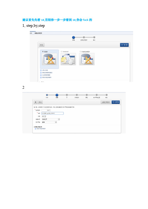
建议首先先看18,否则你一步一步看到18,你会fuck的1, step,by,step234一直下一步5创建成功后,打开sql工作室,创建试图或者表此处用了表:CUX_SLM_QUALIFICATIONSCUX_SLM_ASL_QUALIFICATION下面都是oracle标准表不再附件中MTL_MANUFACTURERShr_all_organization_units视图: CUX_SLM_QUALIFICATIONS_v详细脚本见附件6,创建完成后,点击创建页,7此处选择主从表单8选择你要显示的主表或者视图的字段.9选择从表10,选择主键11,找到2个表之间的关联12选择主表主键序列13,选择从表主键序列14,一路下一步一直到页属性设置标题名:15,设置页签16创建完成,我们来运行下,感觉体验还不够好若点击编辑对应的小图片若点击创建17,接下来在做一些人性化的设置比如form的值列表神马的.找到页3的p_org_id把他做成一个lov,或者列表18,错误,因为之前做的时候都是用的表,没有用view来进行,点击创建后点击保存出现如下错误.这个是因为在做插入的时候是不能直接退视图进行的.但是这个又不像是form.可以写包最终解决办法: 显示的地方sql改为视图的,插入的用基表的,不过不影响前面的文档过程,具体不再贴图,到了个性化在继续贴.只是想体验过程的可以直接用表按上面的过程基本是没有问题的.即选择基表.19,接下来优化20接下来详细报表列:设置asl_id为隐藏,因为此处这个id没有被其他表用到,并赋值为头的QUALIFICATION_ID的值21 生产商low22.设置qulification_type设置flag,没有找到类似checkbox的东西23,此时整体页面呈现效果如下:我们在修改一下标签就更好了点击全部编辑CREATED_BY NUMBER default -1not null,LAST_UPDATED_BY NUMBER default -1not null,LAST_UPDATE_DATE DATE default sysdate not null,LAST_UPDATE_LOGIN NUMBER,ATTRIBUTE_CATEGORY VARCHAR2(30),ATTRIBUTE1 VARCHAR2(240),ATTRIBUTE2 VARCHAR2(240),ATTRIBUTE3 VARCHAR2(240),ATTRIBUTE4 VARCHAR2(240),ATTRIBUTE5 VARCHAR2(240),ATTRIBUTE6 VARCHAR2(240),ATTRIBUTE7 VARCHAR2(240),ATTRIBUTE8 VARCHAR2(240),ATTRIBUTE9 VARCHAR2(240),ATTRIBUTE10 VARCHAR2(240),ATTRIBUTE11 VARCHAR2(240),ATTRIBUTE12 VARCHAR2(240),ATTRIBUTE13 VARCHAR2(240),ATTRIBUTE14 VARCHAR2(240),ATTRIBUTE15 VARCHAR2(240));alter table CUX_SLM_QUALIFICATIONS add constraintCUX_SLM_QUALIFICATIONS_PK primary key (QUALIFICATION_ID);Create Sequence CUX.CUX_SLM_QUALIFICATIONS_S Start With10001;Create Table CUX_SLM_ASL_QUALIFICATION(ASL_QUALIFICATION_ID Number Not Null,ASL_ID Number Not Null,QUALIFICATION_TYPE Varchar2(10) Not Null,MANUFACTURER_ID Number,QUALIFICATION_ID Number,CERTIFICATE_NUMBER Varchar2(100),EXPIRATION_DATE Date,ALERT_LEADTIME Number,EXPIRATION_FLAG Varchar2(1) Default'N',CONTROL_FLAG Varchar2(1) Default'N',DESCRIPTION Varchar2(4000),OBJECT_VERSION_NUMBER Number Default1Not Null,CREATION_DATE DATE default sysdate not null,CREATED_BY NUMBER default -1not null,LAST_UPDATED_BY NUMBER default -1not null,LAST_UPDATE_DATE DATE default sysdate not null,LAST_UPDATE_LOGIN NUMBER,ATTRIBUTE_CATEGORY VARCHAR2(30),ATTRIBUTE1 VARCHAR2(240),ATTRIBUTE2 VARCHAR2(240),ATTRIBUTE3 VARCHAR2(240),ATTRIBUTE4 VARCHAR2(240),ATTRIBUTE5 VARCHAR2(240),ATTRIBUTE6 VARCHAR2(240),ATTRIBUTE7 VARCHAR2(240),ATTRIBUTE8 VARCHAR2(240),ATTRIBUTE9 VARCHAR2(240),ATTRIBUTE10 VARCHAR2(240),ATTRIBUTE11 VARCHAR2(240),ATTRIBUTE12 VARCHAR2(240),ATTRIBUTE13 VARCHAR2(240),ATTRIBUTE14 VARCHAR2(240),ATTRIBUTE15 VARCHAR2(240));alter table CUX_SLM_ASL_QUALIFICATION add constraintCUX_SLM_ASL_QUALIFICATION_PK primary key (ASL_QUALIFICATION_ID); Create Sequence CUX.CUX_SLM_ASL_QUALIFICATION_S Start With10001;。
easyes 常用注解

easyes常用注解EasyES是一个基于Java的快速、简单的Elasticsearch客户端,用于与Elasticsearch进行交互。
在EasyES中,注解是用于配置和指导客户端行为的关键元素。
以下是EasyES中常用的注解及其简要说明:1、Index用于指定索引名称。
例如:Index("my_index") 表示该类对应的Elasticsearch 索引名为"my_index"。
2、Document标记一个类为文档实体,表示该类与 Elasticsearch 中的文档相关联。
可以配置多种属性,如Document(indexName = "my_index", type = "my_type")。
3、Field用于映射实体类属性与 Elasticsearch 字段。
可以指定字段名称、类型等。
例如:Field(name = "field_name", type = FieldType.keyword).4、Mapping用于定义字段级别的映射配置。
可以覆盖默认的字段类型、分析器等。
例如:Mapping(mapping = "{\"field_name\": {\"type\": \"keyword\"}}")。
5、EnableScan开启扫描,让客户端能够自动发现已存在的 Elasticsearch 集群节点。
不指定此注解,则需要手动指定集群节点。
6、ClusterName指定 Elasticsearch 集群名称,用于自动发现时匹配集群节点。
7、Hosts手动指定 Elasticsearch 集群节点地址。
优先级高于自动发现。
8、Routing为文档指定路由值,用于优化查询性能。
9、JsonIgnoreProperties忽略某些属性不进行序列化或反序列化。
TitanG260-300-ds-web

Atomic resolution holography image (upper left) on gold grain boundary using an image Cs-corrector and an X-FEG. The Fourier transformed (upper right) shows sub-Ångström information transfer (arrows).
Cs-corrected HR-TEM image on a filled SWCNT with fullerene structures on the surface of the SWCNT acquired at 60 kV acceleration voltage to
minimize the beam damage. Sample courtesy of Prof. N. Kiselev, Institute
NanoResearch strives to increase our understanding of nanostructures and functional materials by linking the macroscopic material properties to the properties at the smallest level of detail: down to atoms. This continuing drive pushes for the better understanding of local atom organization and for the characterization of atoms, chemical bonding and even the electronic structure. The Titan™ G2 60-300 is the most powerful high resolution scanning transmission electron microscope (S/TEM) with the largest acceleration voltage range of 60 to 300 kV for 2D and 3D material characterization and chemical analysis, down to the atomic level, and delivers the ultimate performance in S/TEM imaging and chemical analysis by allowing the option to combine Cs-correction, a monochromator, and a novel available ultra-stable high brightness electron gun (X-FEG) in one instrument.
web.xmlservlet、servlet-mapping配置

web.xmlservlet、servlet-mapping配置Servlet 常称为服务器端⼩程序,即运⾏在服务器端的程序,⽤于处理及响应客户的请求。
Servlet类是个特殊的java类,继承于HttpServlet。
---------------------------------------------------------------⽅法客户端通常只有GET和POST两种请求⽅式,Servlet为了响应则两种请求,必须重写doGet()和doPost()⽅法。
⼤部分时候,Servlet对于所有的请求响应都是完全⼀样的,此时只需要重写service()⽅法即可响应客户端的所有请求。
另外,HttpServlet还有两个⽅法:(1). init(ServletConfig config):创建Servlet实例时,调⽤该⽅法的初始化Servlet资源。
(2). destroy():销毁Servlet实例时,⾃动调⽤该⽅法的回收资源。
通常⽆需重写init()和destroy()两个⽅法,除⾮需要在初始化Servlet时,完成某些资源初始化的⽅法,才考虑重写init()⽅法,如果重写了init()⽅法,应在重写该⽅法的第⼀⾏调⽤super.init(config),该⽅法将调⽤HttpServlet的init()⽅法。
如果需要在销毁Servlet之前,先完成某些资源的回收,⽐如关闭数据库连接,才需要重写destory⽅法()。
---------------------------------------------------------------Servlet创建时机(1). 客户端第⼀次请求某个Servlet时,系统创建该Servlet的实例,⼤部分Servlet都是这种Servlet。
(2). Web应⽤启动时⽴即创建Servlet实例,即load-on-start Servlet。
---------------------------------------------------------------Servlet的⽣命周期(1). 创建Servlet实例。
去北京旅游的英语日记

去北京旅游的英语日记去北京旅游的英语日记日记即每天所遇到的和所做的事情的记录,有的兼记对这些事情的感受。
每天或经常把发生的`事、处理的事务或观察的东西写下来的记录,尤指个人活动、思考或感觉的每日记录。
下面是收集的去北京旅游的英语日记,希望对您有所帮助!August 2nd is a special day, because 12 of our small partners will represent Jiangxi in the Beijing finals of the eighth session of the special long election campaign. Some small partners were the first to take the train, so they didn't sleep for a long time.On the second day, the grand opening ceremony began. In the opening ceremony, we came to two of the most familiar friends -- Ju Ping, sister and uncle Liuxiaolingtong. We also took a group photo of more than 1000 people.During the match, we were very nervous. Under the encouragement of our teachers and parents, we stood bravely on the stage. Our program, "Snow Mountain and Xiaoba", won the gold medal. Let's not bother our teacher! In order to reward us, Mr. Hu decided to take us to visit Beijing.On the day of the tour, Mr. Hu took us to the Great Wall, Tiananmen, China Science and Technology Museum and the National Grand Theater. My most memorable is the the Badaling Great Wall, the Great Wall and high and long, like a long line on the mountain that is swinging, invisibleleader, and can not see the tail. Especially during the hardships of a journey on the Beacon Tower, the road to climb, my feet are weak. The way down to the Great Wall is more difficult. Some people run all the way down and stop, but some people can't stop. Some people cautiously support the railing on the side and move down step by step. Others even sit on the steps and go down on their butts, which is ridiculous.Although the visit time is very short, but let me feel the ancient and modern of Beijing, let me have a certain understanding of Beijing.Colourful Beijing, I will e back again.After a long wait, I finally came to Beijing. I was with my friend the Yellow Sea and his father. Beijing, a place full of ancient flavour, is also a symbol of modernization.At four a.m., three of us got up and were ready to see the flag. The sky is so dark, the air mixed with the cold air, let me feel terrible. Although it is very early, but people are still a lot, it is probably to see the flag. It was early in the square, and my eyelids were struggling with fatigue. Thousands of thousands of things, and so on, finally wait for 5:20 - the time to raise the flag. A neat team came, their pace was so neat, their voice is so loud, their body is so stiff! I can't help looking at it. Whenthe flag rises, my heart is full of pride and pride. Theflag rose to the top, and the flag raising ceremony was over, but my mood was not pletely calm. The sun went towork and we went back, and I was still looking back on the solemn situation.For the first time in Beijing, we must go to theImperial Palace, Tiantan and the Great Wall, and a magnificent ancient palace. As the tour guide explained, I also walked into a hundred years ago to see the scene of emperor living and dealing with state affairs."Not the the Great Wall is not a good man", I was not a "hero", today I was finally! At Mutianyu, sit on the car went straight to the the Great Wall. Ah! I was stunned by the beauty of my eyes! The fog shrouded mountains, an eagle hovering in the sky, the Great Wall in the fog like shadows, and we play hide and seek. When I climbed the top of the mountain, I was tired and panting. I thought, "ancient people are amazing. On such a steep hillside, the GreatWall is really great. But I still don't know ancient people have acrophobia?After three days of evening, almost to the Beijing classic ancient architecture playing, learned a lot of knowledge, but also made a special trip to visit the Tsinghua University, Peking University, hope to have the opportunity to learn. The trip to Beijing is very short, Iam unable to part, but I believe I will e. Beijing, waitfor me!This summer, mom and dad to exercise my ability to live independently, I hope to participate in Bianliang evening news campus Beijing summer camp activities, I heard that after happy but readily agreed.At nine p. m. on July 27th, I sat in the car, waved farewell to my father and mother, left Kaifeng and set foot on the journey to Beijing.After arriving in Beijing, we went to many places, there is the beautiful scenery of the the Summer Palace, a park like campus, there are fish in the oceans of the world science and Technology Museum Museum, have fun, have not see the end of the the Great Wall, the the Imperial Palace and the beautiful decoration. Among them, the most interesting and interesting places are the aquarium.That day, we went to the aquarium, I saw the fish in the huge transparent water happily swimming, where there are many kinds of sea creatures, all beautifully float in the water, they have electric eels, Moray, jellyfish, sea cucumber, clown fish, sea anemones, coral etc..We are still in the aquarium to see chubby penguins. Penguins walk swaying, like a drunken man, when their swimming speed is very fast, much faster than the speed of goose stroke, it's fantastic.In a short time, we came to the sub sea tunnel. Through the glass, you could see that the big shark on the top was swimming freely. It was really frightening. But from time to time, there will be many colorful little fish swimming around you, as if you are really at the bottom of the sea, which makes you feel very interesting and interesting.I also met a lot of friends at this summer camp. We agreed to grow up to go to university in Beijing.Finally, in the summer vacation, my mother and I decided to go to Beijing to play, which made me happy and I didn't sleep well for a few days. In July 3rd, we embarked on a trip to Beijing.What a lot of historic sites in Beijing! We havevisited the world's largest city square - Tiananmen square, the world's most plete preservation of the Royal Palace, the Imperial Palace, the Royal Mausoleum model -- Ming Dynasty Tombs of Ming Dynasty in Dingling, royal garden, the Summer Palace, visited the Olympic Park in the bird's nest and water cube, the personal experience of the people respected higher Peking University and Tsinghua University the sacred, boarded the majestic the Great Wall, to achieve a "less than the Great Wall of non hero". The beautiful Beidaihe is the last stop of our trip, and Beidaihe is my favorite place.The "character" of the river in Beidaihe is not quite the same in the morning and in the evening. When the tideis back, it will be as gentle and lovable as a rabbit, and when the tide is rising, it will roar like a lion and turn over. You see, how clear the sea is! In the sand grains of the seabed, there are scattered small shells, and they are colorful and countless. Walk in the shallow sea, look, the small shells are all around you "Dancing"! Some of them leaped gently, some stayed in the water and enjoyed the wonderful "performance".And some of my buddies together, TLIDEA sandcastles, pick up shells, play happy. Sometimes we can touchjellyfish and jellyfish in water. We put them in a small bucket, and soon the small bucket is full, and we have a happy smile on our faces.Beautiful Beijing is beautiful! I haven't played enough yet. I'll have to e next time.The summer vacation arrived at last. During the long summer vacation, my mother and I decided to go to Beijing with my two aunts. In August 11th, we embarked on a trip to Beijing.We came to Beijing, found a hotel, put down my luggage, and went straight to Tiananmen. Came to the front of the Tiananmen, I was frightened by the majestic momentum, the middle of the Tiananmen hung our great leader ChairmanMao's portrait, portraits are on both sides of People's Republic of China "long live" and "the unity of the people of the world long live.". The middle of the Tiananmen city building is a glittering national emblem, and the national emblem is eight red lanterns under the national emblem. The magnificent and magnificent Tiananmen is also just like the prosperity of China.From the main entrance of Tiananmen, we came to the Imperial Palace Museum. The Imperial Palace museum is a prehensive museum built on the basis of Ming and Qing Dynasties, the two generation of Imperial Palace and its collection. It before Babel gates, after the Jingshan Hill, Wangfujing in the East and West Zhongnanhai. We approached the the Imperial Palace, the first thing we saw is 5 ancient golden water bridge, we go after the bridge, he saw a magnificent giant building, the Meridian Gate, we sat beside the gate to rest for a while, and then go inside, we saw many weapons and porcelain in the the Imperial Palace, such as knives, guns, swords, bows what. There are bowls, cups. Good things are countless.In the next few days, we went to the beautiful the Summer Palace, the Old Summer Palace of Chinese shame, the cradle of China: Peking University and Tsinghua University, the majestic the Great Wall, and the Museum of the Great Wall and military.In August 17th, we said goodbye to our capital, Beijing!During the summer vacation, my mother took me to travel to Beijing. We visited many famous historic sites, such as the Badaling Great Wall, Beihai Park, the Summer Palace... The scenery is beautiful and spectacular, and the the Imperial Palace is well preserved.At the center of Beijing, there is a city in the city. This is the world - famous Forbidden City and the Imperial Palace. The Forbidden City is the imperial palace of thetwo generations of the Ming and Qing Dynasties. It is the largest and most plete ancient palace plex existing in China, and has a history of more than 500 years. There are four gates in the Forbidden City. The south gate, a shenwumen north, Donghua gate and Xihua gate. The wholecity was rectangular, covers an area of seven hundred and twenty thousand square meters, the size of the palace more than 70, more than 9000 houses. Surrounded by a wall ten meters high, the wall is more than 50 meters wide moat. The walls of the four corners, each with an exquisite ingenious turret. The large size of the the Imperial Palace group is magnificent, the architecture is fine and the layout is unified, which embodies the fine tradition and unique style of the ancient architectural art of our country.What a lot of people to visit the Imperial Palace! The sun in the sky, the ticket hall in front of 3 "long queues"team. We were a foreign tourist in front of us, so we talked with him in my tender English. I first showed my attitude - practising spoken English. He gladly agreed. In the conversation he knew he was a senior math teacher from Turkey. For the first time in China, basically, every city has spent 1 or 2 days. Every time he spent a full 4 days in Beijing, he ended up playing the the Imperial Palace, and took the train at 4 p.m. to Zhengzhou, a holiday. We invite together to visit the the Imperial Palace. Suddenly he thought he was a math teacher, so he asked him. Did the students in Turkey be equally keen on the Olympiad? Guess what the answer is? I tell you the answer is yes. Play for4 hours,...... When he broke up, he gave me a pre - printede - mail address, and we saw it on the Inter.I like this trip. Not only did I enjoy the beautiful scenery, but also I had many opportunities to practice English munication, and I found friends from a foreigner's perspective.This holiday, I finally have a chance to go to Beijing. Beijing is the capital of our country. It was the ancient capital of the past dynasties. There are many places of interest. It is worth savoring. It is still a big city with developed science and technology, which all let my heart look forward to it.I have visited many ancient buildings, of which themost memorable is the the Imperial Palace and the the Great Wall. The Imperial Palace is one of the five famous palaces in the world. It has a large collection of treasures. The palace of the emperor, and Houfei supplies, gold, silver, jade, wood and other products, dizzying. The ImperialPalace let me understand the ancient people's spirit, and can use human power to build such a magnificent palace. One of the seven wonders of the world, the the Great Wall of Wanli is another building embodying the wisdom and strength of the ancient Chinese people. The people also paid a great price. Most of the the Great Wall is built on the mountains, surrounded by trees, and the Beacon Tower rises and falls.It is very spectacular. In the early morning, I look far away on the the Great Wall. I only see a cloud of mist, and I can't see the distance.I'm most interested in visiting Peking University and Tsinghua University. Peking University is very beautiful, I saw the old antique buildings, new buildings in different styles, the famous Weiminghu lake, towering boyata and reflection tower is to add a lot of aura, I linger in the lake...... Tsinghua University is a royal garden site developed, noble and elegant atmosphere. I was in Mr. Zhu Ziqing's "Moonlight" scenery, in a few pieces of lotus pond, green lotus leaf into one, many lotus slim. I think it'sreally a fun thing to learn in such a environment. I want to learn from my older brothers and sisters and be a good student.During the summer vacation, our family went to Beijing for a trip. The purpose is to see the flag raising ceremony and the the Imperial Palace. Especially in the the Imperial Palace, I was attracted to.In the morning, just before dawn, my mother woke me up.I tired, reluctantly out of bed, asked: "how early? What do you call me? " "Alas! Fast, the flag raising ceremony is about to start! " My mother urged me to e down to the door as soon as I got down.Tiananmen square has been a sea of people. We go to the right and go to the right. It's not easy to find a good place. I take out iPad, find the best angle, and get ready to take the best photos.At this time, a team posed of the flag bearers at a vigorous and orderly pace from the golden water bridge into the square. The main bearer will flag on the flagpole on the hook with his flag into the air, the national anthem, the people's Liberation Army soldiers and the military salute, people salute, the bright flag rising to the top of the flagpole in the song, in the morning breeze fluttering in the wind. The solemn and solemn flag raising ceremony was over.Next, we visited the Imperial Palace. The tourists from the Imperial Palace are also the sea of people.The Imperial Palace is so big! It is divided into "before" and "after the house", is said to have nine thousand nine hundred and niy-nine rooms housing. The Meridian Gate, north gate, Donghua gate, Xihua gate is located in the Imperial Palace square.Go for a while, a red huangwa, the magnificent palace in my eyes. It is the "Temple", the emperor of stateaffairs in the morning. Taihe palace of a piece of land, no flowers or grass is not a tree, a piece of light. My mother told me that this is a place to stand zaochao officials. I immediately thought of a scene: the emperor on the one day there, superior officials, listen respectfully the speech, how spectacular! How awesome!"Qing" is the emperor resting place. There areexquisite Kowloon chairs, which symbolize the status of the emperor's noble. There is a coffee table, but also in the approval of the emperor. Walking back, it is "the temple of Thailand", the residence of the queen, and the queen is also enjoying the pleasure here. In the backyard, the small bridges in the garden are full of water and flowers and trees. The Imperial Palace is too big! We traveled from eight a.m. to one in the afternoon to see 1/3 of the wholethe Imperial Palace. It was so tired that we had to leave. How valuable the trip to Beijing is!。
mapping——动态模板

mapping——动态模板Elasticsearch默认给字符类型为text和keyword的混合类型1"type": "text",2"fields": {3"keyword": {4"type": "keyword",5"ignore_above": 2566 }7 }实际业务中,不是所有数据字段都需要进⾏分词的,可以将这部分数据字段的类型设置为keyword类型,需要分词的字段设置为text类型,进⾏分词。
1 PUT user_four2 {3"mappings": {4"aa":{5"dynamic_templates":[6 {7"keyword":{8"match_mapping_type":"string",9"match":"usr_*",10"mapping":{11"type":"keyword"12 }13 }},14 { "text1":{15"match_mapping_type":"string",16"unmatch":"usr_*",17"mapping":{18"type":"text"19 }20 }21 }22 ]23 }24 }25 }PUT user_four/aa/1{"usr_id":"abc","usr_name":"good","address":"北京市昌平区"}GET user_four/_mapping1 {2"user_four": {3"mappings": {4"aa": {5"dynamic_templates": [6 {7"keyword": {8"match": "usr_*",9"match_mapping_type": "string",10"mapping": {11"type": "keyword"12 }13 }14 },15 {16"text1": {17"unmatch": "usr_*",18"match_mapping_type": "string",19"mapping": {20"type": "text"21 }22 }23 }24 ],25"properties": {26"address": {27"type": "text"28 },29"usr_id": { 30"type": "keyword"31 },32"usr_name": { 33"type": "keyword"34 }35 }36 }37 }38 }39 }。
ug440-xilinx-power-estimator

Xilinx Power Estimator User GuideUG440 (v2014.3) October 17, 2014Revision HistoryThe following table shows the revision history for this document.Date Version Revision10/17/20142014.3Revisions to manual for 2014.3 release:•Added links to UltraScale documentation throughout manual.•In Memory Interface Configuration Wizard, page33,and Transceiver ConfigurationWizard, page37, added information about the new entries that will appear indifferent XPE pages when the wizard runs.•Recaptured Figure32, since V CCPINT values have been added to the PLLs table onthe PS Power sheet.06/04/20142014.2Revisions to manual for 2014.2 release:•Changes throughout manual to indicate support for Virtex UltraScale FPGAs in thisrelease of XPE.•Changes throughout manual to indicate that Virtex UltraScale devices may containGTY transceivers.•In Environment section of Settings Panel, added Important Note about how XPEcalculates junction temperature and why XPE’s calculated values may not matchvalues measured on your board system.•Recaptured Figure32, since PS Power sheet now contains two UART rows and twoSD rows.04/23/20142014.1Revisions to manual for 2014.1 release:•Changes throughout manual to indicate support for Kintex UltraScale FPGAs in thisrelease of XPE.•Documented new Manage IP and Snapshot buttons at the top of the Summarysheet.•Documented new Hard IP Block sheet, used to configure 100G Ethernet andInterlaken blocks in UltraScale FPGAs. See Hard IP Block Sheet (UltraScale), page81.•In the Quick Estimate Wizard, you can now specify the Number of physicalInterfaces you will add.•Added new UltraScale power supplies to Table2, page46.•Added additional examples to Using Visual Basic Macros.Table of ContentsUsing Xilinx Power EstimatorIntroduction . . . . . . . . . . . . . . . . . . . . . . . . . . . . . . . . . . . . . . . . . . . . . . . . . . . . . . . . . . . . . . . . . . . . . . 4Getting Started with XPE. . . . . . . . . . . . . . . . . . . . . . . . . . . . . . . . . . . . . . . . . . . . . . . . . . . . . . . . . . . . 5Definitions/Terminology. . . . . . . . . . . . . . . . . . . . . . . . . . . . . . . . . . . . . . . . . . . . . . . . . . . . . . . . . . . . 8User Interface. . . . . . . . . . . . . . . . . . . . . . . . . . . . . . . . . . . . . . . . . . . . . . . . . . . . . . . . . . . . . . . . . . . . 13Exchanging Power Information with XPower Analyzer. . . . . . . . . . . . . . . . . . . . . . . . . . . . . . . . . . . 17Importing Results from Vivado Power Analysis. . . . . . . . . . . . . . . . . . . . . . . . . . . . . . . . . . . . . . . . . 18Data Import and Export. . . . . . . . . . . . . . . . . . . . . . . . . . . . . . . . . . . . . . . . . . . . . . . . . . . . . . . . . . . . 18XPE Wizards (7 Series, Zynq-7000, UltraScale). . . . . . . . . . . . . . . . . . . . . . . . . . . . . . . . . . . . . . . . . . 23Summary Sheet . . . . . . . . . . . . . . . . . . . . . . . . . . . . . . . . . . . . . . . . . . . . . . . . . . . . . . . . . . . . . . . . . . 40Power Comparison Snapshots Sheet (7 Series, Zynq-7000, UltraScale). . . . . . . . . . . . . . . . . . . . . . 49IP Manager Sheet (7 Series, Zynq-7000, and UltraScale Only) . . . . . . . . . . . . . . . . . . . . . . . . . . . . . 54Resource Sheets. . . . . . . . . . . . . . . . . . . . . . . . . . . . . . . . . . . . . . . . . . . . . . . . . . . . . . . . . . . . . . . . . . 57Automating XPE. . . . . . . . . . . . . . . . . . . . . . . . . . . . . . . . . . . . . . . . . . . . . . . . . . . . . . . . . . . . . . . . . . 85Conclusion . . . . . . . . . . . . . . . . . . . . . . . . . . . . . . . . . . . . . . . . . . . . . . . . . . . . . . . . . . . . . . . . . . . . . . 93Appendix A:Additional Resources and Legal NoticesXilinx Resources. . . . . . . . . . . . . . . . . . . . . . . . . . . . . . . . . . . . . . . . . . . . . . . . . . . . . . . . . . . . . . . . . . 94Solution Centers. . . . . . . . . . . . . . . . . . . . . . . . . . . . . . . . . . . . . . . . . . . . . . . . . . . . . . . . . . . . . . . . . . 94References . . . . . . . . . . . . . . . . . . . . . . . . . . . . . . . . . . . . . . . . . . . . . . . . . . . . . . . . . . . . . . . . . . . . . . 94Please Read: Important Legal Notices . . . . . . . . . . . . . . . . . . . . . . . . . . . . . . . . . . . . . . . . . . . . . . . . 96Using Xilinx Power EstimatorIntroductionThe Xilinx Power Estimator (XPE) spreadsheet is a power estimation tool typically used in the pre-design and pre-implementation phases of a project. XPE assists with architecture evaluation, device selection, appropriate power supply components, and thermalmanagement components specific for your application.XPE considers your design’s resource usage, toggle rates, I/O loading, and many otherfactors which it combines with the device models to calculate the estimated powerdistribution. The device models are extracted from measurements, simulation, and/orextrapolation.The accuracy of XPE is dependent on two primary sets of inputs:•Device utilization, component configuration, clock, enable, and toggle rates, and other information you enter into the tool•Device data models integrated into the toolFor accurate estimates of your application, enter realistic information which is as complete as possible. Modeling a certain aspect of the design over conservatively or withoutsufficient knowledge of the design can result in unrealistic estimates. Some techniques to drive the XPE to provide worst-case estimates or typical estimates are discussed in thisdocument.XPE is a pre-implementation tool for use in the early stages of a design cycle or when the RTL description is incomplete. After implementation, the XPower Analyzer (XPA) tool (in the ISE® Design Suite) or Report Power (in the Vivado Design Suite) can be used for moreaccurate estimates and power analysis. For more information about XPA, see the XPower Analyzer Help[Ref1]. For more information about the Vivado power analysis feature, see the Vivado User Guide: Power Analysis and Optimization (UG907) [Ref2].XPE is a spreadsheet, so all Microsoft Excel functionality is fully retained in the writable or unprotected sections of the spreadsheet. XPE has additional functionality oriented towards ease of use. The drop-down menus and the comment-enabled cells are helpful featuresguide you.The XPE spreadsheet also includes the Quick Estimate Wizard, the Memory Interface Configuration Wizard, the Memory Generator Wizard (for block memory and distributed memory), and the Transceiver Configuration Wizard. These wizards help novice and expert users to quickly enter the important configuration parameters, which will then generate relevant lines in the I/O, Logic, Block RAM (BRAM), Transceiver, and Other sheets, helping with accurate power estimation.VIDEO:The Vivado Design Suite QuickTake Video Tutorial: Using the Xilinx Power Estimator shows howthe Xilinx Power Estimator can help you determine power and cooling specifications for All Programmable SoC and FPGA designs early in the product’s design cycle, often even before the logic within the All Programmable SoC or FPGA has been designed.Getting Started with XPEOpening XPE1.XPE requires a licensed version of Microsoft Excel 2003, Microsoft Excel 2007, orMicrosoft Excel 2010 to be installed.Microsoft Excel 2010 is officially supported in this release of XPE.OpenOffice and Google Docs spreadsheet editors are not supported in this release of XPE.2.Download the latest available spreadsheet for your targeted device. The XPEspreadsheets are available at the Power Efficiency webpage.Note:The 7 series/Zynq®-7000 XPE spreadsheet is available in either .xlsm (ExcelMacro-Enabled Workbook) or .xls (Excel 97-2003 Workbook) format.3.Make sure your Microsoft Excel settings allow macro executions. XPE uses severalmacros built into the XPE spreadsheet.°Microsoft Excel 2010 - The following steps are required:a.From the XPE spreadsheet select File > Options.b.In the Excel Options dialog box, click on Trust Center.c.In the Trust Center dialog box, click on Trust Center Settings and select theMacro Settings tab.d.Select Enable all macros, then click OK.e.Reopen the XPE spreadsheet.°Microsoft Excel 2007- The following steps are required:a.From the Microsoft Office button select Excel Options.b.In the Options dialog box, click on Trust Center.c.In the Trust Center dialog box, click on Trust Center Settings and select theMacro Security tab.d.Select Enable all macros, then click OK.e.Open or, if already open, reopen the XPE spreadsheet.Note:The 7 series/Zynq®-7000 XPE spreadsheet is available in either .xlsm (ExcelMacro-Enabled Workbook) or .xls (Excel 97-2003 Workbook) format.content by changing the Trust Center settings is a potentially dangerous way of enabling macro content.an .xlsx file.°Microsoft Excel 2003 - By default, the macro security level is set to High, which disables macros. To change the macro security level, follow these steps (actual menu names will vary with language of Microsoft Excel):a.On the Tools menu, point to Macro and click Security.b.In the Security dialog box, click the Security Level tab.c.Select Medium, then click OK.d.Open or, if already open, reopen the XPE spreadsheet.e.When prompted whether to enable or disable macros, click Enable Macros.Minimum User Input RequiredPower estimation for programmable devices like FPGAs is a complex process, since it is highly dependent on the amount of logic in the design and the configuration of that logic. To produce accurate estimates, the power estimation process requires accurate input values, such as resource utilization, clock rates, and toggle rates. To supply the minimum input that will allow XPE to estimate power with reasonable accuracy, you need the following:• A target device-package-grade combination• A good estimate of resources you expect to use in the design (for example, flip-flops, look-up tables, I/Os, block RAMS, DCMs, etc.)•The clock frequency or frequencies for the design•An estimate of the data toggle rates for the design•The external memory and transceiver based interfaces with their data rates for the design•The thermal environment in which the design will be operatingAs a general rule, input as much information about your design as available, then leave the remaining settings to default values. This strategy will allow you to determine the device power supply and heat dissipation requirements.XPE Calculations and ResultsXPE uses your design and environmental input, then combines this information with the device data model to compute and present an estimated distribution of the power in the targeted device.XPE presents multiple views of the power distribution.•Power by Voltage Supplies - For each required voltage source, this information is useful to select and size power supply components such as regulators, etc. Supply power includes both off-chip and on-chip dissipated power.•Power by User Logic Resources - For each type of user logic in the design, XPE reports the expected power. This allows you to experiment with architecture, resources, and implementation trade-off choices in order to remain within the allotted power budget.•Thermal Power - XPE lets you enter device environment settings and reports thermal properties of the device for your application, such as the expected junctiontemperature. With this information you can evaluate the need for passive or active cooling for your design.The Summary sheet in XPE shows the total power for the device. Other sheets show usage-based power. Leakage within the unused portion of the considered resource (if any) is not shown.Values less than 1mW are displayed as 0.000W. You can copy a cell and paste it into the User sheet to see the actual value with precision adjusted.The following sections provide more details on how to enter settings and review results. Definitions/TerminologySupported Device FamiliesSeparate spreadsheets are available depending on the targeted architecture. These spreadsheets are updated when new device data become available or when new features are added to XPE.•UltraScale™ FPGAs°Kintex® UltraScale°Virtex® UltraScale•7 Series FPGAs and Zynq-7000 AP SoCs°Artix®-7, Artix-7 Automotive grade, and Artix-7 Defense grade°Kintex-7 and Kintex-7 Defense grade°Virtex-7 and Virtex-7 Defense grade°Zynq®-7000, Zynq-7000 Automotive grade, and Zynq-7000 Defense grade •Virtex-6and Virtex-5FPGAs°Virtex-6, Virtex-6 Low Power, and Virtex-6Q Defense grade°Virtex-5, Virtex-5Q Defense grade, and Virtex-5QV Space grade•Virtex-4•Spartan®-6 and Spartan-3A – This spreadsheet includes all sub-families, including Spartan-6 Lower Power, Spartan-6 Automotive, Spartan-6Q Defense-grade,Spartan-3AN, and Spartan-3A DSP•Spartan-3E•Spartan-3Device Model AccuracyThe accuracy of the characterization data existing in the tool is reflected by accuracy designations in the Characterization field on the Summary sheet of XPE. For most FPGAs, the history of the accuracy designation is also displayed in the Release sheet. The accuracy designations are Advance, Preliminary, and Production.AdvanceThe data integrated into XPE with this designation is based primarily on measurements and characterization data made on early production devices. A set of widely used device resources are included in the characterization. Characterization data is limited to these few blocks. This data is typically available within a year of product launch. Although the data with this designation is considered relatively stable and conservative, some under-reporting or over-reporting may occur. Advance data accuracy is considered lower than the Preliminary and Production data.PreliminaryThe data integrated into XPE with this designation is based on complete early production silicon. Almost all the blocks in the device fabric are characterized. Data for most of the dedicated blocks like TEMAC and PCIe block are also characterized and integrated into XPE. The accuracy of power reporting is improved compared to Advance data.ProductionThe data integrated into XPE with this designation is released after enough production silicon of a particular device family member has been characterized to provide full power correlation over numerous production lots. Characterization data for all blocks in the device fabric is included.Total PowerThe total FPGA power is calculated as follows:Total FPGA power = Device Static + Design Static + Design DynamicThe power estimates are modeled to account for temperature and voltage sensitivity. Ambient temperature and regulated voltage on the system can be keyed into the appropriate cells provided for that purpose.Device Static PowerAlso referred to as Leakage. Device static represents the transistor leakage power when the device is powered and not configured.Design Static PowerDesign static represents the additional power consumption when the device is configured but there is no switching activity. It includes static power in I/O DCI terminations, clock managers, etc.For design static power calculations, XPE starts by assuming a blank bitstream. To add your design elements (Logic, I/Os, BRAMs, Clock Managers, etc.) to the design static power calculations, you must enter the resource utilization and configuration in the XPE resource sheets applicable to the design. Any I/O termination should be set to match the board and the design. For any clock managers, enter a small clock frequency in order to indicate usage. Enter or leave clock frequency values 0 on other resource sheets.Design Dynamic PowerDesign dynamic represents the additional power consumption from the user logic utilization and switching activity.Activity RatesXPE shows values for these types of activity rates:•Toggle Rates•Signal RatesToggle RatesProviding accurate toggle rates in the various XPE sheets is essential to get quality power estimates. This information, however, may not be readily available at the stage in the design cycle where you enter data in XPE. Activity may be refined as the design gets more defined. Below are guidelines you can follow to help you enter design toggle activity.•For synchronous paths, toggle rate reflects how often an output changes relative to a given clock input and can be modeled as a percentage between 0–100%. The max data toggle rate of 100% means that the output toggles every active clock edge. Forinstance, consider a free running binary counter with a 100MHz clock. For the Least Significant Bit you would enter 100% in the Toggle Rate column since this bit toggles every rising edge of the clock. For the second bit you would enter 50% since this bit toggles every other rising edge of the clock. When data changes twice per clock cycle, enter 200% for the toggle rate.•For non-periodic or event-driven portions of designs, toggle rates cannot be easily predicted. An effective method of estimating average toggle rates for a given design is to segregate the different sections of the design based on their functionality orhierarchy and estimate the toggle rates for each of the sub-blocks. An average toggle rate can then be arrived at by calculating the average for the entire design or hierarchy.Most logic-intensive designs work at around 12.5% average toggle rate, which is the default toggle rate setting in XPE.It has been observed that designs with random data patterns as input generally have toggle rates between 10%-30%. However, designs with a lot of glitch logic can have toggle rates as high as or even higher than 50%. Glitch logic is generally classified as combinatorial functions which have a high probability of the output changing when any one input changes, such as an XOR gates or unregistered arithmetic logic (i.e. adders).Functions that use large amounts of such logic, such as error detection/correction circuitry, may exhibit higher toggle rates due to this. Designs with large amounts of control path logic, such as embedded designs, on average have lower toggle rates due to large sections of logic being inactive at any given time during operation.In summary, the primary factors that have an appreciable impact on the toggle rate of a design are:°Input data pattern - Random data pattern versus known patterns have an impact on the toggle rate.°Control signals - Use or lack of control signals such as reset and clock enables.°Design logic - High glitch XOR/CARRY logic, a highly pipelined design, or an embedded design have an impact on the toggle rate.modeled at 50% but the synchronizing clock is enabled 50 percent of the time, the resulting toggle rate should be 25% (50% x 50%).designs could possibly have an average toggle rate that high (100%).Note:The IO sheet has a column to specify signal Data Rate. Make sure you adjust the Toggle Rate and Data Rate columns accurately. For example, on an input signal which toggles on both edges of the clock you would enter Toggle Rate = 200% and Data Rate = DDR (Dual Data Rate).Signal RatesSignal rate defines the number of millions of transitions per second (Mtr/s) for the element considered. This is a read-only column that appears on some of the XPE sheets (for example, the Logic, I/O, DSP, and Block RAM sheets). The general equation to calculate signal rate is: Signal Rate (Mtr/s) = Clock Frequency (Mhz) * Effective Toggle Rate (%)FanoutFanout defined in XPE is similar to the fanout reported by the synthesis tool and can differ from the fanout reported by the implementation tool. This difference is expected because fanout will vary with placement and packing of the logic.•In XPE fanout represents the number of individual loads or logic elements the considered element is connected to (LUTs, flip-flops, block RAM, I/O flip-flops,distributed RAM, and shift registers).•In the implementation tool, fanout is the number of SLICEs the considered net is routed to. A SLICE typically contains multiple logic elements and users generally do not control packing of the different elements into SLICEs. XPE algorithms will estimate this packing before calculating the power.Effective ΘJA (C/W)This coefficient defines how power is dissipated from the Xilinx device to the environment (device junction to ambient air). Typically this option is calculated by XPE, taking into account, among other things, the different environment parameters in the Settings panel of the Summary sheet. Entering a value in this field will override XPE calculations. Use this option if you have calculated this parameter by thermal simulations. You may also want to use this feature to factor out environmental parameters when analyzing power differences with another spreadsheet in which environment settings have been set differently.ΘSA (C/W)ΘSA represents the heatsink to ambient air thermal resistance. By default XPE obtains this value from a representative selection of heatsink data matched to the device package, combined with the Heat Sink value you set (Low Profile, Medium Profile, or High Profile) and the Airflow value you set. The value used by XPE is shown in the ΘSA field on the Summary sheet.If you have the ΘSA information for your system you can enter your specific value. First set the Heat Sink drop-down menu on the Summary sheet to Custom, then enter your ΘSA value.ΘJB (C/W)ΘJB represents the device junction to board thermal resistance. By default XPE estimates the junction to board thermal resistance based on standard JEDEC four-layer measurements. If you have done thermal simulations of your system you can enter your own specific value. First set the Board Selection drop-down menu on the Summary sheet to Custom, then enter your ΘJB value.Junction Temperature (°C)This field forces the value of the device junction temperature. XPE then adjusts the ambient temperature to meet the specified junction temperature. This option could be used when you need to work backward from a known or assumed worst case junction temperature and define the environment that would ensure this temperature is not exceeded.User InterfaceXPE has the following sheets:•The Summary sheet lets you enter and edit all device and environment settings. This sheet also displays a summary of the power distribution and provides buttons to import data into XPE, export results, and globally adjust settings.•Other sheets allow you to enter usage and activity details for the different resource types available in the targeted device (for example, IO, Block RAM (BRAM), and Multi-Gigabit Transceivers (MGTs)). These sheets report design power based on the resource usage. Resource leakage power is shown on the Summary sheet.The XPE ToolbarTo make data entry into the tool easier, XPE supports importing data from different sources and allows settings to be changed globally. The toolbar is shown in Figure 2.Note:The toolbar displayed below is the toolbar for the 7 series/Zynq-7000 XPE spreadsheet.Toolbar buttons for earlier architecture spreadsheets may have different names than the names displayed below.Figure 1:Comment Indicators and CommentFigure 2:XPE Toolbar (7 Series/Zynq-7000)Import FileDepending on what stage your design is in the FPGA development cycle, use this dialog box to import design information and activity into the spreadsheet. In the dialog box, select the Files of type field to determine whether you will import an .xls or .xlsm, .mrp, or .xpe file. For a description of the import feature, see Importing Data into XPE, page19.Export FileThe Export File button lets you export the following information from the current spreadsheet:•The current settings for your design within XPE. These settings can be imported into an XPower Analyzer session within the ISE Design Suite.• A text power report, which allows you to analyze the power information in the XPE spreadsheet in a textual format.For a description of the export feature, see Exporting XPE Results, page22.Quick EstimateThe Quick Estimate button opens the Quick Estimate wizard. This wizard is a simple interface to allow novice and expert users to quickly enter the important parameters required for an accurate power analysis of a design implemented in a Xilinx device.For a description of the Quick Estimate wizard, see Quick Estimate Wizard, page24. Manage IPThe Manage IP button opens the IP Manager dialog box, allowing you to run IP Module wizards to easily enter various types of external memory interfaces (e.g. DDR3, DDR3L, LPDDR2, QDR+, RLDRAM), transceiver based interfaces (e.g. 10GBASE-R, Interlaken, PCIe, Aurora, and CPRI), and block memory or distributed memory.For a description of the IP_Manager wizard, see IP Module Wizards, page27. SnapshotThe Snapshot button takes a snapshot of the power status of the current design in the XPE spreadsheet, and places this information on the Snapshot sheet. A snapshot captures the device part, environmental information, the power consumed by your design, and the current across each of the power supply sources used in the design.For a description of Snapshot usage, see Power Comparison Snapshots Sheet (7 Series, Zynq-7000, UltraScale), page49.This button opens up a dialog box which lets you change the default frequency, toggle rates or enable rates for the entire design or for specific sheets (see Figure 3).In the dialog box, default values set by XPE are shown in brackets ([ and ]).The fields in the dialog box are:•Toggle RatesEach field changes activity of the related sheet only. Acceptable range: 0 to 100%.To learn more about toggle rates, refer to Toggle Rates, page 10.•Enable RatesEach field changes activity of the related sheet only. Acceptable range: 0 to 100%.•All Clock NetsThe clock frequency entered here applies to CLOCK, LOGIC, IO, BRAM and DSP sheets.•Output LoadThe equivalent capacitance seen by the output driver for the routing and components connected to this board trace. This setting does not affect power calculations for inputs.Figure 3:Set Default Activity Rates Dialog BoxThe Reset to Defaults button resets all user settings to their default values, except for values in the Device selection table on the Summary sheet, and deletes all user entered values on the block details sheets (Clock, Logic, etc.).XPE Cell Color-Coding SchemeTo simplify data entry and review, the XPE cells are color coded. A color Legend appears at the bottom of the Summary sheet (see Figure 4).A description of the spreadsheet’s color-coding scheme is provided in Table 1.Figure 4:Color Legend (Summary Sheet)Table 1:XPE Cell Color-Coding SchemeCell Color Cell UseAvailable User ActionWhite Allows user to enter data Editable Grey Displays a calculated value Read-only Green Displays a summary valueRead-only Blue User override of cells normally calculated by XPE Editable OrangeFlags a warning. Indicates that a resource is not available.EditableRed Flags an error.Examples of errors are:•A resource limit in the device has been exceeded.•The limits of a device specification (for example, junction temperature) have been exceeded.Read-only. Edit other cells to correct the error.。
STEPBYSTEP使用MOTIONANALYZER进行运动控制项目选型

STEP BY STEP使用MOTION ANALYZER 进行运动控制项目选型REVISION: 1.1GOTC 李金贤罗克韦尔自动化(中国)有限公司目录1 Step 1: 启动Motion Analyzer (3)2 Step 2: 选定驱动器的产品系列(product family) (3)3 Step 3: 进入运动参数输入 (5)4 Step 4: 轴基本参数设定 (6)5 Step 5: 运动曲线的编辑 (7)6 Step 6: 机械参数设定 (15)7 Step 7: 传动参数设定 (19)8 Step 8: 开始选型 (20)9 Step 9: 选型完成 (28)10 Step 10: 产生最终的报表 (32)1 Step 1: 启动Motion Analyzer如果您已经完成了MOTION ANALYZER的安装,您可以在WINDOWS的开始菜单启动MOTION ANALYZER.2 Step 2: 选定驱动器的产品系列(product family)完成启动MA后,默认的界面如下图:如果你的MA界面变成以下界面:表示你处于“经验式”选型模式,这种选型模式是根据电机的转速、扭拒以及功率等进行型号选定。
如果你需要进入“数据分析式”选型模式,你可以点击下图红框所示的按钮。
进入了“数据分析式”选型模式,我们先确定使用哪一种驱动器产品系列,在下图中鼠标左键点击PRODUCT FAMILY右边的下列框,选定我们要选型的驱动器产品系列。
可以看到MA不仅可以在伺服驱动器当中进行选型,也可以在变频器系列的产品中进行选型。
3 Step 3: 进入运动参数输入入下图红色框所示按钮,鼠标左键点击进入。
将会进入以下界面:我们以下将逐项解释每个页面将会涉及哪些选项的设定:4 Step 4: 轴基本参数设定在“Axis Setup”页面,有以下参数需要进行配置:(请看中文解释)我们必须进行设定的参数有:直线还是旋转的运动;电压是单相的还是三相;电压大小是多少;其他的一般都不需要进行设定(使用默认的即可)。
Quark

Working with Quark® Xpress Compatible with versions 5, 6 and 7Quark Xpress® Using this GuideUse This GuideThis guide is designed to be used as a hands-on tutorial. It provides an overview of basic Quark features. This guide may be used time and time again as a technical resource for each issue of your publication throughout the year.Tech Know LessonsJS Printing’s Tech Know Lessons are step-by-step instructional guides that are software specific. These lessons cover common topics for your design program. Tech Know lessons are available via . Please note that you must be logged in to your JSP account to access this feature.Personal HelpWe are here to help you every step of the way. Call your friendly, knowledgeable Customer Service Representative wheneveryou have a question about software or printing issues: 866-HELP-JSP (866-435-7577).are networked,folder where all the folder on each folder that has all theQuark Xpress® Toolbar and Palettes OverviewMeasurements PaletteText SelectedObject SelectedLeadingSpacing between lines of type TrackingSpacing between lettersFont SizeChoose Font Style HereCoordinate values of an object’s position on the pageSizing Option:width and height of selected objectAngle of object boxSize of content in boxPosition of content inside boxSkew of content in boxAngle ofcontent in boxShape of object box Number of columnsTool BoxA Item tool: Select, move and resize objects.B C ontent tool: Manipulate the content of object boxes (text and graphics).C Rotate tool: Select and rotate objects.D Z oom tool: Magnify or reduce an area of the page.E T ext box tool: Draw text boxes of whichever shape you choose from the pull-out menu.F P icture box tool: Draw picture boxes of whichever shape you choose from the pull-out menu.G T ables tool: Draw tables.H O rthogonal Line tool: Creates straight Horizontal and Vertical lines I L ine-text path tool: Put text along a straight, freeform or bezier line.J L inking tool: Connect text boxes for jumps. K U nlinking tool: Break the connection between linked boxes.L Composition Zones tool (Quark 7 only): Create a composition zone M C utting tool: Cut the boundary of items. N S tarburst tool: Draw starbursts.AB C F E D G H I J K M NTIP: If your palettes are not visible, you can activate them by selecting one of the following: View > Show Tools orView > Show Measurements or View > Show ColorsLQuark Xpress® Creating a Publication1) Open Quark and go to File>New >Project .2) - Put a check mark in the Facing Pages box- Choose the page size from the drop-down menu. - For newsprint, select Tabloid - For non-newsprint, enter the size of the desired publication in the width and height fields- In the Number field, choose the number of columns that you want the document to have. - Make all margins .5”.- Indicate the number of columns that you would like. - Click OK . - This will create a one page document.Building your pages to JS Printing specifications3) To add pages, choose Page>Insert.4) Type in the number of pages that you need to add in the Insert field.- E.g. type in 7 for an 8 page paper.5) Select After 1.6) Click OKQuark Xpress® Getting Started with TextAbout TextAll text in QuarkXPress is contained either in text boxes or text lines. When you click a text object with the Item tool, the text object's border is displayed. A text object can be moved, resized or threaded to other text objects.Text Boxes• A re created by clicking the Text tool, then clicking and dragging to the desiredsize.• C an be moved or resized with the item tool.• C an be linked together to create jumps.TIP: An empty text box’s edge will appear onscreen as a dotted line as long asView > Show Guides is selected.Creating a Text Box- Select the Text Box tool and the shape you want. Click and drag on the page todraw the box. Select the Content tool to begin typing.Resizing the Box or Frame- A djust the size of the box or frame by choosing the Item tool and dragging oneof the handles.or- Use the Measurements palette. To adjust the frame or box to the size that youwant, type directly over the existing numbers in the width and height fields.Width and height ofselected objectQuark Xpress® Placing and Linking TextPlacing Text1) W ith the Item tool, click on the text box.2) Select File > Import Text.3) B rowse to the article that you want to place.4) Select the article and click Open.TIP: All articles should be saved in .txt format.Typing TextSelect the Content tool. Click inside the text box in which you wish to type. Starttyping.Linking Text BoxesConnecting text blocks together (linking) allows you to easily flow text from one page to another. You can link text boxes whether or not they contain text.To link text from one box to another:1) W ith the Item tool selected, click on a text box or frame.2) Click the Link tool.3) Click the box again, then click on the text box to which you want to link it.4) C lick another text box.5) T he boxes are now linked.Choose Text Alignment1) Highlight the text you want to align.2) Select Style > Alignment3) Select the alignment you want.or1) Highlight the text2) Select the appropriate alignment icon in the Measurements palette.Setting Indents1) Highlight the text for which you want to set theindent.2) Select Style > Formats3) In the appropriate indent field, indicate the sizeindent you would like.4) Click OK.Changing Leading1) Highlight the text that you want to change.2) In the Measurements palette, adjust the leading by using the arrows or by typing in the desired space.- If your measurements palette is not visible, select Window>Measurements.Quark Xpress® Formatting TextChanging Fonts1) Highlight the text that you want to change.2) In the Measurements palette, choose the font that you would like to use from the drop-down menu.- If your measurements palette is not visible, select Window>Measurements.- If you want to bold or italicize your font, be sure to use the printer font and not the screen font, e.g. if you want the bold version of Times New Roman, select the font named Times New Roman Bold from the drop-down menu instead of using the bold feature on the measurements palette.Changing Font Size1) Highlight the text that you want to change.2) In the Measurements palette, choose the font size that you would like to use from the drop-down menu or type the size that you want in the font size field..- If your measurements palette is not visible, select Window>Measurements.LeadingSpacing between lines of typeFont SizeChoose Font Style HereMeasurements PaletteSize and Crop the Image in Photoshop1) O pen Photoshop. Select File > Open and browse to the image that you want to place on the page.2) D ouble click on the Crop tool. This will bring up the Cropping Tool Options. Depending on which version of Photoshop you are using, you will see one of these windows.3) Enter in the Width and Height of the image box that is drawn off in InDesign.4 W ith the Crop tool still selected, drag a box around the area of the image that you wish to keep.5) W hen you have the desired area selected, press Enter or double click inside the box. The part of the image outside the selected area will be deleted and you willbe left with the image in the dimensions you entered.TIP: If you do not see the Crop tool, click and hold to reveal more tools.Photoshop 7, CS, CS2, CS3 and Photoshop ElementsPhotoshop 4, 5, 6 and Photoshop LE(Select Fixed Target Size)IMPORTANTPlease refer to the Help section of your image editing program if you are notusing PhotoShop to edit your images.- When you name the images, include the page number in the name. Example: “1-football.tif” would be on page 1. That way, all images will have a unique name and you can easily tell where they go.WARNING: You can not have two images with the same name. If you place two images with the same name in the file, then when our pre-press techs relink the images, the same image will link to both frames. Saving all images used in the paper in the Issue folder will prevent this because you can not have two files with the same name in one location.Drawing an Image Box1) Select the Picture Box tool- You can select different shapes for your picture box by clicking once and holding the left-mouse button on the Picture Box tool.2) In your document, click and hold the left mouse button and draw a box the appropriate size.Determine Image Size1) Click on the picture box with the Item tool.2) In the Measurement Palette check the height andwidth of the box. Write these sizes down.Width and height of selected object(A picture may appear to be Grayscale but you should always check the Mode to be sure.)Save the PictureA) Select File > Save As.B) Browse to where you want to save the image.C) Name the file a unique name.D) Choose format .tif from the format drop-down menu.E) Click Save.IMPORTANT: Do not change the name of an image after it has been placed on the page. This will break the link.TIP: If you see a screen asking for Compression Type, choose None .TIP: If you can not select “.tif,” go to Layer > Flatten Image, then Save and select “tif.”Change the Mode to CMYK for Color ImagesImages for non-newsprint publications can print in black and white or full color. Open the image in PhotoShop and select Image > Mode > CMYK (A picture may appear to be color but you should always check the Mode to be sure.)Change the DPIOpen the image in PhotoShop and select Image > Image Size.In the Resolution field (resolution is the same thing as DPI), please enter the following:For newsprint: 130 for pictures and 600 for line art or clipart. For non-newsprint: 200 dpi for pictures and 600 for line art or clipart.Change the Mode to Bitmap for ClipArt and Line Art ImagesOpen the artwork in PhotoShop and select Image > Mode > Bitmap.Quark Xpress® Placing ImagesPlace the Picture into Your Document1) S elect File > Get Picture (File>Import Picture for Quark 7 users).2) B rowse to find the image that you want to place.3) Select the picture.4) Click Open.Non-newsprint publications only - If you would like your content to bleed off the page, simply extend the content off the page by 1/8th” (.125). Select the Picture FrameIn your Quark document, select the picture frame with the Content tool.Once the images have been placed on the page, Quark 7 users can change the images to Grayscale Mode or CMYK Mode.1) Using the selection tool, choose File>Save Picture>All Pictures in Layout.- F rom the color mode menu select: Grayscale- C hoose Link Layout to New Picture and click OK- Choose Highest in the .JPG options window and choose None in the .tif options window, click OK.- Browse to where your original image files are saved and choose OK.Quark 7 usersQuark Xpress® Using Spot Color and Screens Apply Color to Text1) Select View > Show colors (Window>Colors in Quark 7).2) Highlight the text that you would like to be in spot color with the Content tool.3) S elect Cyan in the color palette.4) Y ou can change how dark the color prints by changing the percentage in the drop down menu, or typing directly over the numbers.Apply a Fill and FrameA frame is the equivalant to a border.1) To create a frame, select the box to which you would like to apply a frame.2) Select Item>Frame.- Choose what point size you want from the drop-down menu or type the size that you want in the field. Click OK.1) To fill a box with color, select the Fill tool on the Colors palette.2) Choose the color that you want.- The only colors that you should use in your document are shades of Cyan and Black.TIP: The only colors that should be used in your document are Black, None, Paper and Cyan. See our Tech Know lesson: Working with Spot Color for more information on how to use spot color.Quark 7 users have the option to change the Opacity of the image.1) To change the opacity of an image, select the image.2) In the Opacity field of the Colors palette, select the desired opacity from the drop-down menu or type the opacity into the field.Quark Xpress® PDF your file1) Select File>Print.2) In the printer pull down menu,choose Adobe PDF.For non-newsprint orders withbleeds, select the Bleed tab from thelist to the left and select Asymmetricand fill in the correct bleed value(.125”) for each side of the page. Checkthe box next to Clip at Bleed Edge. Thiswill obtain the bleed settings from theQuarkXPress document in the createdPDF.3) Choose Properties4) From the Adobe PDF Page Sizepull down menu, select Tabloid.5) Click on the Edit button beside theDefault Settings pull down menu.6) Select the Fonts tab. Select EmbedAll Fonts and click OK.7) C lick O K i n t he A dobe P DF D ocumentProperties Window.8) Select the Setup tab and chooseGeneric Color from the PrinterDescription menu. This step isnecessary only if you are planning tohave spot color in your document.9) Click Print and choose where youwould like to save the PDF. ClickSave.124568 Creating a PDFQuark 7 users: Please see next page.。
iBATIS step by step

iBATIS step by step (1)出处:责任编辑:sdq[04-4-6 14:27] 作者:Argan Matrix 今天抽空写了step by step的 step 1,首先用了一个最简单的例子来说明iBATIS 的灵活与方便.一些说明,1.例子使用eclipse进行开发,所以附件的包里有eclipse的.classpath和.project文件,为了简单清晰,我尽量简化了相关的配置2.附件带有所有需要的jar并在win2k+jdk1.4.2和fedora core 1 + jdk1.4.2上测试通过下面正式开始....首先建立一个简单的bean:Account然后写一个xml文件,就是sql mapping的配置了,比如叫Account.xml这样我们需要的和业务相关的配置就这么多了,在程序里面,我们就可以进行使用了当然,我们还需要一些关于数据库的配置,比较简单:这个配置文件其实是相当于sql map的一个总控配置,我们读取配置的入口就在这里了,iBATIS提供了非常方便的读取方式:基本上,我们需要做的就这些了,做好这些工作之后,我们就可以写一个方法来进行测试了,这时候,你可以试试改变一下配置文件里的sql语句,再运行一下,可以轻松体验一下iBATIS的强大与灵活了.这一节里,使用了一个实际的例子来说明dynamic-mapped-statement 和 insert 的简单使用.系统发布后一段时间,对系统留下的一些log,特别是所执行的sql语句进行分析,来获取用户使用习惯的第一手数据,以便以后我们的改进。
今天就做了这样一次简单的分析,由于系统中几乎所有的查询都使用我的一个统一的借口来进行查询,所以SQL的log有统一的标志,收集起来相对容易。
下面一步一步的描述一下整个过程:一、搜集log1. 从服务器上获取log文件,无需多说2. 用程序分析log,并将sql解析出来,做一些处理,保存到数据库中。
EES软件教程EEStutorial
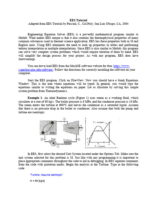
EES TutorialAdapted from EES Tutorial by Pascual, C., Cal Poly, San Luis Obispo, CA, 2004Engineering Equation Solver (EES) is a powerful mathematical program similar to Matlab. What makes EES unique is that it also contains the thermophysical properties of many common substances used in thermal science application. EES has these properties both in SI and English units. Using EES eliminates the need to look up properties in tables and performing tedious interpolation or multiple interpolations. Since EES is also similar to Matlab, this program can solve very complex system problems which would require iteration if done by hand. EES will simplify the design process for your project. As with any program, EES does have shortcomings.You can down load EES from the MechSE software website for free: https://www-/software/. Follow the directions for correctly installing the software on your computer.Start the EES program. Click on File>New. Now you should have a blank Equations Window. This is the area where equations will be typed. In general, you would type the equations similar to writing the equations on paper. Let us illustrate by solving this simple system problem from Thermodynamics.Example 1: An ideal Rankine cycle (Figure 1) uses steam as a working fluid, which circulates at a rate of 80 kg/s. The boiler pressure is 6 MPa, and the condenser pressure is 10 kPa. The steam enters the turbine at 600°C and leaves the condenser as a saturated liquid. Assume that there is no pressure drop in the boiler or condenser. Also assume that both the pump and turbine are isentropic.In EES, first select the desired Unit System located under the Options Tab. Make sure the unit system selected for this problem is SI. Just like with any programming it is important to place appropriate comments throughout the code to aid in debugging. In EES separate comments from the code with quotation marks. Begin the analysis at the Turbine. Type in the following code:"Turbine: Assume isentropic"m = 80 [kg/s]P_boiler = 6000 [kPa]T_3 = 600 [C]h_3 = enthalpy(steam, P=P_boiler, T=T_3)s_3 = entropy(steam, P=P_boiler, T=T_3)P_condenser = 10 [kPa]h_4 = enthalpy(steam, P=P_condenser, s=s_3)W_turbine = m*(h_3-h_4) "[kW]"EES has the ability to check units for you but conversion factors must be used and all variables must be assigned a unit. Above, by placing the units for the variables in brackets ([kPa]), you are assigning units to this variable. In the solution window, this unit will appear next to the variable. This type of assignment only works when a variable is assigned a numeric value like P_boiler. You will notice that next to W_turbine, the units are typed as "[kW]". In this situation, the units have not been assigned to the variable because EES does not know which variable in that equation has units of kW. Therefore, to properly assign units to W_turbine, highlight the variable W turbine and right click the mouse. Choose Variable Info. Enter units as kW.The underscore symbol (like h_4) is used to denote a subscript. Therefore, in the Formatted Equation window the variable h_4 will appear as h_4. Go to the Windows tab and select Formatted Equations. Another window will open showing the equations in a neat printable form.You do not have to remember the format for the property equations. Instead go to the Options tab and select Function Info. From here select Fluid Properties. The box on the left shows the property, while the box on the right shows the fluid. Instead of typing the equation, choose enthalpy and steam and then paste (Do not do this now since you already typed in the equation above). Remember from the State Postulate, that you need two independent properties to define the state. The function information shows pressure and temperature, but you can choose any two independent properties. In setting the enthalpy at state 4, notice that pressure and entropy were chosen. Now type the following code for the remainder of the system components."Condenser: Assume no pressure drop"h_1 = enthalpy(steam, P = P_condenser, x = 0) "Aside: Recall x is the quality"s_1 = entropy(steam, P =P_condenser, x = 0)Q_condenser = m*(h_1 - h_4) "[kW]""Pump: Assume isentropic"h_2 = enthalpy(steam, P= P_boiler, s = s_1)W_pump = m*(h_1 - h_2) "[kW]""Boiler: Assume no pressure drop"Q_boiler = m*(h_3-h_2) "[kW]""efficiency"eta = (W_turbine+W_pump)/Q_boiler "[-]"EES does not recognize the difference between lower and upper case letters; therefore, variables q and Q are interpreted as the same variable. Greek letters are entered by typing their full name like eta for 11. In the Formatted Equations, Greek letters appear as their symbol. Finally, has no units and that is indicated by [-] next to the variable. Don't forget to add units to Q_condenser, W_pump, Q_boiler, and eta.Now that the code has been entered, the system of equations can be solved. Before solving the equation, check for any syntax errors by clicking on Check/Format under the Calculate tab (or by pushing the red check button). If no errors are found, this check will inform you of the number of equations and the number of unknowns. If the number of equations and number of unknowns are not equal, no solution can be found. If the format is correct, then click on Solve also under the Calculate tab (or by clicking the calculator button). The solution window will appear showing the values for all the variables. EES will also perform a units check. Click Check Units under the Calculate tab. You will notice that the properties have units automatically added. The answers for the first exercise are: W turbine= 110990 kW, Q condenser= -166318 kW, W pump = -483.5 kW, Q boil =276825 kW, and 0.3992.Clicking Print under the File tab will print the program and solution. The formatted equations choice will print out the equations in a format similar to written equations. Another powerful feature of EES is the Parametric Table. This feature allows you to vary parameters and see the result on the system. This feature will be very useful in your design project when choosing the best overall design. This feature will be illustrated with the following example.Example 2: The condenser pressure from Example 1 is now allowed to vary from 2 kPa to 10 kPa. How does varying condenser pressure affect the power from the turbine and the efficiency of the cycle?Click on New Parametric Table under the Tables tab. For this example, choose 9 runs, and title the table as Condenser Pressure. The left box shows all the variables in the program. Choose P_condenser first. Click Add. Now P_condenser is removed from the left box and placed in the right box. Next addW_turbine and eta to the box on the right and click OK. A spreadsheet looking table now appears withP condenser, W turbine, and appearing at the top. On the column for P condenser, click on the black arrow at the top. Set the first value to 10 and the last value to 2 (therefore, the pressure will vary from 10 kPa to 2 kPa in 1 kPa increments) and click OK. EES will now fill in the column of P condenser with the test values. EESwill now solve the program for each value of P condenser and insert the corresponding values of W turbine and in the appropriate column. To solve the table either click the green arrow in the upper left or click Solve Table under the Calculate Tab. To avoid an error in solving the table, the equation, which sets the value for P condenser, must be deleted in the Equations window. Therefore there is one variable more than the number of equations.As the condenser pressure drops, the power from the turbine and the cycle efficiency increase. You can plot this trend by clicking New Plot Window (X-Y Plot) under the Plots tab. Choose P_condenser for the x-axis and W_turbine for the y-axis. Before clicking OK, check the automatic update box, so the graph will be updated every time the table is updated. The plot can be resized by dragging the lower right hand corner. Now add the efficiency data by clicking Overlay Plot under the Plots tab. Select eta for the y-axis and select Y2 for the right Y-scale. Don't forget to click automatic update before hitting OK. Your graph should look similar to Figure 2. If it doesn't look similar to Figure 2 then adjust the y-axis scales. There are many features which are similar to Excel, which allow you to change the format of the plot and addt ext. Now let us do another example, which is more difficult.Figure 3. Rankine Cycle with RegenerationExample 3: The ideal Rankine cycle described in Example 1 is modified to include the regeneration process. A portion of the steam is extracted from the high-pressure turbine at 0.5 MPa and is used to heat the feedwater in an open feedwater heater (Figure 3). The rest of the steam enters the condenser at 10 kPa. All other conditions are the same as Example I. You may assume that both pumps and the turbine are isentropic. The open feedwater heater is at saturation conditions with a pressure of 0.5 MPa. Here is the program to solve this example. Start with a new equation window."Turbine: Assume isentropic"m = 80 [kg/s]P_boiler = 6000 [kPa]T_5=600 [C]h_5 = enthalpy(steam, T = T_5,P = P_boiler)s_5 =entropy(steam, T= T_5, P= P_boiler)P_condenser = 10 [kPa]h_7 = enthalpy(steam, P = P_condenser, s = s_5)T_7 = temperature(steam, P = P_condenser, s = s_5)h_6 = enthalpy(steam, P = 500, s = s_5)m_7 = m - m_6 "Mass Balance"W_turbine = m*h_5 - m_6*h_6 - m_7*h_7 "[kW]""Condenser: Assume no pressure drop"h_1 = enthalpy(steam, P = P_condenser, x = 0)s_1 = entropy(steam, P = P_condenser, x = 0)Q_condenser = m_7*(h_1 -h_7) "[kW]""Low-Pressure Pump: Assume isentropic"h_2 = enthalpy(steam, P = 500, s = s_1)W_lowpump = m_7*(h_1 -h_2) "[kW]""Feedwater Heater: Assume saturated system"h_3 = enthalpy(steam, P = 500, x = 0) "Saturated liquid at exit of feedwater heater"s_3 = entropy(steam, P = 500, x = 0)m_6 = (m*h_3 -m_7*h_2)/h_6 "[kg/s]""High-Pressure Pump: Assume isentropic"h_4 = enthalpy(steam, P = P_boiler, s = s_3)W_highpump = m*(h_3 - h_4) "[kW]""Boiler: Assume no pressure drop"Q_boiler = m*(h_5 -h_4) "[kW]""Efficiency"eta = (W_turbine + W_lowpump + W_highpump)/Q_boiler "[-]"Don't forget to add units to the following variables: m_6, m_7, W_turbine, Q_condenser, W_lowpump, W_highpump, Q_boiler, and eta. After typing in the program, check the format and solve the equations. As you will see, the solution is solved iteratively since the mass flowrate to the feedwater heater was not known. However, EES was able to solve the problem. This is not always the case. Sometimes EES needs help. The next example will illustrate this point. The solution for Example 3 is: W turbine = 102581 kW, Q condenser = -138875 kW, W lowpump = -33 kW,W highpump = -480 kW, Q boiler = 240943 kW, = 0.4236.Example 4: A 25-mm diameter cable has an electrical resistance of 10-4 /m and istransmitting a current of 1000 A. If the cable is submerged in a tank of water at 1°C and is flowing at 5 m/s in cross flow over the cable, what is its surface temperature in °C?From Newton ’s Law of Cooling, the heat transfer from the cable per unit length is:)('T T h D q s . Solving for the surface temperature: h D q T T s '. The properties of thefluid need to be evaluated at the film temperature: )(5.0T T T s film . As you will learn in heat transfer, these types of problems require iteration on the fluid properties since the filmtemperature is unknown. EES now makes this part easier (almost). The Hilpert correlation is used to calculate the heat transfer coefficient from a heated cylinder. Here is the program to solve this example. Start with a new equation window."Heat Transfer Rate"q = 1000^2*10^(-4)"Heat Transfer Coefficient"T_0 = 10 [C]T_film = 0.5*(T_0+T_surf) "[C]"Nu = VISCOSITY(water, T=T_film, P=101.32)/DENSITY(Water, T=T_film, P=101.32)V = 5 [m/s]D = 0.025 [m]Re_D =V*D/nu "[-]"Pr = PRANDTL(Water, T=T_film, P=101.32)NuD = 0.193*Re_D^0.618*Pr^(1/3) "[-] Hilpert Correlation"k = CONDUCTIVITY(Water, T=T_film, P=101.32)h = NuD*k/D "[W/m^2-C]""Surface Temperature"T_surf = T_0 + q/(pi*h*D)After checking the format of the equations, adding units to variables and correcting any syntax errors, click calculate. More than likely, EES will give you some type of error, which does not result in a solution. This error is not a result of a programming mistake, but instead it is a mistake in your initial guesses. Click on Variable Info under the Options tab. This screen will show you all the variables, their initial guess, their lower limit, their upper limit, and their units. The default values are negative infinity for the lower limit, positive infinity for the upper limit, and an initial guess of 1. For this example, these particular limits and guess are not working so you need to change them. In order to come up with intelligent guesses, you need to know how the system is behaving. In this example not knowing the film temperature is causing the properties to be poorly guessed. Therefore replace the equation for the film temperature with T_film=10°C and solve the problem. Now you have a solution, which is not correct but it is better than no solution. Use this solution to update the guesses in the Variable Info window and resolve the problem by putting the original equation for T_film back into the program. The answers are T surf = 10.1 °C and T film = IO.06°C.。
EELS mapping step-by-step

30
36.Select the signal with the energy window tool
31
37. In Unary processes, click on Extract Map/Profile
32
38. Double click on the map and in the Image/Display Properties dialog window change Name and Style as wished
26
31. To map an element, click on the Energy Window Tool 32. Select a window for background: typically, larger than signal window and about 5eV before the edge
17
20. In Experiments > Settings, define the experiment’s conditions
18
21. press 'Add markers' and position the map box (orange) and the drift correction box (y (yellow) )
45
53. In Quantify tab, click on Quantify 54. Select parent spectrum-image; click OK; click OK
46
55. Select Window > Floating Windows > Color Mix
47
55. Select Window > Floating Windows > Color Mix
《网络规划与优化》电子教案 单元二

上一页 下一页 返回
任务2.1 生成树配置
• 2.1.3 STP工作原理
• STP主要思想就是当网络中存在备份链路时,只允许主链路激活,如果 主链路因故障而被断开后,备用链路自动打开。IEEE802.1d生成树协 议检测到网络上存在环路时,自动断开环路链路。当交换机间存在多 条链路时,交换机的生成树算法只启动最主要的一条链路,而将其他链 路都阻塞,将这些链路变为备用链路。当主链路出现问题时,生成树协 议将自动启用备份链路取代主链路工作,不需要人工操作。那么,STP 又是如何实现该功能的呢? 下面通过生成树协议的工作过程来了解 STP是如何实现的。
上一页 下一页 返回
任务2.1 生成树配置
• 3)端口ID最小。 • 根路径成本:某个交换机到达根交换机的中间所有链路的路径成本之
和,如图2.1.6所示。 • 一条链路的路径成本与带宽有很大关系,一般带宽越宽的链路路径成
本越小。具体带宽与链路路径成本对应关系如表2.1.1所示。 • 端口ID由端口优先级和端口编号组成,如图2.1.7所示。 • 根据根端口选择依据,图2.1.4中选中的根端口如图2.1.8所示。 • 非根交换机SB、SC上标有○的端口被选择为根端口。 • ◎选择指定端口。
• 2.1.2 STP作用
• 生成树协议最主要的应用是为了避免局域网中的单点故障、网络回环 ,解决成环以太网网络的“广播风暴”问题,从某种意义上说是一种网 络保护技术,可以消除由于失误或者意外带来的循环连接。STP也提 供了为网络提供备份连接的可能。STP主要作用体现在以下两方面。
• ◎解决环型网络引起的广播风暴、帧复制及MAC地址表的不稳定等 问题;
上一页 下一页 返回
env.step 用法 -回复

env.step 用法-回复`env.step` 是一个在机器学习中常用的函数,用于执行一个动作并返回与之相关的信息。
它通常在强化学习任务中使用,其中智能体需要根据当前的状态选择一个动作来使得环境的状态发生变化。
本文将详细介绍`env.step` 的用法,并解释每个步骤的作用和返回值的含义。
1. 准备环境和智能体在使用`env.step` 之前,我们需要准备一个环境和一个智能体。
环境是模拟我们希望智能体解决的问题或任务的虚拟世界,而智能体是我们希望能够从环境中学习和表现良好的实体。
通常,我们可以使用开源库`gym` 来搭建环境,例如:pythonimport gymenv = gym.make('CartPole-v1')在这个例子中,我们创建了一个名为`CartPole-v1` 的环境,其目标是通过控制一个摆杆上的小车,保持摆杆的平衡。
2. 执行一个动作一旦环境和智能体准备就绪,我们可以使用`env.step` 执行一个动作。
这个动作是智能体根据当前状态选择的,并传递给环境进行执行。
例如,在CartPole 环境中,智能体可以选择向左或向右施加一个力来控制小车的运动。
执行一个动作的代码如下:pythonaction = 1 # 选择动作1,向右施加力observation, reward, done, info = env.step(action)在这个例子中,我们选择了动作1,向右施加力。
`env.step` 的返回值是一个包含四个元素的元组,分别是:- `observation`:新的观测状态,即执行动作后环境的新状态;- `reward`:动作的奖励,用来评价动作的好坏。
数值越高越好;- `done`:一个布尔值,指示任务是否已经结束。
通常当摆杆倾斜太多或小车离开轨道时,任务会被认为结束;- `info`:一个包含其他额外信息的字典,用于调试和分析。
3. 迭代执行动作一般来说,在强化学习任务中,我们会迭代执行动作并不断更新智能体的策略,以使其在环境中表现更好。
制作香烤鳗鱼英语作文

制作香烤鳗鱼英语作文Making Grilled Eel English CompositionGrilled eel, also known as "Unagi," is a popular dish in Japanese cuisine that combines the tender texture of eel withthe smoky flavor of the grill. Here is a stepbystep guide on how to make delicious grilled eel at home.1. Selecting the Eel:The first step in making grilled eel is choosing fresh eel from a reputable fish market or grocery store. Look for eelsthat are firm to the touch and have a bright, shiny skin.2. Preparing the Eel:Rinse the eel under cold water to remove any excess slime.With a sharp knife, carefully fillet the eel by cutting along the backbone and removing the skin.Slice the eel into manageable pieces for grilling.3. Marinating the Eel:In a bowl, mix together a marinade of soy sauce, mirin, sugar, sake, and grated ginger.Place the eel pieces in the marinade and let them sit for at least 30 minutes to absorb the flavors.4. Grilling the Eel:Preheat the grill to mediumhigh heat.Place the marinated eel pieces on the grill and cook for a few minutes on each side, basting with the remaining marinade to keep the eel moist and flavorful.Grill until the eel is cooked through and has a nice charred exterior.5. Serving the Grilled Eel:Remove the eel from the grill and let it rest for a few minutes before serving.Serve the grilled eel on a plate with a drizzle of extra marinade, a sprinkle of sesame seeds, and a garnish of thinly sliced green onions.6. Enjoying the Dish:The grilled eel can be enjoyed on its own or served over a bowl of steamed rice for a classic Unagi Donburi dish.Pair the grilled eel with a side of pickled vegetables or a bowl of miso soup for a traditional Japanese meal.In conclusion, making grilled eel at home is a rewarding culinary experience that allows you to enjoy the flavors of this beloved Japanese dish in the comfort of your own kitchen. With a few simple ingredients and a hot grill, you can create adelicious and satisfying meal that will impress your family and friends.。
- 1、下载文档前请自行甄别文档内容的完整性,平台不提供额外的编辑、内容补充、找答案等附加服务。
- 2、"仅部分预览"的文档,不可在线预览部分如存在完整性等问题,可反馈申请退款(可完整预览的文档不适用该条件!)。
- 3、如文档侵犯您的权益,请联系客服反馈,我们会尽快为您处理(人工客服工作时间:9:00-18:30)。
24
29. Click on Image selection Tool 30. Select the STEM map
25
31. In SumSpectra component shortcut, click on Integrate 32. Click on spectrum and click on Copy KLM Setup
19
22. Press Acquire
20
23. You can monitor the drift by clicking on Show hide Output window
21
24. Go to TIA full mode 25. In TIA menu, go to View > Periodic Table g
45
53. In Quantify tab, click on Quantify 54. Select parent spectrum-image; click OK; click OK
46
55. Select Window > Floating Windows > Color Mix
47
55. Select Window > Floating Windows > Color Mix
43
50. In EELS Quantification window, select elements of interest within the energy range 51. Click on ‘Label’
44
50. Select ‘Edge Setup’ tab in EELS Quantification dialog window 51. Input the experimental conditions (the collection angle is found in Titan UI help (F1) > Operation > EELS Analysis > EELS Acceptance Angles 52. For each edge, adjust the position of the background and signal window
48
56. Select images and select color
22
26. In periodic table, select ROI tab and double click on all the elements of interest (e.g. Zn, O, C) )
23
27. Close the periodic table 28. Click on a spectrum and on TIA top tool bar, click on Copy KLM setup p p py p
17
20. In Experiments > Settings, define the experiment’s conditions
18
21. press 'Add markers' and position the map box (orange) and the drift correction box (y (yellow) )
26
31. To map an element, click on the Energy Window Tool 32. Select a window for background: typically, larger than signal window and about 5eV before the edge
33
39. Click on the map and press CTRL+C to copy; right-click on the map and select Paste Down; double-click on the new map, select Display tab, and check Show Legend
9
10. Set Preview to 0.1 and press Preview
10
11. In DM, go to EELS > Compute Thickness > Log-ratio (relative); thickness < 1 mfp is recommended
11
12. in PEELS CP, set search time to 0.1 (same as in Autofilter > Preview)
5
5b. Alternatively to step 5, you may enter the energy corresponding to the ZLP position, enter it in AutoFilter CP > Energy Shift, p gy press Enter, and Align ZLP g
13
14. Enter the Energy Loss of the lowest energy edge (e.g. N: 401eV); check that the Energy range [eV] encompasses all elements of interest NB. you can change the range by changing the dispersion; y may have to adjust the y g g y g g p you y j ZLP again
35
41. Rearrange the display
36
42. Run SerViewer.exe; find the .emi file containing the spectrum image
37
43. Export as .txt + .dat
38
44. In DM, select TIA SI > Import TIA Spectrum Image
27
33. Right-click on spetrum, and select Edit Background
28
34. Select the energy window and press OK
29
35. Move the background window left and right and make sure the background subtraction does not change significantly; also check that the edge signal decays back to zero
6
6. In DM, check cinema mode, and Start View
7
7. Adjust FX, FY, SX, SY: double-click on the corresponding adjustment in FilterControl and move the mouse left and right to make the ZLP as thin and vertical as possible; click again to accept the change or press Esc to cancel
EELS Map step-by-step
erwan.sourty@ f
Confidential
1. Load FEG Register 2. Look for a suitable area
2
3. Adjust magnification and focus / stigmate STEM image 3. In Filter CP switch to Spectroscopy p py
3
3b. you can use the focus dow so that the beam does not damage or contaminate the specimen too q p quickly; also Blank the beam when not observing y g
30
36.Select the signal with the energy window tool
31
37. In Unary processes, click on Extract Map/Profile
32
38. Double click on the map and in the Image/Display Properties dialog window change Name and Style as wished
4
4. Adjust Search time to 0.05s and press Search; lift flu screen (be careful not to saturate the GIF CCD!) 5. In Filter Control, set Slit Width to 0 eV, double click on Adjust and move the mouse left j and right to shift the ZLP to 0eV
16
18. Stop View, uncheck Cinema mode 19. Start STEM > Preview and keep scanning until step 22; If mapping an interface, adjust the STEM rotation so that the interface is either horizontal or vertical