R1-R2-R3静态路由配置的练习
静态路由实验报告
实验二静态路由实验一、实验目的1. 掌握静态路由配置方法2. 启用路由器的路由功能3. 查看路由表4. ping和trace命令的使用二、设备需求本实验需要以下设备:1. 4台2811Cisco路由器,四台都有两个FastEthernet口。
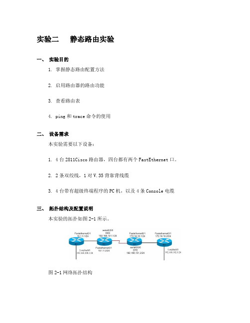
2. 2条双绞线,1对V.35背靠背线缆3. 4台带有超级终端程序的PC机,以及4条Console电缆三、拓扑结构及配置说明本实验的拓扑如图2-1所示。
图2-1网络拓扑结构4台路由器分别命名为R1、R2、R3和R4。
所使用的ip地址分配如图1-1所示。
图中的“/24”表示子网掩码为24位,即255.255.255.0。
实验中,应使用静态路由的设置,实现R1到R4在IP层的连通性,即要求从R1可以ping通R4,反之亦然。
四、实验步骤1. 恢复路由器的初始配置。
(若路由器末被配置过则直接做第三步)2. 给路由器命名router>enable //进入特权模式Router #config terminal //进入配置模式Enter configuration commands, one per line. End with CNTL/Z.Router (config) #Router (config)#hostname r1 //给路由器命名R1 (config)#其它路由器配置类似3. 配置端口IPR1 (config)# interface FastEthernet0/1 //进入FastEthernet0/1端口r1(config-if)#ip address 10.1.1.1 255.255.255.0 //指定端口的IP地址及子网掩码r1(config-if)#no shut //开启端口r1(config-if)#exit //退出端口模式R1 (config)#interface Loopback0 //进入本地回环接口0r1(config-if)#ip address 192.168.100.1 255.255.255.0其它路由器配置类似配完各个路由器的名字及IP后,通过sh run(特权模式下的命令)命令查看路由器的配置把你所看到的结果记录下来。
实验四.配置静态路由和缺省路由
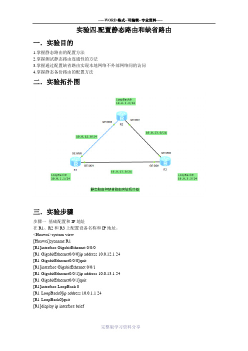
实验四.配置静态路由和缺省路由一.实验目的1.掌握静态路由的配置方法2.掌握测试静态路由连通性的方法3.掌握通过配置缺省路由实现本地网络不外部网络间的访问4.掌握静态备份路由的配置方法二.实验拓扑图三.实验步骤步骤一基础配置和IP地址在R1、R2和R3上配置设备名称和IP地址。
<Huawei>system-view[Huawei]sysname R1[R1]interface GigabitEthernet 0/0/0[R1-GigabitEthernet0/0/0]ip address 10.0.12.1 24[R1-GigabitEthernet0/0/0]quit[R1]interface GigabitEthernet 0/0/1[R1-GigabitEthernet0/0/1]ip address 10.0.13.1 24[R1-GigabitEthernet0/0/1]quit[R1]interface LoopBack 0[R1-LoopBack0]ip address 10.0.1.1 24[R1-LoopBack0]quit[R1]display ip interface brief<Huawei>system-view[Huawei]sysname R2[R2]interface GigabitEthernet 0/0/0[R2-GigabitEthernet0/0/0]ip address 10.0.12.2 24 [R2-GigabitEthernet0/0/0]quit[R2]interface GigabitEthernet 0/0/1[R2-GigabitEthernet0/0/1]ip address 10.0.23.1 24 [R2-GigabitEthernet0/0/1]quit[R2]interface LoopBack 0[R2-LoopBack0]ip address 10.0.2.2 24[R2-LoopBack0]quit[R2]display ip interface brief<Huawei>system-view[Huawei]sysname R3[R3]interface GigabitEthernet 0/0/0[R3-GigabitEthernet0/0/0]ip address 10.0.23.2 24 [R3-GigabitEthernet0/0/0]quit[R3]interface GigabitEthernet 0/0/1[R3-GigabitEthernet0/0/1]ip address 10.0.13.2 24 [R3-GigabitEthernet0/0/1]quit[R3]interface LoopBack 0[R3-LoopBack0]ip address 10.0.3.3 24[R3-LoopBack0]quit[R3]display ip interface brief执行ping命令,检测R1与其它设备间的连通性。
静态路由协议配置方法
⼀、两个路由器的配置⽅法 1、R1的S0⼝地址是:192.168.1.1;E0⼝地址是:10.10.10.254。
R2的S0⼝地址是:192.168.1.2;E0⼝地址是:20.20.20.254。
2、R1的S0端⼝增加IP地址:在全局配置模式下进⼊S0端⼝,命令:interface s 0;然后添加IP地址:ip address192.168.1.1 255.255.255.0,激活端⼝:no shutdown;其它端⼝⽤相同的⽅法添加。
3、假定上例中R1的端⼝是DCE端,R2为DTE端,那么就要在R1的S0端⼝中配置时钟频率和绑定带宽,时钟频率:clock rate 72000;绑定带宽:bandwidth 72;⽽在R2的S0端⼝中绑定带宽:bandwidth 72。
4、配置静态路由协议要在全局配置模式下配置。
A)在R1上配置从R1到R2的路由协议,命令格式:ip route ⽬标地址段⽬标地址⼦掩码下⼀跳地址(即距离此路由器最近相连的S0地址);命令:ip route 20.20.20.0 255.255.255.0 192.168.1.2。
R1的路由协议即配置完毕。
B)R2配置与R1相同,只不过是反过来就可以了。
ip route 10.10.10.0 255.255.255.0 192.168.1.1。
⼆、三个路由器的配置⽅法1、路由器R1、R2、R3,R1的S0接R2的S0,R2的S1接R3的S0,R1与R2之间R1为DCE,R2与R3之间R2为DCE。
R1的S0地址:192.168.1.1,E0地址:10.10.10.254。
R2的S0地址:192.168.1.2,E0地址:20.20.20.254,S1地址:172.16.1.1。
R3的S0地址:172.16.1.2,E0地址:30.30.30.254。
2、IP地址的增加及时钟频率的增加、带宽的绑定,参见上⾯的⽅法。
路由器及其配置(三)_真题-无答案

路由器及其配置(三)(总分93,考试时间90分钟)1. 在cisco路由器上用write memory命令可以将路由器的配置保存到______。
A. TFTP ServerB. Flash MemoryC. NVRAMD. RAM2. 请根据下图所示网络结构回答下列问题。
(1) 填写路由器RG的路由表项①至⑤目的网络/掩码长度输出端口① SO(直接连接)② S1(直接连接)③ SO④ S1⑤ SO⑥ S1(2) 如果需要监听路由器RF和RG之间的所有流量,可以在该链路中串入一种设备,请写出这种设备的名称(3) 若要检测从windows主机192.168.64.215到主机192.168.66.195数据包的传输路径,请写出应使用的命令名称,并依次写出数据包经过的路由器名称。
(4) 如果将192.168.66.128/25划分为三个子网,其中子网1能容纳50台主机,子网2和子网3分别能容纳20台主机,要求网络地址从小到大依次分配给三个子网,请写出前两个子网的掩码和可用的IP地址段。
3. 主要用于存储启动配置(starting config) 文件或备份配置文件的路由器内存是______。
A. ROMB. RAMC. NVRAMD. SDROM4. Cisco路由器执行show access-list的命令显示如下一组信息Standard IP access list blockdeny 10.0.0.0,wildcard bits 0.255.255.255 logdeny 172.16.0.0,wildcard bits 0.15.255.255permit any根据上述信息,正确的access-list配置是______。
A. Router(config) #access-list standard blockRouter(config-std-nacl) #deny 10.0.0.0 255.0.0.0 logRouter(config-std-nacl) #deny 172.16.0.0 255.240.0.0Router(config-std-nacl) #permit anyB. Router(config) #ip accesa-list standard blockRouter(config-std-nacl) #permit anyRouter(config-std-nacl) #deny 10.0.0.0 0.255.255.255 logRouter(config-std-nacl) #deny 172.16.0.0 0.15.255.255C. Router(config) #ip access-list standard blockRouter(config-std-nacl) #deny 10.0.0.0 255.0.0.0 logRouter(config-std-nacl) #deny 172.16.0.0 255.240.0.0Router(config-std-nacl) #permit anyD. Router(config) #access-list standard blockRouter(config-std-nacl) #deny 10.0.0.0 0.255.255.255 logRouter(config-std-nacl) #deny 172.16.0.0 0.15.255.255Router(config-std-nacl) #permit any5. 请根据下图所示网络结构回答下列问题。
13路由器基本开局配置、静态路由配置SHZB (1)

规格型号
路由器
NE20E-S2E
尾纤
LC-LC
LC插座固定光衰
光纤清洁器
光功率计
单位 台 根 个 个 台
数量 3 4 2 1 1
备注 5db
04 实训内容
电力系统通信运维综合实训
1.开局配置R1、R2、R3三台路由器,如下图所示,要求正 确命名设备名称 2.正确配置并划分R1、R2、R3路由器接口上IP地址。 3.配置要求: R1的G0/0/0和R3的G0/0/1的IP地址可以相互ping 通,要求带上源地址ping测试。(使用静态路由,不允许使 用动态路由协议) 4.测试命令及结果截图保存
电力系统通信运维综合实训
路由器基本开局配置、静态路由 配置
1
C目 录 ONTENTS
2 3
4
实训目标 实训知识要点 工器具与耗材 实训内容
C目 录 ONTENTS
5 风险分析及安全控制措施 6 组织和质量、安全管控 7 指导书执行情况评估
01
实训目标
• 路由介绍 • 理解静态路由 • 静态路由配置
电力系统通信运维综合实训
• destination:目的地址,用来标识IP包的目的地址或目的网络。 • mask:网络掩码,与目的地址一起标识目的主机或者路由器所在网段的地
址。 • pre:标识路由加入IP路由表的优先级。可能到达一个目的地的有多条路由,
但是优先级的存在让他们先选择优先级高的路由进行利用。 • cost:路由开销,当到达一个目的地的多个路由优先级相同时,路由开销
将通过“最长匹配原则”,选出加入路由表的路由,如图4。
查找路由表
目的地址与掩码分 别做“与”操作
匹配
与路由表中的目的 地址做比较
静态路由配置的实训操作步骤
静态路由配置的实训操作步骤以静态路由配置的实训操作步骤为标题,写一篇文章一、实训背景介绍在网络通信中,静态路由是一种简单而有效的路由配置方式。
它通过手动配置路由表的方式,指定了数据包从源网络到目标网络的路径。
本实训将介绍如何进行静态路由的配置,以实现网络设备之间的通信。
二、实训准备工作1. 确定网络拓扑结构:确定需要进行静态路由配置的网络设备,并绘制出网络拓扑图,包括各设备的连接关系和IP地址分配情况。
2. 确定路由器的管理IP地址:为每个路由器设备分配一个唯一的管理IP地址,用于远程登录和配置路由器。
3. 确定网络设备的接口IP地址:为每个网络设备的接口分配一个唯一的IP地址,用于实现设备之间的通信。
三、静态路由配置步骤1. 登录路由器:使用Telnet或SSH等远程登录工具,通过管理IP 地址登录到需要配置静态路由的路由器。
2. 进入全局配置模式:在路由器的命令行界面中输入"enable"命令,进入特权模式,然后输入"configure terminal"命令,进入全局配置模式。
3. 配置静态路由:在全局配置模式下,输入"ip route 目标网络目标网络掩码下一跳地址"命令,配置静态路由。
其中,目标网络为需要访问的目标网络地址,目标网络掩码为目标网络的子网掩码,下一跳地址为数据包的下一跳路由器的IP地址。
4. 保存配置:输入"end"命令退出配置模式,然后输入"write"命令保存配置。
四、实训操作示例假设有两台路由器R1和R2,它们之间通过以太网连接。
R1的管理IP地址为192.168.1.1,R2的管理IP地址为192.168.2.1。
R1的接口IP地址为192.168.1.254,R2的接口IP地址为192.168.2.254。
现在需要配置R1和R2之间的静态路由。
1. 登录R1路由器:使用Telnet工具,输入192.168.1.1,登录到R1路由器。
实验 2.8.2:静态路由配置练习
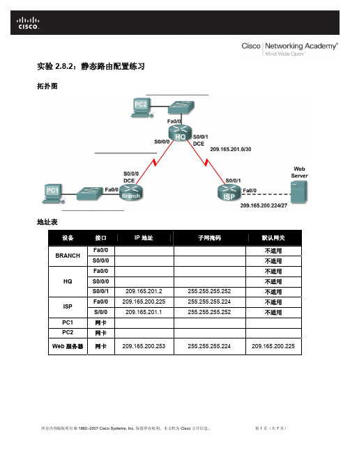
实验 2.8.2:静态路由配置练习拓扑图地址表设备接口IP 地址子网掩码默认网关Fa0/0 不适用BRANCHS0/0/0 不适用Fa0/0 不适用HQS0/0/0 不适用S0/0/1 209.165.201.2 255.255.255.252 不适用Fa0/0 209.165.200.225 255.255.255.224 不适用ISPS/0/0 209.165.201.1 255.255.255.252 不适用PC1 网卡PC2 网卡Web 服务器网卡209.165.200.253 255.255.255.224 209.165.200.225学习目标完成本实验后,您将能够:•根据指定的要求对地址空间划分子网。
•为接口分配适当的地址,并进行记录。
•根据拓扑图进行网络布线。
•清除启动配置并将路由器重新加载为默认状态。
•在路由器上执行基本配置任务。
•配置并激活串行接口和以太网接口。
•确定适当的静态路由、总结路由和默认路由。
•测试并校验配置。
•思考网络实施并整理成文档。
场景在本次实验练习中,您将得到一个网络地址,您必须对其进行子网划分以便完成如拓扑结构图所示的网络编址。
连接到 ISP 路由器的 LAN 编址和 HQ 与 ISP 路由器之间的链路已经完成。
但还需要配置静态路由以便非直连网络中的主机能够彼此通信。
任务 1:对地址空间划分子网。
步骤 1:研究网络要求。
连接到 ISP 路由器的 LAN 编址和 HQ 与 ISP 路由器之间的链路已经完成。
在您的网络设计中,您可以使用 192.168.2.0/24 地址空间。
请对该网络进行子网划分,以提供足够的 IP 地址来支持 60 台主机。
步骤 2:创建网络设计时请思考以下问题:需要将 192.168.2.0/24 网络划分为多少个子网? __________这些子网的网络地址分别是什么?子网 0: ________________________________________子网 1: ________________________________________子网 2: ________________________________________子网 3: ________________________________________这些网络以点分十进制格式表示的子网掩码是什么? __________________________以斜杠格式表示的网络子网掩码是什么? __________每个子网可支持多少台主机? __________步骤 3:为拓扑图分配子网地址。
静态路由实验1(静态路由的基本配置)

设备接⼝ IP 地址PC-1Ethnet0/0/1192.168.10.10静态路由实验1(静态路由的基本配置)概述:静态路由是指⽤户或⽹络管理员⼿⼯配置的路由信息。
当⽹络的拓扑结构或链路状 态发⽣改变时,需要⽹络管理⼈员⼿⼯修改静态路由信息。
相⽐于动态路由协议,静态 路由⽆需频繁地交换各⾃的路由表,配置简单,⽐较适合⼩型.简单的⽹络环境。
静态路由不适合⼤型和复杂的⽹络环境,因为当⽹络拓扑结构和链路状态发⽣变化 时,⽹络管理员需要做⼤量的调整,且⽆法⾃动感知错误发⽣,不易排错。
默认路由是⼀种特殊的静态路由,当路由表中与数据包冃的地址没有匹配的表项时, 数据包将根据默认路由条⽬进⾏转发。
默认路由在某些时候⾮常有效,如在末梢⽹络中, 默认路由可以⼤⼤简化路由器配置,减轻⽹络管理员的⼯作负担。
实验内容:在由3 台路由器所组成的简单⽹络中,R1与R3各⾃连接着⼀台主机,现在要求能够实 现主机PC-1与PC-2之间的正常通信。
本实验将通过配置基本的静态路由和默认路由来实现。
实验拓扑:实验编址:Ethnet0/0/1192.168.10.1 R1(Router)10.0.12.1Serial0/0/0Serial0/0/110.0.12.2R2(Router)Serial0/0/010.0.23.2Serial0/0/110.0.23.3R3(Router)Ethnet0/0/1192.168.20.3Ethnet0/0/1192.168.20.20 PC-2实验步骤:1 .基本配置根据实验编址表进⾏相应的基本配置,并使⽤ping命令检测各直连链路的连通性。
其余直连⽹段的连通性测试省略。
各直连链路间的IP连通性测试完成后,现尝试在主机PC-1上直接ping主机PC-2。
发现⽆法连通,这时需要思考是什么问题导致了它们之间⽆法通信,我们⼀步步测试⾸先查看主机PC-1与其⽹关设备R1间能否正常通信。
主机与⽹关之间通信正常,接下来检查⽹关设备R1上的路由表。
静态路由实验实训总结报告

一、实验目的本次静态路由实验实训的主要目的是通过实际操作,加深对静态路由原理的理解,掌握静态路由的配置方法,以及了解静态路由在实际网络中的应用。
通过实验,提高网络设备的配置和管理能力,为今后从事网络工作打下基础。
二、实验内容1. 实验环境:使用三台路由器(R1、R2、R3)和一台交换机,搭建一个简单的网络拓扑结构。
2. 实验步骤:(1)配置路由器接口IP地址:为R1、R2、R3配置相应的接口IP地址,并设置子网掩码。
(2)配置静态路由:在R1上配置到达R2的静态路由,在R2上配置到达R3的静态路由,在R3上配置到达R1的静态路由。
(3)测试网络连通性:使用ping命令测试不同路由器之间的连通性。
(4)修改静态路由:修改R1上的静态路由,测试网络连通性是否受到影响。
(5)删除静态路由:删除R2上的静态路由,测试网络连通性是否受到影响。
三、实验过程及结果1. 配置路由器接口IP地址:按照实验要求,为三台路由器的接口配置了相应的IP地址和子网掩码。
2. 配置静态路由:在R1上配置到达R2的静态路由,命令如下:R1> ip route 192.168.2.0 255.255.255.0 192.168.1.2在R2上配置到达R3的静态路由,命令如下:R2> ip route 192.168.3.0 255.255.255.0 192.168.2.2在R3上配置到达R1的静态路由,命令如下:R3> ip route 192.168.1.0 255.255.255.0 192.168.3.23. 测试网络连通性:使用ping命令测试不同路由器之间的连通性,结果如下:R1> ping 192.168.2.2Pinging 192.168.2.2 with 32 bytes of data:Reply from 192.168.2.2: bytes=32 time=1ms TTL=255...R2> ping 192.168.1.2Pinging 192.168.1.2 with 32 bytes of data:Reply from 192.168.1.2: bytes=32 time=1ms TTL=255...R3> ping 192.168.3.2Pinging 192.168.3.2 with 32 bytes of data:Reply from 192.168.3.2: bytes=32 time=1ms TTL=255...4. 修改静态路由:将R1上的静态路由修改为到达R2的下一跳地址为192.168.1.1,命令如下:R1> ip route 192.168.2.0 255.255.255.0 192.168.1.1测试网络连通性,发现连通性受到影响。
实验1. 配置静态路由

实验1. 静态路由基础配置1 应用背景管理员可以通过手工的方法在路由器中直接配置路由表,这就是静态路由。
虽然静态路由不适合于在大的网络中使用,但是由于静态路由简单、路由器负载小、安全性高等原因,现在在ISP、金融、证券等单位经常被使用。
2 实验目的通过本实验,掌握以下技能:◆路由表的概念◆命令ip route的使用,以及静态路由跟下一条地址和接口◆根据需求正确的配置静态路由◆掌握验证静态路由的命令3 设备需求:思科路由器 3640 三台4 实验拓扑:Hlsz_R1Hlsz_R3Hlsz_R2LOOPBACK 0Ip add 1.1.1.1/32LOOPBACK 0Ip add 3.3.3.3/32成都互联神州网络技术培训S2/0S2/0S2/1S2/15 实验步骤5.1、静态路由配置静态路由让R1 loopback 0:1.1.1.1/24、R2 loopback 0:2.2.2.2/24、R3 loopback 0:3.3.3.3/24能够相互通信5.1.1、基本配置配置接口IP地址,保证直连链路的互通R1(config)#int loopback0R1(config-if)#ip address 1.1.1.1 255.255.255.0R1(config)#int s2/0R1(config-if)#ip address 12.1.1.1 255.255.255.0R1(config-if)#no shutdownR2(config)#int loopback0R2(config-if)#ip address 2.2.2.2 255.255.255.0R2(config)#int s2/0R2(config-if)#clock rate 64000 /DCE端配置时钟速率R2(config-if)#ip address 12.1.1.2 255.255.255.0R2(config-if)#no shutdownR2(config)#int s2/1R2(config-if)#clock rate 64000 /DCE端配置时钟速率R2(config-if)#ip address 23.1.1.2 255.255.255.0R2(config-if)#no shutdownR3(config)#int loopback0R3(config-if)#ip address 3.3.3.3 255.255.255.0R3(config)#int s2/1R3(config-if)#ip address 23.1.1.3 255.255.255.0R3(config-if)#no shutdown5.1.2、配置静态路由静态路由指向下一跳地址R1(config)#ip route 3.3.3.0 255.255.255.0 12.1.1.2R1(config)#ip route 2.2.2.0 255.255.255.0 12.1.1.2R1(config)#ip route 23.1.1.0 255.255.255.0 12.1.1.2/在R1上配置静态路由分别到网段:23.1.1.0、3.3.3.0和2.2.2.0,采用下一跳IP地址的形式,注意IP:12.1.1.2是R2上S2/0接口IP地址。
习题1111

静态路由一、实验设备三台28系列型号路由器通过串口相连。
二、实验要求三台路由连接5个网段,配置静态路由和缺省路由。
R2为DCE端。
RIPV1一、实验设备两台28系列型号路由器通过串口相连。
二、实验要求2台路由器分别命名为Router1和Router2,路由器之间通过串口连接,采用V.35 DCE/DTE电缆。
将电缆的DCE端连接到Router1的串口Serial 0上,PC1的IP地址和缺省网关分别为172.16.1.2和172.16.1.1,PC2的IP地址和缺省网关分别为172.16.3.2和172.16.3.1,网络掩码都是255.255.255.0 。
RIPV2一、实验设备两台28系列型号路由器通过串口相连。
二、实验要求根据拓扑结果图,用RIPv2协议配置使全网互通。
静态路由答案三、实验步骤Router>enRouter#conf tRouter(config)# hostname R1R1(config)#intfa0/1 进入fa0/1端口R1(config-if)#ip address 192.168.0.1 255.255.255.0添加fa0/1口的IPR1(config-if)#no shutdown 打开fa0/1端口R1(config-if)#exitR1(config)#int s1/0R1(config-if)# ip address 192.168.1.1 255.255.255.0R1(config-if)# no shutdownR1(config-if)#exitR1(config)#ip route 0.0.0.0 0.0.0.0 192.168.1.2 添加缺省路由Router>enRouter#conf tRouter(config)# hostname R2R2 (config)#intfa0/1R2 (config-if)#ip address 192.168.4.1 255.255.255.0R2 (config-if)#no shutdownR2 (config-if)#exitR2 (config)#int s1/0 NR2 (config-if)#ip address 192.168.1.2 255.255.255.0R2 (config-if)#clock rate 56000设置时钟R2 (config-if)#no shutdownR2 (config-if)#exitR2 (config)#int s1/1R2 (config-if)#ip address 192.168.2.1 255.255.255.0R2 (config-if)#clock rate 56000R2 (config-if)#no shutR2 (config-if)#exitR2 (config)#ip route 192.168.0.0 255.255.255.0 192.168.1.1 添加静态路由R2 (config)#ip route 192.168.3.0 255.255.255.0 192.168.2.2 添加静态路由Router>enRouter#conf tRouter(config)# hostname R3R3(config)#intfa0/1R3 (config-if)#ip address192.168.3.1255.255.255.0R3 (config-if)#no shutdownR3 (config-if)#exitR3 (config)#int s1/0R3 (config-if)#ip address 192.168.2.2 255.255.255.0R3 (config-if)#no shutR3 (config-if)#exitR3 (config)#ip route 0.0.0.0 0.0.0.0 192.168.3.1 添加缺省路由在R2上操作:R2 #show cdp neighbors 查看邻居汇总信息R2 #show cdp neighbors detail 查看所有邻居的详细信息R2 #show cdp显示CDP信息R2 #show cdp traffic 显示CDP所用的数据包的信息R2 #show cdp entry * 显示所有相邻路由器的所有信息R2 #un all 关闭所有DEBUG信息R2 #(config)#cdp run 启动CDP协议R2 #show cdp interface (端口) 显示该端口的CDP信息R2 #clear cdp counter 清除CDP计数器R2 #debug cdp packet 启动CDP数据包调试模式【注意事项】1.DCE应该在路由器2的的两个接口上都配置时钟频率。
TCPIP实验
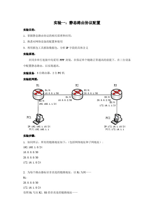
实验一:静态路由协议配置实验目的:1.掌握静态路由协议的相关原理和应用; 2.熟悉对网络设备的配置和使用3.利用抓包工具抓取数据包,分析IP 字段的具体含义 实验原理:在同步串行连接中均采用PPP 封装,在保证单个链路正常通讯的前提下,在三台设备中配置静态路由,以实现通讯。
实验设备:3台路由器,2台PC 机 实验组网图:R3R2R1PC1网关:192.168.1.1网关:172.16.1.1实验步骤:1. 如同所示,所有的链路地址如下:(包括网络地址和子网地址): 192.168.1.0/24 10.0.0.0/30 20.0.0.0/30 172.16.1.0/242. 为每个路由器标识非直连的链路地址,以R1为例—— R1: 20.0.0.0/30 172.16.1.0/24仿照R1写出R2、R3的非直连的链路地址——R2:192.168.1.0/24172.16.1.0/24R3:192.168.1.0/2410.0.0.0/303. 为每个路由器写出非直连的地址的路由语句,以R1为例——R1:ip route-static 20.0.0.0 30 10.0.0.2ip route-static 172.16.1.0 24 10.0.0.2仿造R1写出R2、R3的非直连的地址的路由语句——R2:ip route-static 192.168.1.0 24 10.0.0.1ip route-static 172.16.1.0 24 20.0.0.2R3:ip route-static 192.168.1.0 24 20.0.0.1ip route-static 10.0.0.0 30 20.0.0.14. 选择设备,按照实验组网图进行物理连接。
注意各接口的正确连接。
5.确保物理连接正确后,通过管理控制系统登陆要配置的路由器,在每个路由器上配置静态路由,具体配置如下:R1:<H3C>system-view[H3C]sysname R1[R1]interface s1/0[R1-Serial1/0]ip addr 10.0.0.1 30[R1-Serial1/0]int e8/0[R1-Ethernet8/0]ip addr 192.168.1.1 24[R1-Ethernet8/0]quit[R1]ip route-static 20.0.0.0 30 10.0.0.2[R1]ip route-static 172.16.1.0 24 10.0.0.2R2:<H3C>system-view[H3C]sysname R2[R2]interface s1/0[R2-Serial1/0]ip addr 10.0.0.2 30[R2-Serial1/0]interface s2/0[R2-Serial2/0]ip addr 20.0.0.1 30[R2-Serial2/0]quit[R2]ip route-static 192.168.1.0 24 10.0.0.1[R2]ip route-static 172.16.1.0 24 20.0.0.2R3:<H3C>system-view[H3C]sysname R3[R3]interface s2/0[R3-Serial2/0]ip addr 20.0.0.2 30[R3-Serial2/0]int e8/0[R3-Ethernet8/0]ip addr 172.16.1.1 24[R3-Ethernet8/0]quit[R3]ip route-static 10.0.0.0 30 20.0.0.1[R3]ip route-static 192.168.1.0 24 20.0.0.16.分析验证:(1)按图示为pc1和pc2配置ip地址和网关,然后pc1 ping 路由器各端口地址和pc2是否为通? ping之前打开pc上的抓包工具,ping后从抓取到的数据中选取一条ICMP request 包,分析其中的IP层字段。
实验六 静态路由与缺省路由配置

静态路由与缺省路由配置1.实验目标在本试验,我们将学习如何用静态路由和缺省路由两种方法配置路由器2.实验拓扑图1是本实验用到的拓扑。
图1 静态路由及缺省路由配置图示3.实验要求某公司在深圳、上海、北京各有一分公司,为了使得各分公司的网络能够通信,公司在三地分别购买了路由器,为R1、R2、R3,同时申请了DDN线路。
现要用静态路由配置各路由器使得三地的网络能够通信。
4.实验步骤⑴ R1路由器配置IP地址和IP路由:R1#conf tR1(config)#interface f0/0R1(config-if)#ip address 10.1.1.254 255.255.255.0R1(config-if)#no shutdownR1(config-if)#interface s0/0R1(config-if)#ip address 10.1.2.1 255.255.255.0R1(config-if)#no shutdownR1(config-if)#exitR1(config)#ip route 10.1.4.0 255.255.255.0 10.1.2.2⑵ R2路由器配置IP地址和IP路由:R2#conf tR2(config)#interface s0/0R2(config-if)#ip address 10.1.2.2 255.255.255.0 R2(config-if)#clock rate 64000R2(config-if)#no shutdownR2(config-if)#i nterface s0/1R2(config-if)#ip address 10.1.3.1 255.255.255.0R2(config-if)#clock rate 64000R2(config-if)#no shutdownR2(config-if)#exitR2(config)#ip route 10.1.1.0 255.255.255.0 10.1.2.1R2(config)#ip route 10.1.4.0 255.255.255.0 10.1.3.2⑶ R3路由器配置IP地址和IP路由:R3#conf tR3(config)#interface f0/0R3(config-if)#ip address 10.1.4.254 255.255.255.0 R3(config-if)#no shutdownR3(config-if)#interface s0/0R3(config-if)#ip address 10.1.3.2 255.255.255.0R3(config-if)#no shutdownR3(config-if)#exitR3(config)#ip route 10.1.2.0 255.255.255.0 10.1.3.1⑷在R1、R2、R3路由器上检查接口、路由情况:R1#show ip routeR1#s how ip interfacesR1#show interfaceR2#show ip routeR2#show ip interfacesR2#show interfaceR3#show ip routeR3#show ip interfacesR3#show interface【问题1】:路由器上的路由器表各有几条,分别是什么类型?⑸在各路由器上用“ping”命令测试到各网络的连通性⑹在R1、R3上取消已配置的静态路由,R2保持不变:R1:R1(config)#no ip route 10.1.3.0 255.255.255.0 10.1.2.2 R1(config)#no ip route 10.1.4.0 255.255.255.0 10.1.2.2 R1(config)#exitR1#show ip routeR3:R3(config)#no ip route 10.1.1.0 255.255.255.0 10.1.3.1 R3(config)#no ip route 10.1.2.0 255.255.255.0 10.1.3.1 R3(config)#exitR3#show ip route⑺在R1、R3上配置缺省路由:R1:R1(config)#ip route 0.0.0.0 0.0.0.0 10.1.2.2R1(config)#ip classlessR3:R3(config)#ip route 0.0.0.0 0.0.0.0 10.1.3.1R3(config)#ip classless【问题2】为什么要配置“ip classless”?⑻在各路由器上用“ping”命令测试到各网络的连通性【问题3】缺省路由用在什么场合较好?5.实验问题参考答案【问题1】:都分别有4条路由,即到4个网络的路由,各自有两条直连网络的路由(用‘c’表示)和两条静态路由(用‘s’表示)。
第四章路由器基础练习题

第四章路由器基础练习题《⽹络互联技术》练习题第四章:路由器基础⼀、填空题1、路由器的两⼤主要功能是:_______和数据交换。
2、路径选择发⽣在OSI体系的________。
3、能够将数据包从⼀个⼦⽹上的主机转发到另⼀个⼦⽹上的上机的⽹络层协议称为___________。
4、路由协议的最终⽬的是⽣成__________。
5、路由器的存储器包括:BootRom、Ram/Dram、Nvram和________。
6、路由器的启动配置⽂件存储在_____________。
7、路由表形成的三种途径是:________、静态路由和动态路由。
8、ip classless命令的作⽤是_________________。
⼆、单项选择题1、校园⽹架设中,作为本校园与外界的连接器应采⽤( )。
A、中继器B、⽹桥C、⽹关D、路由器2、下列哪个设备是⽹络与⽹络连接的桥梁,是因特⽹中最重要的设备( )。
A、中继器B、集线器C、路由器D、服务器3、对不同规模的⽹络,路由器所起的作⽤的侧重点不同。
在主⼲⽹上,路由器的主要作⽤是( )。
A、路由选择B、差错处理C、分隔⼦⽹D、⽹络连接4、在⽹络层提供协议转换,在不同⽹络之间存贮转发分组的⽹络设备是( )。
A、⽹桥B、⽹关C、集线器D、路由器5、在园区⽹内部,路由器的主要作⽤是( )。
A、路由选择D、⽹络连接6、路由器技术的核⼼内容是( )。
A、路由算法和协议B、提⾼路由器性能⽅法C、⽹络地址复⽤⽅法D、⽹络安全技术7、路由器性能的主要决定因素是( )。
A、路由算法的效率B、路由协议的效率C、路由地址复⽤的程度D、⽹络安全技术的提⾼8、关于路由器,下列说法中错误的是()。
A、路由器可以隔离⼦⽹,抑制⼴播风暴B、路由器可以实现⽹络地址转换C、路由器可以提供可靠性不同的多条路由选择D、路由器只能实现点对点的传输9、路由器最主要的功能是路径选择和进⾏()A、封装和解封装数据包B、丢弃数据包C、转发数据包D、过滤数据包10、下列属于路由表的产⽣⽅式的是()。
网络练习题参考答案

第1章计算机网络的基本概念一.填空(1)按照覆盖的地理范围,计算机网络可以分为______、______和______。
【答案】:局域网、城域网、广域网(2)ISO/OSI参考模型将网络分为______层、______层、______层、______层、______层、______层和______层。
【答案】:物理、数据链路、网络、传输、会话、表示、应用(3)建立计算机网络的主要目的是:________。
【答案】:资源共享和在线通信二.单项选择(1)在TCP/IP体系结构中,与OSI参考模型的网络层对应的是:a)主机—网络层 b)互联层c)传输层d)应用层【答案】:b(2)在OSI参考模型中,保证端-端的可靠性是在哪个层次上完成的a)数据链路层b)网络层c)传输层d)会话层【答案】:c三.问答题计算机网络为什么采用层次化的体系结构【要点提示】采用层次化体系结构的目的是将计算机网络这个庞大的、复杂的问题划分成若干较小的、简单的问题。
通过“分而治之”,解决这些较小的、简单的问题,从而解决计算机网络这个大问题(可以举例加以说明)。
第2章局域网的基本知识一.填空(1)最基本的网络拓扑结构有三种,他们是________、________和________。
【答案】:总线型、环形、星形(2)以太网使用________介质访问控制方法,而FDDI则使用________介质访问控制方法。
【答案】:CSMA/CD、令牌环二.单项选择(1)MAC地址通常存储在计算机的a)内存中b)网卡上c)硬盘上d)高速缓冲区【答案】:b(2)在以太网中,冲突a)是由于介质访问控制方法的错误使用造成的b)是由于网络管理员的失误造成的c)是一种正常现象d)是一种不正常现象【答案】:c(3)下面关于以太网的描述哪个是正确的a)数据是以广播方式发送的b)所有节点可以同时发送和接收数据c)两个节点相互通信时,第三个节点不检测总线上的信号d)网络中有一个控制中心,用于控制所有节点的发送和接收【答案】:a三.问答题请简述以太网和FDDI网的工作原理和数据传输过程。
华为静态路由实验练习
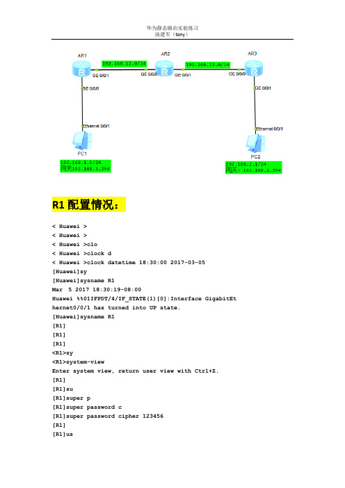
R1配置情况:<Huawei><Huawei><Huawei>clo<Huawei>clock d<Huawei>clock datetime 18:30:00 2017-03-05[Huawei]sy[Huawei]sysname R1Mar 5 2017 18:30:19-08:00 Huawei %%01IFPDT/4/IF_STATE(l)[0]:Interface GigabitEthernet0/0/1 has turned into UP state.[Huawei]sysname R1[R1][R1][R1]<R1>sy<R1>system-viewEnter system view, return user view with Ctrl+Z.[R1][R1]su[R1]super p[R1]super password c[R1]super password cipher 123456[R1][R1]us[R1]user-i[R1]user-interface v[R1]user-interface vty 0 4[R1-ui-vty0-4][R1-ui-vty0-4]au[R1-ui-vty0-4]authentication-mode p[R1-ui-vty0-4]authentication-mode passwordPlease configure the login password (maximum length 16):123456[R1-ui-vty0-4][R1-ui-vty0-4]se[R1-ui-vty0-4]set au[R1-ui-vty0-4]set authentication p[R1-ui-vty0-4]set authentication password c[R1-ui-vty0-4]set authentication password cipher 123456[R1-ui-vty0-4][R1-ui-vty0-4]q[R1][R1][R1]int[R1]interface g[R1]interfaceGigabitEthernet 0/0/0[R1-GigabitEthernet0/0/0][R1-GigabitEthernet0/0/0]ip add[R1-GigabitEthernet0/0/0]ip address 192.168.1.254 24[R1-GigabitEthernet0/0/0]Mar 5 2017 18:51:37-08:00 R1 %%01IFNET/4/LINK_STATE(l)[0]:The line protocol IPon the interface GigabitEthernet0/0/0 has entered the UP state. [R1-GigabitEthernet0/0/0][R1-GigabitEthernet0/0/0]un[R1-GigabitEthernet0/0/0]undosh[R1-GigabitEthernet0/0/0]undo shutdownInfo: Interface GigabitEthernet0/0/0 is not shutdown.[R1-GigabitEthernet0/0/0]q[R1][R1]int[R1]interface g[R1]interfaceGigabitEthernet 0/0/1[R1-GigabitEthernet0/0/1]ip ad[R1-GigabitEthernet0/0/1]ip address 192.168.12.1 24[R1-GigabitEthernet0/0/1]Mar 5 2017 18:53:23-08:00 R1 %%01IFNET/4/LINK_STATE(l)[1]:The line protocol IPon the interface GigabitEthernet0/0/1 has entered the UP state.[R1-GigabitEthernet0/0/1]un[R1-GigabitEthernet0/0/1]undosh[R1-GigabitEthernet0/0/1]undo shutdownInfo: Interface GigabitEthernet0/0/1 is not shutdown.[R1-GigabitEthernet0/0/1][R1-GigabitEthernet0/0/1]q[R1][R1]dis[R1]displayipint[R1]displayip interface b[R1]displayip interface brief*down: administratively down^down: standby(l): loopback(s): spoofingThe number of interface that is UP in Physical is 3The number of interface that is DOWN in Physical is 1The number of interface that is UP in Protocol is 3The number of interface that is DOWN in Protocol is 1Interface IP Address/Mask Physical Protocol GigabitEthernet0/0/0 192.168.1.254/24 up up GigabitEthernet0/0/1 192.168.12.1/24 up up GigabitEthernet0/0/2 unassigned down downNULL0 unassigned up up(s) [R1][R1][R1]Please check whether system data has been changed, and save data in time Configuration console time out, please press any key to log on<R1><R1><R1><R1>syEnter system view, return user view with Ctrl+Z.[R1][R1][R1]ipro[R1]ip route-[R1]ip route-static 192.168.23.0 255.255.255.0 192.168.12.2[R1][R1]ipro[R1]ip route-[R1]ip route-static 192.168.2.0 255.255.255.0 192.168.23.2[R1][R1][R1]dis[R1]displayipro[R1]displayip routing-tableRoute Flags: R - relay, D - download to fib------------------------------------------------------------------------------Routing Tables: PublicDestinations : 12 Routes : 12Destination/Mask Proto Pre Cost Flags NextHopInterface127.0.0.0/8 Direct 0 0 D 127.0.0.1 InLoopBack0127.0.0.1/32 Direct 0 0 D 127.0.0.1 InLoopBack0127.255.255.255/32 Direct 0 0 D 127.0.0.1 InLoopBack0192.168.1.0/24 Direct 0 0 D 192.168.1.254 GigabitEthernet0/0/0192.168.1.254/32 Direct 0 0 D 127.0.0.1 GigabitEthernet0/0/0192.168.1.255/32 Direct 0 0 D 127.0.0.1 GigabitEthernet0/0/0192.168.2.0/24 Static 60 0 RD 192.168.23.2 GigabitEthernet0/0/1192.168.12.0/24 Direct 0 0 D 192.168.12.1 GigabitEthernet0/0/1192.168.12.1/32 Direct 0 0 D 127.0.0.1 GigabitEthernet0/0/1192.168.12.255/32 Direct 0 0 D 127.0.0.1 GigabitEthernet0/0/1192.168.23.0/24 Static 60 0 RD 192.168.12.2 GigabitEthernet0/0/1255.255.255.255/32 Direct 0 0 D 127.0.0.1 InLoopBack0[R1]Please check whether system data has been changed, and save data in timeConfiguration console time out, please press any key to log on<R1>ping 192.168.2.254PING 192.168.2.254: 56 data bytes, press CTRL_C to breakReply from 192.168.2.254: bytes=56 Sequence=1 ttl=254 time=50 ms Reply from 192.168.2.254: bytes=56 Sequence=2 ttl=254 time=30 ms Reply from 192.168.2.254: bytes=56 Sequence=3 ttl=254 time=50 ms Reply from 192.168.2.254: bytes=56 Sequence=4 ttl=254 time=30 ms Reply from 192.168.2.254: bytes=56 Sequence=5 ttl=254 time=20 ms--- 192.168.2.254 ping statistics ---5 packet(s) transmitted5 packet(s) received0.00% packet lossround-trip min/avg/max = 20/36/50 ms<R1>ping 192.168.2.1PING 192.168.2.1: 56 data bytes, press CTRL_C to breakRequest time outReply from 192.168.2.1: bytes=56 Sequence=2 ttl=126 time=40 msReply from 192.168.2.1: bytes=56 Sequence=3 ttl=126 time=30 msReply from 192.168.2.1: bytes=56 Sequence=4 ttl=126 time=50 msReply from 192.168.2.1: bytes=56 Sequence=5 ttl=126 time=40 ms--- 192.168.2.1 ping statistics ---5 packet(s) transmitted4 packet(s) received20.00% packet lossround-trip min/avg/max = 30/40/50 ms<R1>saveThe current configuration will be written to the device.Are you sure to continue? (y/n)[n]:yIt will take several minutes to save configuration file, pleasewait.........Configuration file had been saved successfullyNote: The configuration file will take effect after being activated <R1>Please check whether system data has been changed, and save data in timeConfiguration console time out, please press any key to log onR2配置如下<Huawei>clo<Huawei>clock d<Huawei>clock datetime 18:56:00 2017-03-05<Huawei><Huawei>sy<Huawei>system-viewEnter system view, return user view with Ctrl+Z.[Huawei][Huawei]sy[Huawei]sysname R2[R2][R2]su[R2]super p[R2]super password c[R2]super password cipher 123456[R2][R2]us[R2]user-i[R2]user-interface v[R2]user-interface vty 0 4[R2-ui-vty0-4][R2-ui-vty0-4]au[R2-ui-vty0-4]authentication-mode p[R2-ui-vty0-4]authentication-mode passwordPlease configure the login password (maximum length 16):123456[R2-ui-vty0-4][R2-ui-vty0-4]se[R2-ui-vty0-4]setau[R2-ui-vty0-4]set authentication P[R2-ui-vty0-4]set authentication password C[R2-ui-vty0-4]set authentication password cipher 123456[R2-ui-vty0-4][R2-ui-vty0-4]q[R2][R2]int[R2]interface G[R2]interfaceGigabitEthernet 0/0/0[R2-GigabitEthernet0/0/0][R2-GigabitEthernet0/0/0]ip ad[R2-GigabitEthernet0/0/0]ip address 192.168.12.2 24[R2-GigabitEthernet0/0/0]un[R2-GigabitEthernet0/0/0]undosh[R2-GigabitEthernet0/0/0]undo shutdownInfo: Interface GigabitEthernet0/0/0 is not shutdown.[R2-GigabitEthernet0/0/0][R2-GigabitEthernet0/0/0]q[R2][R2]int[R2]interface G[R2]interfaceGigabitEthernet 0/0/1[R2-GigabitEthernet0/0/1][R2-GigabitEthernet0/0/1]ip add[R2-GigabitEthernet0/0/1]ip address 192.168.23.1 24[R2-GigabitEthernet0/0/1]Mar 5 2017 19:02:40-08:00 R2 %%01IFNET/4/LINK_STATE(l)[1]:The line protocol IPon the interface GigabitEthernet0/0/1 has entered the UP state. [R2-GigabitEthernet0/0/1]un[R2-GigabitEthernet0/0/1]undosh[R2-GigabitEthernet0/0/1]undo shutdownInfo: Interface GigabitEthernet0/0/1 is not shutdown.[R2-GigabitEthernet0/0/1][R2-GigabitEthernet0/0/1]quit[R2][R2][R2]dis[R2]displayipint[R2]displayip interface B[R2]displayip interface brief*down: administratively down^down: standby(l): loopback(s): spoofingThe number of interface that is UP in Physical is 3The number of interface that is DOWN in Physical is 1The number of interface that is UP in Protocol is 3The number of interface that is DOWN in Protocol is 1Interface IP Address/Mask Physical Protocol GigabitEthernet0/0/0 192.168.12.2/24 up up GigabitEthernet0/0/1 192.168.23.1/24 up up GigabitEthernet0/0/2 unassigned down downNULL0 unassigned up up(s) [R2]<R2><R2>sy<R2>system-viewEnter system view, return user view with Ctrl+Z.[R2][R2]iprou[R2]ip route-[R2]ip route-static 192.168.1.0 255.255.255.0 192.168.12.1[R2][R2]ipro[R2]ip route-[R2]ip route-static 192.168.2.0 255.255.255.0 192.168.23.2[R2][R2]dis[R2]displayipro[R2]displayip routing-tableRoute Flags: R - relay, D - download to fib------------------------------------------------------------------------------Routing Tables: PublicDestinations : 12 Routes : 12Destination/Mask Proto Pre Cost Flags NextHopInterface127.0.0.0/8 Direct 0 0 D 127.0.0.1InLoopBack0127.0.0.1/32 Direct 0 0 D 127.0.0.1InLoopBack0127.255.255.255/32 Direct 0 0 D 127.0.0.1InLoopBack0192.168.1.0/24 Static 60 0 RD 192.168.12.1 GigabitEthernet0/0/0192.168.2.0/24 Static 60 0 RD 192.168.23.2 GigabitEthernet0/0/1192.168.12.0/24 Direct 0 0 D 192.168.12.2 GigabitEthernet0/0/0192.168.12.2/32 Direct 0 0 D 127.0.0.1 GigabitEthernet0/0/0192.168.12.255/32 Direct 0 0 D 127.0.0.1 GigabitEthernet0/0/0192.168.23.0/24 Direct 0 0 D 192.168.23.1 GigabitEthernet0/0/1192.168.23.1/32 Direct 0 0 D 127.0.0.1 GigabitEthernet0/0/1192.168.23.255/32 Direct 0 0 D 127.0.0.1 GigabitEthernet0/0/1255.255.255.255/32 Direct 0 0 D 127.0.0.1 InLoopBack0[R2]Please check whether system data has been changed, and save data in timeConfiguration console time out, please press any key to log on<R2><R2><R2><R2>saveThe current configuration will be written to the device.Are you sure to continue? (y/n)[n]:yIt will take several minutes to save configuration file, please wait.........Configuration file had been saved successfullyNote: The configuration file will take effect after being activated <R2>Please check whether system data has been changed, and save data in timeConfiguration console time out, please press any key to log on R3配置如下<Huawei>clo<Huawei>clock d<Huawei>clock datetime 19:05:00 2017-03-05<Huawei><Huawei>sy<Huawei>system-viewEnter system view, return user view with Ctrl+Z.[Huawei][Huawei]sy[Huawei]sysname R3[R3][R3]su[R3]super p[R3]super password c[R3]super password cipher 123456[R3][R3]user-i[R3]user-interface v[R3]user-interface vty 0 4[R3-ui-vty0-4]au[R3-ui-vty0-4]authentication-mode p[R3-ui-vty0-4]authentication-mode passwordPlease configure the login password (maximum length 16):123456 [R3-ui-vty0-4][R3-ui-vty0-4]se[R3-ui-vty0-4]set au[R3-ui-vty0-4]set authentication p[R3-ui-vty0-4]set authentication password c[R3-ui-vty0-4]set authentication password cipher 123456[R3-ui-vty0-4][R3-ui-vty0-4]q[R3][R3]int[R3]interface g[R3]interfaceGigabitEthernet 0/0/0[R3-GigabitEthernet0/0/0][R3-GigabitEthernet0/0/0]ip ad[R3-GigabitEthernet0/0/0]ip address 192.168.23.2 24[R3-GigabitEthernet0/0/0]Mar 5 2017 19:08:28-08:00 R3 %%01IFNET/4/LINK_STATE(l)[0]:The line protocol IPon the interface GigabitEthernet0/0/0 has entered the UP state. [R3-GigabitEthernet0/0/0][R3-GigabitEthernet0/0/0]un[R3-GigabitEthernet0/0/0]undosh[R3-GigabitEthernet0/0/0]undo shutdownInfo: Interface GigabitEthernet0/0/0 is not shutdown.[R3-GigabitEthernet0/0/0][R3-GigabitEthernet0/0/0]q[R3][R3]int[R3]interface g[R3]interfaceGigabitEthernet 0/0/1[R3-GigabitEthernet0/0/1][R3-GigabitEthernet0/0/1]ip ad[R3-GigabitEthernet0/0/1]ip address 192.168.2.254 24[R3-GigabitEthernet0/0/1]Mar 5 2017 19:09:54-08:00 R3 %%01IFNET/4/LINK_STATE(l)[1]:The line protocol IPon the interface GigabitEthernet0/0/1 has entered the UP state. [R3-GigabitEthernet0/0/1][R3-GigabitEthernet0/0/1]un[R3-GigabitEthernet0/0/1]undosh[R3-GigabitEthernet0/0/1]undo shutdownInfo: Interface GigabitEthernet0/0/1 is not shutdown.[R3-GigabitEthernet0/0/1][R3-GigabitEthernet0/0/1]q[R3][R3]dis[R3]displayipint[R3]displayip interface b[R3]displayip interface brief*down: administratively down^down: standby(l): loopback(s): spoofingThe number of interface that is UP in Physical is 3The number of interface that is DOWN in Physical is 1The number of interface that is UP in Protocol is 3The number of interface that is DOWN in Protocol is 1Interface IP Address/Mask Physical Protocol GigabitEthernet0/0/0 192.168.23.2/24 up up GigabitEthernet0/0/1 192.168.2.254/24 up up GigabitEthernet0/0/2 unassigned down downNULL0 unassigned up up(s) [R3][R3]<R3>sy<R3>system-viewEnter system view, return user view with Ctrl+Z.[R3][R3]iPlease check whether system data has been changed, and save data in time Configuration console time out, please press any key to log on<R3><R3><R3>sy<R3>system-viewEnter system view, return user view with Ctrl+Z.[R3][R3][R3]ipro[R3]ip route-[R3]ip route-static 192.168.12.0 255.255.255.0 192.168.23.1[R3][R3]ipro[R3]ip route-[R3]ip route-static 192.168.1.0 255.255.255.0 192.168.12.1[R3][R3]dis[R3]displayipro[R3]displayip routing-tableRoute Flags: R - relay, D - download to fibRouting Tables: PublicDestinations : 12 Routes : 12Destination/Mask Proto Pre Cost Flags NextHopInterface127.0.0.0/8 Direct 0 0 D 127.0.0.1 InLoopBack0127.0.0.1/32 Direct 0 0 D 127.0.0.1 InLoopBack0127.255.255.255/32 Direct 0 0 D 127.0.0.1 InLoopBack0192.168.1.0/24 Static 60 0 RD 192.168.12.1 GigabitEthernet0/0/0192.168.2.0/24 Direct 0 0 D 192.168.2.254 GigabitEthernet0/0/1192.168.2.254/32 Direct 0 0 D 127.0.0.1 GigabitEthernet0/0/1192.168.2.255/32 Direct 0 0 D 127.0.0.1 GigabitEthernet0/0/1192.168.12.0/24 Static 60 0 RD 192.168.23.1 GigabitEthernet0/0/0192.168.23.0/24 Direct 0 0 D 192.168.23.2 GigabitEthernet0/0/0192.168.23.2/32 Direct 0 0 D 127.0.0.1 GigabitEthernet0/0/0192.168.23.255/32 Direct 0 0 D 127.0.0.1 GigabitEthernet0/0/0255.255.255.255/32 Direct 0 0 D 127.0.0.1 InLoopBack0[R3][R3][R3]ping 192.168.1.254PING 192.168.1.254: 56 data bytes, press CTRL_C to breakReply from 192.168.1.254: bytes=56 Sequence=1 ttl=254 time=350 ms Reply from 192.168.1.254: bytes=56 Sequence=2 ttl=254 time=90 ms Reply from 192.168.1.254: bytes=56 Sequence=3 ttl=254 time=50 ms Reply from 192.168.1.254: bytes=56 Sequence=4 ttl=254 time=40 ms Reply from 192.168.1.254: bytes=56 Sequence=5 ttl=254 time=40 ms--- 192.168.1.254 ping statistics ---5 packet(s) transmitted5 packet(s) received0.00% packet lossround-trip min/avg/max = 40/114/350 ms[R3]ping 192.168.1.1PING 192.168.1.1: 56 data bytes, press CTRL_C to breakRequest time outReply from 192.168.1.1: bytes=56 Sequence=2 ttl=126 time=40 msReply from 192.168.1.1: bytes=56 Sequence=3 ttl=126 time=60 msReply from 192.168.1.1: bytes=56 Sequence=4 ttl=126 time=30 msReply from 192.168.1.1: bytes=56 Sequence=5 ttl=126 time=40 ms--- 192.168.1.1 ping statistics ---5 packet(s) transmitted4 packet(s) received20.00% packet lossround-trip min/avg/max = 30/42/60 ms[R3]save^Error: Unrecognized command found at '^' position.[R3]q<R3><R3>saveThe current configuration will be written to the device.Are you sure to continue? (y/n)[n]:yIt will take several minutes to save configuration file, please wait..........Configuration file had been saved successfullyNote: The configuration file will take effect after being activated <R3>Please check whether system data has been changed, and save data in timeConfiguration console time out, please press any key to log onPC1测试PC2测试。
问下R1、R2、R3的静态路由表怎么写.docx
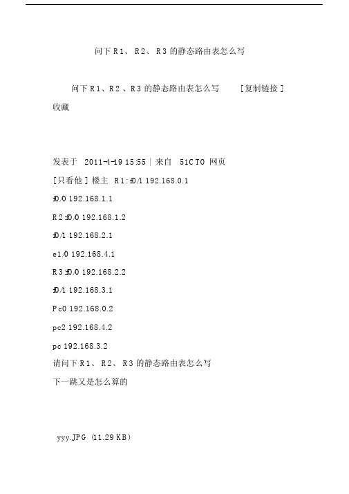
问下 R1、 R2、 R3 的静态路由表怎么写问下 R1、R2 、R3 的静态路由表怎么写[ 复制链接 ]收藏发表于2011-4-19 15:55 | 来自51CTO 网页[ 只看他 ] 楼主R1: f0/1 192.168.0.1f0/0 192.168.1.1R2:f0/0 192.168.1.2f0/1 192.168.2.1e1/0 192.168.4.1R3:f0/0 192.168.2.2f0/1 192.168.3.1Pc0 192.168.0.2pc2 192.168.4.2pc 192.168.3.2请问下 R1、 R2、 R3 的静态路由表怎么写下一跳又是怎么算的yyy.JPG (11.29 KB)2011-4-19 15:55分享到:0<!--.font_green{font-size: 12px;color:#006699;}.font_green a:link{ color:#006699; text-decoration:none;}.font_green a:visited{color:#006699; text-decoration:none;} .font_green a:hover {color:#006699; text-decoration:underline;} -->弱电安防培训 --工信部认证 | 【有奖活动】那些年我们做过的运维 | 云化的数据中心服务器怎样选择引用 /回复发表于2011-4-19 16:06 | 来自51CTO 网页[ 只看他]沙发下面的实验希望对楼主有帮忙,不过还是建议找本CCNA书看看才能理解原理知识。
实验三静态路由目的:了解为何要在路由器上增设静态路由以及静态路由的配置Router>enRouter#conftRouter(config)#hostAA(config)#A(config)#int e0进入 e0 端口A(config-if)#ip add 192.168.1.1255.255.255.0 添加 e0 口的 IPA(config-if)#no shut打开 e0 口A(config-if)#exitA(config)#int s0进入 s0 端口A(config-if)#ip add 192.168.2.1255.255.255.0 添加 s0 口的 IPA(config-if)#clock rate 56000设置时钟A(config-if)#no shut打开 s0 口A(config-if)#exitA(config)#ip route 192.168.3.0 255.255.255.0 192.168.2.2 添加静态路由 Router B:Router>enRouter#conf tRouter(config)#host BB(config)#int e0进入 e0 端口B(config-if)#ip add 192.168.3.1 255.255.255.0添加 e0 口的 IPB(config-if)#no shut打开e0口B(config-if)#exitB(config)#int s1进入 s1 端口B(config-if)#ip add 192.168.2.2 255.255.255.0添加 s1 口的 IPB(config-if)#no shu打开s1口tB(config-if)#exitB(config)#ip route 192.168.1.0 255.255.255.0 192.168.2.1 添加静态路由 PC Aip 192.198.1.2netmask255.255.255.0default getway 192.168.1.1PC Bip 192.168.3.2netmask 255.255.255.0default getway 192.168.3.1本帖最近评分记录微软狂热者无忧币+2 热心广援2011-4-20 08:35【11月20 日】安徽午饭线下第二次聚会精彩瞬间!<!--.font_green{font-size: 12px;color:#006699;}.font_green a:link{ color:#006699; text-decoration:none;}.font_green a:visited{color:#006699; text-decoration:none;}.font_green a:hover {color:#006699; text-decoration:underline;}-->弱电安防培训 --工信部认证 | 【有奖活动】那些年我们做过的运维 | 云化的数据中心服务器怎样选择引用 /回复微软狂热者版主小胖蜘蛛帖子5079精华3无忧币21509发短消息家园好友他的博客他的资源发表于2011-4-20 08:35 | 来自51CTO 网页[ 只看他 ] 板凳参考小子的实验就可以了学习是一种态度,不求一日千里,但求循序渐进<!--.font_green{font-size: 12px;color:#006699;}.font_green a:link{ color:#006699; text-decoration:none;}.font_green a:visited{color:#006699; text-decoration:none;}.font_green a:hover {color:#006699; text-decoration:underline;} -->弱电安防培训 --工信部认证 | 【有奖活动】那些年我们做过的运维 | 云化的数据中心服务器怎样选择引用 /回复 cperhero中级工程师帖子1508精华无忧币983发短消息家园好友他的博客他的资源发表于2011-4-20 17:03 | 来自51CTO 网页[ 只看他]地板大概提示一下吧route0 不知道pc1,pc2 所处网段的路由,于是要添加一条到pc1网段的路由,下一跳到route1 和自己的那个接口 ,到 pc2 的路由下一跳还是 route1 同理,route1 要添加到 pc0,pc2 的路由,下一条地址分别是 route0,route2 接口地址同理, route2 到 pc0 的下一跳是 route1,到 pc1 的下一条也是 route1 <!--.font_green{font-size: 12px;color:#006699;}.font_green a:link{ color:#006699; text-decoration:none;}.font_green a:visited{color:#006699; text-decoration:none;}.font_green a:hover {color:#006699; text-decoration:underline;}-->弱电安防培训 --工信部认证 | 【有奖活动】那些年我们做过的运维 | 云化的数据中心服务器怎样选择引用 /回复fd084中级工程师帖子777精华1无忧币3184发短消息家园好友他的博客他的资源发表于2011-4-20 17:39 | 来自51CTO 网页[ 只看他 ] 5# R1 ip route 0.0.0.0 0.0.0.0 192.168.1.2R2 ip route 192.168.0.0 255.255.255.0 192.168.1.1ip route 192.168.3.0 255.255.255.0 192.168.2.2R3 ip route 0.0.0.0 0.0.0.0 192.168.2.1 <!--.font_green{font-size: 12px;color:#006699;}.font_green a:link{ color:#006699; text-decoration:none;}.font_green a:visited{color:#006699; text-decoration:none;}.font_green a:hover {color:#006699; text-decoration:underline;} -->弱电安防培训 --工信部认证 | 【有奖活动】那些年我们做过的运维 | 云化的数据中心服务器怎样选择引用 /回复 sir_gu新新人类帖子4精华无忧币14发短消息家园好友他的博客他的资源发表于 2011-4-20 22:37 | 来自 51CTO [ 只看他 ] 6# 小子的回答很明了,看看就清楚了呀!网页引用/回复953309761新新人类帖子22精华无忧币20发短消息家园好友他的博客他的资源发表于2011-4-21 14:50 | 来自51CTO 网页[ 只看他 ] 7# 说的很细致谢谢了,学习。
- 1、下载文档前请自行甄别文档内容的完整性,平台不提供额外的编辑、内容补充、找答案等附加服务。
- 2、"仅部分预览"的文档,不可在线预览部分如存在完整性等问题,可反馈申请退款(可完整预览的文档不适用该条件!)。
- 3、如文档侵犯您的权益,请联系客服反馈,我们会尽快为您处理(人工客服工作时间:9:00-18:30)。
R1配置如下:R1#R1#conf tEnter configuration commands, one per line. End with CNTL/Z. R1(config)#R1(config)#R1(config)#hostname R1R1(config)#R1(config)#enable secret tony123R1(config)#R1(config)#username admin password admin123R1(config)#R1(config)#R1(config)#line vty 0 4R1(config-line)#R1(config-line)#password tony 123R1(config-line)#R1(config-line)#loginR1(config-line)#R1(config-line)#exitR1(config)#R1(config)#line console 0R1(config-line)#R1(config-line)#password tony123R1(config-line)#R1(config-line)#loginR1(config-line)#R1(config-line)#exitR1(config)#R1(config)#R1(config)#int f0/0R1(config-if)#R1(config-if)#ip add 12.12.12.1 255.255.255.252R1(config-if)#R1(config-if)#no shutdownR1(config-if)#R1(config-if)#*Mar 1 00:15:33.739: %LINK-3-UPDOWN: Interface FastEthernet0/0,changed state to up*Mar 1 00:15:34.739: %LINEPROTO-5-UPDOWN: Line protocol on InterfaceFastEthernet0/0, changed state to upR1(config-if)#endR1#R1#R1#R1#sh ip int brInterface IP-Address OK? Method Status ProtocolFastEthernet0/0 12.12.12.1 YES manual up upFastEthernet0/1 unassigned YES unset administratively down downR1#conf tEnter configuration commands, one per line. End with CNTL/Z.R1(config)#R1(config)#ip route 23.23.23.0 255.255.255.252 ?A.B.C.D Forwarding router's addressAsync Async interfaceBVI Bridge-Group Virtual InterfaceCDMA-Ix CDMA Ix interfaceCTunnel CTunnel interfaceDHCP Default Gateway obtained from DHCPDialer Dialer interfaceFastEthernet FastEthernet IEEE 802.3Lex Lex interfaceLoopback Loopback interfaceMFR Multilink Frame Relay bundle interfaceMultilink Multilink-group interfaceNull Null interfacePort-channel Ethernet Channel of interfacesTunnel Tunnel interfaceVif PGM Multicast Host interfaceVirtual-PPP Virtual PPP interfaceVirtual-TokenRing Virtual TokenRingXTagATM Extended Tag ATM interfacevmi Virtual Multipoint InterfaceR1(config)#ip route 23.23.23.0 255.255.255.252R1#*Mar 1 00:39:00.527: %SYS-5-CONFIG_I: Configured from console by consoleR1#conf tEnter configuration commands, one per line. End with CNTL/Z.R1(config)#ip 23.23.23.0 255.255.255.252 12.12.12.2^% Invalid input detected at '^' marker.R1(config)#ip route 23.23.23.0 255.255.255.252 12.12.12.2R1(config)#R1(config)#R1(config)#endR1#R1#*Mar 1 00:46:04.623: %SYS-5-CONFIG_I: Configured from console by consoleR1#show ip routeCodes: C - connected, S - static, R - RIP, M - mobile, B - BGPD - EIGRP, EX - EIGRP external, O - OSPF, IA - OSPF inter area N1 - OSPF NSSA external type 1, N2 - OSPF NSSA external type 2 E1 - OSPF external type 1, E2 - OSPF external type 2i - IS-IS, su - IS-IS summary, L1 - IS-IS level-1, L2 - IS-IS level-2ia - IS-IS inter area, * - candidate default, U - per-user static routeo - ODR, P - periodic downloaded static routeGateway of last resort is not set23.0.0.0/30 is subnetted, 1 subnetsS 23.23.23.0 [1/0] via 12.12.12.212.0.0.0/30 is subnetted, 1 subnetsC 12.12.12.0 is directly connected, FastEthernet0/0R1#ping 23.23.23.2Type escape sequence to abort.Sending 5, 100-byte ICMP Echos to 23.23.23.2, timeout is 2 seconds: !!!!!Success rate is 100 percent (5/5), round-trip min/avg/max = 40/51/60 ms R1#R1#R2配置如下:R2>enableR2#R2#R2#R2#R2#conf tEnter configuration commands, one per line. End with CNTL/Z.R2(config)#R2(config)#R2(config)#hostname R2R2(config)#R2(config)#R2(config)#enable secret tony123R2(config)#R2(config)#R2(config)#username admin password admin123R2(config)#R2(config)#R2(config)#line vty 0 4R2(config-line)#R2(config-line)#R2(config-line)#password tony123R2(config-line)#R2(config-line)#loginR2(config-line)#R2(config-line)#exitR2(config)#R2(config)#R2(config)#line console 0R2(config-line)#R2(config-line)#R2(config-line)#password tony123R2(config-line)#R2(config-line)#loginR2(config-line)#R2(config-line)#endR2#R2#R2#R2#R2#conf tEnter configuration commands, one per line. End with CNTL/Z.R2(config)#R2(config)#R2(config)#int f0/0R2(config-if)#R2(config-if)#R2(config-if)#ip add 12.12.12.2 255.255.255.252R2(config-if)#R2(config-if)#no shutdownR2(config-if)#R2(config-if)#endR2#*Mar 1 00:25:10.683: %SYS-5-CONFIG_I: Configured from console by consoleR2#R2#ping 12.12.12.1Type escape sequence to abort.Sending 5, 100-byte ICMP Echos to 12.12.12.1, timeout is 2 seconds:.!!!!Success rate is 80 percent (4/5), round-trip min/avg/max = 20/32/44 msR2#R2#R2#sh ip int brInterface IP-Address OK? Method Status ProtocolFastEthernet0/0 12.12.12.2 YES manual up upFastEthernet0/1 unassigned YES unset administratively down downR2#conf tEnter configuration commands, one per line. End with CNTL/Z.R2(config)#R2(config)#R2(config)#int f0/1R2(config-if)#R2(config-if)#ip add 23.23.23.1 255.255.255.252R2(config-if)#R2(config-if)#no shutdownR2(config-if)#R2(config-if)#endR2#R2#*Mar 1 00:26:51.567: %LINK-3-UPDOWN: Interface FastEthernet0/1, changed state to upR2#*Mar 1 00:26:52.287: %SYS-5-CONFIG_I: Configured from console by console*Mar 1 00:26:52.567: %LINEPROTO-5-UPDOWN: Line protocol on Interface FastEthernet0/1, changed state to upR2#R2#R2#sh ip int brInterface IP-Address OK? Method Status ProtocolFastEthernet0/0 12.12.12.2 YES manual up upFastEthernet0/1 23.23.23.1 YES manual up upR2#R3配置如下:R3#R3#R3#R3#conf tEnter configuration commands, one per line. End with CNTL/Z.R3(config)#R3(config)#R3(config)#hostname R3R3(config)#R3(config)#enable secret tony123R3(config)#R3(config)#R3(config)#username admin password admin123R3(config)#R3(config)#R3(config)#line vty 0 4R3(config-line)#R3(config-line)#password tony123R3(config-line)#R3(config-line)#loginR3(config-line)#R3(config-line)#endR3#R3#*Mar 1 00:22:01.655: %SYS-5-CONFIG_I: Configured from console by consoleR3#confConfiguring from terminal, memory, or network [terminal]?Enter configuration commands, one per line. End with CNTL/Z.R3(config)#R3(config)#line% Incomplete command.R3(config)#line console 0R3(config-line)#R3(config-line)#password tony123R3(config-line)#R3(config-line)#loginR3(config-line)#R3(config-line)#exitR3(config)#R3(config)#int f0/0R3(config-if)#R3(config-if)#ip add 23.23.23.2 255.255.255.252R3(config-if)#R3(config-if)#no shutdownR3(config-if)#R3(config-if)#en*Mar 1 00:24:21.323: %LINK-3-UPDOWN: Interface FastEthernet0/0, changed state to up*Mar 1 00:24:22.323: %LINEPROTO-5-UPDOWN: Line protocol on InterfaceFastEthernet0/0, changed state to upR3(config-if)#endR3#*Mar 1 00:24:24.923: %SYS-5-CONFIG_I: Configured from console by console R3#ping 23.23.23.1Type escape sequence to abort.Sending 5, 100-byte ICMP Echos to 23.23.23.1, timeout is 2 seconds:.!!!!Success rate is 80 percent (4/5), round-trip min/avg/max = 24/32/36 msR3#R3#R3#conf tEnter configuration commands, one per line. End with CNTL/Z.R3(config)#ip route 12.12.12.0 255.255.255.252 ?A.B.C.D Forwarding router's addressAsync Async interfaceBVI Bridge-Group Virtual InterfaceCDMA-Ix CDMA Ix interfaceCTunnel CTunnel interfaceDHCP Default Gateway obtained from DHCPDialer Dialer interfaceFastEthernet FastEthernet IEEE 802.3Lex Lex interfaceLoopback Loopback interfaceMFR Multilink Frame Relay bundle interfaceMultilink Multilink-group interfaceNull Null interfacePort-channel Ethernet Channel of interfacesTunnel Tunnel interfaceVif PGM Multicast Host interfaceVirtual-PPP Virtual PPP interfaceVirtual-TokenRing Virtual TokenRingXTagATM Extended Tag ATM interfacevmi Virtual Multipoint InterfaceR3(config)#ip route 12.12.12.0 255.255.255.252 23.23.23.1R3(config)#R3(config)#R3(config)#R3(config)#ping 12.12.12.1^% Invalid input detected at '^' marker.R3(config)#endR3#R3#R3#*Mar 1 00:43:04.647: %SYS-5-CONFIG_I: Configured from console by console R3#ping 12.12.12.1Type escape sequence to abort.Sending 5, 100-byte ICMP Echos to 12.12.12.1, timeout is 2 seconds:!!!!!Success rate is 100 percent (5/5), round-trip min/avg/max = 24/55/84 msR3#R3#至此R3-R1能互通了。
