可测量2.5米4-20mA压力传感器PA3528
压力传感器4-20mA、RS485压力变送器、模拟量压力变送器

压力传感器4-20mA 、RS485压力变送器、模拟量压力变送器压力传感器4-20mA (RS485压力变送器)是把带隔离的硅压阻式压力敏感元件封装于不锈钢壳体内制作而成。
它能将感受到的液体或气体压力转换成标准的电信号对外输出,压力传感器4-20mA (RS485压力变送器)广泛应用于供/排水、热力、石油、化工、冶金等工业过程现场测量和控制。
压力传感器性能指标:测量介质:液体或气体(对不锈钢壳体无腐蚀) 量程:0-1MPa精度等级:0.1%FS 、0.5%FS (可选) 稳定性能:±0.05%FS/年;±0.1%FS/年 输出信号:RS485、4~20mA (可选) 过载能力:150%FS零点温度系数:±0.01%FS/℃ 满度温度系数:±0.02%FS/℃ 防护等级:IP68 环境温度:-10℃~80℃ 存储温度:-40℃~85℃ 供电电源:9V ~36V DC ; 结构材料:外壳:不锈钢1Cr18Ni9Ti 密封圈:氟橡胶膜片:不锈钢316L 电缆:φ7.2mm 聚氨酯专用电缆◆标准螺纹引压测量方式。
◆ 全不锈钢结构,防护等级IP68。
◆ 测量精度高达0.1级。
◆ RS485、4~20mA 输出可选。
◆ 聚氨酯专业电缆,耐高温、耐腐蚀。
压力变送器器DATA-52系列电气连接:外形尺寸:单位:mmDATA-52系列压力传感器接口螺纹:标准M20×1.5或G1/2。
产品选型:产品型号精度 通讯接口 备注DATA-5201 0.5% RS485 1.订货时,请说明量程。
2.产品标配2米电缆,超出部分需另付费用。
DATA-5202 0.5% 4~20mA DATA-52110.1%RS485红色蓝色 黄色 白色电源+ 电源- RS485(A)输出 RS485(B)输出蓝色红色电源+ 4~20mA 输出RS485输出接线图(四线制) 4~20mA 输出接线图(两线制)DATA-52系列压力变送器DATA-52系列压力变送器。
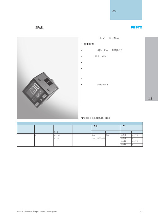
压力传感器 SPAB
传感器 压力和真空传感器
88
Sensors / Vision systems – Subject to change – 2007/10
压力传感器 SPAB, 带显示
外围元件一览
1
-V- 新产品
2
传感器 压力和真空传感器
2
5
3
4
6
1.2
附件
1 安装支架 2 前端面板安装组件 3 安全防护面板
附件
4 连接电缆 NEBU-M8…4 5 连接电缆 NEBU-L1G4,带直列式方形插座 6 快插接头 QSM-M5
订货数据 – 附件 说明 安装支架
订货号 型号 552 376 SAMH-P4-A
前端面板安装组件
552 377 SAMH-P4-F
安全防护面板
552 378 SACC-P4-G
订货数据 – 快插接头
气接口 M5
技术参数 /qsm-m5
气管外径
订货号 型号
[mm]
0 … 10 ±2%
电气参数 开关输出 模拟量输出 开关元件功能 开关功能 工作电压范围 最大输出电流 电接口
短路保护 极性容错保护 防护等级
2xPNP 或 2xNPN
1xPNP 或 1xNPN
2xPNP 或 2xNPN
1xPNP 或 1xNPN
[V]
–
1…5
–
1…5
常开或常闭触点
可自由编程
[V DC] 12 … 24
SPAB-B2R-N18-PB-K1 SPAB-B2R-N18-2P-K1 SPAB-B2R-N18-NB-K1 SPAB-B2R-N18-2N-K1 SPAB-P10R-N18-PB-K1 SPAB-P10R-N18-2P-K1 SPAB-P10R-N18-NB-K1 SPAB-P10R-N18-2N-K1
矿用本安型无线振动温度传感器参数

矿用本安型无线振动温度传感器参数下载温馨提示:该文档是我店铺精心编制而成,希望大家下载以后,能够帮助大家解决实际的问题。
文档下载后可定制随意修改,请根据实际需要进行相应的调整和使用,谢谢!并且,本店铺为大家提供各种各样类型的实用资料,如教育随笔、日记赏析、句子摘抄、古诗大全、经典美文、话题作文、工作总结、词语解析、文案摘录、其他资料等等,如想了解不同资料格式和写法,敬请关注!Download tips: This document is carefully compiled by theeditor.I hope that after you download them,they can help yousolve practical problems. The document can be customized andmodified after downloading,please adjust and use it according toactual needs, thank you!In addition, our shop provides you with various types ofpractical materials,such as educational essays, diaryappreciation,sentence excerpts,ancient poems,classic articles,topic composition,work summary,word parsing,copy excerpts,other materials and so on,want to know different data formats andwriting methods,please pay attention!矿用本安型无线振动温度传感器的技术参数解析在现代矿业中,安全和效率是两大核心要素。
菲尔斯特智慧燃气压力传感器说明书
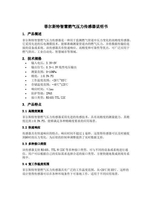
菲尔斯特智慧燃气压力传感器说明书1. 产品概述菲尔斯特智慧燃气压力传感器是一种用于监测燃气管道中压力变化的高精度传感器。
它采用先进的压电薄膜技术,能够准确测量管道内的燃气压力,并将数据传输给连接的设备或系统。
该传感器具有快速响应、高精度和可靠性等优点,可广泛应用于燃气供应、工业自动化、智慧城市等领域。
2. 技术规格•输入电压:3.3V-5V•输出信号:0.5-4.5V线性电压输出•测量范围:0-10MPa•精度:±0.5% FS•工作温度范围:-20℃~85℃•存储温度范围:-40℃~125℃•响应时间:≤1ms•防护等级:IP65•接口类型:RS485/TTL/I2C3. 产品特点3.1 高精度测量菲尔斯特智慧燃气压力传感器采用先进的传感技术,具有高精度的测量能力。
其精度达到±0.5% FS,能够满足各种精确度要求的应用场景。
3.2 快速响应传感器具有快速响应的特点,响应时间不超过1毫秒。
这使得传感器可以及时捕捉到瞬时的压力变化,为后续的控制和调整提供了实时数据支持。
3.3 多种接口类型该传感器支持RS485、TTL和I2C等多种接口类型,可与不同的设备或系统进行通信。
用户可以根据自己的实际需求选择合适的接口类型,方便快捷地集成到现有系统中。
3.4 宽工作温度范围菲尔斯特智慧燃气压力传感器具有广泛的工作温度范围,从-20℃到85℃。
这样的设计使得传感器可以在各种环境条件下可靠地工作,适用于不同应用场景。
3.5 高度可靠性产品经过严格的质量控制和测试,具有高度的可靠性。
传感器采用高品质的材料和先进的制造工艺,确保其在长期使用中性能稳定可靠。
4. 安装与连接4.1 安装要求a.安装位置应远离高温、潮湿和强磁场等干扰源;b.保持传感器与被测介质之间的密封性,防止渗漏;c.安装时避免强烈的震动和冲击。
4.2 连接方式a.将传感器的电源正极连接到电源的正极,负极连接到电源的负极;b.将传感器的信号输出线连接到接收设备或系统的对应接口上;c.注意接线的牢固性和正确性,避免接触不良导致数据传输异常。
超声波流量计 HHUF系列

超声波流量计 HHUF系列
HHUF-DF 型非满管超声波流量计
特点:
1、测量精度优于国内外同类产品
2、极强的抗电磁干扰能力,可抗变频器干扰
3、量程范围广,可自动调节量程范围,具有在线非线性校正功能
4、可实现远距离信号传输,安装、调试更加方便
5、流速测量采用外夹式安装。
外夹式适用于市政污水、工厂污水等封闭管道。
液位传感器为管道顶部安装。
原理:
非满管管内液体的流量为:Q= V〃S (其中 V —管内液体流速 S —非满管时,管内液体截面积;S为管内液位及管道内径D的函数,即: S=f(D〃h)。
其中D—管道内径,h —管内液体液位)。
利用超声波多普勒原理来测量管道内的流速V,利用超声波液位计来测量管道内液体液位h。
典型应用:
主要应用于管道内液体未充满状况下的流量测量。
市政污水、工业污水、城市排水管道、工厂排放口等封闭管道内流量的测量与监测。
超声波流量计 HHUF系列
HHUF-TG型时差固定式超声波流量计
特点:
1、测量精度优于国内外同类产品
2、极强的抗电磁干扰能力,可抗变频器干扰
3、量程范围广,可自动调节量程范围,具有在线非线性校正功能
4、可实现远距离信号传输,安装、调试更加方便
5、结构紧凑、坚固,适合于防爆区内使用
性能参数。
湿度(327k)

概述通常湿度的测量和记录都是采用人的毛发做为测量部件但是随着对传感器反应时间要求的提高以及湿度快速变化或者在25%的湿度条件以下-10温度测量条件的大量的出现极力推荐使用我们特别设计的的测量传感器PERNIX如果你希望订购PERNIX的设备请特别指明订购需额外价钱湿度计的显示表盘由镀铝材料制白底黑字PERNIX测量部件对我们的194~202和235E250无效194 订购号00.01940.100 000圆形湿度表适合与桌面和墙挂使用钩或钉住技术数据测量范围 5~100%RH, 2%的刻度精度 2.5%RH(定期校准)工作温度-60~70尺寸 102mm,35mm D重量 0.300Kg外表天蓝色暗色镀铬外壳198 订购号00.01980.100 000温湿度表由毛细管温度传感器组成的湿度指示器由于结合了这种功能你同时可以得到相对和绝对湿度也能得到温度和露点温度技术数据测量范围 5~100%RH-25~40尺寸 133mm,46mm D重量 0.500Kg精度 2.5%RH(定期校准)1K外表天蓝色暗灰色镀铬外壳201a 订购号00.02011.100 000这种湿度计可以作为多功能测量设备由测量以%为单位的相对湿度为单位的温度和以hPa为单位的饱和压力辅件用于仪器重新标订带泡沫入口的透明箔袋技术数据测量范围5~100%RH-30~50精度 2.5%RH(定期校准) 1.0K(<0),0.7K(>0)尺寸 81mm; 242mmH; 28mm D重量0.400Kg外表天蓝色暗灰色镀铬外壳201a 订购号00.02020.100 000 Lambrech Polymeter,这种温湿度表一体化仪表允许读出相对湿度绝对湿度温度露点温度饱和压力水蒸汽压力以及不饱和度PERNIX型号无效辅件技术数据测量范围5~100%RH0.1~80g/m³绝对湿度-30~50精度 2.5%RH(定期校准) 1.0K(<0),0.7K(>0)尺寸 81mm; 242mmH; 28mm D重量0.4Kg外表天蓝色暗灰色镀铬外壳204 订购号33.02020.008 000用于201a和202型号的单独配件湿度计重量 0.050Kg220F 50P 订购号00.02202.205 000杆型湿度计带PERNIX测量部件用于测量空气湿度和吸湿性材料的含水量绝对轻制金属制造带手柄防摔坏玻璃树脂视窗技术数据测量范围5~100%RH刻度2%RH精度 2.5%RH(定期校准)工作温度-60~70尺寸 118mm; 480mmL; 杆19X8mm重量0.600Kg外层天蓝色暗灰色金属杆末梢为黑色235E 250 订购号00.02350.125 000带支架的湿度计特别适合使用在不易到达的地方表面安装技术数据测量范围5~100%RH刻度2%RH精度 2.5%RH(定期校准)工作温度-60~70尺寸 120mm 法兰;共 280mm H重量0.400Kg外层天蓝色镀铬外环235 E125 订购号00.02350.112 500带支架的湿度计如同235E250,但是深度为125mm技术数据尺寸120mm 法兰;共155 mm H重量 0.300Kg空气湿度传感器800系列这些传感器被装配在我们的 PERNIX系列产品上既带本地显示也可用于在线测量电缆末梢带护套辅件1个回形针和一个六角罗冒 R 1”主要技术数据测量范围5~100%RH刻度1%RH精度 2.5%RH(定期校准)工作温度-60~70最大电流 60mA(~0.5W)尺寸共395 mm H(帽子105mm;80mmD)重量 1.500Kg外层天蓝色暗灰色镀铬外壳800 N 30 订购号00.08000.202.030技术参数电阻 50-30-50 Ohm,对数800 L0-100 订购号00.08000.201.010电阻 0-100 Ohm,线性800 MU 订购号00.08000.206 0?2 空气湿度传感器带电阻/电流转换器有两种不同的型号输出 0~20mA(0~100%RH) 订购号00.08000.206 0024~20mA(0~100%RH) 订购号00.08000.206 042详细技术数据电阻0-100 Ohm,线性工作温度范围 -30~70输出0(4)~20mA(0~100%RH),负载500 ohm工作电压24VDC,10%重量 1.600Kg空气温湿度传感器传感器 809被装备到PERNIX传感器和铂探头上现场湿度显示内置电子器件用于温湿度在线测量在设备顶部有电缆接头接头带护套(Pg16)主要技术数据湿度测量范围 5~100%RH精度 2.5%RH温度测量范围-60~70精度0.3K(0)其它工作温度范围-60~70最大电流60mA(电阻输出)10mA(温度输出)尺寸共395 mm H(帽子105mm;80mmD)重量 1.5Kg外壳天蓝色暗灰色镀铬外壳809 L100订购号00.08090.231 515详细技术参数电阻输出5-100-5 ohm,线性809L 0-100 订购号00.08090.231 010详细技术参数电阻0-100 ohm,线性809MU 订购号00.08090.266 0?2带2个R-I转换器2个不同的型号都有效输出 0~20mA(0~100%RH) 订购号00.08090.266 1024~20mA(0~100%RH) 订购号00.08090.266 142主要技术数据电阻 0-100 ohm,线性精度 2.5%RH温度0.3K工作温度范围-30~70输出0(4)~20mA(~0~100%RH和-30~40)最大负载500 ohm工作电压24VDC10%重量 1.7Kg电气传感器8091经济型订购号00.08091.000 000一体化温湿度传感器她的精巧和可靠的设计使得她同时适合使用在工业和气象应用技术数据湿度测量元器件电容测量范围 0~100%RH精度2%RH输出模拟信号0~1VDC阻抗>2000 ohm温度测量元器件 PT100测量范围-20~80精度0.1K输出0~1V其它工作温度范围-20~80工作电压10~30VDC,10%功耗大约0.8mA重量0.4Kg8092 订购号00.08092.130 402 精密的相对湿度和空气温度传感器可以高质量的使用在工业和气象场合7芯电缆对外连接湿度测量元器件电容测量范围 0~100%RH精度1%RH(5~95%RH)2%RH其它输出模拟信号0~1VDC阻抗>1000 ohm温度测量元器件 PT100测量范围-40~60精度0.3K输出 PT100其它工作电压10~30VDC,10%功耗最大2.5mA重量0.4Kg连接电缆适合传感器00.08092.130 420,包括插入式接头(母头)长度 3.3m辅件814 订购号00.08140.000 000传感器防护罩保护传感器不受日照和雨淋适合用于空气湿度传感器800和空气温湿度传感器809技术数据尺寸 170mmФ;440mmH安装方式直接安装到22mm的杆上重量 1.7Kg漆层镀铝防水海洋色8141经济型订购号00.08141.?00 000传感器防护罩保护传感器不受日照和雨淋适合用于直径小于25mm的传感器技术数据尺寸 120mmФ;160mmH重量0.6Kg漆层白色防紫外线和挤压的塑料请选择防护罩8141经济型(M1) 订购号00.08141.000 000带固定螺纹8141经济型(M2) 订购号00.08141.100 000带固定螺纹和接头32.08141.001 000适合传感器00.08281.xxx xxx8141, 经济型(M3) 订购号00.08141.300 000使用保护盒子替代了固定螺纹适合传感器00.08092.130 xxx815保护管由镀镍的铜制造成当风速超过6m/s时或者在空气极度污染的场合使用适合传感器800和809使用重量0.070Kg.干湿球湿度计706 订购号00.0706.000 0?0标准干湿球湿度计设计用于安装到设备内部RH的测量由垂直安放的水银温度计带弹簧吸出器决定温度和温度得出的参数由水平的水银温度计决定配带我们的干湿球表格771b一个吸湿管0.5m长的毛细管和两个塞子这种干湿球温湿度计仅仅在0.2刻度时有效最大/最小温度计请选择0.5K刻度订购号:00.07060.000 0200.2K刻度订购号:00.07060.000 050技术数据(706型号)干湿球温度计-30~5015mmФ;370mmL;0.06Kg最小/最大温度:刻度 0.5K,-40~40;15mmФ;290mmL;0.05Kg刻度 0.2K,-40~40;15mmФ;290mmL;0.06Kg尺寸600mmH,200mmW重量 2.4Kg漆层白色金属支架706H 订购号00.07061.000 0?0标准干湿球温湿度计如同706除了不带三角架这种这种干湿球温湿度计仅仅在0.2刻度时有效0.5K刻度订购号:00.07061.000 0200.2K刻度订购号:00.07061.000 050706a 订购号32.07060.006 050干湿球温湿度计的部件刻度 0.5K,-30~50;15mmФ;370mmL;0.06Kg1052a-1/2K 订购号32.10520.001 020最大温度计的部件刻度 0.5K,-30~50;15mmФ;370mmL;0.06Kg1052a-1/5K订购号32.10520.001 050最大温度计的部件刻度 0.5K,-30~50;15mmФ;370mmL;0.06Kg1052b-1/2K 订购号32.10520.002 020最大温度计的部件刻度 0.5K,-30~50;15mmФ;370mmL;0.06Kg1052b-1/5K 订购号32.10520.002 050最大温度计的部件刻度 0.5K,-30~50;15mmФ;370mmL;0.06Kg707 订购号32.07060.009 000最大温度计的部件重量0.600Kg740 订购号00.07400.009 000带折叠柄的可旋转干湿球温湿度计根据需要进行温湿度测量温度计容器也可作为防辐射保护配带我们的干湿球表格771b一个吸湿管0.5m长的毛细管和两个塞子技术数据温度范围 -10~60刻度 0.2K, -30~40刻度 0.2K精度0.2K尺寸305X60X20mm(HXWXD)重量 0.600Kg740a 订购号32.07400.003010用于740型号的温度计0.2K刻度741 订购号50.07400.004 000用于740的皮制包761 订购号00.07610.000 0?0渴式干湿度计简易型用于湿度和温度定义的标准设备根据DIN58661 标准制作的精密水银温度计适合与调整其它的温度和湿度产品双壁设计减少辐射影响两个温度计都必须在由吸尘器产生的2m/s的风速的空气流通下工作辅件带湿气的容器安装螺纹线性发条0.5m的毛细管参数校验证书干湿表771b塑料箱子需要另外订购请选择-5~600.2刻度订购号00.07610.000 010-30~400.2刻度订购号00.07610.000 020技术数据精度0.2K在测量范围的最大误差0.2K在任何10的范围内的最大误差0.1K尺寸90mm,420mmH,箱子420x285x100mm(LXWXH)重量设备 1.2公斤辅件 1Kg漆层白色吸出器镀铬管761a 订购号32.07610.003 010单独温度计761a 订购号32.07610.003 020单独温度计761,官方认证订购号00.07610.000 0?2渴型干湿度湿度计就如761型只是增加了官方认证证书请选择你需要的测量范围:-5~600.2刻度订购号00.07610.000 012-30~400.2刻度订购号00.07610.000 022761a官方认证订购号32.07610.003 012单独温度计,用于00.07610.000 012,-5~60761a官方认证订购号32.07610.003 022单独温度计, 用于00.07610.000 022,-30~40761e订购号32.07610.020 000手持式推荐用于移动测量用于固定测量的干湿球湿度计819 订购号00.8190.000 000干湿球湿度计特别用于户外使用空气湿度测量通过2个倾斜的铂电极这两个铂电极必须被保护不受辐射连续的气流必须从相反的方向连续通过防止外界影响技术参数测量范围依赖于外接的显示器/记录器/转换器精度0.1K在0时工作温度范围0以上供电230V AC;50Ha,160mA水柜容量150cm³重量 1.9Kg干湿度湿度表和便携计算器用测量值并且套用公式计算湿度值需要大量的时间因此图形或者数字干湿球湿度表被经常使用渴氏干湿球计算表德国气象服务编辑德国Friedrich Vieweg, Brauschweig出版我们的每个干湿球湿度都是由图形干湿球表提供在大气压1006.6hPa的情况下计算得出在某种高精度的调节需要下在有20hPa的偏差的情况下必须进行压力修正在大多数修正条件下我们提供便携计算器767和湿度计算表768G768G 订购号00.07680.030 000干湿球湿度表根据Sonntag计算曲线有详细的蒸汽压力和湿度修正应用的大气压力范围670~1065hPa曲线大小 Din A4(210x297mm)771b 订购号00.07710.020 000用于湿度计算的干湿球湿度表湿度范围0~100%RH环境温度范围0~100参考压力1006.6hPa表尺寸560X580mm767 订购号00.07670.001 000可编程便携计算器带湿度计算程序包含Sprung公式也能用于修正计算相对湿度和绝对湿度也能计算修正露点这个预设参数是在大气压力1006.6的情况用户也可根据自己的要求随意更改重量0.500Kg。
PAKU PN80数显式压力传感器说明书

PAKU PN80数显式压力传感器说明书技术参数供电电压:1230Vdc、高精度扩散硅芯。
空载电流消耗:30mA,24Vdc供电、开关输出。
输出类型:PNP、NPN可选常开常闭可设定。
S1,S2输出电流:<500mA响应时间<10ms。
开关准确度:≤士0.5%量程电流型模拟输出:≤+0.5%量程、输出类型:420m可设置、负载RA:≤0.5KOhm、线性度:≤0.5%量程、接线保护:反相,过载,短路保护显示。
设计:绝4位8mm亮度。
准确度:≤+0.5%量程、稳定性(年漂移量):≤+0.3%量程、温度:介质温度:-05.C环境温度:200°C。
储存温度:-30、80°C。
材料:表头外壳、工程塑料壳体。
不锈钢304介质接触部分:不锈钢304。
防护等级:IP67、出线方式:M12x1接插件、头部分和六角部分可330°旋转温度补偿。
PAKU流量传感器SN51B-020DP2K3Q,内螺纹:G1。
注意事项1、采用接触感温式安装时,应让产品贴紧被控器具的安装面。
2、安装时不能将塑胶或金属外壳压塌或使其变形,以免影响性能。
3、金属外壳产品有加绝缘外套的在安装中不可把外加绝缘套去掉不用或压破,避免造成漏电,确保使用安全。
4、产品在不大于5A电流的电路中使用,应选择铜芯截面为0.4--0.75㎜2导线与之连接。
5、产品应在相对湿度小于90%,环境温度40℃以下通风、洁净、干燥、无腐蚀性气体的场所中存放。
6、引线折弯运用时,应从间隔根部6毫米以上的部件折弯;折弯时,不得损害根部和引线,不得强行牵拉、按压、扭拧引线。
7、热熔断体选用螺钉、铆接或接线柱固定方法时,应能防止机械蠕变而千万触摸不良现象的发生。
8、连接部件应可以在电器产品作业范围内可靠地作业,不会因振动、冲击而发生位移。
引线焊接作业时,应将加热湿度束缚在小,留心不得在热熔断体上外加高温;不得强行牵拉、按压、扭拧热熔断体和引线;焊接完毕后,应立即冷却30秒以上。
XSAV11374传感器说明
XSAV11374传感器说明施耐德接近开关XS218BLNAL2C,XS218BLPAL2C,XS118BLPAL2C,XS118BLPAL2C,XS218BLNAL2C,XS218B LPAL2C,XS118BLPAL2C,XS118BLNAL2C咨询乐清市慈豪电气有限公司/唐经理,大量库存XS218BLNAL2C施耐德接近开关M18三线NPN常开XS218BLNAL2C/XS230BLNAL2C施耐德接近开关主要由感应型,光电型,静电型,超声波型,磁力型等组成。
无需接触检测对象进行检测为目的,达到对检测对象移动信息和存在信息转为电气信号,在换为电器信号的检测方式中,包括利用电磁感应引起的检测对象的金属体中产生的涡电流的方式,捕测体的接近引起的电气信号的容量变化的方式,利石和引导开关的方式。
根据iec60947-5-2的非接触式位置检测用开关,在传感器以非接触方式检测到物体的产品为接近开关。
XS208BLNAL2C工业接近传感器商品描述:XS1工业接近传感器金属圆柱型1标称感应距离Sn (20°C, mm) 1.5 2.5 2 42金属中的安装形式:埋入式非埋入式3外壳M (金属) P (塑料):M4工作温度范围(°C):- 25 ~ + 705防护等级(符合IEC 529):IP676开关容量(mA):5 ~ 2007工作电压(V)包括电压波动:20 ~ 2648开关频率(Hz):25(1) 需配备0.8 A的快熔保险丝与负载串联施耐德工业接近传感器型号:XS106BLPAL2,XS106BLPBL2,XS108BLPAL2C,XS108BLPBL2C,XS106BLNAL2,XS108BLNAL2C,XS106BLNBL2,XS108BLNBL2CXS208BLPAL2C,XS208BLNAL2C,XS208BLNBM12C,XS208BLNAM12C,XS208BLNBL2C,XS208BLPBL2C,XS208BLPAM12C,XS208BLPBM12C,XS108BLPAM12C XS108BLPBM12C,XS108BLNAM12C,XS108BLNBM12C XS208BLPAL2C,XS208BLPBL2C,XS208BLPAM12CXS208BLPBM12C,XS208BLNAL2C,XS208BLNBM12C XS208BLNAM12C,XS208BLNBL2C,XS112BLPAL2C,XS112BLPBL2C,XS112BLNAL2C,XS212BLNAL2CXS112BLNBL2C,XS212BLNBL2C,XS212BLPAL2CXS212BLPBL2C,XS212BLPAM12C,XS212BLPBM12CXS212BLNAM12C,XS212BLNBM12C,XS112BLFAL2XS118BLPAL2C,XS118BLPBL2C,XS118BLNAL2CXS218BLNAL2C,XS130BLNAL2C,XS230BLNAL2CXS8S173NAL2C,XS8S174NAL2C,XS118BLNBL2C,XS218BLNBL2C,XS130BLNBL2C,XS230BLNBL2C,XS8S173NBL2C,XS8S174NBL2C,XS218BLPAL2CXS218BLPBL2C,XS218BLPAM12C,XS218BLPBM12CXS130BLPAL2C,XS130BLPBL2C,XS218BLNAL2C,XS130BLNAL2C,XS230BLNAL2C,XS8S173NAL2CXS8S174NAL2C,XS118BLNBL2C,XS8S173NBL2CXS8S174NBL2C,XS118BLNBM12C,XS218BLNBM12C XS130BLNBM12C,XS230BLNBM12C, XS118BLNAM12C,XS218BLNAM12C,XS130BLNAM12C, XS230BLNAM12CXS218BLNBL2C,XS130BLNBL2C,XS8S174PBL2CXS230BLPAL2C,XS8S174PAL2C,XS8S174NAL2CXS230BLPBL2,XS8S173PBL2C,XS230BLPBM12C, XS118BLFAL2, XS130BLFAL2我公司代理经销:施耐德(TE)、欧姆龙(OMRON)、西门子(SIEMENS)、ABB、产电(LS)、倍加福(P+F)、图尔克(TURCK)、奥托尼克斯(AUTONICS)、常熟开关、上海人民、天水二一三等品牌元器件.经营范围:低压电器(接触器、继电器、热过载继电器、按钮等)(微型断路器、塑壳断路器、框架断路器、双电源开关、开关、负荷开关、浪涌保护器、熔断路等)传感器(接近开关、光电开关、限位开关、微动开关、行程开关)。
久茂自动化(大连)有限公司 403023 JUMO dTRANS p20 DELTA Ex d 压差

JUMO dTRANS p20 DELTA Ex d带防爆外壳的差压变送器简述JUMO DTRANS P20 Delta Ex d 压差变送器集最大精度和简单操作于一体,用于测量气体、蒸汽 和液体的压差。
集成液晶显示屏显示测量值和设备数据。
防爆型“Ex ia (本安型)”允许设备安装到0区。
外壳和传感器由高级不锈钢制成。
隔膜密封也可用于特定工艺技术应用(见数据单409772 至409784)。
该设备具有可编程性,因此很容易适应各种不同的测量任务。
一个易于使用的设置程序作为附件, 可通过接口启动操作。
旋转按键使现场手动操作非常方便快捷。
根据2.0版DIN EN 61508/-1/-2,对具有4至20 mA 和HART®协议的压力变送器进行安全功能评 估,并由T ÜV Nord 认证。
这些测量设备适用于监测过程液位和压力,最高可达SIL2。
更多详情请参见安全手册。
“Ex ia ”防爆版本见数据表403022。
有关表压和绝压版本,请参见数据表403025和403026。
型号 403023流程图特点• 不锈钢外壳• SIL 认证(T ÜV Nord) • HART ®接口• 防爆 Ex d (气体和灰尘) 参考 ATEX 和EAC • 线性度 0.07 % • 带旋转按键使操作简单 • 设置程序• 带条形图的LCD 显示屏 • 显示选择测量单元 • 显示传感器温度 • 显示最大最小压力 • 电流发生器功能• 特征线和显示器也可用于调节测量流量认证/认证标识(见"数据单")数据单基本信息b JUMO接口不得用于潜在爆炸区域!在这种情况下,可通过旋转按键或HART®接口操作输入输出电源电源DC 12 至 36 V 机械特性环境条件b 在-40至-50°C范围内,设备必须持续运行。
此外,设备带有检查玻璃的盖子是为了防止机械冲击和冲击效应。
美国 MEAS传感器 说明书

工业机器和设备应用
生产过程控制,阀门和流量控 制,气缸控制,网前箱(纸和 纸浆) 校巴停靠信号控制 空压机控制,喷涂设备,闭环 反馈,泵控系统,恒压供水 手持式压力表,气相色谱仪 机械人, 称重, 产品验证 冲压机动荷载测力器
测试与测量仪器
测试与测量仪器需要高精度、高 稳定的传感器。由于Schaevitz®, ATEX和Entran®优异的品质使得美国 MEAS传感器一直是那些追求高精度 传感器客户的理想供应商。最近,美 国MEAS传感器在芯片稳定性方面的 改进,使超稳压力传感器和超稳压力 变送器跻身于特殊环境下的测试与测 量等应用领域。
位移和倾角传感器 运动传感器 Humirel 相对湿度传感器
热电堆 热敏电阻
运动传感器 声学传感器 振动传感器 超声波传感器 数字按键键盘 血氧探头 (SPO2)
医疗应用
一次性血压传感器,通风设备, 呼吸器,睡眠呼吸暂停传感器,
气压表,监护仪,麻醉机,呼吸机 注射泵,球囊成形术,眼外科, 低温成形术,脊柱测试
产线
位置
位置 位置
压力 压力 湿度 温度
振动 振动
振动 压电薄膜 力
传感器/产品类型
Schaevitz®LVDT、角 位 移 传 感器 Schaevitz®RVIT传感器 不锈钢隔离式压力变送器 (充油型)
板装式压力传感器 不锈钢隔离式压力传感器 (充油型) 相对湿度和温度传感器 NTC热敏电阻
加速度计
非破坏性测试 汽车安全带拉力, 称重和测量
工业解决方案 商业建筑和设备
美国MEAS传感器可为商业建筑业厂家提供服务,尤其是在供暖、通风和制冷领域。由 于我们的全密封结构微熔技术压力传感器可在恶劣环境中正常工作,故该产品为暖通、空调 和制冷厂家提供了理想的解决方案。
Yokogawa TX1500 系列4-20mA隔离传感器接收器说明书
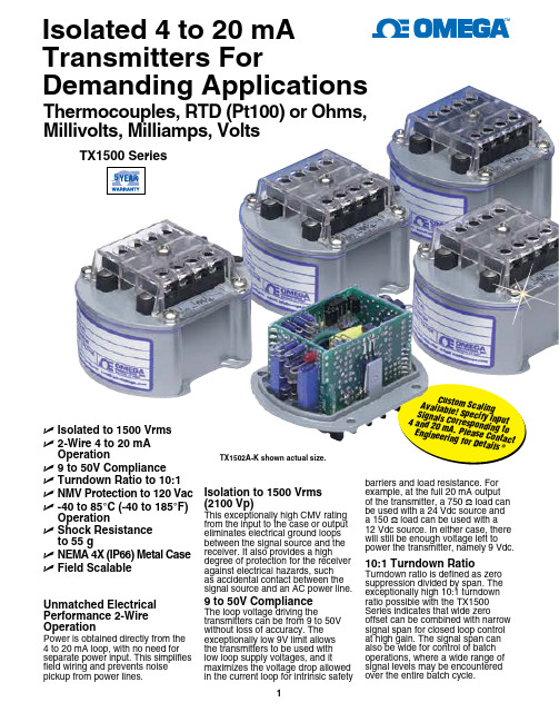
Isolated 4 to 20 mA Transmitters ForDemanding ApplicationsU Isolated to 1500 Vrms U 2-Wire 4 to 20 mA OperationU 9 to 50V Compliance U Turndown Ratio to 10:1U NMV Protection to 120 Vac U -40 to 85°C (-40 to 185°F) Operation U S hock Resistance to 55 g U N EMA 4X (IP66) Metal Case U Field Scalable TX1502A-K shown actual size.barriers and load resistance. For example, at the full 20 mA output of the transmitter, a 750 Ω load can be used with a 24 Vdc source and a 150 Ω load can be used with a 12 Vdc source. In either case, there will still be enough voltage left to power the transmitter, namely 9 Vdc.10:1 Turndown RatioTurndown ratio is defined as zero suppression divided by span. The exceptionally high 10:1 turndown ratio possible with the TX1500 Series indicates that wide zerooffset can be combined with narrow signal span for closed loop control at high gain. The signal span can also be wide for control of batch operations, where a wide range of signal levels may be encountered over the entire batch cycle.Isolation to 1500 Vrms (2100 Vp)This exceptionally high CMV rating from the input to the case or output eliminates electrical ground loops between the signal source and the receiver. It also provides a highdegree of protection for the receiver against electrical hazards, such as accidental contact between the signal source and an AC power line.9 to 50V Compliance The loop voltage driving thetransmitters can be from 9 to 50V without loss of accuracy. The exceptionally low 9V limit allows the transmitters to be used with low loop supply voltages, and it maximizes the voltage drop allowed in the current loop for intrinsic safetyCu st o m S c a l i n g A v a i l a b l e ! S p e c i f y I n p u tS i g n a l s C o r r e s p o n d in g t o 4 a n d 20 m A . P l e a s e C o n t a c t E n g i n e e r i n g f o rD e t a i l s®Thermocouples, RTD (Pt100) or Ohms, Millivolts, Milliamps, VoltsUnmatched Electrical Performance 2-Wire OperationPower is obtained directly from the 4 to 20 mA loop, with no need for separate power input. This simplifies field wiring and prevents noise pickup from power lines.TX1500 Series5High Overvoltage Protection Overvoltage of 120 Vac may be applied across the input or output leads for 1 minute for all models with voltage or thermocouple inputs. Reverse polarity of 400 Vp maybe applied across the output leads indefinitely. These exceptionally high NMV overvoltage ratings provide further protection against possible electrical faults and wiring errors.Designed for Harsh EnvironmentsExtreme operating temperatures. The operating temperature can range from -40 to 85°C (-40 to 185°F) while meeting published performance specifications. This allows the TX1500 Series to be used near furnaces or outdoorsin the winter. The exceptionally wide operating temperature range is made possible by a proprietary electrical circuit and by extensive use of computer-graded and computer-matched electrical components.Resistance to shock and vibration. The shock rating is 55 g (1.9 oz), which includes a 1.8 m (6') drop onto concrete. This is made possible by a compact die-cast metal case, which is only 74 mm (2.9") indiameter, and by rugged mountingof the electronics. The circuit boardassembly is in the shape of a rigidbox and is firmly soldered to the topof the transmitter case.Waterproof CaseThe case is made of diecast zincalloy. It is waterproof to 35 kPa(5 psi) and meets NEMA 4X (IP66)standards. The top of the caseis sealed against the bottom witha fluorosilicone gasket, and theopenings in the top of the case forthe zero and span adjustment, aresealed with fluorosilicone plugs.Explosion-ProofHousing OptionsThree external NEMA 7explosion-proof and NEMA 4 (IP65)waterproof, sand-cast, copper-freealuminum enclosures withcorrosion-resistant “safety-blue”polyester powder-coating for use inhazardous locations. FM, UL, cULCertification: Class I, Groups B, C,D; Class II, Groups E, F, G; andClass III, Type 4X. Demko/ATEXCertification: EX II 2 G D EEx d IIC.Option EPH1-ATEX is a single-height, all-metal housing for a singleTX1500 Series transmitter.Option EPW2-ATEX is a double-height metal enclosure with aglass window for a TX1500 Seriestransmitter on the bottom and aTX83A loop-powered indicator on top.The TX83A augments the transmitterwith an LCD digital readout scaled inengineering units and only adds a 2.5V drop to the current loop.Option EPW3-ATEX is a single-height enclosure for one TX83Aloop-powered indicator. Thisoption includes 2 female 1⁄2 NPTpipe fittings, all required internalmounting hardware, and mountingflanges for a wall or bulkhead.Easy to Calibrate and InstallThere is no need to specify differentmodels for different ranges of thesame signal type. Zero and spanare each set by push-on jumpersfor coarse range selection and bya 15-turn precision potentiometer forfine adjustment. The 2 potentiometersare accessible outside the casethrough openings that are normallysealed by fluorosilicone plugs. Toassist in calibration, 2 test terminalsprovide a 10 mV/mA output (200 mVfull scale). The scaling procedure isexplained in a comprehensive user’smanual, which is shipped with everyunit.EnvironmentalOperating Temperature: -40 to 85°C (-40 to 185°F)Storage Temperature: -55 to 125°C (-67 to 257°F)Relative Humidity: 0 to 100% (sealed case)Watertight Proof Pressure: 35 kPa (5 psi)Shock: 55 g, half sine, 9 to 13 ms duration Vibration: 1.52 mm (0.06") double amplitude, 10 to 80 Hz cycledMechanicalCase Material: Zamak zinc alloy Gasket Material: Fluorosilicone Diameter: 74 mm (2.9")Height, Including Barriers: 53 mm (2.1")Weight: 380 g (13 oz)Electrical Connection: #6 screws with wire clamps Terminal Protection: Standard: Screw terminal barriers plus barrier strip cover CPB1 (Optional): Plastic cover for case top (protects T/C screw terminals from air currents)Common SpecificationsSignal OutputConnection: 2-wireLinear Range: 4 to 20 mA Maximum Output: 35 mAVoltage Compliance: 9 to 50 VdcPower Supply Rejection: 0.01% of span/V Input/Output Protection:CMV, Input to Case or Output: 2100 Vp per HV test, 354 Vp per IEC spacingCMR, Input to Case or Output:120 dB, DC to 60 Hz NMV Across Output Leads: 120 Vac for 1 min Reverse Polarity Across Output Leads: 400 VpAccuracy: -40 to 85°C (-40 to 185°F)Hysteresis and Repeatability: ±0.1% of span 6-month Stability Error: ±0.2% of zero suppressionError Due to 50°C Change in Transmitter Temperature:Zero Error: ±0.2% of zero suppression Span Error: ±0.2% of spanTX1501 shown smaller than actual size..Non-Common SpecificationsRTD InputModel TX1501Signal Source: Pt100 RTDSpan for 4 to 20 mA Output:100 to 1050°C (180 to 1890°F)Zero Suppression:-200 to 750°C (-328 to 1382°F)Source Connection: 2- or 3-wireExcitation Current: 200 µALead Resistance, Max: 100 ΩBandwidth: DC-60 HzOhms InputModel TX1501Signal Source: 0 to 400 ΩSpan for 4 to 20 mA Output:35 to 400 ΩZero Suppression: 0 to 365 ΩSource Connection: 2- or 3-wireExcitation Current: 200 µALead Resistance, Max: 100 ΩBandwidth: DC-60 HzThermocouple InputModel TX1502ASpan and Zero Suppression:See input tableInput Resistance (Open T/C DetectorResistance): 5 MΩBias Current, Max: 50 nANMV Across Input Leads:120 Vac for 1 minNMR Across Input Leads:40 dB, 50/60 Hz, 100 mV inputThermocouple Lead Resistance:For specified performance: 100 ΩMaximum: 10 kΩStep Response, Type: 400 msMillivolt InputModel TX1504Span for 4 to 20 mA Output:5 to 100 mVZero Suppression: -30 to 60 mVInput Resistance: 100 MΩBias Current, Max: 50 nANMV Across Input Leads:120 Vac for 1 minNMR Across Input Leads: 40 dB,50/60 Hz, 100 mV inputStep Response, Type: 400 msMilliamp InputModel TX1505Span for 4 to 20 mA Output:5 to 100 mAZero Suppression: -30 to 60 mAInput Resistance: 1 ΩStep Response, Type: 400 msVolt InputModel TX1506Span for 4 to 20 mA Output:0.5 to 5 V (TX506-1); 5 to 50V(TX506-2)Zero Suppression:-3.5 to 6.0 V (TX506-1); -35 to 60V(TX506-2)Input Resistance: 1 MΩBias Current, Max: 1 nANMV Across Input Leads:120 Vac for 1 minNMR Across Input Leads:40 dB, 50/60 Hz, 100 mV inputStep Response, Type: 400 msfor a maximum loop drop of 0.1 V at 20 mA. DP41 meters are available with dual or quad relay output for control or alarm.500 Series Low Cost PM LineartA Model DP24, DP25 or DP41 panel meter may be used to powerthe 4 to 20 mA loop, including the isolated 2-wire transmitter. One ofmore loads may be added to the loop, including receiving equipmentin the control room. The excitation supply is electronically floating, so that the current loop may be grouded anywhere. In addition to powering the loop, the panel meter provides a local display scaled in percent or in engineering units.A DP24, DP25 or DP41 panel meter may be used to power the 4 to 20 mA loop, including the isolated 2-wire transmitter. One or more loads may be added to the loop, including receiving equipment in the control room. The excitation supply is electronically floating; thus, the current loop may be grounded anywhere. In addition to powering the loop, the panel meter provides a local display scaled in percent or in engineering units.Adding Digital Panel Meters to a 4 to 20 mA LoopOne or more digital panel meters may be added to a 4 to 20 mA loop for local readout in percent or engineering units, without degrading the accuracy of the 4 to 20 mA signal. OMEGA’s TX83A and TX82B loop-powered indicators derive all operating power from the loop itself, with a maximum loop drop of 2.5 V. The use of such indicators simplifies field wiring. OMEGA’sDP41 meters insert a loop resistance of only 15 Ω for a maximum loop drop of 0.1 V at 20 mA. DP41 meters are available withdual or quad relay output for control or alarm.TX1502A-J shownsmaller than actual size.TX1504 (customer will calibrate for 0 to 50 mVdc = 4 to 20 mA). TX1502A-K-FS (0 to 100°C = 4 to 20 mA). TX1505-FS (5 to 12 mA = 4 to 20 mA).TX1504 shown smaller than actual size.。
浙江渤海电器有限公司 A200358 产品说明书

Installation InstructionsNOTE: Read the entire instruction manual before starting the installation.A200358SAFETY CONSIDERATIONSImproper installation, adjustment, alteration, service, maintenance, or use can cause explosion, fire, electrical shock, or other conditions which may cause death, personal injury or property damage. Consult a qualified installer, service agency, or your distributor or branch for information or assistance. The qualified installer or agency must use factory-authorized kits or accessories when modifying this product.Refer to the individual instructions packaged with kits or accessories when installing.Follow all safety codes. Wear safety glasses, protective clothing and work gloves. Have a fire extinguisher available. Read these instructions thoroughly and follow all warnings or cautions included in literature and attached to the unit. Consult local building codes and the current editions of the National Electrical Code (NEC) NFPA 70.In Canada, refer to the current editions of the Canadian Electrical Code CSA C22.1.Recognize safety information. This is the safety-alert symbol . When you see this symbol on the unit and in instruction manuals, be alert to the potential for personal injury.Understand the signal words DANGER, WARNING, and CAUTION.These words are used with the safety-alert symbol. DANGER identifies the most serious hazards which will result in severe personal injury or death. WARNING signifies hazards which could result in personal injury or death. CAUTION is used to identify unsafe practices which may result in minor personal injury or product and property damage.NOTE is used to highlight suggestions which will result in enhanced installation, reliability, or operation.IntroductionThe purpose of this kit is to add a directional-flow air diffuser to the exhaust opening of the OptiClean™ Air Scrubber.Description and UsageThe Accessory Air Diffuser consists of:•pre-assembled diffuser with internal 1ʺ foil-faced insulation •hardware bag with self-tapping screws and instructions.Installation1.Turn off all electrical supply to the unit.2.Remove the assembled diffuser and hardware bag from the carton.3.If the factory supplied duct transition has been installed on the unit’s exhaust opening, remove and store or discard. Only a duct transition or a diffuser should be installed.4.Position the diffuser over the unit's exhaust opening flanges.5.Attach the diffuser to the flanges with the provided hardware.6.Restore power to the unit.KFADG0101SML / KFADG0101LRGAccessory Air Diffuserfor use with OptiClean™ Air Scrubber Model FN1AAFPart Number Use With Scrubber Model Carton Dimensions – in.KFADG0101SML FN1AAF005FN1AAF00617.875 x 11.625 x 20.25KFADG0101LRGFN1AAF01526 x 21 x 13WARNING!ELECTRICAL OPERATION HAZARDFailure to follow this warning result in personal injury or death.Before installing or servicing unit, always turn off all power to unit.There may be more than 1 disconnect switch.WARNING!MOVING PARTS & SHARP EDGES HAZARDFailure to follow this warning could result in personal injury.Wear gloves when handling.Keep hands and face away.Do not place objects on top of the discharge plenum.Avoid rotating blower wheel, which can cause serious injury.Do not allow unsupervised children to play near the unit.CAUTION!CUT HAZARDFailure to follow this caution may result in personal injury.Sheet metal parts may have sharp edges or burrs. Use care and wear appropriate protective clothing, safety glasses and gloves when handling parts.© 2020 Carrier. All rights reserved.A Carrier CompanyEdition Date: 08/20Catalog No: IIK-KFADG-01Replaces: NewKFADG0101SML / KFADG0101LRG: Installation InstructionsManufacturer reserves the right to change, at any time, specifications and designs without notice and without obligations.2A200349Fig. 1 – Dimensions (KFADG0101LRG shown)Table 1 – Dimensions — in. (mm)Model A B C D E Outlet Grille Size KFADG0101SML 16.04 (407)17.44 (443) 3.50 (89)11.21 (285) 3.28 (83)12 x 8 (305 x 203)KFADG0101LRG19.56 (497)22.32 (567)4.50 (114)11.25 (286)1.06 (27)16 x 16 (406 x 406)E。
迪迪电子 4-20mA压力传感器说明书

To Order
GAGE PRESSURE RANGES
psi
bar
MODEL NO.
0 to -14.7 0 to 1 0 to 6 0 to 15 0 to 30 0 to 60 0 to 100 0 to 150
0 to -1.0 0 to 0.0689 0 to 0.414 0 to 1.0 0 to 2.1 0 to 4.1 0 to 6.9 0 to 10.3
Total Error Band: 1% FS (includes temperature effects within compensated temperature range)
Operating Temperature: -40 to 80°C (-40 to 176°F)
Compensated Temperature: -25 to 75°C (-13 to 167°F)
0 to 200
0 to 13.8
PX182B-200GI DP24-E, DP25B-E, DP41-E, DPi Series
SPECIFICATIONS
Excitation: 11 to 30 Vdc
Output: 4 to 20 mA (2 wire)
Accuracy: 0.3% BFSL maximum (includes linearity, hysteresis and repeatability)
The PX182B is fully digitally compensated for the effects of pressure and temperature change. It is extremely accurate, with less than 0.3% FS reference accuracy and less than 1% FS over its compensated temperature range.
Belimo 22ADP-156 压差传感器说明书

22ADP-156..压差传感器带有可选8个不同的测量范围及Modbus通讯方式的压差变送器。
主要监测空气及其他非可燃性、非腐蚀性气体的压差值,可用于空气过滤网、风机、工业制冷空调系统、风阀与防火阀的控制等场合。
可选带LCD显示功能防护等级:IP65/NEMA 4X型号概览型号 输出信号 压力测量范围显示类型22ADP-156Modbus0...7000 Pa-22ADP-156L Modbus0...7000 Pa LCD显示技术参数电气参数供电电源 DC15...24 V, ±10%, 1.4 W供电电源 AC24 V, ±10%, 2 VA电气接线可拆卸弹簧加载端子排,最大2.5 mm²线缆连接2xØ6mm M20电缆戈兰头, 带2xØ6mm防拉扣功能参数传感器技术压电式测量元件通讯Modbus RTU多量程是压力有源输出信号ModbusDC 0...10 V4...20 mA输出有源信号可通过开关选择DC 0...5/10V输出最小负载10 kΩ最小负载 500 Ω显示LCD显示, 37.5 x 31.6 mm测量值: Pa, inchWC, mmWC, kPa, mbar,psi(可修改)介质空气测量数据测量值压差测量介质空气和非腐蚀性气体设置压力测量范围设置范围 [Pa]范围 [inch WC]工厂设置S00...70000 (28)S10...50000 (20)S20...40000 (16)S30...30000 (12)S40...25000 (10)S50...20000 (8)S60...15000 (6)S70...10000 (4)压力测量精度偏差(与基准设备比较)量程 ≤2000 Pa时: ±10 Pa量程 >2000 Pa时 : ±25 Pa材质线缆接头PA6, 黑色外壳顶盖: 聚碳酸酯,NCS S0580-Y6OR(搏力谋橙)底座: 聚碳酸酯,NCS S0580-Y6OR(搏力谋橙)密封: NBR70,黑色22ADP-156..安全提示环境湿度95%相对湿度,无结露环境温度-10...50°C [14...122 °F]IEC/EN防护等级防触电保护等级:III (安全低压)NEMA/UL 防护等级UL Class 2EU联合CE MarkingIEC/EN认证IEC/EN 60730-1 和 IEC/EN 60730-2-6UL认证申请中IEC/EN防护等级IP65NEMA/UL 防护等级NEMA 4X 质量标准ISO 9001重量0.150 kgSafety notes只有经过专业培训的工作人员可以安装此产品及相应附件该产品只能用于规定的应用范围。
富士智能压力变送器

环境中保护传感器。 更加小型化 , 易于现场的设置和操作。 虽然缩小了体积 , 而温度特性、 静压特性、 过压特性比传统 产品更优异。
硅微电容传感器 �� �� 低压侧充罐液 陶瓷 高压侧充罐液
低压侧压力 管道
高压侧压力 金属通孔 静电电容测量电极 硅膜片 �� ��
直接安装型 T 型壳体
压力变送器 绝对压力变送器 差压变送器
压力变送器
绝对压力变送器
压力变送器
绝对压力变送器
差压变送器
液 位 计 、毛 细 管 型 、等 品 种 丰 富 , 系 列 齐 全
液位变送器
毛细管型压力变送器
毛细管型差压变送器
小口径液位变送器
小口径毛细管型压力变送器
小口径毛细管型差压变送器
符 合 各 种 国 际 标 准 、国 际 认 证
43796301
主要规格
差压 ( 流量 ) 变送器 型号 选型资料编号 FK C CDS6-134 CDS6-135 1 6 32 130 500 3000 20000 3.1
压力变送器 FK G CDS5-92 CDS5-93 130 500 3000 10000 50000
设备管理 ● 设备诊断 ● 校正 ● 维护、保养
现场管理工具 FDT/DTM ※ 2(预定近期发售)
Foundation ■ FCX-AⅢ 系列变送器的 HART、 Fieldbus、 Profibus 各种通信均支持标准规格 的现场设备管理工具 FDT/DTM。本公司的 FDT/DTM 具有以下功能。 ・参数设定 ・量程设定 ・过程数据显示 ・故障信息收集、 诊断 ・趋势显示等
QQ:785087035
Huba压力传感器

Installation arrangement
Unrestricted
Signal/Power supply
See order code selection table • Short circuit-proof and protected against polarity reversal. Each connection against other with max. +/– supply voltage. Electric strength 500 VDC, on request 1000 VDC
Order code selection table
EDITION 03/2004
. 511
XXXXXXXXXX
Relative pressure
苏州迅鹏进口仪表事业部 9
Absolute pressure
8
Pressure ranges in bar1 –1 ... + 0 bar 0 ... + 1 bar 0 ... + 1.6 bar 0 ... + 2.5 bar 0 ... + 4 bar 0 ... + 6 bar 0 ... + 10 bar 0 ... + 16 bar 0 ... + 25 bar 0 ... + 40 bar 0 ... + 60 bar 0 ... + 100 bar 0 ... + 160 bar 0 ... + 250 bar 0 ... + 400 bar 0 ... + 600 bar
Adjustment accuracy zero point and
耐高温压力传感器
sure d 500 Strai n (με) 400
80
300
EFPI
300
RSG
400 500 600
200
Time (seconds)
图 3-12 被电子应变计校准后的珐 珀腔的应变特性
图 3-13 校准后珐 -珀腔和电子应变计的 测试结构对比
图3-12中的曲线示意的是研究标准具传感器长期稳定性和准确性的结果 。将一个恒定的应变施加到标准具上,保持~1小时,发现从标准具得到 的应变波动为~±1μ ε 。从CSM-1测量仪得到的数据是在通过一个低通滤 波器后记录的。通过F-P标准具和电阻应变仪测得的应变如图3-13。在图 3.13的图是从0 到 80s的应变测量结果的一个特写。从中可以看出标准 具和电阻应变仪的应变测试结果有很好的一致性。
高温温度和应变同时测量
该F-P标准具的准静态应变响应也可以通过将其粘接在悬臂梁(BDQ -1D, Hengxin Electronic Inc.)上来测试,悬臂梁是由不锈钢制作用来对由 于存在边缘效应引起的应变系数进行校正。该悬臂梁是等重的应变梁。 为了对光纤标准具测得的 应变进行校正,这里在梁的反面即光纤的下面安装了一个电阻应变仪 (BX-120, Huangshi Inc.),如图3-11所示。
Tunable PD Laser Agilent 81642A 2
封闭式微光纤珐-珀传感器的应变特性 ——动态应变特性
Tunable Laser Agilent 81642A gilent 81642A
1:99 Coupler 1:1 Coupler
F-P Al Agilent Dynamic Signal Analyzer PD1
0.2
Alphasense有毒气体传感器4-20mA变送器用户手册说明书
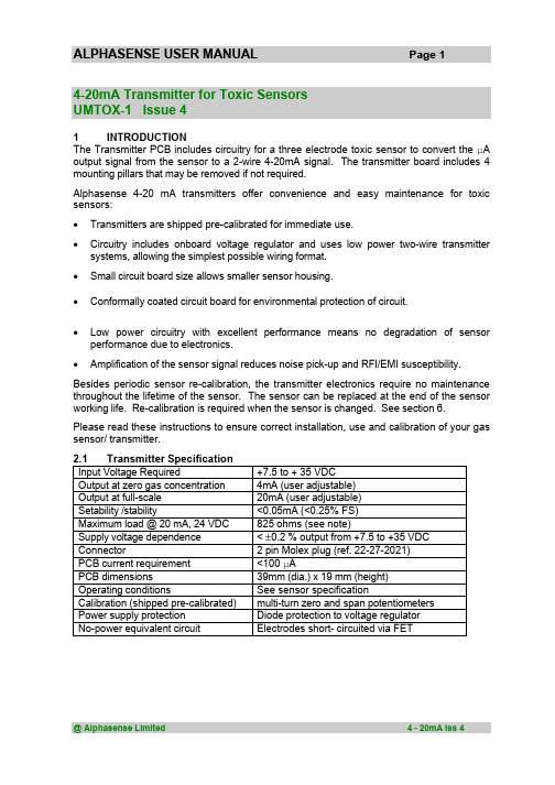
ALPHASENSE USER MANUAL Page 14-20mA Transmitter for Toxic SensorsUMTOX-1 Issue 41INTRODUCTIONThe Transmitter PCB includes circuitry for a three electrode toxic sensor to convert the µA output signal from the sensor to a 2-wire 4-20mA signal. The transmitter board includes 4 mounting pillars that may be removed if not required.Alphasense 4-20 mA transmitters offer convenience and easy maintenance for toxic sensors:• Transmitters are shipped pre-calibrated for immediate use.• Circuitry includes onboard voltage regulator and uses low power two-wire transmitter systems, allowing the simplest possible wiring format.• Small circuit board size allows smaller sensor housing.• Conformally coated circuit board for environmental protection of circuit.• Low power circuitry with excellent performance means no degradation of sensor performance due to electronics.• Amplification of the sensor signal reduces noise pick-up and RFI/EMI susceptibility. Besides periodic sensor re-calibration, the transmitter electronics require no maintenance throughout the lifetime of the sensor. The sensor can be replaced at the end of the sensor working life. Re-calibration is required when the sensor is changed. See section 6.Please read these instructions to ensure correct installation, use and calibration of your gas sensor/ transmitter.2.1Transmitter SpecificationInput Voltage Required+7.5 to + 35 VDCOutput at zero gas concentration4mA (user adjustable)Output at full-scale20mA (user adjustable)Setability /stability<0.05mA (<0.25% FS)Maximum load @ 20 mA, 24 VDC825 ohms (see note)Supply voltage dependence< ±0.2 % output from +7.5 to +35 VDCConnector 2 pin Molex plug (ref. 22-27-2021)PCB current requirement<100 µAPCB dimensions39mm (dia.) x 19 mm (height)Operating conditions See sensor specificationCalibration (shipped pre-calibrated)multi-turn zero and span potentiometersPower supply protection Diode protection to voltage regulatorNo-power equivalent circuit Electrodes short- circuited via FETUMTOX-1Page 22.2Range/OptionsSensor and transmitter boards are shipped from Alphasense pre-calibrated. You may wish to confirm calibration. Standard available ranges are listed below:Sensor Ordering Code(includes sensor)Full-Scale Gas Concentration(ppm)Gain CO-BF THCO-BF 1000Low CO-BF TLCO-BF 100High H2S-BE THH2S-BE 1000Low H2S-B1THH2S-B1200Low H2S-B1TLH2S-B125High SO2-BF THSO2-BF 100Low SO2-BF TLSO2-BF 20High NO2-B1THNO2-B150High NO2-B1TLNO2-B110High CL2-B1TLCL2-B110HighTable 1Transmitter ordering codeAlthough the sensor and transmitter are pre-calibrated and the ranges are preset, it is possible to change range by adjusting the zero and gain potentiometers, which changes the circuit gain.Different sensors can be fitted to a transmitter board; if the gain is in the same category (low or high), then only re-calibration is necessary. If the sensor gain is different, then contact Alphasense for instructions on how to change range.Nitrogen dioxide and Chlorine (NO 2 and Cl 2) sensors give negative outputs, so Cl 2 and NO 2transmitters (THNO2-B1, TLCL2-B1 and TLNO2-B1) will not accept other sensors (CO,H 2S, SO 2), since they have an additional op amp stage to correct for this inverted output.See section 6.3Set Up3.1Mechanical MountingTransmitters are mounted to your housing using the four pillars pre-mounted to the PCB. Two sets of mounting holes are provided so that the sensor/PCB can be fixed to either the housing top (using the locating holes in the corner of the PCB) or to the base of the housing (using either set of locating holes). Figure 1 below shows mounting hole locations (dimensions are in mm). Figure 2 diagrams the sets of locating holes; normally the outerholes are used for mounting, while the inner e in the same location as the earlier issue of this PCB, allowing backward compatibility with the earlier PCB design.Figure 1. Outer mounting hole locations. Figure 2.Inner and outermounting holes.UMTOX-1 Page 3The pillars are tapped to accept an M3 pan head screw. We recommend a screw length that is at least 8mm to ensure rigid fixing. It is good practice to hold the pillar when screwing into the pillars to stop the pillar from rotating on the PCB. It may be easier to remove the sensor whilst screwing the circuit board pillars to your housing. If you move the pillars, ensure that if mounting to the lid of you housing that you include the washer between the pillar and PCB to ensure correct height of the pillar assembly. See figures 3 and 5.Figure 3. Mounting pillar configuration for .Figure 4. Mounting pillar configuration for attaching to the lid of an enclosure.attaching to the base of an enclosure.Figure 5. Side view of mounting to lid of an enclosure.Figure 6. Side view of mounting to the base of an enclosure.Allow 20 minutes after plugging the sensor back into the board for the output to stabilise.Ensure that the sensor is sealed securely to the top face of your housing. The O-ring supplied with your transmitter sensor should be used to ensure an airtight seal, avoiding any access of toxic or corrosive gases to the circuit board and the housing interior.fitted both sidesUMTOX-1 Page 43.2Connection and WiringPower to the transmitter board is via a Molex 2-pin mini plug (type 22-27-2021: supplied with the transmitter). Connect using a screened, two-core cable to the wires (black is ground, red is positive) by either soldering or using a screw terminal block. Twisted pairs can be used for shorter cable lengths. These leads can be shortened or extended as needed.3.3Power SupplyYour power supply must be between 7.5 and 35 VDC with less than 0.2V ripple.Do not supply mains AC power to this unit: this will destroy the transmitter and void the warranty.The transmitter is protected against incorrect polarity but will not function if you have reversed the power supply wires by connecting the Molex plug incorrectly to the transmitter board socket.When selecting the power supply voltage, you must not exceed the maximum total loop resistance, which includes your measuring resistor used to change the 4-20 mA current into a measured voltage.The transmitter requires a minimum of 7.5 volts to operate; therefore, the maximum potential drop allowed across your sensing resistor and cable is:(power supply voltage) -(7.5V)Assuming full-scale deflection at 20 mA, use Ohm's law to calculate the maximum loop (cable plus sensing resistor) resistance allowed.4Correct Usage and MaintenanceEnsure there is a good gas seal between the sensor and the housing; also if the sample is pumped, then ensure that the flow rate is sufficient. Alternatively, the sample gas can be allowed to diffuse to the front face of the sensor. The table below shows the recommended gas flow rate in standard cubic centimetres per minute (sccm). Higher flow rates may be used, but beware that pulsing flow and higher-pressure drops may lead to more erratic readings.Gas Flow Rate (sccm)CO300 to 500H2S400 to 700SO2400 to 700Cl2, NO2400 to 700Table 2Pumped gas recommended flow ratesThe only maintenance required is changing of the O-ring if it has been exposed to extreme environments for long periods (this O-ring should last the lifetime of the sensor in normal conditions). In addition, if the top dust/oil filter has become badly contaminated then contact Alphasense for replacement dust filter (section 5).UMTOX-1 Page 55Reordering Part NumbersReplacement sensor O-rings and dust/oil filters can be ordered by quoting the part numbers below.Part Number Description033-0002-00Replacement O-ring024-0011-00Self-adhesive dust/oil filterTable 3 Replacement Part Numbering6CalibrationThe 4-20mA transmitter is shipped pre-calibrated to the range shown in Table 1. Periodic re-calibration is required for all gas sensors, especially in safety-critical applications.To Calibrate:1First ensure that the power supply is connected correctly and a tight fitting flow hood is in place.2Ensure that a high quality zero gas source is available (e.g. cylinder of zero air or cleaned and scrubbed compressed air) and a bottle of calibration gas with validated accuracy (see Table 5 below).3Apply zero gas for 10 minutes at the flow rate shown in Table 2. Using a small screwdriver, adjust the zero potentiometer (RP2) until the reading is 4.00 ±0.05 mA.See figure 1, attached to this manual.4Apply test gas for ten minutes; the recommended test gas concentration for calibration is shown below in Table 4. Adjust the span potentiometer (RP1) with a small screwdriver until the reading is within ± 0.05 mA of the Span Calibration Point shown in Table 4 if you are using the recommended concentration.5Although it should not be necessary, it is good practice to recheck the zero after setting the span to ensure that the output is still 4.00 ± 0.05 mA in clean air ("zero gas"). Allow at least 10 minutes for full recovery to zero after the calibration gas has been removed.Transmitter Full-Scale(ppm)Calibration gas(ppm)Span Cal Point(mA)THCO-BF100040010.40TLCO-BF10010020.00THH2S-BE100040010.40THH2S-B120050 8.00TLH2S-B1252016.80THSO2-BF1005012.00TLSO2-BF201012.00THNO2-B1502512.00TLNO2-B110512.00TLCL2-B110512.00 Table 4 4-20 mA Transmitter Span CalibrationUMTOX-1 Page 67WarrantyTransmitters are warranted for two years. Sensors are warranted separately. If you have any difficulties or problems then contact:Customer SupportAlphasense LimitedOak Industrial ParkGreat DunmowEssex CM6 1XN, UKTel: +44 (0) 1371 878048Fax: + 44 (0) 1371 878066email:**********************8 AttachmentsFigure 7Circuit diagram@ Alphasense Limited 4 - 20mA Iss 4αlphasense Ltd3 Oak Industrial Park, Chelmsford Road, Great Dunmow, Essex, CM6 1XNTel:+44(0)1371 87 80 48 Fax: +44(0)1371 87 80 66 e-mail : ******************** web: 。
PressureSensor压力传感器
MD-S200 电池供电型数字压力表
技术参数
产品应用
耗电低,三节电池可持续工作12个月。
三种压力单位可相互切换:Mpa,PSI,Kg/cm2。
4位液晶显示屏,实时显示压力变化。
内置压力传感器,压力精度高、寿命长、反应快、无噪音。
MD-S200电池供电型智能压力表是集压力测量、显示一体的高精度电子式压力表,具有抗震动、显示精度高、使用寿命长、可清零、自动待机等特点。
无需外接电源,电池供电时间长,具有自动待机与一键清零功能,使用方便,应用领域广泛。
技术特点
◇ 水处理系统 ◇ 水泵及空气压缩机 ◇ 机电设备自动化 ◇ 工程机械
◇ 医疗设备 ◇ 液压与气动系统
◇ 实验室 ◇ 测试架
手机:189******** QQ:2908093293
100
24
20。
- 1、下载文档前请自行甄别文档内容的完整性,平台不提供额外的编辑、内容补充、找答案等附加服务。
- 2、"仅部分预览"的文档,不可在线预览部分如存在完整性等问题,可反馈申请退款(可完整预览的文档不适用该条件!)。
- 3、如文档侵犯您的权益,请联系客服反馈,我们会尽快为您处理(人工客服工作时间:9:00-18:30)。
抗压强度
[mbar]
10000
爆破压力(最低)
[mbar]
30000
介质温度
[°C]
-25...90 ****)
电气数据
电气设计
DC
工作电压
[V]
9.6...32 DC
绝缘电阻
[MΩ]
> 100 (500 V DC)
防护等级
III
反相保护
是
输出
输出
模拟量输出
输出功能
4...20 mA
过载保护
是
负载最大值
[Ω]
(Ub - 9.6 V) x 50; 720当电压Ub = 24 V
测量/设定范围 测量范围
[mbar]
0...250
精度/偏差
精度/偏差 (测量范围值的%)
特征曲线偏差 *)
< ± 0.25 (BFSL) / < ± 0.5 (LS)
重复精度 **)
< 0.1
长时间稳定性 ***) 温度系数(TEMPCO) 温度范围内0...80° C (测量范围值的%每10K)
严格等级4
DIN EN 50155 / IEC 60571
等级T3、C1、S1
DIN EN 60068-2-27: DIN EN 61373:
50 g (11 ms) 类别3
DIN EN 60068-2-6: DIN EN 61373:
20 g (10...2000 Hz) 类别2
514
G¼公 / M5母 不锈钢(303S22); 陶瓷; 密封圈: FPM (Viton); 根据DIN 3869-14
< ± 0.05
Pቤተ መጻሕፍቲ ባይዱ3528
PA-,25BRBG14-A-ZVG/US/ /V
零点的最大温度系数
测量范围值的最大温度系数
反应时间 阶跃函数响应时间 模拟输出 [ms]
环境条件
环境温度
[°C]
存储温度
[°C]
外壳防护等级
认证/测试 EMC电磁兼容
铁路应用 抗冲击
抗震
MTTF
[年]
机械技术数据 系统接口
材料(潮湿部件)
外壳材料
开关动作寿命
重量
[kg]
电气连接 接口
接线
< ± 0.2 < ± 0.3
压力传感器
3
-25...80 -40...100
IP 65
EN 61000-4-2 ESD静电放电: 4 kV CD / 8 kV AD
EN 61000-4-3 HF radiated电磁场
辐射:
30 V/m
不锈钢 (316S12); FPM (Viton); PA; EPDM/X (Santoprene) 1亿 0.218
M12接插件; 镀金触点
注释 注释
*) BFSL = Best Fit Straight Line / LS = 极限值设定 **) 温度浮动 < 10 K ***) 每6个月测量范围值的百分比 ****) -40...90 °C根据询问
PA3528
PA-,25BRBG14-A-ZVG/US/ /V
压力传感器
1: 密封圈FPM / DIN 3869-14
Made in Germany
产品特征
电子压力传感器
接插件
适应e1
系统接口: G¼公 / M5母
模拟量输出
测量范围: 0...250 mbar
使用范围
应用范围
压力: 相对压力 液体和气体
EN 61000-4-4 Burst暂态脉冲: 2 kV
EN 61000-4-6 HF conducted: 10 V
干扰辐射
根据公路车辆标准2004/104/EG
CISPR25
抗扰度
根据公路车辆标准2004/104/EG
ISO 11452-2 HF电磁场辐射: 100 V/m
ISO 7637-2脉冲:
包装单位
[件]
1
易福门电子(上海)有限公司 • 上海浦东新区 • 张江张衡路1000弄15号 • 邮编: 201203 Phone 0086-21-3813 4800 • Fax 0086-21-5027 8669 • 400 National Service Hotline: 400 880 6651 — 我们保留不提前通知而变更技术参数的权利。 — CN — PA3528 — 19.11.2012