电液阀说明书
数控电液阀使用与维护
d II BT4
≥100000 次
3
电液阀安装结构尺寸 注:膜片式(210 阀)、活塞式电液阀(788 型)和化工专用电液阀 安装尺寸与接线方法相同。 法兰接口:常用国标 GB/T9119-2000;
如选用美标或其它标准需订做
结构参数(1.6Mpa)压力
结构参数 公称通径
DN40
L (mm) (mm)
稳定系统 进行正确设定 重新接线 调整接线
重新校正 测试并更换 更换膜片(Y 型圈)
进一步打开球阀 重新校调 重新校调
关闭球阀 打开球阀 测试并更换 测试并更换 检查滤网
慢慢关小 关闭调节球阀
9
松开阀套上的法兰。安装在横管道路上电液阀,通常在阀经过几次启动后, 阀套内的全部空气将会自动排出。
第二步:限定流量一定要正确地设在电脑控制器中,这样以便防止仪表 超速,并可调节电液阀的流量。控制器无法限定流量的,可将管路上的闸阀 关小。
第三步:将关闭调节球阀调到使其打开约 1 / 4 ~ 1 / 2,将开启调节球阀 调到完全关闭。
FBDF(DYF)系列多功能电液阀在控制回路中装有两只调节球阀作为主阀的响
6
应阀。根据介质的粘度和压力调整两只球阀的开启度,就能微调主阀的开启、 关闭速度。另外,在阀套和阀门出口间装有一只手动控制球阀,当断电或电 磁阀不能工作时,可以通过开闭这只球阀来开闭主阀。
DYF 系列多功能电液阀除可用球阀微调主阀响应外,还可通过控制器 控制主阀开闭时间,实一多段开闭功能。
第四步:设定小的发送量,启动系统发送介质。对电磁线圈通电。 第五步:慢慢打开开启调节球阀直至主阀慢慢平稳打开,并保持流量的 稳定性。 第六步:观察介质发送过程中的流动稳定性和电液阀关闭时的情况。如 果流动稳定性和关闭速度是可以接受的,可进如下一步。如果不可以接受, 继续调节关闭调节球阀。进一步打开,可加快主阀的关闭速度;进一步关闭, 可减慢主阀关闭速度。 第七步;如果打开速度可接受,可进入下一步。如果打开速度不可以接 受,可继续调节开启调节球阀。进一步打开,可加快主阀的开启速度,进一步 关闭,可减慢主阀关闭速度。 第八步:设定一小的发送量。观察开启速度,关闭速度和流量是 否 稳 定。如不理想,继续 4, 5, 6 步骤。
电液联动快关阀使用说明书
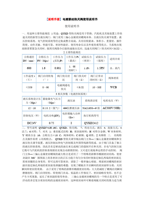
[说明手册]电液联动快关阀使用说明书使用说明书一.用途和主要性能规范1用途:QYKD型快关阀是用于管路、汽轮机及其他装置上作快速关闭的新型全液压阀门。
阀门采用三偏心金属密封蝶阀本体、全液压快关调节装置、液压控制系统、电气控制系统等经过集成整合而成,具有结构紧凑、体积小、重量轻、操作简便、动作灵敏、性能可靠、密封性能好、使用寿命长以及外观美观等优点。
当系统出现故障需要紧急关闭时,接到关阀指令后能快速做出反应,迅速关闭阀门(快关时间≤0.5S)。
法兰;6.对焊;7。
对夹1:垂直板式结构H:密封面材料:H 对焊合金钢、W本体材料、Y 硬质合金16:公称压力×10C:阀体材料:C碳钢、Q球铁、Z灰铸铁三.结构特点及操作原理1结构特点:QYKD型快关调节阀由阀门主体—三偏心金属密封蝶阀和全液压快关调节装置、液压控制站和电气控制箱及外围管线路等组成。
由于阀门具备了独立的液压控制系统,因此具有足够高的油压来完成阀门的强制开启和关闭。
在电气控制方面它既可与汽轮机组控制系统联结实现自动联锁控制,又可进行就地和远程的手动控制。
阀门主体—三偏心金属密封蝶阀的最大特点是采用了一个特殊的斜锥形椭圆密封结构,使密封副在360°圆周面上的各密封点的正压力趋于均匀分布同时使接近轴孔两端的密封面无需密封圈的自身变形,即可达到可靠密封,消除了一般单偏心球面、堆面密封蝶阀的密封副在接近轴孔两端的密封面易泄漏的难题,实现了蝶板在开启瞬间的密封面即分离,关闭瞬间即密封的效果。
由于采用了特殊的斜锥形椭圆密封结构,大大的减轻了蝶阀启闭瞬间磨擦扭矩,阀门启闭轻松,即使阀门在高、低温的工作情况下,密封面略有变形,也不会产生卡死现象,延长了密封副的使用寿命。
三偏心金属密封蝶阀的另一个特点是采用了可浮动的多层复合密封结构的金属密封座环,这种密封座环可顺着阀板关闭时的推力适当调整其自身的位置,补偿了机械传动机构在不同的工况下的运动轨迹的微小不重合对密封面的影响,消除了对密封面的损坏因素,延长了密封件的使用寿命,提高了金属密封蝶阀的密封效果和可靠性。
电液联动阀MPAC破管保护执行器操作说明书
Mpac 开关型电液执行器操作手册(中文版) Version 5.7 (03/08)目录:1概述 (1)1.1 引言 (1)1.2 维修周期 (1)1.3 需要的工具(仅仅指动力单元) (2)1.4 工作原理 (3)1.4.1 综述 (3)1.4.2执行器 (3)1.4.3 电控箱 (4)1.4.4 操作概述 (13)1.4.5 控制模式 (14)1.4.6 手动操作 (15)1.4.7 限位开关 (16)2 运输 (17)2.1 接收 (17)2.2 存储 (17)2.3 开箱 (17)3 油 (18)3.1 油位检查 (18)3.2 注油 (18)4 电控箱 (19)5 电气安装 (19)5.1 供电电源 (19)5.2 电缆 (19)5.2.1 电缆长度 (21)5.2.2 电缆走线 (21)5.3 挠性管及接头 (22)6. 执行器安装与调试 (23)6.1 安装前准备 (23)6.2 蓄能器充压 (23)6.3 安装 (23)6.4 开关极限位调整 (24)7 操作 (25)7.1 参数设置 (25)7.2 就地模式 (39)7.3 就地操作状态 (40)7.4就地状态下的阀门活动试验 (41)7.5 就地状态下的ESD (43)7.6 远控状态 (45)7.7远控状态下的活动试验 (46)7.8远控状态下的ESD (48)7.9 查询状态 (49)7.9.1 I/O状态查询 (49)7.9.2 参数查询 (50)7.9.3 指令历史查询 (51)7.9.4 故障解释 (52)7.9.5指令解释 (54)7.9.6 屏幕中的缩写 (54)安全注意事项电压冲击:执行器有可能产生电压冲击;只有有资质的安装和服务人员才能对设备进行安装和调整.对中:安装时执行器的轴孔和阀门的轴必须对中,若对中不良,将导致设备的损坏和人员的损伤。
避免突然启动:当安装执行器时确保切断电源;当执行器给电后,可能立即响应控制信号,这些不经意的动作可能对设备和人员造成损害。
电液高温闸阀说明书
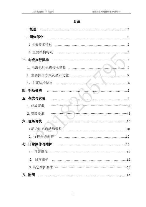
目录一.概述 (2)二.阀体部分 (2)1主要技术指标 (2)2 主要结构特点 (3)三. 电液执行机构 (4)1. 电液执行机构技术参数 (4)2. 主要操作方式及显示功能 (5)3、主要结构特点 (5)四. 手动机构 (7)五. 存放与安装 (8)1.存放要求 (8)2.安装要求 (8)六. 现场调校 (10)1.动力油站启动和调整 (10)2. 行程开关调整 (10)七. 日常操作与维护 (10)1. 日常操作 (10)2.日常维护 (12)3.其它维护要求 (13)八. 附图 (16)一、 概述电液大型烟机入口高温闸阀是烟气轮机--主风机组的配套控制阀门,是原电动和气动高温闸阀的更新换代产品。
它是烟气轮机的切断阀,安装在烟机入口水平管道上,正常操作时全开,事故时关闭,如(图一)所示,该阀由阀体部分、电液执行机构和手动机构组成。
该阀具有流通能力大、结构新颖、传动效率高、驱动力大、动作平稳可靠、使用寿命长、维护工作量少等特点。
二、 阀体部分1主要技术指标:根据装置工艺生产和烟气轮机--主风机组操作的具体要求,阀体规格与主要指标如下:型号规格LDY900 LDY1000 LDY1100 LDY1200设计压力 MPa(G) 0.3 0.3 0.3 0.3设计温度 ℃ 720 720 720 720 设计最大压差 MPa 0.3 0.3 0.3 0.3全开压降 kPa <2 <2 <2 <2阀门通径 mm 900 1000 1100 1200阀杆最大行程 mm 1050 1150 1250 13502 主要结构特点:阀体部分主要有阀体、阀盖、填料函体、阀座圈、导轨、阀板和阀杆等组成。
2.1 阀体阀体为大型厚壁高温合金钢板组焊结构,内部无衬里,与管道采用对焊连接。
阀体上设有导轨蒸气吹扫口,密封蒸气入口,阀体底部设有排凝口和紧急备用接口。
与阀盖采用方法兰连接,唇形密封。
2.2 阀盖、填料函体阀盖为高温合金钢板组焊结构,填料函体为碳钢组焊结构。
电液联动快关阀使用说明书
电液联动快关阀使用说明书使用说明书一.用途和主要性能规范1用途:QYKD型快关阀是用于管路、汽轮机及其他装置上作快速关闭的新型全液压阀门。
阀门采用三偏心金属密封蝶阀本体、全液压快关调节装置、液压控制系统、电气控制系统等经过集成整合而成,具有结构紧凑、体积小、重量轻、操作简便、动作灵敏、性能可靠、密封性能好、使用寿命长以及外观美观等优点。
当系统出现故障需要紧急关闭时,接到关阀指令后能快速做出反应,迅速关闭阀门(快关时间≤0.5S)。
法兰;6.对焊;7。
对夹1:垂直板式结构H:密封面材料:H 对焊合金钢、W本体材料、Y 硬质合金16:公称压力×10C:阀体材料:C碳钢、Q球铁、Z灰铸铁三.结构特点及操作原理1结构特点:QYKD型快关调节阀由阀门主体—三偏心金属密封蝶阀和全液压快关调节装置、液压控制站和电气控制箱及外围管线路等组成。
由于阀门具备了独立的液压控制系统,因此具有足够高的油压来完成阀门的强制开启和关闭。
在电气控制方面它既可与汽轮机组控制系统联结实现自动联锁控制,又可进行就地和远程的手动控制。
阀门主体—三偏心金属密封蝶阀的最大特点是采用了一个特殊的斜锥形椭圆密封结构,使密封副在360°圆周面上的各密封点的正压力趋于均匀分布同时使接近轴孔两端的密封面无需密封圈的自身变形,即可达到可靠密封,消除了一般单偏心球面、堆面密封蝶阀的密封副在接近轴孔两端的密封面易泄漏的难题,实现了蝶板在开启瞬间的密封面即分离,关闭瞬间即密封的效果。
由于采用了特殊的斜锥形椭圆密封结构,大大的减轻了蝶阀启闭瞬间磨擦扭矩,阀门启闭轻松,即使阀门在高、低温的工作情况下,密封面略有变形,也不会产生卡死现象,延长了密封副的使用寿命。
三偏心金属密封蝶阀的另一个特点是采用了可浮动的多层复合密封结构的金属密封座环,这种密封座环可顺着阀板关闭时的推力适当调整其自1身的位置,补偿了机械传动机构在不同的工况下的运动轨迹的微小不重合对密封面的影响,消除了对密封面的损坏因素,延长了密封件的使用寿命,提高了金属密封蝶阀的密封效果和可靠性。
电液联动快关阀使用说明书
[说明手册]电液联动快关阀使用说明书使用说明书一.用途和主要性能规范1用途:QYKD型快关阀是用于管路、汽轮机及其他装置上作快速关闭的新型全液压阀门。
阀门采用三偏心金属密封蝶阀本体、全液压快关调节装置、液压控制系统、电气控制系统等经过集成整合而成,具有结构紧凑、体积小、重量轻、操作简便、动作灵敏、性能可靠、密封性能好、使用寿命长以及外观美观等优点。
当系统出现故障需要紧急关闭时,接到关阀指令后能快速做出反应,迅速关闭阀门(快关时间≤0.5S)。
法兰;6.对焊;7。
对夹1:垂直板式结构H:密封面材料:H 对焊合金钢、W本体材料、Y 硬质合金16:公称压力×10C:阀体材料:C碳钢、Q球铁、Z灰铸铁三.结构特点及操作原理1结构特点:QYKD型快关调节阀由阀门主体—三偏心金属密封蝶阀和全液压快关调节装置、液压控制站和电气控制箱及外围管线路等组成。
由于阀门具备了独立的液压控制系统,因此具有足够高的油压来完成阀门的强制开启和关闭。
在电气控制方面它既可与汽轮机组控制系统联结实现自动联锁控制,又可进行就地和远程的手动控制。
阀门主体—三偏心金属密封蝶阀的最大特点是采用了一个特殊的斜锥形椭圆密封结构,使密封副在360°圆周面上的各密封点的正压力趋于均匀分布同时使接近轴孔两端的密封面无需密封圈的自身变形,即可达到可靠密封,消除了一般单偏心球面、堆面密封蝶阀的密封副在接近轴孔两端的密封面易泄漏的难题,实现了蝶板在开启瞬间的密封面即分离,关闭瞬间即密封的效果。
由于采用了特殊的斜锥形椭圆密封结构,大大的减轻了蝶阀启闭瞬间磨擦扭矩,阀门启闭轻松,即使阀门在高、低温的工作情况下,密封面略有变形,也不会产生卡死现象,延长了密封副的使用寿命。
三偏心金属密封蝶阀的另一个特点是采用了可浮动的多层复合密封结构的金属密封座环,这种密封座环可顺着阀板关闭时的推力适当调整其自身的位置,补偿了机械传动机构在不同的工况下的运动轨迹的微小不重合对密封面的影响,消除了对密封面的损坏因素,延长了密封件的使用寿命,提高了金属密封蝶阀的密封效果和可靠性。
电液动插板阀DYDCF600使用说明书14.4.8

石家庄科林威尔环保科技有限公司
二、产品简介
2.1 应用范围
该电液动插板阀属于控
制阀技术领域。用于建材、
冶金、矿山、电力、化工、
玻璃、轻工、粮食等行业的
库顶、库底及进出口等。
特别适用于各类无粘度
的固体、粉料及小于 Φ
120mm 的颗粒料,晶粒料
的输送及流量调节。是控制
流量变化较大,启动频繁,
切断迅速的理想设备。有很好的推广应用价值和广阔市场前景。
2.2 结构特点
本电液动插板阀结构简单、操作灵活、重量轻、无卡阻、切断快、不卡料、不成本低,使用性能好,生产效率高。安装
不受角度限制, 操作方便, 能随时调节开度等特点。该阀包括阀体、插板阀和控制装置。
该阀闸板采用优质碳素钢加工,再经过热处理工艺,闸板硬度高,不易变形,非常耐磨,使
四、电气控制 ........................................................................................................................................................... 8 4.1 指示灯及按钮简述..................................................................................................................................... 8 4.2 电路图........................................................................................................................................................ 9
电液阀说明书
电液阀电液阀是由电磁先导阀控制膜片运动的液动阀。
电液阀能手动控制和自动控制,由控制器控制,能进行自动调节,实现恒流功能;能多段开、闭阀门,消除水击现象,特别适用于石油化工等行业,以实现对输送介质流量的自动控制。
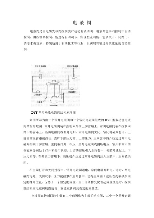
DYF型多功能电液阀结构原理图如图所示为由一个常开电磁阀和一个常闭电磁阀组成的DYF型多功能电液阀结构原理图。
常开电磁阀装在控制回路的上游管路上,常闭电磁阀装在控制回路下游管路上,当两电磁阀线圈通电后,常开电磁阀关闭,常闭电磁阀打开,上游的高压管路被挡住,膜片下部压力高于上部压力,主阀套中的介质通过常闭电磁阀排到下游管路,主阀被打开。
相反,当两电磁阀线圈断电后,常开和常闭的电磁阀分别处于打开和关闭状态,上游的高压引入主阀套中,使膜片通过上、下压力相等,在弹簧力作用下,高压端介质通过常开电磁阀注入主膜中,主阀被关闭。
在主阀打开和关闭过程中,常开电磁阀通电,常闭电磁阀断电。
这时,两电磁阀均处于关闭状态,压力被藏聚在主阀套中,使得主阀由于液压差而被锁在固定的打开位置,保持了一个恒定的流量。
当工作条件变化引起流量变化时,控制器给相应电磁阀线圈通电,就能重新调到设定的流量值。
电液阀在控制回路中装有二个球阀作为主阀的响应阀,其中一个是开启调节阀,另一个是关闭调节阀。
使用过程中,可根据介质粘度和压力,调整两球阀的开启度就能微调主阀的启闭时间,以达到消除水击的目的。
多功能电液阀的功能特点:(1)可多段开、闭,消除水击。
对于一个一般的发油系统,水击的冲击压力往往超过管路上相关设备的最高限压,有时甚至达3倍以上。
这就足以使管路上的泵、阀、流量计、压力计、过滤器等设备遭到不同程度的破坏,导致寿命缩短,动作出错,严重时使作业瘫痪。
DYF型多功能电液阀是消除水击的理想阀门,它的启、闭时间连续可调(从2s到无限长)。
根据实际使用得知:一般情况下,开阀时间调到2s左右,关阀时间调到4s~5s即可基本消除水击现象。
(2)可控调节,实现恒流。
CSDY1射流管电液伺服阀产品说明书

精心整理CSDY1射流管电液伺服阀产品说明书编制:校对:审核:一、CSDY1二、图1是被夹牢在阀芯的中心位置。
高压油连续地从供油腔Ps通过滤油器及固定节流孔,到射流管喷嘴向两个接受孔喷射,接受孔分别与阀芯两端控制腔相通。
当力矩马达线圈组件输入控制电流时,由于控制磁通和极化磁通的相互作用,在衔铁上产生一个力矩,该力矩使衔铁组件绕弹簧管旋转,从而使射流管喷嘴运动导致两个接受孔腔产生压差引起阀芯位移,且一直持续到由反馈弹簧组件弯曲产生的反馈力矩与控制电流产生的控制力矩相平衡为止。
由于阀芯位移与反馈力矩成比例,控制力矩与控制电流成比例,伺服阀的输出流量与阀芯位移成比例,所以伺服阀的输出流量与输入的指令控制电信号亦成比例,若给伺服阀输入反向电控信号,则伺服阀就有反向流量输出。
三、1234≤5567891011≥40(用于低频控制系列)12、相频宽(-90°)(HZ)≥90四、线圈连接方法:伺服阀线圈的连接方法,插销头标号,外引出线颜色及控制电流的极性等参照下表和射流管电液伺服阀安装图(图2)1、冲洗板1件2、伺服阀接口处o型圈10.2×1.94件3、插头CX2—4M1件4、滤油器组件(含密封圈)1件五、概述:CSDY1系列射流管电液伺服阀是力反馈型两级流量伺服控制阀,具有性能良好,抗污染能力强,安全可靠以及寿命长的突出特点,适用于电液伺服系统的位置、速度、加速度和力的控制。
六、结构原理:图1是CSDY1系列射流管电液伺服阀的原理图,力矩马达采用永磁力矩马达,由两个永七、1、供油压力范围(MPa)2.1~31.52、额定供油压力(MPa)20.63、额定流量(L/min)2—40(按用户要求)4、滞环(%)≤3≤5(用于低频控制系统)5、分辨率(%)≤0.256、线性度(%)≤7.57、对称度(%)≤108、压力增益(%Ps/1%In)≥309、静耗流量(L/min)≤0.45+3%Qn八、注意事项:1、伺服阀安装前应先装上随带附件:冲洗板。
威尔克森电子漏水阀说明书
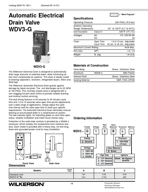
SpecificationsOperating Pressure 230 PSIG (15,9 bar)Ambient Operating Range Temperature 33° to 130°F (0,1° to 54°C)Coil Insulation Class H 340°F (171,1°C)Voltages AC 115, 230/50-60DC24Timer Open Time 1/2 to 10 sec., AdjustableCycle Time 30 sec. to 45 min., AdjustableMaximum Current Rating4mA Max.Port Size NPT 1/4, 1/2Weightlb. (kg)1.8 (0,8)Materials of ConstructionValve Body Brass / Stainless SteelEnclosure NEMA 4 ABS PlasticInternal Parts Brass / Stainless SteelSealing MaterialNBR, FKM, EPDMAutomatic Electrical Drain Valve WDV3-GWDV3-GFront ViewSide ViewPipe ValveFamilyVoltageSizeMaterial Pressure OptionsOrdering InformationThe Wilkerson Electrical Drain is designed to automatically drain large amounts of collected water, while minimizing air loss from compressed air systems. This drain is ideally suited to draining separators, receivers, refrigerated dryers, filters and drop legs.The Wilkerson Automatic Electrical Drain guards againstdamage by liquid carryover. The unit discharges up to 20 GPM at 100 PSIG. This normally closed valve is designed with a non-clogging full-port drain orifice to provide reliable draining and minimal routine servicing.The dual timing features of 30 seconds to 45 minutes cycle time and 1/2 to 10 seconds valve open time permit adjustments over a wide range of applications. Simply adjust the cycle time interval and the valve open time to meet your specificrequirements. The Automatic Electrical Drain eliminates manual draining of accumulated water in a compressed air system. The two indicator lights, for indicating power on and valve open status, simplify installation and make visual checks easy. Protection of the solid state controls is provided by a NEMA 4 enclosure, which isolates the components from moisture and dust. Each model is provided with a heavy-duty, six-foot-long, three-wire grounded power cord for easy installation.Dimensions(Revised 05-14-07)16Catalog 9EM-TK-190-1Pneumatic Division Richland, Michigan。
VT-2000BS40 G型电液比例控制阀说明书

VT-2000BS40 G型电液比例控制阀说明书
VT-2000BS40 G型电液比例控制器用于VA/E变量叶片泵,A7V、A2V轴向柱塞泵,A6V轴向柱塞马达及DBE系列先导式比例溢流阀,DBE系列先导式比例压力阀的控制。
一、主要技术参数
1.电源:直流24V(22V-35V)
2.功率:30w
3.负载电阻:18-25Ω
4.先导电流:100mA
5.颤振频率:200/100Hz
6.最大输出电流:800mA
7.控制电压:±9v±1%
8.环境温度:0-40℃(军品环境温度-40-+60℃)
9.温度漂移:0.5(最大电流值的)‰℃
注:1.产品出厂时已按上述技术参数调定,用户如有特殊技术要求请在订货时提出。
2.本公司可为用户提供军品级产品。
二、使用方法:
VT-2000BS40 G型电液比例控制器的原理方框图
按下列顺序接线:
1.虚线右侧20a(或20c),22a(22c)端接比例电磁铁线圈,两点可以互换。
22a(或22c)是高电位端,20a(或20c)是低电位端。
2.虚线左侧24a(或24c)和18a(18c、16a、16c)接直流24v电源,其中24a (24c)接电源正极,18a(18c、16a、16c)接电源负极。
本控制器要求独立电源供电,不能与其它24v电器元件公用电源,否则将有可能烧坏R48.
3.控制器有两种控制方式:(1)手动控制:a:外设电位器(用户自备,建议使用阻值大于5K小于10k,但不得小于2k;功。
电液控制阀说明书
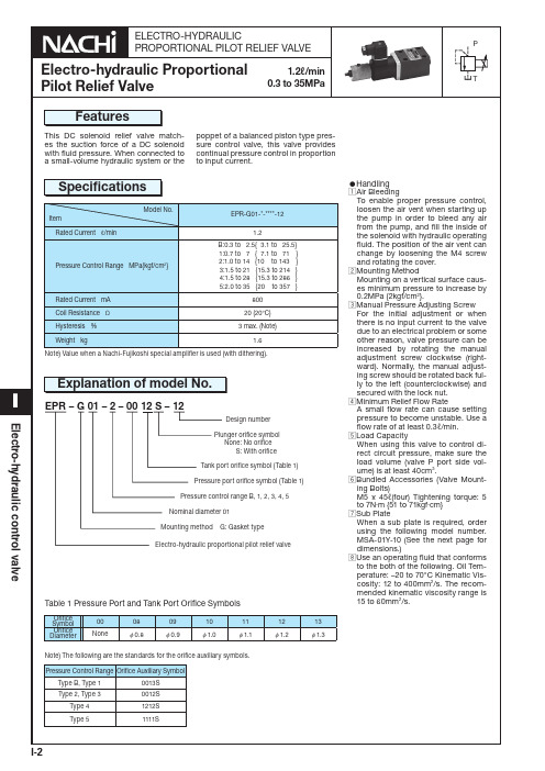
Orifice Symbol Orifice Diameter
00 None
08 φ 0.8
09 φ 0.9
10 φ 1.0
11 φ 1.1
12 φ 1.2
13 φ 1.3
•Handling zAir Bleeding
To enable proper pressure control, loosen the air vent when starting up the pump in order to bleed any air from the pump, and fill the inside of the solenoid with hydraulic operating fluid. The position of the air vent can change by loosening the M4 screw and rotating the cover. xMounting Method Mounting on a vertical surface causes minimum pressure to increase by 0.2MPa {2kgf/cm2}. cManual Pressure Adjusting Screw For the initial adjustment or when there is no input current to the valve due to an electrical problem or some other reason, valve pressure can be increased by rotating the manual adjustment screw clockwise (rightward). Normally, the manual adjusting screw should be rotated back fully to the left (counterclockwise) and secured with the lock nut. vMinimum Relief Flow Rate A small flow rate can cause setting pressure to become unstable. Use a flow rate of at least 0.3ℓ/min. bLoad Capacity When using this valve to control direct circuit pressure, make sure the load volume (valve P port side volume) is at least 40cm3. nBundled Accessories (Valve Mounting Bolts) M5 x 45ℓ(four) Tightening torque: 5 to 7N·m {51 to 71kgf·cm} mSub Plate When a sub plate is required, order using the following model number. MSA-01Y-10 (See the next page for dimensions.) ,Use an operating fluid that conforms to the both of the following. Oil Temperature: –20 to 70°C Kinematic Viscosity: 12 to 400mm2/s. The recommended kinematic viscosity range is 15 to 60mm2/s.
阀门遥控系统(电液式)

阀门遥控装置说明书
Drawing No.:2511-330-10-01
3.2 接线箱 数量为:2 个 外壳防护等级:IP44; 安装方式:挂壁式。 电缆进口:底部
4. 工作原理 本系统的主电源由船厂提供双相 AC380V/50Hz 电源,在主机舱的压载控制台上通过操作旋钮
来发出开关信号通过接线箱控制电液泵电机转向,以液压油来改变驱动头中活塞运动方向,从而 实现对各个舱室中的阀门的开、关及开启程度控制。
5.4.7. 支承件之间的距离一般应按表 1 的要求选择。
表 1 电缆外径与支承件距离(mm)
电缆外径
支承件距离
超过 — 8 13 20 30
不超过 8 13 20 30 —
非铠装电缆 200 250 300 350 400
铠装电缆 250 300 350 400 450
5.4.8. 电缆在金属管子、管道、电缆槽内敷设时,应符合下列规定: ⑴金属管子或管道或电缆槽内壁应光滑,并应有防蚀措施; ⑵金属管子或管道或电缆槽的端部应采取措施以使电缆的护套或外护层不致受损; ⑶管子或管道的内截面积和弯曲半径,应使其中的电缆容易拉进和拉出,管子或管道的弯由
阀门遥控装置说明书
Drawing No.:2511-330-10-01
图 4 阀门遥控系统的电源、信号和控制线的连接示意图
5.4.2. 连接电缆(线)的规格应符合接线图的规定,应优先选用经各国船级社认可的型号。
5.4.3. 电缆的走线应尽可能平直、避免潮气或水滴凝结的影响且易于检修。
5.4.4. 电缆的走线应尽量远离锅炉、热管、电阻器等的热源,并具有不受机械损伤的保护。用
1# 接线箱 No.1 COLLECTION CABINET
2# 接线箱 No.2 COLLECTION CABINET
电液控蝶阀、电动蝶阀规范书

电动蝶阀技术规范书目录一、设备名称、规格型号、数量、单位 (3)二、供货范围 (3)1 一般要求 (3)2 供货范围 (3)三、参考标准 (5)四、技术要求及技术条件 (5)1 技术要求 (5)2 设备规范 (11)3 设计界限 (12)4 包装和运输 (12)五、监造、检验和性能验收试验 (13)1 概述 (13)2 工厂检验 (14)3 设备监造 (14)4 性能验收试验 (16)六、技术资料、图纸提供要求 (17)1 一般要求 (17)2 资料提交的基本要求 (17)七、安装方式 (19)八、质保要求及技术服务要求 (19)1设备质量保证 (19)2 性能保证值 (20)3 投标方现场技术服务 (20)4 培训 (21)九、设备交货时间及交货批次要求 (22)十、技术差异表 (22)十一、其它 (22)一、设备名称、规格型号、数量、单位设备名称:电动蝶阀(蝶阀的阀芯采用三偏心结构)规格型号:D943H-10C公称直径:DN3000mm数量:台二、供货范围1 一般要求1.1本技术规范书规定了合同设备的供货范围。
投标方保证提供设备为全新的、先进的、成熟的、完整的和安全可靠的,且设备的技术经济性能符合技术规范书的要求。
1.2投标方提供详细供货清单,清单中依次说明型号、数量、产地、生产厂家等内容。
对于属于整套设备运行和施工所必需的部件,如果本合同附件未列出和/或数量不足,投标方仍需在执行合同时补足。
1.3除有特别注明外,所列数量均为4台机组所需。
1.4投标方提供所有安装和检修所需专用工具和部件等,并提供详细供货清单。
1.5提供所供设备中的进口件清单,并要求提供相关设备原产地证明及进口报关手续。
1.6如有外购件,投标方必须提供三家生产厂家供招标方选择。
2 供货范围投标方应确保供货范围完整,以能满足招标方安装、运行要求为原则,在技术规范中涉及的供货要求也作为本供货范围的补充,若在安装、调试、运行中发现缺项(属投标方供货范围)由投标方补充。
智能基础设施电液阀值电机4561说明书
4561Electrohydraulic actuators for valveswith a 20 mm stroke SKD32.. SKD82.. SKD62.. SKD60..•SKD32.. Operating voltage AC 230 V, 3-position control signal•SKD82.. Operating voltage AC 24 V, 3-position control signal•SKD6.. Operating voltage AC 24 V, control signal DC 0…10 V, 4…20 mA or0...1000 Ω•SKD6.. Choice of flow characteristic, position feedback, stroke calibration,LED status indication, override control•SKD62UA w ith functions choice of direction of operation, stroke limit control,sequence control with adjustable start point and operating range,operation of frost protection monitors QAF21.. and QAF61..•Positioning force 1000 N•Actuator versions with or without spring-return function•For direct mounting on valves; no adjustments required•Manual adjuster and position indicator•Optional functions with auxiliary switches, potentiometer, stem heater andmechanical stroke inverter•SKD..U are UL-approvedCM1N4561en2/20UseFor the operation of Siemens 2-port and 3-port valves, types VVF.., VVG.., VXF.. and VXG.. with a 20 mm stroke as control and safety shut-off valves in heating, ventilation and air conditioning systems.Types1) Approbation: CE 3)Direction of operation, stroke limit control, sequence control, signal addition2)Approbation: CE, ULWhen ordering please specify the quantity, product name and type code. Example: 1 actuator, type SKD32.50 and 1 potentiometer, type ASZ7.3 and 1 dual auxiliary switches ASC9.3The actuator, valve and accessories are supplied in separate packaging and not assembled prior to delivery.See overview, section «Replacement parts», page 19.AccessoriesOrderingDeliverySpare parts3/20Equipment combinationsFor admissible differential pressures ∆p max and closing pressures ∆p s , refer to the relevant valve data sheets. 1)Valves are phased-outThird-party valves with str okes between 6…20 mm can be motorized, provided they are «closed with the de-energized» fail-safe mechanism and provided that the necessary mechanical coupling is available. For SKD32.. and SKD82.. the Y1 signal must be routed via an additional freely-adjustable end switch (ASC9.3) to limit the stroke.We recommend that you contact your local Siemens office for the necessary information.Overview table, see page 20.Technology1 Manual adjuster2 Pressure cylinder3 Suction chamber4 Return spring5 Solenoid valve6 Hydraulic pump7 Piston8 Pressure chamber 9 Position indicator (0 to 1) 10 Coupling 11 Valve stem 12 Plug Valve closed Valve openNoteRev. no. Principle ofelectro-hydraulic actuators4/20The hydraulic pump (6) forces oil from the suction chamber (3) to the pressure chamber (8) and thereby moving the pressure cylinder (2) downwards. The valve stem (11) retracts and the valve opens. Simultaneously the return spring (4) is compressed. Activating the solenoid valve (5) allows the oil in the pressure chamber to flow back into the suction chamber. The compressed return spring moves the pressure cylinder upwards. The valve stem extends and the valve closesTurning the manual adjuster (1) clockwise moves the pressure cylinder downwards and opens the valve. Simultaneously the return spring is compressed.In the manual operation mode the control signals Y and Z can further open the valve but cannot move to the «0%» stroke position of the valve. To retain the manually set position, switch off the power supply or disconnect the control signals Y and Z. The red indicator marked «MAN» is visible.When setting the controller for a longer time period to manual operation, werecommend adjusting the actuator with the manual adjuster to the desired position. This guarantees that the actuator remains in this position for that time period. Attention: Do not forget to switch back to automatic operation after the controller is set back to automatic control.Turn the manual adjuster counterclockwise to the end stop. The pressure cylinder moves upward to the «0%» stroke position of the valve. The red indicator marked «MAN» is no longer visible.The actuator can manually be adjusted to a stroke position > 0 % allowing its use in applications requiring constantly a minimal volumetric flow.The SKD32.51, SKD32.21, SKD82.51.. and SKD62.. actuators, which feature a spring-return function, incorporate a solenoid valve which opens if the control signal or power fails. The return spring causes the actuator to move to the «0 %» stroke position and closes the valve.The actuator is controlled by a 3-position signal either via terminals Y1 or Y2 and generates the desired stroke by means of above described principle of operation. • Voltage on Y1 piston extends valve opens • Voltage on Y2 piston retracts valve closes • No voltage on Y1 and Y2 piston / valve stem remain in the respective positionThe valve is either controlled via terminal Y or override control Z. The positioning signal Y generates the desired stroke by means of above described principle of operation. • Signal Y increasing: piston extends valve opens • Signal Y decreasing: piston retracts valve closes • Signal Y constant: piston / valve stem remain in the respective position • Override control Z see description of override control input, page 8A frost protection thermostat can be connected to the SKD6.. actuator. The added signals from the QAF21.. and QAF61.. require the use of SKD62UA actuators. Notes on special programming of the electronics are described under «Enhanced electronics» on page 5.«Connection diagrams» for operation with frost protection thermostat or frost protection monitor refer to page 16.Opening the valveClosing the valveManual operation modeNote: Controller in manual operationAutomatic modeMinimal volumetric flow Spring-return facilitySKD32../SKD82..3-position control signalSKD62.., SKD60.. Y control signal DC 0...10 V and/orDC 4...20 mA, 0…1000 ΩFrost protection monitorFrost protectionthermostat5/201 Connection terminals2 Mode DIL switches3 LED status indication4 Slot for calibration0163811Connection terminals 2 DIL switches 3 LED status indication4 Stroke calibration 5Rotary switch Up (factory setting 0) 6Rotary switch Lo420 mAStandard electronics SKD62.., SKD60..DIL switches SKD62.., SKD60..Enhanced electronics SKD62UADIL switches SKD62UA6/20• With normally-closed valves, «direct-acting» means that with a signal input of 0 V, the valve closes (applies to all Siemens valves listed under «equipment combinations» on page 3)• With normally-open valves, «direct-acting» means that with a signal input of 0 V, the valve is open.100 %0 %4 mA 0 Ω20 mA 1000 ΩThe mechanical spring-return function is not affected by the direction of operation selected.Selection of direction of operation SKD62UANote7/20Prerequisites• • Actuator must be in «Automatic operation» enabling stroke calibration to capture the effective 0 % and 100 % values • AC 24 V power supply • Housing cover removed Calibration1. Short-circuit contacts in calibration slot (e.g. with a screwdriver)2. Actuator moves to «0 %» stroke position (1) (valve closed)3. Actuator moves to «100 %» stroke position (2) (valve open)4.Measured values are storedgreen LED flashes; position feedback U inactiveA lit red LED indicates a calibration error.The calibration can be repeated any number of times.Stroke limit control and sequence control SKD62UAStroke control withQAF21.. / QAF61.. signal addition SKD62UA onlyCalibrationSKD62.., SKD60..8/20The LED status indication indicates operational status with dual-colored LED and is visible with removed cover.LED Indication FunctionRemarks, troubleshootingGreen LitNormal operationAutomatic operation; everything o.k.FlashingCalibration in progressWait until calibration is finished (LED stops flashing, green or red LED will be lit) RedLitFaulty stroke calibration Check mountingRestart stroke calibration (by short-circuiting calibration slot)Internal errorReplace electronics FlashingInner valve jammed Check valveBothDarkNo power supply Electronics faultyCheck mains network, check wiring Replace electronicsAs a general rule, the LED can assume only the states shown above (continuously red or green, flashing red or green, or off).Override control input can be operated in following different modes of operationZ-modeno functionfully openclosedoverride with 0…1000 ΩSignal addition SKD62UA onlyC o n n e c t i o n sT r a n s f e r linear or equal-percentagelinear or equal-percentagelinear or equal-percentage• Z-contact not connected • Valve stroke follows Y-input• Z-contact connected directly to G • Y-input has no effect • Z-contact connected directly to G0 • Y-input has no effect • Z-contact connected to M via resistor R • Starting position at50 Ω / end position at 900 Ω• Y-input has no effect • Z-contact is connected to R ofthe frost protection monitor QAF21.. or QAF61.. • Valve stroke followssignals Y and R(Z)Shown operation modes are based on the factory setting «direct acting» Y-input has no effect in Z-mode.Indication of operating state SKD62.., SKD60..Override control input ZSKD62.., SKD60..Note9/20Accessories ASZ6.6 (S55845-Z108) stem heater• for media below 0 °C• mount between valve and actuatorASC9.3double auxiliary switchASZ7.3potentiometerASK50stroke inverter4561Z 05005154561Z 10adjustable switching points0…1000 Ω0 % actuator stroke corresponds to 100 % valve stroke; mount between valve and actuatorFor the combination SIMATIC S5/S7 and position feedback message, we recommend actuators with DC 0…9.8 V feedback signals.The signal peaks that occur in the potentiometer ASZ7.3 may result in error messages on Siemens SIMATIC.This is not the case when combined with Siemens HVAC controllers.The reason is that SIMATIC has a higher resolution and faster response time.ASC1.6auxiliary switchswitching point 0…5 % strokeSee section «Technical data» on page 13 for more information.SKD..SKD32.., SKD82..Note: ASZ7.3SKD62.., SKD60..10/20Engineering notesConduct the electrical connections in accordance with local regulations on electrical installations as well as the internal or connection diagrams.Safety regulations and restrictions designed to ensure the safety of people and property must be observed at all times!The plant operator must also ensure compliance with applicable guidelines on cable insulation when using a safety limiter. Failure to comply may cause the safety limiter function to fail.For media below 0 °C the ASZ6.6 stem heater is required to keep the valve from freezing. For safety reasons the stem heater is designed for an operating voltage of AC 24 V / 30 W.For this case, do not insulate the actuator bracket and the valve stem, as air circulation must be ensured. Do not touch the hot parts without prior protective measures to avoid burns.Non-observance of the above may result in accidentsand fires!Recommendation: Above 140 °C insulating the valves is strictly recommended.Observe admissible temperatures, refer to «Use» on page 2 and «Technical data» on page 13.If an auxiliary switch is required, its switching point should be indicated on the plant schematic.Every actuator must be driven by a dedicated controller (refer to«Connection diagrams», page 16).11/20Mounting instructionsMounting Instruction 74 319 0325 0 for fitting the actuator to the valve are by packed in the actuator packaging. The instructions for accessories are enclosed with the accessories themselves.Commissioning notesWhen commissioning the system, check the wiring and functions, and set any auxiliary switches and potentiometers as necessary, or check the existing settings. Coupling fully retracted→stroke = 0%Coupling fully extended→ stroke = 100 %The manual adjuster must be rotated counterclockwise to the end stop, i.e. until the red indicator marked «MAN» is no longer visible. This causes the Siemens valves, types VVF.., VVG.., VXF.. and VXG.. to close (stroke = 0%).Manual operation «M A N»Automatic operation« A U T O »Orientation12/20Maintenance notesThe SKD.. actuators are maintenance-free.When servicing the actuator:• Switch off pump of the hydronic loop• Interrupt the power supply to the actuator • Close the main shutoff valves in the system• Release pressure in the pipes and allow them to cool down completely • If necessary, disconnect electrical connections from the terminals• The actuator must be correctly fitted to the valve before recommissioning. Recommendation SKD6..: trigger stroke calibration.«Replacement parts», see page 19.A damaged housing or cover represents an injury risk• NEVER uninstall an actuator from the valve• Uninstall the valve-actuator combination (actuating device) as a complete device• Use only properly trained technicians to uninstall the unit• Send the actuating device together with an error report to your local Siemens representative for analysis and disposal• Properly mount the new actuating device (valve and actuator)Parts could fly ultimately resulting in injuries from uninstalling an actuator with a damaged valve housing due to the tensioned return spring.DisposalWarrantyTechnical data on specific applications are valid only together with Siemens products listed under "Equipment combinations", page 3. Siemens rejects any and all warranties in the event that third-party products are used.RepairTechnical dataPower supplySignal inputsPositionfeedbackElectricalconnectionsStandards,directives andapprovals13/2014/20Environmental compatibilityDimensions / weightMaterialsThe documents can be downloaded from /bt/download .Accessories ASC1.6 ASC9.3 double ASZ7.3 Potentiometer ASZ6.6 stem heaterSKD62UA enhanced functionsDirection of operationDirect-acting, reverse-actingDC 0...10 V / DC 10...0 V DC 4...20 mA / DC 20...4 mA 0...1000 Ω / 1000...0 Ω Stroke limit control Range of lower limit Range of upper limit 0...45 % adjustable 100...55 % adjustable Sequence controlTerminal YStarting point of sequence Operating range of sequence0...15 V adjustable 3...15 V adjustable Signal additionZ connected to R ofFrost protection monitor QAF21.. Frost protection monitor QAF61..0...1000 Ω, added to Y signal DC 1.6 V, added to Y signalAmbient conditions and protection dataClassification to IEC/EN 60730 Automatic action: Type 1AA / Type 1AC / Modulation Action Pollution degree: 2Housing protection as perIEC/EN 60529IP54 Environmental conditionsTransportation(in transport packaging) to IEC/EN 60721-3-2 Class 2K3Temperature -30...65 °CHumidity 5...95 % (no condensation)Operationto IEC/EN 60721-3-3 Class 3K5Temperature -15...50 °CHumidity 5...95 % (no condensation)Storageto IEC/EN 60721-3-1 Class 1K3Temperature -15...50 °CHumidity 5...95 % (no condensation)Internal diagramsSKD32.51, SKD32.21 AC 230 V, 3-PositionCm1end switchn solenoid valve for spring-returnc1, c2ASC9.3 double auxiliaryswitcha, b, c ASZ7.3 potentiometerY1Positioning signal «open»Y2Positioning signal «close» 21spring-return functionN neutral conductorSKD32.50AC 230 V, 3-PositionY2Positioning signal «close»21spring-return functionG System potentialSKD82.50AC 24 V, 3-PositionSKD60, SKD60U,SKD62,SKD62U, SKD62UAAC 24 V, DC 0…10 V,4…20 mA, 0…1000 ΩU position indicationZ override controlY positioning signalM measuring neutralG0operating voltage AC 24 V:system neutral (SN)G operating voltage AC 24 V:system potential (SP)Switching without power asa spring return function15/2016/20Connection terminals U ZG 0G Y M operating voltage AC 24 V: system neutral (SN) operating voltage AC 24 V: system potential (SP)Positioning signal DC 0...10 (30) V or DC 4...20 mA Measuring neutral (= G0)Position indication DC 0...10 V or DC 4...20 mAOverride control (functionality see page 8)Connection diagrams SKD32.21, SKD32.51SKD32.50F1 safety limiter (eg.temperature limiter) N1, N2 controller Y1, Y2actuatorsL Phase N neutralY1 Positioning signal «open» Y2 Positioning signal «close» 21Spring-return functionSKD6..Auxiliary switch ASC1.6SKD32.. AC 230 V 3-Position17/20SKD82.51, SKD82.51USKD82.50, SKD82.50USNSPSNSPSNSPSPAC 24 VF1 safety limiter (eg temperature limiter) N1, N2 controller Y1, Y2 actuators SP Systempotential AC 24 V SN System neutral (Y1), (Y2) controller contactsY1 Positioning signal «open» Y2 Positioning signal «close» 21 Spring-return functionSKD60SKD60USKD82.. AC 24 V 3-PositionSKD6..AC 24 VDC 0…10 V, 4…20 mA, 0…1000 Ω18/20SKD62 SKD62U SKD62UAY1 actuator N1 controllerF1 safety limiter (eg temperature limiter) F2frost protection thermostatterminals: 1 – 2 frost hazard / sensor is interrupted (thermostat closes with frost) 1 – 3 normal operation F3 Temperature detector F4 Frost protection monitor with 0…1000 Ω signal output, e.g. QAF21.. or QAF61.. (only SKC62UA) * G (SP) System potential AC 24 V G0 (SN) System neutral* Only with sequence control and the appropriate selector switch settings (see page 5ff)When using the safety limiter F1, ensure that no mistakes may occur on cableinsulation that may cancel out the temperature limiter function (applies to both 230 V as well as 24 V types).For SN earthing (e.g. PELV) comply under all circumstances with the note above.19/20DimensionsAll dimensions in mm*Height of actuator from valve plate without stroke inverter ASK50 = 300 mm Height of actuator from plate with stroke inverter ASK50 = 357 mm** SKD..U with knockouts for standard ½" conduit connectors (Ø 21.5 mm) ► = >100 mm ⎧ Minimum clearance from ceiling or wall for mounting, ►► = >200 mm ⎩ connection, operation, maintenance etc.20*109,535444456,5108181,580∅∅4561M 02* Maximum stroke = 20 mmReplacement partsOrder numbers for replacement partsCoverHand control 1)Control unitActuator typeSKD32.50 410456348 426855048 SKD32.51 410456348 426855048 SKD32.21 410456348 426855048 SKD82.50 410456348 426855048 SKD82.50U 410456348 426855048 SKD82.51 410456348 426855048 SKD82.51U 410456348 426855048SKD62 410456348 426855048 466857488 SKD62U 410456348 426855048 466857488 SKD60 410456348 426855048 466857598 SKD60U 410456348 426855048 466857598 SKD62UA4104563484268550484668575181)hand control, blue with mechanical partsASK50 stroke inverterRevision numbersPublished by:Siemens Switzerland Ltd. Building Technologies Division International Headquarters Gubelstrasse 226301 ZugSwitzerlandTel. +41 58-724 24 24/buildingtechnologies© Siemens Switzerland Ltd 1998 Delivery and technical specifications subject to change20/20。
- 1、下载文档前请自行甄别文档内容的完整性,平台不提供额外的编辑、内容补充、找答案等附加服务。
- 2、"仅部分预览"的文档,不可在线预览部分如存在完整性等问题,可反馈申请退款(可完整预览的文档不适用该条件!)。
- 3、如文档侵犯您的权益,请联系客服反馈,我们会尽快为您处理(人工客服工作时间:9:00-18:30)。
电液阀
电液阀是由电磁先导阀控制膜片运动的液动阀。
电液阀能手动控制和自动控制,由控制器控制,能进行自动调节,实现恒流功能;能多段开、闭阀门,消除水击现象,特别适用于石油化工等行业,以实现对输送介质流量的自动控制。
DYF型多功能电液阀结构原理图
如图所示为由一个常开电磁阀和一个常闭电磁阀组成的DYF型多功能电液阀结构原理图。
常开电磁阀装在控制回路的上游管路上,常闭电磁阀装在控制回路下游管路上,当两电磁阀线圈通电后,常开电磁阀关闭,常闭电磁阀打开,上游的高压管路被挡住,膜片下部压力高于上部压力,主阀套中的介质通过常闭电磁阀排到下游管路,主阀被打开。
相反,当两电磁阀线圈断电后,常开和常闭的电磁阀分别处于打开和关闭状态,上游的高压引入主阀套中,使膜片通过上、下压力相等,在弹簧力作用下,高压端介质通过常开电磁阀注入主膜中,主阀被关闭。
在主阀打开和关闭过程中,常开电磁阀通电,常闭电磁阀断电。
这时,两电磁阀均处于关闭状态,压力被藏聚在主阀套中,使得主阀由于液压差而被锁在固定的打开位置,保持了一个恒定的流量。
当工作条件变化引起流量变化时,控制器给相应电磁阀线圈通电,就能重新调到设定的流量值。
电液阀在控制回路中装有二个球阀作为主阀的响应阀,其中一个是开启调
节阀,另一个是关闭调节阀。
使用过程中,可根据介质粘度和压力,调整两球阀的开启度就能微调主阀的启闭时间,以达到消除水击的目的。
多功能电液阀的功能特点:
(1)可多段开、闭,消除水击。
对于一个一般的发油系统,水击的冲击压力往往超过管路上相关设备的最高限压,有时甚至达3倍以上。
这就足以使管路上的泵、阀、流量计、压力计、过滤器等设备遭到不同程度的破坏,导致寿命缩短,动作出错,严重时使作业瘫痪。
DYF型多功能电液阀是消除水击的理想阀门,它的启、闭时间连续可调(从2s到无限长)。
根据实际使用得知:一般情况下,开阀时间调到2s左右,关阀时间调到4s~5s即可基本消除水击现象。
(2)可控调节,实现恒流。
由控制器控制常开和常闭两个电磁阀通、断电,可以使电液阀的开度任意调节,从而使其输出的流量按需变化。
如果需恒定流量,只要流量信号反馈给控制器,控制器就能通过调节两电磁阀,使用权输出流量保持恒定。
(3)利用介质压力,开启压力小。
(4)使用寿命长。
(5)控制回路简单,维修方便。
(6)无填料密封,密封可靠。
(7)可水平、垂直安装,适用范围广。