MV_verification
IC_verification基本知识点
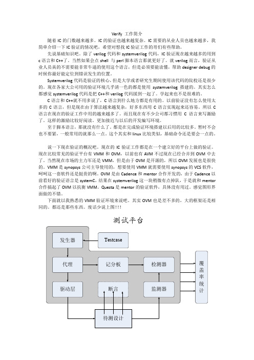
Verify 工作简介随着IC的门数越来越多。
IC的验证也越来越复杂。
IC需要的从业人员也越来越多,我简单介绍一下IC验证的情况吧,希望对想找IC验证工作的哥们有些帮助。
先说基础知识吧。
除了verilog代码和systemverilog代码,IC验证现在越来越多的用到c语言和C++了。
当然如果会点shell 与perl脚本语言那就更好了。
就verilog而言,验证从业人员真的不需要能非常牛逼的使用这个语言,但是必须要能读懂,帮助designer debug的时候你最好能定位到错误发生的位置。
Systemverilog代码是验证的核心,但是大学或者研究生期间使用该代码的院校还是很少的。
现在各家大公司用的验证环境几乎清一色的都是使用systemverilog搭建的。
其实怎么都感觉systemverilog代码是把C++和verilog代码揉到一起了。
学起来也不是很难的。
C语言和C++就不用多说了,C语言到什么地方都是有用的。
以前验证没有怎么使用太多的C语言,但是现在由于算法越来越复杂,好多东西用C语言实现起来还容易。
所以C 语言在现在的验证工作中用的越来越多了。
而且现在有不少公司都习惯用C语言来写激励了。
这样的激励比较好阅读。
更加接近与以后的开发编写环境。
至于脚本语言,那就没有什么了。
都是在完成验证环境搭建以后用的比较多。
暂时不会也不要紧,一般常用的就那么一点。
这个其实和linux比较类似,基础命令还是要会一点的。
说一下现在验证的概况吧。
现在的IC验证工作都是在一个建立好的平台上做的验证。
现在比较常见的验证平台有VMM和OVM,以前也有AVM不过现在已经合并到OVM中去了。
当然现在市场的主力军还是VMM,但是由于OVM是开源的,所以OVM发展也是很快的。
VMM是synopsys公司主导使用的,想要使用VMM就需要使用synopsys的VCS软件,呵呵这一套软件还是挺贵的啊。
OVM是由Cadence和mentor合作开发的,由于Cadence以前看好的验证语言是systemC,结果在systemverilog这一块稍微有点掉队,于是就和mentor 合作搞起了OVM以抗衡VMM。
国家仪器9214 校准程序说明书
CALIBRATION PROCEDURENI 9214This document contains the verification and adjustment procedures for the National Instruments 9214. For more information about calibration solutions, visit /calibration.Note Refer to the NI TB-9214 Calibration Procedure on /manuals forinstructions on calibrating the NI TB-9214.Contents Software (1)Documentation (2)Test Equipment (3)Connecting the NI 9214 (4)Test Conditions (4)Initial Setup (5)Verification (5)Voltage Verification (5)CJC Verification (8)Adjustment (10)Voltage and CJC Adjustment (10)EEPROM Update (11)Reverification (11)Accuracy Under Calibration Conditions (12)Where to Go for Support (12)SoftwareCalibrating the NI 9214requires the installation of NI-DAQmx 9.3 or later on the calibration system. You can download NI-DAQmx from /downloads. NI-DAQmx supports LabVIEW, LabWindows™/CVI™, ANSI C, and .NET. When you install NI-DAQmx, you only need to install support for the application software that you intend to use.2| |NI 9214 Calibration ProcedureDocumentationConsult the following documents for information about the NI 9214, NI-DAQmx, and your application software. All documents are available on and help files install with the software.NI cDAQ-9174/9178 Quick StartNI-DAQmx installation and hardware setupNI 9214 User Guide/Manual and SpecificationsNI 9214 specific information, specifications, and calibration intervalNI-DAQmx ReadmeOperating system and application software support in NI-DAQmxLabVIEW HelpLabVIEW programming concepts and reference information about NI-DAQmx VIs and functionsNI-DAQmx C Reference HelpReference information for NI-DAQmx C functions and NI-DAQmx C propertiesNI-DAQmx .NET Help Support for Visual StudioReference information for NI-DAQmx .NET methods and NI-DAQmx .NET properties, keyconcepts, and a C enum to .NET enum mapping tableTest EquipmentTable1 lists the equipment recommended for the performance verification and adjustment procedures. If the recommended equipment is not available, select a substitute using the requirements listed in Table1.Table 1. Recommended EquipmentEquipment RecommendedModel Where Used RequirementsCalibrator Fluke 5520Alocked in the 3.3 Vrange V oltageVerification,AdjustmentUse a high-precision voltage sourcewith an accuracy of ≤20ppm whensourcing up to 50µA.Fluke 5520A CJCVerification,Adjustment Use a high-precision resistance source with an accuracy of≤150ppm 2-wire compensation. If the resistance source does not have 2-wire compensation, the leadwire resistance must be included in the total resistance source accuracy.Chassis NI cDAQ-9178All—ConnectionAccessoryNI CAL-9214All—NI 9214 Calibration Procedure|© National Instruments|34||NI 9214 Calibration ProcedureConnecting the NI 9214The NI CAL-9214 provides connections for 16 thermocouple channels and 3 CJC channels on the NI 9214. Refer to Figure 1 for a pinout of the NI CAL-9214.CautionDo not connect voltages greater than 10 VDC to the NI CAL-9214.Figure 1. NI CAL-9214 PinoutConnect the NI CAL-9214 to the NI 9214 front connector as shown in Figure 2. Tighten the two jackscrews on the NI CAL-9214 to hold it securely in place. Do not overtighten the jackscrews.Figure 2. Installing the NI CAL-9214Test ConditionsThe following setup and environmental conditions are required to ensure the NI 9214 meets published specifications.•Keep connections to the NI 9214 as short as possible. Long cables and wires act as antennae, picking up extra noise that can affect measurements.•Verify that all connections to the NI 9214 are secure.1Ground Lug (on the bottom side of the NI CAL-9214 enclosure)•Use shielded copper wire for all cable connections to the NI 9214. Use twisted-pairs wire to eliminate noise and thermal offsets.•Maintain an ambient temperature of 23 °C ±5 °C. The NI 9214 temperature will be greater than the ambient temperature.•Keep relative humidity below 80%.•Allow a warm-up time of at least 15 minutes to ensure that the NI 9214 measurement circuitry is at a stable operating temperature.Initial SetupComplete the following steps to set up the NI 9214.1.Install NI-DAQmx.2.Make sure the NI cDAQ-9178 power source is not connected.3.Connect the NI cDAQ-9178 to the system safety ground.a.Attach a ring lug to a 14 AWG (1.6 mm) wire.b.Connect the ring lug to the ground terminal on the side of the NI cDAQ-9178 usingthe ground screw.c.Attach the other end of the wire to the system safety ground.4.Install the module in slot 8 of the NI cDAQ-9178 chassis. Leave slots 1 through 7 of theNI cDAQ-9178 chassis empty.5.Connect the NI cDAQ-9178 chassis to your host computer.6.Connect the power source to the NI cDAQ-9178 chassis.unch Measurement & Automation Explorer (MAX).8.Right-click the device name and select Self-Test to ensure that the module is workingproperly.VerificationThe following performance verification procedures describe the sequence of operation and test points required to verify the NI 9214 and assume that adequate traceable uncertainties are available for the calibration references.Voltage VerificationComplete the following procedure to determine the As-Found status of the NI 9214.1.Loosen the captive screws and remove the top cover from the NI CAL-9214.2.Connect the calibrator to the NI CAL-9214 according to Figure3.NI 9214 Calibration Procedure|© National Instruments|56||NI 9214 Calibration ProcedureFigure 3. Voltage Channel Verification Connections3.Reinstall the top cover on the NI CAL-9214.4.Connect the NI CAL-9214 to the NI 9214.5.If using a Fluke 5520A calibrator, lock the voltage range to 3.3 V to reduce loading error.a.Set the output voltage to 2.0 V .b.Press the 3.3 V auto button to lock the 3.3 V range.6.Set the calibrator output to a Test Point value indicated in Table 4.7.Set the calibrator to Operate mode (OPR).8.Acquire and average samples.a.Create and configure an AI voltage channel on the NI 9214 according to Table 2.b.Configure the AI voltage channel timing according to Table 3.c.Start the task.d.Average the readings.e.Clear the task.9.Compare the average to the limits in Table 4.10.Set the calibrator to Standby mode (STBY).11.Repeat steps 6 through 10 for each test point.Table 2. NI 9214 Voltage Channel ConfigurationPhysical ChannelsInput Range (mV)Scaled UnitsTerminal ConfigurationAutozero OTDMinMaxcDAQ1Mod8/ai x -78.12578.125V olts DifferentialEvery SampleDisabledTable 3. NI 9214 Voltage Channel Timing ConfigurationADC Timing Mode Sample Mode Samples to ReadRate (S/s)High Resolution Finite 88.5High SpeedFinite13090NI 9214 Calibration Procedure |© National Instruments |712.Repeat steps 6 through 11 for each channel on the NI 9214.Note The test limits listed in Table 4 are derived using the values in Table 11.13.Loosen the captive screws and remove the top cover from the NI CAL-9214.14.Disconnect the calibrator from the NI CAL-9214.15.Short the TC+ and TC- terminals on the NI CAL-9214 together.16.Reinstall the top cover on the NI CAL-9214.17.Acquire and average samples.a.Create and configure an AI voltage task on the NI 9214 according to Table 2.b.Configure the AI voltage channel timing according to Table 3.c.Start the task.d.Average the readings.e.Clear the task.Table 4. NI 9214 Voltage Verification Test Limits for Positive and Negative Test PointsADC Timing ModeRange (mV)Test Point1-Year Limits MinMaxLocationValue (mV)Lower Limit (mV)Upper Limit (mV)High Resolution-78.12578.125Negative FS -70-70.0330-69.9670Negative Mid -35-35.0180-34.9820Positive Mid 3534.982035.0180Positive FS7069.967070.0330High Speed-78.12578.125Negative FS -70-70.0580-69.9420Negative Mid -35-35.0370-34.9630Positive Mid 3534.963035.0370Positive FS7069.942070.05808| |NI 9214 Calibration Procedurepare the average to the limits in Table 5.NoteThe test limits listed in Table 5 are derived using the values in Table 11.19.Repeat steps 17 through 18 for each test point.20.Repeat steps 17 through 19 for each channel on the NI 9214.21.Remove the NI CAL-9214 from the NI 9214.22.Loosen the captive screws and remove the top cover from the NI CAL-9214.23.Disconnect the short from the NI CAL-9214.CJC VerificationComplete the following procedure to determine the As-Found status of the NI 9214.1.Loosen the captive screws and remove the top cover from the NI CAL-9214.2.Connect the calibrator to the NI CAL-9214 according to Figure 4.Figure 4. CJC Channel Verification Connections3.Reinstall the top cover on the NI CAL-9214.4.Connect the NI CAL-9214 to the NI 9214.5.Set the calibrator to 2-Wire Compensation mode.6.Set the calibrator output to a Test Point value indicated in Table 8.Table 5. NI 9214 Voltage Verification T est Limits for Zero T est PointsADC Timing ModeRange (mV)Test Point1-Year Limits MinMaxLocationValue (mV)Lower Limit (mV)Upper Limit (mV)High Resolution -78.12578.125Zero 0-0.00270.0027High Speed-78.12578.125Zero-0.01600.0160NI 9214 Calibration Procedure|© National Instruments|97.Set the calibrator to Operate mode (OPR).8.Acquire and average samples.a.Create and configure an AI voltage channel on the NI 9214 according to Table 6.b.Configure the AI voltage channel timing according to Table 7.c.Start the task.d.Average the readings.e.Clear the task.9.Perform the following calculation to scale the voltage average to resistance.pare the calculated resistance to the limits in Table 8.11.Set the calibrator to Standby mode (STBY).12.Repeat steps 6 through 11 for each test point.13.Remove the NI CAL-9214 from the NI 9214.14.Loosen the captive screws and remove the top cover from the NI CAL-9214.15.Disconnect the calibrator from the NI CAL-9214.16.Repeat steps 2 through 15 for each CJC channel on the NI 9214.Table 6. NI 9214 CJC Channel Verification ConfigurationPhysical ChannelsInput Range (V)Scaled UnitsMinMaxcDAQ1Mod8/_cjtemp x -2.52.5V oltsTable 7. NI 9214 CJC Channel Verification ConfigurationADC Timing Mode Sample Mode Samples to Read Rate (S/s)High Resolution Finite 88.5High SpeedFinite13090Table 8. NI 9214 Offset T est LimitsADC Timing ModeTest Point1-Year LimitsLocationValue (Ω)Lower Limit (Ω)Upper Limit (Ω)High ResolutionOffset 1000997.91002.1Gain 11900018953.019047.0Gain 210000099470.0100530.0Resistance 20000Voltage2.5Voltage –()--------------------------------------×=10||NI 9214 Calibration ProcedureNote The test limits in Table 8 are derived using the values in Table 11.AdjustmentThe following performance adjustment procedure describes the sequence of operation required to adjust the NI 9214.Voltage and CJC AdjustmentComplete the following procedure to adjust the temperature measurement accuracy performance of the NI 9214.1.Loosen the captive screws and remove the top cover from the NI CAL-9214.2.Connect the calibrator to the NI CAL-9214 according to Figure3.3.Reinstall the top cover on the NI CAL-9214.4.Connect the NI CAL-9214 to the NI 9214.5.Initialize a calibration session on the NI 9214. The default password is NI .6.Adjust the NI 9214 voltage.a.Input the external temperature in degrees Celsius using the set temperature C Seriesfunction.b.Call the NI 9214 get C Series adjustment points function to obtain an array ofrecommended calibration voltages for the NI 9214.c.If using the Fluke 5520A calibrator, lock the voltage range to 3.3 V to reduce loadingerror.d.Set the calibrator to a reference value determined by the array of adjustment points.e.Set the calibrator to Operate mode (OPR).f.Call and configure the NI 9214 adjustment function according to Table 9.g.Set the calibrator to Standby mode (STBY).h.Repeat steps d through g for each calibration voltage in the array.High Speed Offset 1000997.31002.7Gain 11900018952.019048.0Gain 210000099460.0100540.0Table 9. Voltage Adjustment ConfigurationPhysical Channel Reference ValuecDAQ1Mod8/ai x A reference value from the array of adjustment pointsTable 8. NI 9214 Offset Test Limits (Continued)ADC Timing ModeTest Point1-Year LimitsLocationValue (Ω)Lower Limit (Ω)Upper Limit (Ω)NI 9214 Calibration Procedure |© National Instruments |117.Remove the NI CAL-9214 from the NI 9214.8.Loosen the captive screws and remove the top cover from the NI CAL-9214.9.Disconnect the calibrator from the NI CAL-9214.10.Connect the calibrator to the NI CAL-9214 according to Figure 4.11.Reinstall the top cover on the NI CAL-9214.12.Connect the NI CAL-9214 to the NI 9214.13.Adjust the NI 9214 CJC.a.Call the NI 9214 get C Series adjustment points function to obtain an array of recommended calibration voltages for the NI 9214.b.Set the calibrator to a reference value determined by the array of adjustment points.c.Set the calibrator to 2-Wire Compensation mode.d.Set the calibrator to Operate mode (OPR).e.Call and configure the NI 9214 adjustment function according to Table 9.f.Set the calibrator to Standby mode (STBY).g.Repeat steps a through f for each calibration voltage in the array.14.Repeat steps 7 through 13 for each CJC channel on the NI 9214.15.Close the calibration session.EEPROM UpdateWhen an adjustment procedure is completed, the NI 9214 internal calibration memory (EEPROM) is immediately updated.If you do not want to perform an adjustment, you can update the calibration date and onboard calibration temperature without making any adjustments by initializing an external calibration, setting the C Series calibration temperature, and closing the external calibration.ReverificationRepeat the Verification section to determine the As-Left status of the device.NoteIf any test fails Reverification after performing an adjustment, verify that youhave met the Test Conditions before returning your device to NI. Refer to Where to Go for Support for assistance in returning the device to NI.Table 10. Voltage Adjustment Configuration Physical Channel Reference ValuecDAQ1Mod8/_cjctemp xA reference value from the array of adjustment points© 2012–2013 National Instruments. All rights reserved.375013B-01Apr13Refer to the NI Trademarks and Logo Guidelines at /trademarks for more information on National Instruments trademarks. Other product and company names mentioned herein are trademarks or trade names of their respective companies. For patents covering National Instruments products/technology, refer to the appropriate location: Help»Patents in your software, the patents.txt file on your media, or the National Instruments Patents Notice at /patents . You can find information about end-user license agreements (EULAs) and third-party legal notices in the readme file for your NI product. Refer to the Export Compliance Information at /legal/export-compliance for the National Instruments global trade compliance policy and how to obtain relevant HTS codes, ECCNs, and other import/export data.Accuracy Under Calibration ConditionsThe values in the following table are based on calibrated scaling coefficients, which are stored in the onboard EEPROM.The following accuracy table is valid for calibration under the following conditions:•Ambient temperature 23 °C ±5 °C •NI 9214 installed in slot 8 of an NI cDAQ-9178 chassis •Slots 1 through 7 of the NI cDAQ-9178 chassis are emptyNoteThe test limits listed in Tables 4,5, and 8 are derived using the values inTable 11.Note For operational specifications, refer to the most recent NI 9214 with NI TB-9214 Operating Instructions and Specifications online at /manuals .Where to Go for SupportThe National Instruments Web site is your complete resource for technical support. At /support you have access to everything from troubleshooting and application development self-help resources to email and phone assistance from NI Application Engineers.National Instruments corporate headquarters is located at 11500North Mopac Expressway, Austin, Texas, 78759-3504. National Instruments also has offices located around the world to help address your support needs. For telephone support in the United States, create your service request at n /support and follow the calling instructions or dial 5127958248. For telephone support outside the United States, visit the Worldwide Offices section of /niglobal to access the branch office Web sites, which provide up-to-date contact information, support phone numbers, email addresses, and current events.Table 11. NI 9214 Accuracy Under Calibration Conditions Mode PPM of Reading PPM of Range High Resolution44018High Speed600104。
verification用法

verification用法
"Verification" 的主要用法包括:
1. **验证过程**:verification 是一个检查或测试过程,以确保某事物是否符合规定、标准或预期。
例如,在软件开发中,代码的 verification 过程确保代码的功能和行为与预期相符。
2. **核对或证实**:Verification 还指通过测试或检查来确认某事物是否正确或有效。
例如,证书或文件的 verification 可以确认其真实性。
3. **身份验证**:在计算机科学和网络安全中,verification 通常指身份验证,即确认某人的身份是否真实有效。
这通常涉及到密码、令牌或其他形式的凭据检查。
4. **定理证明**:在数学和逻辑中,verification 是指证明一个定理或数学命题的过程。
5. **规格确认**:在质量控制或工程领域,verification 用于确认产品或系统的规格是否符合要求。
总的来说,"verification" 是一个通用术语,用于描述任何检查、测试或验证过程,以确保某事物符合预期、标准或要求。
JJG86—1986标准玻璃浮计检定方法

31 检定时当浮计浸入的检定液体与浮计实际使用时的液体不一致时,必须进行毛细作用
常数修正,其计算公式如下:
ΔρK=(a1-a2)πDMρ2
(g/cm3)
(3)
式中: ΔρK——浮计毛细作用常数修正值;
a1——浮计实际使用时的液体毛细作用常数值;
a2——浮计所浸入的检定液体毛细作用常数值;
D——被修正浮计的干管直径,准确到0.05 mm;
1000~1830 1840~2000
0~100
液体名称
石油产品混合液 (由石油醚、汽 油、煤油、柴油等配制) 酒精水溶液 (乙醇、纯水) 硫酸氢乙酯 (硫酸、85%vol 酒 精水溶液) 硫酸水溶液 (硫酸、纯水) 碘化钾、碘化汞溶液 (碘化钾、 碘化汞、纯水) 酒精水溶液
备注 汽油用无铅汽
油 用Ⅲ级纯试剂
(三) 检定环境条件
18 检定室内温度要相对稳定,不能有阳光直射。检定时,液温与室温之差不得大于2℃。 室内应装有通风设备、水源及防火设施。
三 检定项目和检定方法
(一) 外观检查
19 按照第1~5条进行外观检查,若其中有一条不符合者,就不再进行示值检定。1.3的要 求由制造厂负责执行,并将β数值记入出厂证书中。计量部门在必要时进行检查。
主要技术 要求
是否分级 检定周期(年) 附录数目 出版单位 检定用标准物质
1.外观质量要求 2.对分度表的要求 3.浮计的干管和躯体为圆形截面,该截面不得有任何突然的变化,并 与其轴线对称。 4.浮计干管外径不小于 3mm,躯体外径应在 20~35mm 之间。 5.浮计标准温度为 20oC(海水密度计为 17.5oC)。 6.浮计示值最大允许误差为±1 个分度。 7.检定液体的要求。
才能与海水密度计的示值相比较,从而得到海水密度计的修正值。
MV-RR-CNG-0088标准色板检定

MV_RR_CNG_0088标准色板检定规程1.标准色板检定规程说明453—2002编号 JJG名称(中文)标准色板检定规程规程(英文)Verification Regulation of Color Standard Plates归口单位全国光学计量技术委员会起草单位中国计量科学研究院、中国测试技术研究院主要起草人马煜、陈遐举、朱音、李晓滨、余德萍、周彦批准日期2002年09月13日实施日期2003年03月13日453—1986替代规程号 JJG适用范围本规程适用于色度计量用非荧光反射标准色板与透射标准色板(以下统称为标准色板)的首次检定、后续检定和使用中检验。
主要技术要求 1.不确定度一级标准色板刺激值Y的标准不确定度为0.8;二级标准色板刺激值Y的标准不确定度为1.0。
2.年变化量一级标准色板色度坐标的年变化量Δx,Δy不大于0.005;二级标准色板色度坐标的年变化量Δx,Δy不大于0.01。
3.标准色板应有如下标记:名称、编号、厂名、CMC标志等。
同时,反、透射标准色板均要求坚固耐用,光学稳定性好。
4.反射标准色板应为直径Φ=30~100 mm的圆形或相应尺寸的矩形平面板。
其最小厚度以光谱反射比值不随厚度增加而改变为限;反射标准色板表面要求平整、清洁、干燥、颜色均匀、不透明,无裂纹、划痕、皱纹、气泡等缺陷。
5.透射标准色板应为直径Φ=30~100 mm的圆形或相应尺寸的矩形平行平面板。
透射标准色板表面要求平整、清洁、干燥、颜色均匀、透明,无裂纹、皱纹、划痕、气泡、砂眼等缺陷,抛光良好。
是否分级是检定周期(年)一般不超过1年附录数目 4出版单位中国计量出版社检定用标准物质检定一级反射标准色板时,应具备测色工作基准白板。
检定二级反射标准色板时,应具备一级反射标准白板。
工作基准白板刺激值Y的标准不确定度为0.6。
相关技术文件备注2. 标准色板检定规程摘要1 范围本规程适用于色度计量用非荧光反射标准色板与透射标准色板(以下统称为标准色板)的首次检定、后续检定和使用中检验。
验证(Verification)与确认(Validation)的区别
验证(Verification)与确认(Validation)的区别今天在⼀位朋友的提醒下,发现ITIL V3术语表⾥有⼀处错误:Verification和Validation都翻译成了“验证”,这是⼀个很⼤疏忽和错误。
其实这两个词是⾮常近似的,到底怎么翻译好呢?Validation是否应该翻译为"检验"⽽不是“验证”?在征求了很多⼈,尤其是⼀些做过测试的朋友的意见,CMMI中也是专门有验证(Verification)与确认(Validation)两个PA来描述这两⽅⾯的要求的。
验证(Verification),是通过提供客观证据证明规定的要求是否得到满⾜,也就是说,输⼊与输出⽐较。
确认(Validation),是在验证好的基础上,对预期的使⽤和应⽤要求是否得到满⾜,也就是说,在确认时,应考虑使⽤和应⽤的条件范围要远远⼤于输⼊时确定的范围.⼀般是由客户或代表客户的⼈执⾏。
找了个有意思的解释,以下为转贴:Verification and ValidationVerification也就是说要做正确、⽽Validation是看经过Verification是否是我们想要的。
Verificaiton是我们可以预见的,在测试以前就知道我们期望⼀个什么结果。
例如我要找GF,⾸先对⽅要是个⼥的,if(Person.gender!=female) return false;做IC的,读卡器芯⽚,必须能够读相应的数码卡;做sales的,评价Performance的标准每个⽉的销售额就是Verification的标准,Verification是否可以说是理性思维⼤于感性。
1是1,2是2。
⽽Validation⾸先前提是经过Verification,重要的是做的是否是customer需要的。
拿刚才三个例⼦,我相信任何⼀个⼈找对象,不会只需要⼀个异性。
验证Validation,还要看是否是⾃⼰喜欢的; IC做出来了,是否市场真的需要。
光照度计
11 温度依赖性 照度计的绝对响应度与相对光谱响应度都受温度的影响,温度依赖性用温度系数来表 征,如照度计用于室内时,用下式来表征:
a= 1 Y (T1 ) − Y (T2 ) × × 100% / ℃ Y (T0 ) T1 − T2
(11)
式中
T1=40℃; T2=15℃; T0=20℃。 如照度计用于室外时,用下式来表征:
主要技术 要求
1.照度计连接线路接触良好,光度头的余弦修正器外表面应清洁无 损,不许一斑点等痕迹。 2.照度计的相对示值误差(示值误差) 3.照度计的光度头,必须一 V(λ)滤光器使它的光谱响应度与国际 照明委员会 CIE 明视觉光谱效率相匹配。 4.照度计方向性响应误差 5.红外响应误差 6.紫外响应误差 7.疲劳误差 8.非直线误差 9.换档误差 10.照度计的偏振依赖性 11.温度依赖性 12.指示值的再现性 13.照度计回零误差不得超过表 12 的要求 13.照度计读数不稳定时间不得超过 5s 15.照度计在不受光照射 30min 内的零点漂移不得超过表 13 16.检定标准照度计所需设备 17.检定一、二级照度计所需设备 18.硅光电二极管 1 个;偏振滤光片 3 对;要求聚乙烯醇膜平坦、无波 ,以及能使该 纹、透光均匀;K8 玻璃 1 片,每边长 60nm(厚 2nm) 玻璃水平方向旋转和垂直方向作旋转的装置一个。 2.0nm) 和透红外玻璃 HB800 滤光片 (厚 1nm) 19.透紫外玻璃 ZWB(厚 1
12 指示值的再现性 在恒定照度下, 照度计的指示值与遮住 10 min 后再曝光的指示值相对变化不大于表 11。 表 11 级 标 一 二 别 准 级 级 指示值的再现性% 0.1 0.5 1
13 照度计回零误差不得超过表 12 的要求。 14 照度计读数不稳定时间不得超过 5s。 表 12
JJG(教委)026-1996圆二色谱仪检定规程
MV_RR_CNJ_0052圆二色谱仪检定规程1.圆二色谱仪检定规程的说明编号JJG(教委)026-1996名称(中文) 圆二色谱仪检定规程(英文) Verification regulation for circular dichroism spectrometer归口单位国家教育委员会起草单位国家教育委员会主要起草人高 松批准日期 1997年1月22日实施日期 1997年4月1日替代规程号无适用范围本规程适用于新安装、使用中和修理后的,波长范围为180nm~700nm(或以此为主要谱区)的圆二色谱仪(以下简称仪器)的检定。
外观要求主要技术要求 1.2. 安装条件3. 检定环境4. 检定设备(检定用标准物质)5. 检定项目和检定方法是否分级无检定周期(年) 2附录数目 4出版单位科学技术文献出版社检定用标准物质相关技术文件备注2.圆二色谱仪检定规程的摘要2 范围本规程适用于新安装、使用中和修理后的,波长范围为180nm~700nm(或以此为主要谱区)的圆二色谱仪(以下简称仪器)的检定。
2.1 原理圆二色性定义为每摩尔物质对左圆和右圆偏振光吸收系数的差Δε:Δε=εL-εRεL——物质对左圆偏振光的摩尔吸收系数εR——物质对右圆偏振光的摩尔吸收系数仪器测定的一般为椭圆度,摩尔椭圆度[θ]=3300Δε,即仪器测定的信号是物质对左圆和右圆偏振光吸收系数的差。
包含纵轴Δε和横轴波长的圆二色谱仅可在吸光带中观测到。
CD产生于电子跃迁。
有两种形式的圆二色谱:天然CD和磁诱导的MCD。
CD信号仅在光活性或手性分子中出现。
它被广泛地用于测定手性物质的绝对构型和研究生物高分子的构象。
2.2 构成仪器主要由光源部分、单色圆偏振光的产生部分、试样部分和测光部分构成。
光源部分:仪器常用的光源有氙灯、钨卤灯。
单色圆偏振光的产生:由单色器将光变成单色光,单色光经偏振器产生线偏振光,然后再通过光弹调制器将其变为圆偏振光。
离子计
±0.02 根据电极定, 但不得低于
检定
重复性
0.1
0.05
0.01
对数显示仪器允许为表列误差加或减最小显示植1个字
二 检定条件
但不得低于 0.01 0.01 级仪器指
标
12 检定环境条件应符合表2的规定。
表2
仪器级别
室温(℃)
Sc= ⁄
∑i
6
=
1(ci-c-
)2
5
(16)
式中:ci——第i次测量示值; c-——6次测量算术平均值。
对指针式电计不作浓度测量重复性检定。
23 温度补偿器的检定
23.1 电计置pXⅠ测量功能,按第19.2.2项调节电计。温度补偿器在其上限和下限之间
调节,电计示值变化应不超过其分度(或最小显示)值。然后将温度补偿器调到示值误差检定
19.1.2 开关K1置a,K2置a,K3短路,电计置+mV测量功能。由电位差汁输入零电位,调节电
计零点。向电计输入第19.1.1项规定的各电位值(mVb),记录各输入时电计的示值。用增加和减
少输入电位的方法各测一次,两次示值之差应不超过其重复性,取平均值做为电计示值(mVr)。
按式(5)计算电计mV示值误差。
mVw=mVr-mVb
(5)
19.1.3 开关K1置b,按上项方法检定电计-mV测量示值误差。
19.2 pXⅠ示值检定
19.2.1 对任何级别的电计应每1 pX间隔检定一点。对0.02级以上的指针式电计还应在6~8
pX范围内以0.2 pX间隔检定一点。对多量程的电计,各量程应按相应级别的要求进行检定;级别
本规程适用于新制造、使用中和修理后的实验室通用离子计、专用离 子计、浓度计、电位仪等用电位测定离子活度(浓度)的仪器的检定。
mvtec的verification code
mvtec的verification codeMVTec是一家全球领先的机器视觉软件公司,提供灵活的解决方案和先进的技术,帮助企业实现高效的自动化视觉检测。
在MVTec的解决方案中,验证码(verification code)是一种常见的安全措施,用于确认用户的身份和防止恶意活动。
在本文中,我们将探讨验证码的作用、常见的实现方法以及其在网络安全中的重要性。
首先,验证码的主要目的是确认用户是真实的人类而不是自动化系统或恶意机器人。
通过要求用户输入给定的验证码,系统可以确认用户是通过人类操作来进行访问或提交,从而提高安全性并减少恶意活动的可能性。
验证码通常由数字、字母或其组合组成,以一种相对简单的形式展示给用户。
用户在提交表单、登录账户或进行其他重要操作时,需要正确地填写验证码才能继续进行。
这样的验证方式可以有效降低机器人攻击的风险,因为机器人很难识别或解析验证码。
在实际实现中,验证码通常会使用一些技术手段来确保其难以被机器人攻击或破解。
以下是一些常见的验证码实现方法:1. 图片验证码:这是最常见的一种验证码类型,用户需要根据图片中显示的字母或数字来填写验证码。
图片验证码可以使用曲线、干扰线、噪点等技术手段来增加难度,使机器难以识别。
2. 数学问题验证码:这种验证码要求用户解答一个简单的数学问题,例如计算两个数字的和或乘积。
这种验证码相对简单且容易理解,同时也能防止机器人攻击。
3. 音频验证码:这种验证码类型适用于视觉受限的用户群体。
用户需要听取并正确地输入音频中的数字或字母。
除了上述方法外,还有其他一些创新的验证码实现方式,例如滑动验证码(用户需要通过滑动滑块来验证身份)和图形验证(用户需要根据给定的图形填写相应的验证码)等。
验证码在网络安全中起着重要的作用。
通过使用验证码,网站和应用程序可以有效地防止恶意活动,例如自动化机器人的攻击、恶意软件的传播等。
此外,验证码还可以帮助防止暴力破解密码或账户被盗,因为恶意用户很难破解或绕过验证码。
VMM验证方法在AXI总线系统中的实现——Verification IP应用一例
J I£国集成电路 川 _l I】
■●
C hi nt na I egr ed C icui at r t I I
j
’
V M验证方法在 A I M X 息线系统中的实现
V i a n 用 一例 e i ti I t f c o P应
验证工程师们重复开发底层代码 的负荷 ,将更多精
力 投人 到实 际项 目上 。这一 套新 思路 中 ,主要 构成
部分便 是验证语 言 ( V r、y e V ro ) 验证 如 e Ss m e l 、 a t ig
基本库 ( V V R M、MM) 和 相 应 的验 证 模 型 ( ei— , Vr i f
要加 以考虑 。因而作 为解 决方案 之一 的 微软基本库 ( F 才得 以大行 其道 。 M C) 与之 相 得益 彰 的是 ,+ C +作 为微 软 基 本
库 的描述语言 ,也随视窗系统 的传播 ,
广 为流行 开来 。
图 1
现代 芯片 验证 领域 ,无 例外地 也 出现 了类 似状 况 。大量新 方法 、 新模 型 、 类 库 , 断 涌现 , 轻 了 新 不 减
证 I 加快平台的建立。 P
关键 词 : y t m e io S s e V r lg验 证 I 删 PV
1 引 言 .
芯 片 验 证 ( eictn) 来 越 像 是 软 件 而 不 V r ai 越 i f o 是硬 件工 作 。这 点 已逐渐 成为业 界 的共识 。 本 文 以软件 工程 的视 角切人 ,分 析 中科 院计算
c £ nI ai o P)
要传递海量数据 ,并拥有数 目繁多的端 口。如果还
以先 前 纯 V ro eig的方式 建立 验 证 系统 , l 将很 难满 足
MV_RR_CNG_0073 电化学电极气体氧分析器检定规程
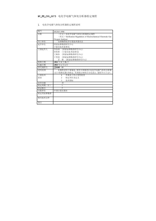
MV_RR_CNG_0073电化学电极气体氧分析器检定规程1. 电化学电极气体氧分析器检定规程说明编号JJG365-1998名称(中文)电化学电极气体氧分析器检定规程(英文)Verification Regulation of Electrochemical Electrode Gas Oxygen Analyser归口单位全国物理化学计量技术委员会起草单位国家标准物质研究中心宁波市技术监督局主要起草人李春瑛 (国家标准物质研究中心)管怡和 (宁波市技术监督局)王林珍 (国家标准物质研究中心)于登甫 (国家标准物质研究中心)茅 锋 (国家标准物质研究中心)批准日期1982年3月31日实施日期1983年1月1日替代规程号JJG365-84适用范围本规程适用于新制造、使用中和修理后电化学电极气体氧分析器(以下简称仪器)的检定。
其刻度以体积百分比表示,量程不小于1%。
主要技术要求1 外观及工作正常性检查2 检定项目及定义3 技术指标是否分级 否检定周期(年) 1附录数目 2出版单位中国计量出版社检定用标准物质相关技术文件备注2. 电化学电极气体氧分析器检定规程摘要一概述电化学电极气体氧分析器主要用于化学工业、冶金工业、电子工业、环保监测、医疗卫生以及航空航天等领域氧含量的测定。
该仪器由电化学电极(液体或固体电解质)气体氧传感器和带有温度补偿的电子显示单元两部分组成。
依气体导入形式分为吸入式和扩散式两种类型,测量程序如图1所示:图1 电化学电极气体氧分析器测量程序图二技术要求1 外观及工作正常性检查1.1 仪器应附有制造厂的技术说明书,并应附件齐全;应标明仪器名称、仪器型号、编号及制造厂名称、制造计量器具许可证标志;各开关、旋钮、显示器应有明确的功能标志。
1.2 仪器通电、通气后,各部分都能正常工作,各调节器应能正常调节,显示器应清晰、稳定地显示测量值。
2 检定项目及定义2.1 残余电流由于电极残余电流引起的指示器零点偏移。
钠离子计检定规程
---
五
检定结果处理和检定周期
11 经检定符合本规程规定指标的仪器为合格仪器,发给检定证书。 12 当电计检定合格,仪器配套检定不合格时,可以更换或处理电极后再检定,检定合 格者为合格仪器,发给检定证书。 13 不合格仪器出具检定结果通知书,并注明不合格项目。 14 在仪器降级使用时,级别按表1规定执行。合格者可发给检定证书,并注明降级使 用。 15 检定周期为1年,但可根据实际情况随时送检。 注:需要查阅全文,请与出版发行单位联系。
表1
仪器级别 参 数 电计示值误差 电计温度补偿器误差 电计输入电流 电计输入阻抗 电计重复性误差 电计绝缘电阻 仪器示值误差 仪器重复性误差 (pNa) (pNa) (A) (Ω) (pNa) (MΩ) (pNa) (pNa)
±0.01 ±0.01 - ≤2×10 12 ≥1×10¹² ≤0.01 ≥20 ±0.04 ≤0.02
四
检定项目和检定方法
7 外观检查 用目测和手感按第2条进行检查。 8 电计检定 在进行8.1至8.5款检定前均应作好如下准备。 将电计先予热30 min,然后按图示接好线路。调节标准器输出为零电位,将开关K接通, 按被检仪器说明书操作。电计温度补偿器定位于25℃,示值为零pNa值。
K
R
标准器
电计
8.1 电计示值误差检定 调节标准器,按附录1逐点向被检电计输出相应电位,记录电计示值。每点重复测量3 次,取平均值pNa 。按下式计算示值误差ΔpNa。 --ΔpNa=pNa-pNa 式中pNa为检定点标称值。 取ΔpNa的最大值为电计示值误差。 8.2 电计温度补偿器误差检定
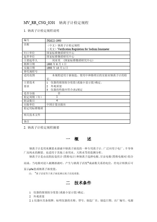
mvrrcng0201钠离子计检定规程钠离子计检定规程说明编号jjg8221993名称中文钠离子计检定规程英文verificationregulationsodiumionometer归口单位国家标准物质研究中心起草单位国家标准物质研究中心主要起草人国家标准物质研究中心批准日期1993实施日期1993年10替代规程号适用范围本规程适用于新制造使用中和修理后的实验室钠离子计的检主要技术要求仪器的性能应符合表1规定是否分级出版单位中国计量出版社检定用标准物质相关技术文件备注钠离子计是用来测量水溶液中钠离子浓度的一种专用离子计广泛应用于电厂半导体厂高纯水的测量
自动电位滴定仪检定规程
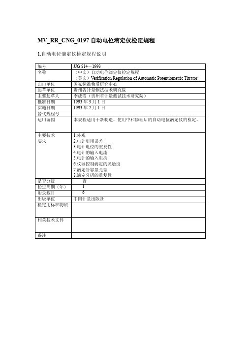
MV_RR_CNG_0197自动电位滴定仪检定规程1.自动电位滴定仪检定规程说明编号 JJG814-1993名称(中文)自动电位滴定仪检定规程(英文)Verification Regulation of Automatic Potentiometric Titrator 归口单位国家标准物质研究中心起草单位贵州省计量测试技术研究院主要起草人李成霞(贵州省计量测试技术研究院)批准日期 1993年3月1日实施日期 1993年7月1日替代规程号适用范围本规程适用于新制造、使用中和修理后的自动电位滴定仪的检定。
主要技术要求1.外观2.电计引用误差3.电计电位的重复性4.电计的输入电流5.电计的输入阻抗6.仪器控制滴定的灵敏度7.滴定管容量允差8.滴定分析的重复性是否分级 否检定周期(年) 1附录数目 6出版单位中国计量出版社检定用标准物质相关技术文件备注2.自动电位滴定仪检定规程摘要一概述自动电位滴定仪(以下简称仪器)是根据电位法原理设计的用于容量分析的常见的一种分析仪器。
电位法的原理是:选用适当的指示电极和参比电极与被测溶液组成一个工作电池,随着滴定剂的加入,由于发生化学反应,被测离子的浓度不断发生变化,因而指示电极的电位随之变化。
在滴定终点附近,被测离子浓度发生突变,引起电极电位的突跃,因此,根据电极电位的突跃可确定滴定终点。
图1所示即为电位滴定曲线,A点是滴定终点。
体积(ml)图 1 电位滴定曲线示意图仪器分电计和滴定系统两大部分。
电计采用电子放大控制线路,将指示电极与参比电极间的电位同预先设置的某一终点电位相比较,两信号的差值经放大后控制滴定系统的滴液速度。
达到终点预设电位后,滴定自动停止。
目前,国产的仪器中电计多可分为指零式和指针直读式两类,而滴定系统可分为活塞控制数字式滴定管和电磁阀控制刻度式滴定管两大类。
国外仪器多为微机控制滴加量,其结构也可分为电计和滴定系统两大部分。
二技术要求1 外观1.1 仪器应有下列标志:仪器名称、型号、器号、制造厂名和出厂日期。
工作毛细管粘度计检定规程

t——一定体积的液体流经毛细管的时间 (s)。
粘度计常数的检定可采用两种方法。
方法1 用标准粘度液 (以下简称标准液) 检定。检定精密粘度计用一级标准液;检定普通
工作粘度计用二级标准液 (参看JJG 2016-87粘度计量器具检定系统)。粘度计的检定应在标准
液的定值温度下进行。
方法2 直接比较法。把被检粘度计与常数标称值相近的基准或标准粘度计置于同一恒温槽
否 2 4 中国计量出版社
相关技术文件
备注
2. 工作毛细管粘度计检定规程摘要
一概 述
重力式毛细管粘度计的工作原理,是用相对法测量一定体积的液体在重力作用下流经毛细
管所需时间,以求得液体的运动粘度。如图所示。运动粘度的计算公式为
v=Ct
(1)
式中 v——液体的运动粘度 (mm2/s);
C——粘度计常数 (mm2/s2);
中,在相同的条件下同时比较同一液体的流动时间来实现。此种液体称为比较液,它可以不是
标准液,但必须是均匀、无杂质的牛顿液体。
111
二 技术要求
(一) 计量性能
1 工作毛细管粘度计应符合表1规定的重复性指标。
(二) 外观质量
2 毛细管粘度计必须用无色透明的仪器玻璃吹制成,粘度计的计时球和毛细管部位不得有 节点、气泡和柳纹。
标准液(1) v1=49.28 mm2/s
329.7
329.7
329.7
329.7
329.9
329.9
329.1(超差)
t1=329.6 ×
t1=329.8
同列重复性
329.9-329.1 329.6
×100%
=0.24% (超差)
329.9-329.7 329.8
MV_RR_CNG_0058容重器检定规程(试行)
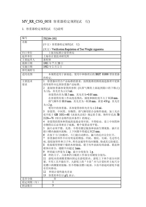
MV_RR_CNG_0058 容重器检定规程(试行)1.容重器检定规程(试行)说明编号JJG264-1981名称(中文)容重器检定规程(试行)(英文)Verification Regulation of Test Weight Apparatus归口单位上海市标准计量管理局起草单位上海市计量技术研究所主要起草人惠程智批准日期 1981年7月20日实施日期 1982年1月1日替代规程号适用范围本规程适用于新制造、使用中和修理后的HGT 01000型容重器的检定。
主要技术要求1 容重器应符合产品标准的要求,按照批准的图纸制造修理中更换的零部件应达到容重器产品标准。
2 新制容重器容量筒的容积(从排气锤的上面起到豁口的下缘止) 为1 L,其允差为±1.5 ml。
容量筒内径为88.5 mm,其允差为+0.05 mm。
在容量筒有效工作高度范围内,圆度和圆柱度不大于0.10 mm。
排气锤外径88.0 mm,其允差为-0.10 mm;质量450 g,其允差为±2 g。
使用中的容重器,其容量筒容积允差为±2.0 ml。
3 容量筒、中间筒、谷物筒、排气锤用铝合金铸件制成。
加工光洁度不低于GB 1031—68《表面光洁度》规定的5级。
铸件针孔按JB 2120—78《铝合金铸件技术条件》的规定。
4 容量筒的筒体和筒底的连接必须牢固,不得松动。
套上中间筒和谷物筒以后必须垂直于底板,整个装置必须平稳。
5 插片必须平整、光滑,不得有镀层脱落和表面生锈现象。
插片在豁口槽内抽插应流畅,上下间隙不得超过0.25 mm。
6 在按下斗门扣板时,斗门能自动弹出,漏斗的孔应完全打开。
7 容重器的零件不应有明显的锈蚀、凹陷、裂纹、尖刺、毛边等毛病。
除铝制零件和刀子外,所有金属零件均应镀镍、铬或其它防腐层。
8 收装箱用坚硬干燥的木材制成。
箱子内外表面均须涂漆。
箱盖和箱体应密合,缝隙不应超过1mm。
9 秤的最大秤量为1 kg,最小分度值为 1 g。
标准温度计检定规程

MV_RR_CNG_0228 标准体温计检定规程1. 标准体温计检定规程说明编号JJG881-1994名称(中文)标准体温计检定规程(英文)Verification Regulation of Standard Clinical Thermometer归口单位中国测试技术研究院起草单位中国测试技术研究院主要起草人魏寿芳(中国测试技术研究院)批准日期 1994年9月10日实施日期 1995年2月1日替代规程号适用范围本规程适用于新制造和使用中的测温在35~45℃范围内、分度值为0.05℃,具有零位刻度的标准体温计的检定。
主要技术要求1 玻璃与毛细管2 水银与水银柱3 刻度与标志4 温度计的部分尺寸5 示值允许误差6 毛细管和刻线等分均匀性的允许误差7 按照本规程检定的温度计的不确定度为±0.020℃(置信概率为0.99)。
是否分级 否检定周期(年) 2附录数目 2出版单位中国计量出版社检定用标准物质相关技术文件备注2. 标准体温计检定规程摘要一概述标准体温计(以下简称温度计),主要用于检定人用体温计、兽用体温计及各种电子体温测试仪,它是利用水银在玻璃感温泡和毛细管内的热膨胀现象来测量温度的。
二技术要求1 玻璃与毛细管1.1 玻璃应光洁透明,在刻度范围内和感温泡上不得有影响读数和强度的缺陷。
1.2 温度计应平直,粗细均匀,不得有明显的弯曲现象。
1.3 毛细管要直,孔径要均匀,毛细管与感温泡、中间泡及安全泡的连接处均应呈喇叭形状.不得有颈缩现象。
1.4 温度计应熔入一条乳白色或其他颜色的釉带,正面观察时,水银柱与全部刻线的投影应在釉带范围内。
2 水银与水银柱2.1 水银必须纯净、干燥、无气泡。
2.2 水银柱不得中断、温度上升时不得有显见的停滞或跳跃现象,温度下降时不得有挂壁现象。
3 刻度与标志3.1 温度计应按90年国际温标刻度。
3.2 温度计的刻线应垂直于毛细管的中心线,刻线应与水银柱相交;刻线和计量数字及其他标志应清晰准确;涂色应牢固耐久。
元素分析仪检定规程1
元素分析仪检定规程1. 元素分析仪检定规程的说明 编号JJG(教委)017-1996 名称 (中文) 元素分析仪检定规程 (英文) Verification regulation for elemental analyze r归口单位 国家教育委员会起草单位 国家教育委员会主要起草人马卿云 批准日期 1997年1月22日实施日期 1997年4月1日替代规程号 无适用范围适用于新安装、使用中和修理后的微量型元素分析仪(以下简称仪器)的检定。
主要技术要求 1. 外观要求2. 安装条件3.检定环境 4.检定设备和试剂 5.检定项目和检定方法 是否分级无 检定周期(年)2 附录数目3 出版单位科学技术文献出版社 检定用标准物质相关技术文件备注2. 元素分析仪检定规程的摘要2 范围适用于新安装、使用中和修理后的微量型元素分析仪(以下简称仪器)的检定。
2.1 原理本仪器用于测定有机物质材料的碳、氢、氮及硫或氧(C 、H 、N 、S / O)元素的含量。
试样在催化氧化(或裂解)-还原管中高温转变为二氧化碳、水蒸气、氮气及二氧化硫或一氧化碳(CO 2、H 2O 、N 2、SO 2或CO)。
然后经吸附分离—热导差检法依次分别测定各自的组分,或经色谱柱将混合气体分离为个别的组分,最后用热导检测器或红外吸收检测器分别测定各组分的响应值。
根据组分的响应值和对应元素的灵敏度(或校正)因子K 值,分别计算样品中各元素的含量。
上述测定过程均按仪器系统规定的操作程序和预设的样品数据自动快速完成。
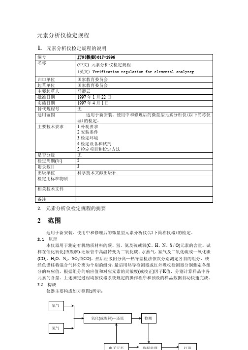
2.2 构成仪器主要构成如方框图1所示:图1 元素分析仪构成方框图2.2.1氧化(或裂解)—还原系统:盛有氧化催化剂的氧化管和盛满还原剂的还原管及其加热炉,或测定硫或氧元素的附件装置。
2.2.2检测系统:氧化(或裂解)—还原产物CO2、H2O、N2及SO2或CO的分离和检测系统。
2.2.3数据处理(或控制)系统:收集检测信号及数据处理或整机控制的微型计算机。
移液枪 校准
(5)
V
式中: n——测试次数; Vi——单次测得值与被测量的平均值之差 (μ1或mm3)。
五 检定结果的处理
14 经检定合格的移液器,发给检定证书;经检定不合格的移液器,发给检定结果通知书。
注:需要查阅全文,请与出版发行单位联系。
张红亚 (上海市计量技术研究所) 1990 年 2 月 26 日 1991 年 1 月 1 日
本规程适用于新制造、使用中和修理后的定量、可调移液器 (以 下简称移液器) 的检定。 1 移液器上应标有制造厂名称或商标、标称容量、产品名称、器号
和出厂年份。 2 外壳塑料件表面应平整、光滑、不得有明显的缩痕、废边、裂纹、 气泡和变形等现象。金属表面镀层应无脱落、锈蚀和起层。 3 按钮上下移动应灵活、分档界限明显,在正确使用情况下不得有 卡住现象。 4 可调移液器的容量调节指示部分在调节范围内转动要灵活,数字 指示要清晰、完整。 5 吸液嘴 (尖) 6 移液器的容量允许误差和重复性应符合表1和表2的规定。 7 移液器的密合性
mvrrcng0141定量可调移液器试行检定规程定量可调移液器试行检定规程说明编号jjg6461990名称中文定量可调移液器试行检定规程英文verificationregulationquantitativeadjustablepipet归口单位上海市技术监督局起草单位上海市计量技术研究所主要起草人上海市计量技术研究所批准日期1990实施日期1991替代规程号适用范围本规程适用于新制造使用中和修理后的定量可调移液器下简称移液器的检定
±1.0
重复性(%)
≤|3.0| ≤|2.0| ≤|1.5| ≤|1.5| ≤|1.0| ≤|0.7| ≤|0.5|
表2 标称容量(μ1 或 mm3)
20 100 200 300
- 1、下载文档前请自行甄别文档内容的完整性,平台不提供额外的编辑、内容补充、找答案等附加服务。
- 2、"仅部分预览"的文档,不可在线预览部分如存在完整性等问题,可反馈申请退款(可完整预览的文档不适用该条件!)。
- 3、如文档侵犯您的权益,请联系客服反馈,我们会尽快为您处理(人工客服工作时间:9:00-18:30)。
Verification VCS with MVSIM MVRC CustomSim Low Power Methodology
• Automated LP assertions and coverage
• Multi-voltage static checks from RTL to transistor-level • Optimized power-state checking (relative always-on validation)
Routed PG netlist UPF”
3
Eclypse Seminar 2010
Power Intent Consistency Checks
Pipe-cleaning power intent
Power Intent - IEEE 1801 (UPF)
Power State Table Isolation Policy Level Shifter Policy Retention Policy
Missing, redundant, incorrect
PD 1 0.7V
LS
PD 2
ON/OFF
Missing Interchanged Illegal routing
ISO
strategy and/or implementation clk Placement, polarity, type, ISO LS ISO enable, etc PD 3 Support for state tables, 0.9V transitions, sequences Proper power / ground connectivity in PG netlist report_protection –intent [–file intent.rpt]
Debugging Failures from MVRC Report Crossprobe selected error
Missing Isolation Cell
Missing Isolation Cell
11
Eclypse Seminar 2010
New MVRC Wizard
Simplifies Setup
Reports
14
Eclypse Seminar 2010
MVRC: Under the Hood
RTL UPF Liberty (.db) • Compiles the RTL files and UPF • Checks and reports syntax and • semantic Reads theerrors initial compiled database • Elaborates design • Creates a multidatabase • voltage Performs structural and power architecture checks on design • Generates reports
Eclypse Seminar 2010
Multi-Voltage Rule Checking & Simulation
May 2010
Eclypse Seminar 2010
1
Eclypse Low Power Solution
Power-aware Verification
• Voltage-level aware simulation
Services Comprehensive verification of advanced LP techniques
2
Eclypse Seminar 2010
C RTL IEEE 1801
● ●
Power-aware Implementation
Power-aware Signoff
MVRC Low Power Static Rule Checker
apdb
MVCMP (Parsing the design) MVDBGEN (Multi-Voltage Elaboration)
MVRC (Static Checks)
Reports
15
Eclypse Seminar 2010
RTL Checks: Suggested commands
# Read the MV Database read_db
4
Eclypse Seminar 2010
Library Consistency Checks
Design (RTL,GL, or PG Netlist) Operating Corner in UPF Operating Corner in Library
MVRC
Mismatch Report
• Operating point in UPF should be subset of that in Library
• Used at netlist stage
Most report_* commands have “-file” option, to send output to a file
9
Eclypse Seminar 2010
Modeling Multi-Voltage Connectivity
1.2V 1.0V 0.9V
• Includes connectivity tracing
6
Eclypse Seminar 2010
Architectural Checks
• Critical functional signals and UPF control signals automatically checked
– – – – – – – – – Clock Clock Enable Reset Scan Enable Isolation Enable Power Enable Power OK Retention Save Retention Restore
Domain 4 1.2V 1.2V 1.2V
1.2V Off Off
Mode2
Memory
Mode3
IO Control Real Time Clock (Battery) ISO_EN
Power Management Unit
Check on ISO_EN signal shows island ordering (i.e., relative alwayson) error: PMU is OFF in Mode 3
MVRC
Mismatch Report
report_protection -critique -no_design_checks
Examples… • Isolation needed but not specified • Isolation specified but not needed • Multiple rails transitioning during power state transitions
INACTIVE POWER DOMAIN
CRITICAL SIGNAL
ACTIVE POWER DOMAIN
report_architecture –island_order
• Users can also add their own signals
report_architecture –island_order -signal <signal_root_pin>
– Voltage_map attribute in Liberty referenced
• Checks on all cell types
– Isolation cells, level shifters, power switches, retention cells, always-on cells, standard cells
Cell level pins must be associated with chip level supply voltages connect_supply_net (UPF) set_related_supply_net (UPF extension)
V2_VDD V1_VDD V3_VDD
12
Eclypse Seminar 2010
Partial Schematic Display
Simplifies Debug
Full Schematic Partial Schematic
Partial Schematic Displays Only Relevant Cross-Over Information
– No testbench or sim cycles needed
UPF’
IC Compiler Architectural, Structural, Functional, PG, & Transistor Checks
MVRC can be used for any design phase
8
Eclypse Seminar 2010
Structural Checks
Checks ISO/LS requirements,
based on PST and UPF strategies, against power management (PM) elements implemented in the design
Implementation
RTL UPF
MVRC
UPF & Library Consistency Checks, and Architectural Checks
