全能视觉软件说明书(视觉)2015.9.28
视觉手册简体
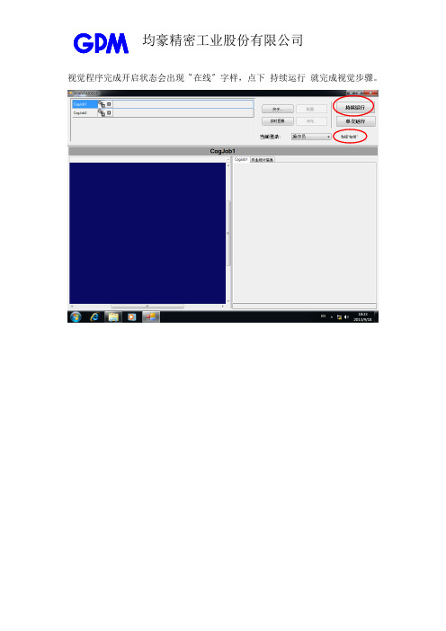
视觉程序完成开启状态会出现〝在线〞字样,点下持续运行就完成视觉步骤。
程序在运行状态会显现停止的按钮当设备发出检测讯号,就会把影像及判定结果显示出来若要修改检测参数,必须先停止运行,在当前登录选择管理员,输入密码。
完成登录后,点选配置按钮,会跳出一窗口再选择QuickBuild选项跳出的程序里面CogJob1代表转盘第6站,CogJob2则为第7站先以CogJob1进行解说,点选Image Source进入Image Source中照相机的闪光灯和触发器选项触发模式原设定为硬件半自动表示是从PLC控制检测,每次参数改完后,这地方都要改回这选项,视觉才能正常进行。
修改参数时为了能够即刻知晓结果,我们会将控制权设定给视觉程序,因此触发模式要选手动或者自由运行皆可。
关掉设定窗口后,点一下左上的三角形图像就能进行取像检测第6站的检测项目有3个,分别为CogSobelEdgeTool1(胶条漏检测)、CogSobelEdgeTool2(试纸区域脏污检测)、CogPatInspectTool1 (外观污损检测)第一个第二个第三个第四个CogSobelEdgeTool1(胶条漏检测)与CogSobelEdgeTool2(试纸区域脏污检测)的瑕疵检测标准可从幅度缩放系数进行变动,数值变大会提高瑕疵缺陷检查能力检测的结果会显示在CogDataAnalysisTool1~4中,出现红色斜线记号者 代表不良NG第一个第二个第三个第四个判定不良的原因能从链接线回找,此范例为CogSobelEdgeTool2的第一个产品右侧的影像有下拉选项,选择LastRun. CogSobelEdgeTool2.FinalMagnitudeImage 就可看到呈现绿色的瑕疵地点直接点进个别产品瑕疵判定也能看见绿色的瑕疵地点CogPatInspectTool1(外观污损检测)需要建立各个产品样本的影像来进行比对进到建立影像窗口,因已经有一个样品影像可以先进行储存,下次用到相同样品时,就能用加载方式执行。
视觉定位软件VisionKit软件说明书完整版
视觉定位软件V i s i o n K i t软件说明书 HEN system office room 【HEN16H-HENS2AHENS8Q8-HENH1688】文件名称:视觉定位软件VisionKit使用说明书文件版本:中文简体版文件页数:共 42 页(含此页)编制:审核:标准化:批准:日期:大族激光科技产业集团股份有限公司视觉定位软件VisionKit使用说明书(版本:中文简体版)大族激光科技产业集团股份有限公司声明版权所有 ? 大族激光科技产业集团股份有限公司保留一切权利。
未经大族激光科技股份有限公司的许可,任何组织和个人不得擅自摘抄、复制文档内容的部分或全部,并不得以任何形式传播。
商标声明和其它大族商标均为大族激光科技产业集团股份有限公司的注册商标,并对其享有独占使用、许可使用、转让、续展等各项法定权利,未经大族激光科技产业集团股份有限公司允许,任何组织或个人不得在商品上使用相同或类似的商标。
注意在所规定的支持保修范围内,大族激光科技产业集团股份有限公司履行承诺的保修服务,超出所在规定的保修范围的,恕不承担保修服务。
对于在使用本产品过程中可能造成的损失,大族激光科技产业集团股份有限公司不承担相关责任。
如发生任何争议,应按中华人民共和国的相关法律解决。
大族激光科技产业集团股份有限公司随时可能因为软件或硬件升级对使用说明书的内容进行更新,所有这些更新都将纳入使用说明书新的版本中,恕不另行通知。
目录一、软件概述视觉定位软件VIsionKit是大族激光科技产业集团股份有限公司光纤打标产品线开发的一款定制的机器视觉定位软件,通过CCD视觉定位后将位置偏差数据发送至打标软件系统进行补偿校正打标,实现产品精确定位打标功能。
视觉定位打标系统通常由CCD定位软件、具有数据通讯和偏位补偿功能的打标软件系统、以及数据通讯网络(COM232或IP/TCP网络)等三大模块组成。
二、环境安装环境要求操作系统:Windows XP以上,推荐Windows 7(32)位系统,暂不支持64位系统。
(完整word版)VISION中文的使用说明
NI Vision 控件模板Vision控件模板位于LabVIEW控件模板的最顶层,由一下元素组成:IMAQ Image.ctl—该控件是一个类型定义,用于声明图象类型的数据。
在V I的前面板中使用该控件代表图象类型数据。
例如,使用该控件作为一个子程序的输入或输出,使调用成成可以将一幅图像传送给子程序。
图像显示(Image Display)—该控件用于在LabVIEW 中直接显示图像。
也可以利用该控件创建关注区域 (ROIs)。
图像显示控件提供标准和3D版两种外观。
IMAQ 视觉控件(IMAQ Vision controls)—这里的控件用于将NI Vision的程序控件直接加入入用户自己的程序中获得相应的功能。
机器视觉控件(Machine Vision controls)—这里的控件用于将NI Vision 的机器视觉控件直接加入到用户自己的程序中以获得相应的功能。
NI Vision 函数模板NI Vision for LabVIEW 由三个主要的函数模板组成:常用视觉程序(Vision Utilities), 图像处理(Image Processing), 和机器视觉(Machine Vision)。
本节介绍这些模板以及它们的子模板。
常用视觉程序(Vision Utilities)常用视觉函数用于在NI Vision中处理和显示图像。
Image Management—管理图像程序组。
利用这些程序可以建立和释放图像,设置和读取图像的属性例如尺寸和偏移量,复制图象。
也可以使用一些高级的V is来定义图像的边框区域以及访问图像数据的指针。
Files—一组使用不同格式读、写图像文件,并从文件中获得所包含的图像的信息的程序模块。
External Display—用于在外部窗口显示图像的程序模块组。
使用这些程序模块可以完成以下任务:读取和设置窗口属性,如尺寸、位置、缩放系数为图像窗口设置调色板建立及使用图像浏览器在图像窗口上为选中的关注区域建立和使用不同的交互式绘图工具。
Magic3DEasyView中文使用说明解读
Magic3DEasyView中文使用说明解读Magic 3D Easy View 软件使用说明序言我们的视觉效果软件可以为您设计的舞台场景提供3D立体效果图。
通过它,您可以预览机械灯具或智能灯具(iris灯、strobe灯等各种舞台灯)所拥有的功能,比如:灯光的运动、颜色和其他效果。
传统的灯具,包括PAR灯的效果也可以在软件中显示。
您可以加入道具来设计个性化舞台场景,比如:从我们的物料库中或是从其他的CAD软件中导入各种支撑架、舞台器具等等。
只需稍稍练习,您就可以设造一个逼真的舞台和场地。
注意:要得到精确的3D显示效果,必须细心建立舞台灯的资料库。
3D效果软件有不同模式,每个模式都可以通过不同的资源(软件、控制台、网络等等)接收DMX信号。
软件还可以同时显示4个DMX 域。
如果连接了一个软件控制器,软件就会自动地在3D软件中创建灯具地址,否则就需手动创建地址。
所有DMX域都遵循相同的规则。
另外,您也可以在软件中划分DMX域,比如域1连接到USB/DMX-IN 接口,而域2连接到Art-Net协议中。
3D软件中的DEMO模式可以让用户用最少的操作创建舞台场景。
但是不可以用这个模式将DMX信号连接到3D软件中。
第一步这一部分介绍了简单使用3D视窗的基本步骤。
它包括一个用来存储节目程序的描述文件和如何创造一个3D舞台场景的第一步。
3D舞台您所创建的3D舞台将会以*.evs 格式的文件被存储起来,并且您可以任意打开、修改及再存储这些文件。
您对舞台进行的所有设置,包括尺寸、颜色、花纹以及您所加入的各种灯光、道具和人物都会被保存在文件之中。
您同样可以在“舞台”的菜单栏中选择“导入/导出”选项,来将3D舞台导入到一个压缩文件中/将3D舞台从一个压缩文件中导出。
我们也可以存储一个舞台和它所需要的所有文件(比如背景图案的X 文件或bmp文件、jpg文件等等),并可以将它们在另一台没有这些文件的电脑上重新打开。
您的第一个舞台场景下面这部分阐述了如何创建第一个舞台的步骤,并向您介绍了3D 软件的基本功能。
机器视觉系统产品操作说明书
一、产品基本功能:本系统是通过两个CCD采集产品图象传到电脑两个显示器的软件上,在显示器上通过肉眼来判断产品是否合格。
因为该系通要通过肉眼检测产品两个不同部位(或同时检测两个产品),所以要用到两个显示器。
在软件中可设置横线,竖线各10条,可以通过移动步长来调整各线条之间的距离。
根据不同的产品设置不同的检测文件,可以检测多种不同的产品。
二、软件 操 作 :1、检测产品:开机后桌面上有可执行文件“Athena427",和“Athena410"为检测程式,双击打开。
点击相机菜单下面的开始菜单,再点击文件菜单下的打开弹出打开对话框,选择要检测产品的线条设置文件就可以检测该产品了。
把其中一个打开文件移动到显示器的一边,该文件就跑到另一个显示器上去了,在该显示器上就可以对该文件进行相关操作。
注意:相机的系列号与检测软件是相对应的。
“Athena427" 检测程式上显示的是427相机拍摄的产品,“Athena410" 检测程式上显示的是410相机拍摄的产品。
2.参数设定说明打开画线菜单下的设定打开设置线条对话框,可以针对不同的产品设置不同的画线。
先根据检测产品的要求先选中对话框中的横线(X1到X10,要几条就选中几条),竖线(Y1到Y10,要几条就选中几条)如下图1我们选中横线3条(X1,X2,X3)竖线3条(Y1,Y2,Y3)。
图1再将横线下面的AIIX换成X1,选择步长后再选择上移或下移就可以根据要求移动线条X1。
如下图2选择步长30点击上移两次后线条X1的位置如下。
其他线条设置也是这样的。
图2线条都设置好后点击文件菜单下的另为存菜单,在文件名下输入要检测产品名称,点击保存就可以保存该产品线条的设置。
如下图3。
这样可以设置并保存多种产品的线条设置文件。
图3还可以根据自己的要求更改每条线条的颜色。
先选中要修改颜色的线条,点击下面对应的颜色板,选中想要修改的颜色就可以了。
如下图4图4----修改线条颜色的操作图4----修改后线条的颜色2.像素大小的确定不同相机像素不同,一个步长就是一个像素。
视觉软件说明文档
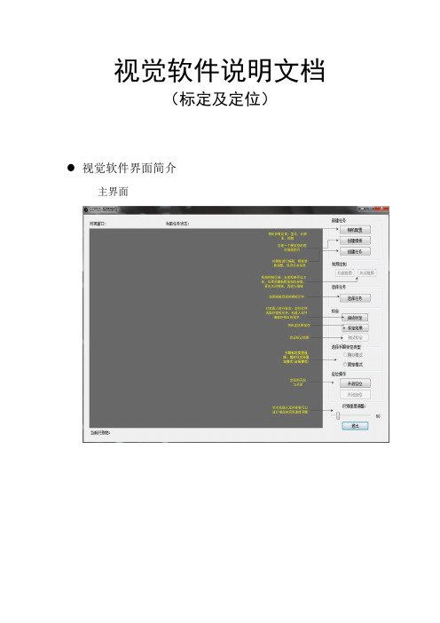
视觉软件说明文档(标定及定位)视觉软件界面简介主界面界面功能模块介绍1.可视窗口:实时视频的显示,物体识别显示,如下图所示:2.当前任务状态:当“鼠标”移动到该位置会弹出浮动提示,将显示当前相机参数,任务数量,模板参数等信息,如下图所示:3.相机配置:暂时只支持映镁精的相机,参数配置如下图所示:4.创建模板:点击按钮后,会自动截取一张完整的相应分辨率大小的图片,然后选取想要的区域,进行保存。
5.创建任务:点击后,会弹出如下窗口:1)选择相应的模板打开模板图片后,选择一个抓取点(这将是匹配参数的一部分) 2)选择算法后会弹出窗口进行参数的调节,如下图所示:注意事项:1.抓取点:不用自己输入(之前打开模板图片选择的抓取点就是改抓取点)2.金字塔层数越高,识别越快(相反的,识别度就会下降,建议选择4)3.边缘阈值下限/上限:上限值始终要保持大于下限值实时调整这项值,窗体下面会进行实时预览显示。
对照下面的判别方式,将值调整到合适为止好坏的判别方式:效果好:如下图效果差:如下图4.角度范围下限/上限:上限值始终要保持大于下限值如果是有角度:比如矩形等:范围一般设置为:0-360如果是没有角度的(或是细微的):比如圆形之类的,范围一般设置为:0-0.1 (上限值绝对不能设置为0)4.匹配阈值:范围是0-1:值越低:匹配度越低(拿类似边缘的也有可能识别到,对环境要求较低)值越高:匹配度越高(比如设置为1,那么将匹配一模一样的才行,对环境较高)推荐设置:光源做好后,匹配度一般设置为0.7-0.9之间6.保存好模板参数,保存任务名(请保存到当前视觉软件TaskTemplate目录下,格式为.ini)7.选择任务:任务支持单选,多选,追加8.启动标定:将相机固定好,并调整好位置,光源做好;选择好模板任务后,机器人软件:标定程序配置完毕后,点击按钮就能进行对机器人的标定。
标定时间需要15分钟左右!标定之前,请先启动机器人软件,标定模式为:固定模式(全局模式)9.标定结果:待标定完成后,点击此按钮,将会把标定文件保存到当前视觉软件CalibData目录下文件名为:calibration001.yml10.测试标定:测试标定文件是否正确,精度知否达标,视觉软件识别到物体后,机器人能否正确的抓取到识别物!操作简介:1:机器人操作软件,利用视觉模块编辑一段视觉相关的程序(具体参考机器人软件操作说明书)2:视觉定位软件,选择好手眼标定文件:点击“固定模式”复选框,选择calibration001.yml标定文件3:点击“测试标定”按钮即可观察11.手眼标定类型的选择暂时只支持固定模式,点击“固定模式”复选框,选择calibration001.yml标定文件12.开启定位选择好任务,手眼标定文件,点击此按钮就能和机器人软件配合做定位识别了13.关闭定位将停止定位识别14.识别速度调整在实际应用中,机器人软件编好程序后,里面将会用来延时等相关操作控制视觉定位,这个选项能配合机器人软件,通过调整参数值,达到想要的识别速度视觉标定操作(机器人部分)一,概述视觉标定的思路为:使用多个特征点分别在图像坐标系的像素坐标和机器人的空间坐标,来求得两个坐标系之间的影射关系。
ADLINK EOS-JNX系列视觉软件功能参考手册说明书
ADLINK Vision Software (AVS) for EOS-JNX SeriesFunction Reference ManualManual Revision: 1.0Revision Date: February 17, 2022Part No: 50M-00066-1000Revision HistoryiiADLINK Vision Software for EOS-JNX SeriesPrefaceCopyright © 2022 ADLINK Technology, Inc.This document contains proprietary information protected by copy-right. All rights are reserved. No part of this manual may be repro-duced by any mechanical, electronic, or other means in any formwithout prior written permission of the manufacturer.DisclaimerThe information in this document is subject to change without priornotice in order to improve reliability, design, and function and doesnot represent a commitment on the part of the manufacturer.In no event will the manufacturer be liable for direct, indirect, spe-cial, incidental, or consequential damages arising out of the use orinability to use the product or documentation, even if advised ofthe possibility of such damages.Environmental ResponsibilityADLINK is committed to fulfill its social responsibility to globalenvironmental preservation through compliance with the Euro-pean Union's Restriction of Hazardous Substances (RoHS) direc-tive and Waste Electrical and Electronic Equipment (WEEE)directive. Environmental Protection is a top priority for ADLINK.We have enforced measures to ensure that our products, manu-facturing processes, components, and raw materials have as littleimpact on the environment as possible. When products are at theirend of life, our customers are encouraged to dispose of them inaccordance with the product disposal and/or recovery programsprescribed by their nation or company.TrademarksProduct names mentioned herein are used for identification pur-poses only and may be trademarks and/or registered trademarksof their respective companies.iiiPrefaceConventionsTake note of the following conventions used throughout this manual to make sure that users perform certain tasks and instructions properly.Additional information, aids, and tips that help users performtasks.Information to prevent minor physical injury, component dam-age, data loss, and/or program corruption when trying to com-plete a task.Information to prevent serious physical injury, componentdamage, data loss, and/or program corruption when trying tocomplete a specific task.iv PrefaceADLINK Vision Software for EOS-JNX SeriesTable of ContentsRevision History (ii)Preface (iii)1Introduction (1)1.1Environment (1)1.2AVS Installation (1)1.3AVS Functions & Parameters (1)1.4AVS Sample Programs (1)1.5AVS Installation Folder (2)1.6Sample Reference Code (2)1.6.1Include Header File (2)1.6.2Get Product Handle (3)2AVS Parameters Reference (5)2.1Product Name (5)2.2Product Features (5)2.3Edge Trigger (5)2.4PoE (6)2.5PoE Power Management (7)2.6DIO Capabilities (7)2.7DI Capabilities (8)2.8DO Capabilities (8)2.9Signal Edge Trigger Type (8)2.10AVS Error Code (9)3Function Library (11)3.1List of Functions (11)3.2Function Library (12)3.2.1Common (12)3.2.2Power over Ethernet (17)3.2.3Digital Input/Output (24)vImportant Safety Instructions (33)Getting Service (37)viIntroduction 1ADLINK Vision Software for EOS-JNX Series1IntroductionADLINK Vision Software (AVS) is the application programming interface (API) for the ADLINK EOS-JNX series of products. AVS allows developers to build applications in Linux via C/C++. Along with the APIs, AVS also includes product drivers and a set of sam-ple programs and documentation.1.1Environment1.2AVS Installation1.3AVS Functions & Parameters1.4AVS Sample Programs1.5AVS Installation Folder1.6Sample Reference Code1.6.1Include Header FileThis code sample shows how to include a header file.#include "/usr/local/include/ADLINK/AVS/AVS_SDK.h"#include "/usr/local/include/ADLINK/AVS/Common/I_common.h"2 IntroductionADLINK Vision Software for EOS-JNX Series1.6.2Get Product HandleThis code sample shows how to get the product handle andproduct Information.using namespace std;/*Show SDK Information*/char buffer[256];if (AVS_GetSDKInfo(buffer, sizeof(buffer)) ==AVS_FUN_SUCCESS)cout << buffer << endl;.../*Show Product Information*/unsigned int nums = AVS_GetProductNums();if (nums <= 0){cout << "Find no device!" << endl;return 0;}void* handle;unsigned int devIndex = 0;handle = AVS_GetProductHandle(devIndex);if (!handle){cout << "AVS_GetProductHandle Error\n" <<endl;return 0;}if (AVS_GetProductInfo(handle, buffer,sizeof(buffer)) == AVS_FUN_SUCCESS)cout << buffer << endl;...3IntroductionThis page intentionally left blank.4 IntroductionADLINK Vision Software for EOS-JNX Series2AVS Parameters ReferenceAVS parameters are grouped by enumerations and can be found in the header file “I_common”.2.1Product NameADLINK vision products supported by AVS SDK are grouped by AVS_PRODUCT_TYPE.2.2Product FeaturesAVS parameters are grouped by AVS_FEATURE_TYPE.2.3Edge TriggerEdge Trigger parameters are defined byAVS_ EDGETRIGGER_TYPE.AVS Parameters Reference 52.4PoEPoE parameters are defined by AVS_POEPROPERTY_TYPE.6AVS Parameters ReferenceADLINK Vision Software for EOS-JNX Series 2.5PoE Power ManagementPoE Power Management parameters are defined byAVS_POEPORTPROPERTY_TYPE.2.6DIO CapabilitiesDIO Capability parameters are defined byAVS_DIOCAPABILITY_TYPE.AVS Parameters Reference 72.7DI CapabilitiesDI Capability parameters are defined byAVS_DIODICAPABILITY_TYPE.2.8DO CapabilitiesDO Capability parameters are defined byAVS_DIODOCAPABILITY_TYPE.2.9Signal Edge Trigger TypeSignal Edge Trigger Type parameters are defined byAVS_EDGETRIGGER_TYPE.8AVS Parameters ReferenceADLINK Vision Software for EOS-JNX Series 2.10AVS Error CodeAn AVS error code is defined by AVS_FUN_RETURNVAL. No error occurs if the API returns a value >= 0, or a negative value.AVS Parameters Reference 9This page intentionally left blank.10AVS Parameters ReferenceADLINK Vision Software for EOS-JNX Series 3Function Library3.1List of FunctionsFunction Library 113.2Function LibraryAVS supports the C/C++ programming languages. The following are examples of the C/C++ library.3.2.1CommonThese functions are used to get the product handle and retrieve device information.3.2.1.1AVS_GetProductNums12 Function LibraryADLINK Vision Software for EOS-JNX Series 3.2.1.2AVS_GetSDKInfo3.2.1.3AVS_GetProductHandleFunction Library 133.2.1.4AVS_GetProductInfo14 Function LibraryADLINK Vision Software for EOS-JNX Series 3.2.1.5AVS_GetProductType3.2.1.6AVS_GetProductSN3.2.1.7AVS_GetFeatureListADLINK Vision Software for EOS-JNX Series 3.2.2Power over EthernetThis feature is for SmartPoE, the PoE power management func-tions.3.2.2.1AVS_PoEGetPortNums3.2.2.2AVS_PoESetPortEnable3.2.2.3AVS_PoEGetPortEnableADLINK Vision Software for EOS-JNX Series 3.2.2.4AVS_PoESetPowConsumCalcModel3.2.2.5AVS_PoEGetPowConsumCalcModel3.2.2.6AVS_PoESetProtectTempRangeADLINK Vision Software for EOS-JNX Series 3.2.2.7AVS_PoEGetProtectTempRange3.2.2.8AVS_PoEGetPropertyADLINK Vision Software for EOS-JNX Series 3.2.2.9AVS_PoEGetPortProperty3.2.3Digital Input/OutputThe AVS SDK DIO feature is used to control and configure digital input and output. AVS_DIOGetCapability(),AVS_DIOGetDICapability() and AVS_DIOGetDOCapability() are used to check the supported functions of each product. The digital output can be a general digital output or a triggerable device in the AVS SDK.3.2.3.1AVS_DIOGetCapabilityADLINK Vision Software for EOS-JNX Series 3.2.3.2AVS_DIOGetDINums3.2.3.3AVS_DIOGetDONumsFunction Library 253.2.3.4AVS_DIOGetDICapability26 Function LibraryADLINK Vision Software for EOS-JNX Series 3.2.3.5AVS_DIOGetDOCapabilityFunction Library 273.2.3.6AVS_DIOSetDOState3.2.3.7AVS_DIOSetDOStates28 Function LibraryADLINK Vision Software for EOS-JNX Series 3.2.3.8AVS_DIOGetDIState3.2.3.9AVS_DIOGetDIStatesFunction Library 293.2.3.10AVS_DIOSetDITriggerCallback30 Function LibraryADLINK Vision Software for EOS-JNX Series 3.2.3.11AVS_DIOSetDIEdgeTriggerFunction Library 313.2.3.12AVS_DIOGetDIEdgeTrigger32 Function LibraryADLINK Vision Software for EOS-JNX Series Important Safety Instructions For user safety, please read and follow all instructions, Warnings, Cautions, and Notes marked in this manual and on the associated device before handling/operating the device, to avoid injury or damage.S'il vous plaît prêter attention stricte à tous les avertissements et mises en garde figurant sur l'appareil , pour éviter des blessures ou des dommages.X Read these safety instructions carefullyX Keep the User’s Manual for future referenceX Read the Specifications section of this manual for detailed information on the recommended operating environment X The device can be operated at an ambient temperature of 50ºCX When installing/mounting or uninstalling/removing device;or when removal of a chassis cover is required for user ser-vicing:Z Turn off power and unplug any power cords/cablesZ Reinstall all chassis covers before restoring power X To avoid electrical shock and/or damage to device:Z Keep device away from water or liquid sourcesZ Keep device away from high heat or humidityZ Keep device properly ventilated (do not block or cover ventilation openings)Z Always use recommended voltage and power sourcesettingsZ Always install and operate device near an easily acces-sible electrical outletZ Secure the power cord (do not place any object on/over the power cord)Z Only install/attach and operate device on stable surfaces and/or recommended mountingsX If the device will not be used for long periods of time, turn off and unplug from its power sourceImportant Safety Instructions 3334 Important Safety Instructions XNever attempt to repair the device, which should only be serviced by qualified technical personnel using suitable tools X A Lithium-type battery may be provided for uninterruptedbackup or emergency power.XThe device must be serviced by authorized technicians when:Z The power cord or plug is damaged Z Liquid has entered the device interior Z The device has been exposed to high humidity and/or moisture Z The device is not functioning or does not function according to the User’s Manual Z The device has been dropped and/or damaged and/or shows obvious signs of breakage XDisconnect the power supply cord before loosening the thumbscrews and always fasten the thumbscrews with a screwdriver before starting the system up XIt is recommended that the device be installed only in a server room or computer room where access is:Z Restricted to qualified service personnel or users familiar with restrictions applied to the location, reasons therefor, and any precautions required Z Only afforded by the use of a tool or lock and key, or other means of security, and controlled by the authority responsible for the location X If PoE (Power over Ethernet) is enabled for the device, thesystem can ONLY be deployed indoors. Unless otherwise noted, the PoE system is NOT designed to withstand the rigors of outdoor use.Risk of explosion if battery is replaced with one of an incorrect type; please dispose of used batteries appropriately.Risque d’explosion si la pile est remplacée par une autre de type incorrect. Veuillez jeter les piles usagées de façon appro-priée.ADLINK Vision Software for EOS-JNX SeriesImportant Safety Instructions 35This page intentionally left blank.36Important Safety InstructionsADLINK Vision Software for EOS-JNX SeriesGetting ServiceAsk an Expert:ADLINK Technology, Inc.No. 66, Huaya 1st Rd., Guishan DistrictTaoyuan City 333411, TaiwanTel: +886-3-216-5088Fax: +886-3-328-5706Email:**********************Ampro ADLINK Technology, Inc.6450 Via Del OroSan Jose, CA 95119-1208, USATel: +1-408-360-0200Toll Free:+1-800-966-5200 (USA only)Fax: +1-408-600-1189Email:*******************ADLINK Technology (China) Co., Ltd.300 Fang Chun Rd., Zhangjiang Hi-Tech ParkPudong New Area, Shanghai, 201203 ChinaTel: +86-21-5132-8988Fax: +86-21-5132-3588Email:*********************ADLINK Technology GmbHHans-Thoma-Straße 11D-68163 Mannheim, GermanyTel: +49-621-43214-043214-30Fax: +49-621Email:*******************Please visit the Contact page at for informa-tion on how to contact the ADLINK regional office nearest you:Getting Service 37。
视觉定位软件VisionKit-软件说明书
文件名称:视觉定位软件VisionKit使用说明书文件版本:中文简体版文件页数:共 42 页(含此页)编制:审核:标准化:批准:日期:大族激光科技产业集团股份视觉定位软件VisionKit使用说明书(版本:中文简体版)大族激光科技产业集团股份.hanslaser.声明所有©大族激光科技产业集团股份保留一切权利。
未经大族激光科技股份的许可,任何组织和个人不得擅自摘抄、复制文档容的部分或全部,并不得以任何形式传播。
商标声明和其它大族商标均为大族激光科技产业集团股份的注册商标,并对其享有独占使用、许可使用、转让、续展等各项法定权利,未经大族激光科技产业集团股份允许,任何组织或个人不得在商品上使用相同或类似的商标。
注意在所规定的支持保修围,大族激光科技产业集团股份履行承诺的保修服务,超出所在规定的保修围的,恕不承担保修服务。
对于在使用本产品过程中可能造成的损失,大族激光科技产业集团股份不承担相关责任。
如发生任何争议,应按中华人民国的相关法律解决。
大族激光科技产业集团股份随时可能因为软件或硬件升级对使用说明书的容进行更新,所有这些更新都将纳入使用说明书新的版本中,恕不另行通知。
目录声明 (3)一、软件概述 (5)二、环境安装 (5)2.1环境要求 (5)2.2软件安装 (5)2.2.1 安装halcon基础软件 (5)2.2.2 安装相机驱动软件 (6)2.2.3注册串口通讯组件 (10)2.2.4 VIsionKit软件 (10)三、软件界面介绍 (10)3.1主界面 (10)3.1.1 主界面介绍 (10)3.1运行界面 (13)3.1.1 运行界面介绍 (13)3.2设置界面 (15)3.2.1 图像标定 (16)3.2.2 ROI设置 (18)3.2.3通信设置 (20)3.2.4 LED设置 (21)3.3参数界面 (22)3.3.1编辑定位集 (23)3.3.2定位模板下拉框 (23)3.3.3测试 (24)3.4诊断界面 (25)3.4.1图像操作 (25)3.4.2验证补偿 (27)3.4.3整体补偿 (27)四、CCD工作流程 (28)4.1相机标定 (28)4.2模板制作 (34)4.3生产运行 (38)4.4 误差校正 (40)五、软件操作注意事项 (42)附录A:软件定制功能 (42)附录B:术语解释 (42)附录C:技术支持与服务 (42)一、软件概述视觉定位软件VIsionKit是大族激光科技产业集团股份光纤打标产品线开发的一款定制的机器视觉定位软件,通过CCD视觉定位后将位置偏差数据发送至打标软件系统进行补偿校正打标,实现产品精确定位打标功能。
全能视觉软件说明书视觉2015928

视觉联机激光控制软件-使用说明书-深圳市智远数控有限公司目录上层软件使用操作说明第一章驱动和软件的安装 (2)1.1 数控系统软件简介 (3)1.2 控制系统的组成 (3)1.3 驱动和软件的安装 (3)1.3.1视觉驱动MIL的安装与卸载 (4)1.3.2视觉切割软件的安装 (10)1.4软件特点 (13)1.5单反相机应用步骤 (14)1.6界面说明 (15)第二章设备参数的设置 (17)第三章工作面板 (21)3.1 图层管理 (21)3.2 手动控制 (23)3.2.1标定管理 (24)3.2.2 模版切割设置 (29)3.2.3 寻边切割设置 (38)3.2.4寻边切割功能对材料要求 (40)3.3设备控制 (40)3.4加工信息 (41)底层软件/硬件使用说明及接线 (42)第一章概述 (42)1.1 系统功能 (42)第二章安装接线说明 (43)2.1 安装尺寸 (43)2.2 接线说明 (44)2.21 接口板 (44)2.22 接线图 (44)2.3 端口定义说明 (47)2.32 U盘接口 (48)2.33 PC接口 (48)2.34 网络接口 (48)2.35 端口定义 (48)第三章常见问题排除 (51)3.1 电脑连接问题 (51)3.2 U盘读写问题 (51)3.3 相机连接问题 (51)3.4 问题现象: (51)3.5 机器不动作 (52)第四章经典激光切割机接线图 (53)4.1 标准激光切割机接线图 (53)第一章驱动和软件的安装1.1 数控系统软件简介PowerCut视觉激光切割控制软件是深圳市智远数控有限公司集多年行业经验、业内知名研发团队精心打造的一款激光切割数控精品。
该软件简单易学、运动控制算法成熟稳定、切割工艺完备、人机交互界面友好,适用于服装、亚克力、家俱等非金属激光切割控制。
1.2 控制系统的组成控制系统由硬件(运动控制卡及配件)和软件两部分组成。
亚为机器视觉通用平台 EVPS3.0 使用说明说明书

亚为机器视觉通用平台EVPS3.0使用说明武汉亚为电子科技有限公司2020.08特别声明:本平台为我司技术员友情提供的一个开源自学平台,仅供个人学习和研究使用,未经允许,不得作为商业用途或者另行转卖。
我司提供的密码只保证购买者本人正常使用。
程序不提供修改服务,不对客户具体的项目应用负责。
如需其他功能或二次开发,需与我司以项目的形式进行或请用户自行研发。
如发现bug,敬请告知,公司会及时修改完善,并可能做不定期升级,但不对具体用户负责。
★★★如有任何疑问,可加亚为测控售后QQ:3075964420。
欢迎各位用户和业内外人士技术上的交流和探讨。
目录一、概述 (1)二、使用条件 (1)(一)适用对象 (1)(二)类型说明 (1)(三)相关下载 (2)三、系统简介 (5)(一)功能说明 (5)(二)使用方法 (5)(三)注意事项 (5)四、软件界面 (6)五、功能介绍 (7)(一)测距 (7)(二)放大 (8)(三)旋转 (9)(四)图像标注 (9)(五)图像裁剪 (10)(六)FFT变换 (10)(七)描边 (11)(八)直方图 (11)(九)边缘跟踪 (12)(十)对象素描 (12)(十一)颜色识别 (13)(十二)图片对比 (13)(十三)颜色增强 (14)(十四)字符识别 (14)(十五)几何匹配 (15)(十六)二维码识别 (16)(十七)条形码识别 (16)(十八)控制与采集 (17)(十九)目标跟踪 (17)(二十)目标计数 (18)六、异常处理 (2)(一)软件无法打开 (2)(二)界面错乱 (2)(三)软件无法运行 (2)亚为机器视觉通用平台EVPS3.0使用说明武汉亚为电子科技有限公司一、概述该平台基于LabVIEW2017开发,支持绝大部分国内外的相机。
国外的相机,基本上可以直接使用NI的IMAQdx驱动进行驱动,而国内的,很多都是提供DLL供LV调用。
EVPS机器视觉平台是利用机器代替人眼实现了自动测量和智能控制,目前已集成30大类自适应算法,并获得专利。
视觉系统快速导入手册说明书

前言关于本手册本手册为视觉系统操作的快速入门手册,旨在短时间内提升客户对视觉系统的熟知度,能够较容易掌握一些简单的操作。
操作前提在使用视觉系统前,请务必仔细阅读产品的相关使用说明,用户需在了解视觉系统的基础知识后再使用。
目标群体⏹操作人员⏹应用工程师⏹集成工程师⏹技术售后工程师常见标识含义手册中出现标识及其含义详见下表1。
表1 本文中使用的标识手册说明本手册内容会有补充和修改,请定时留意我公司网站,及时下载最新版本的手册。
我公司网站网址:/目录前言 (I)目录 (I)1拆箱检查 (1)2安装与调试 (4)2.1视觉系统电气连接概览 (4)2.2视觉系统硬件接线说明 (5)2.2.1显示器和视觉控制器接线 (5)2.2.2相机和视觉控制器接线 (6)2.2.3光源和光源控制器接线 (7)2.3相机与光源调试 (8)2.3.1调节光源 (8)2.3.2配置相机 (8)2.3.3打开工程 (11)2.3.4设置相机参数 (12)2.3.5图像质量精调 (13)2.4视觉软件程序调试 (14)3通讯设置 (15)3.1TCP/IP连接前准备 (15)3.2创建视觉TCP设备 (16)3.3格式化发送字符串 (17)3.4发送数据 (18)3.5运行 (19)3.6机器人设置 (20)4视觉坐标系标定 (22)5视觉与机器人联合标定 (26)5.1视觉坐标系和机器人工件坐标系静态联合标定 (26)5.2视觉返回工件坐标的动态修正 (29)附录A 随机文档列表和说明 (30)1拆箱检查视觉系统一般由图像采集装置(相机+镜头)、光源(包括光源控制器)、图像处理系统(视觉控制器+显示器,包括视觉系统所使用的软件)等组成,参考图1-1。
图1-1 视觉系统组成视觉系统的产品到达后应清点发货清单,检查产品零配件是否齐全,检查产品型号是否匹配,如出现问题,请及时与本公司售后人员联系。
表1-1 标准清单说明视觉系统快速导入手册拆箱检查视觉系统快速导入手册拆箱检查视觉系统快速导入手册 安装与调试2 安装与调试2.1 视觉系统电气连接概览在安装视觉系统之前,本公司售前技术人员需要根据项目需求,出具《视觉应用方案设计》文档。
联想 万全慧眼IV高级版 说明书
第二章 联想万全慧眼远程管理模块概述 .............................................................4 2.1 联想万全慧眼高级版特性 ...................................................................................... 4 2.2 支持的操作系统 ..................................................................................................... 5 2.2.1 服务器系统 .................................................................................................... 5 2.2.2 客户端系统 .................................................................................................... 5
视觉科技视觉技术解决方案生成器用户指南说明书
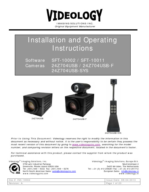
Prior to Using This Document: Videology reserves the right to modify the information in this document as necessary and without notice. It is the user’s responsibility to be certain they possess the most recent version of this document by going to , searching for the model number, and comparing revision letters on the respective document, located in the document’s footer. For technical assistance with this product, please contact the supplier from whom the product was purchased.Videology® Imaging Solutions, Inc. Videology® Imaging Solutions, Europe B.V.37M Lark Industrial ParkwayGreenville, Rhode Island 02828 USATel: (401) 949 – 5332 Fax: (401) 949 – 5276North/South American Sales: **********************Neutronenlaan 45405 NH Uden, The NetherlandsTel: +31 (0) 413 256261 Fax: +31 (0) 413 251712European Sales: *****************www.videology.nlOriginal Equipment Manufacturer24Z704USB24Z704USB-SYS24Z704USB-FLicense Agreement (Software):This Agreement states the terms and conditions upon which Videology Imaging Solutions, Inc. USA and Videology Imaging S olutions, B.V. Europe (hereafter referred to as "Videology®") offer to license to you the software together with all related documentation and accompanying items including, but not limited to, the executable programs, drivers, libraries, and data files associated with such software.The Software is licensed, not sold, to you for use only under the terms of this Agreement.Videology grants to you, the purchaser, the right to use all or a portion of this Software provided that the Software is used only in conjunction with Videology's family of products.In using the Software you agree not to:•Decompile, disassemble, reverse engineer, or otherwise attempt to derive the source code for any Product (except to the extent applicable laws specifically prohibit such restriction);•Remove or obscure any trademark or copyright notices.Limited Warranty (Hardware and Software):ANY USE OF THE SOFTWARE OR HARDWARE IS AT YOUR OWN RISK. THE SOFTWARE IS PROVIDED FOR USE ONLY WITH VIDEOLOGY'S HARDWARE. THE SOFTWARE IS PROVIDED FOR USE "AS IS" WITHOUT WARRANTY OF ANY KIND, TO THE MAXIMUM EXTENT PERMITTED BY LAW, VIDEOLOGY DISCLAIMS ALL WARRANTIES OF ANY KIND, EITHER EXPRESS OR IMPLIED, INCLUDING, WITHOUT LIMITATION, IMPLIED WARRANTIES OR CONDITIONS OF MERCHANTABILITY, QUALITY AND FITNESS FOR A PARTICULAR APPLICATION OR PURPOSE. VIDEOLOGY IS NOT OBLIGATED TO PROVIDE ANY UPDATES OR UPGRADES TO THE SOFTWARE OR ANY RELATED HARDWARE.Limited Liability (Hardware and Software):In no event shall Videology or its Licensor's be liable for any damages whatsoever (including, without limitation, incidental, direct, indirect, special or consequential damages, damages for loss of business profits, business interruption, loss of business information, or other pecuniary loss) arising out of the use or inability to use this Software or related Hardware, including, but not limited to, any of Videology's family of products.Table of Contents1.Document History (4)2.General Descriptions (4)3.Specifications (5)4.Dimensions (6)4.1.24Z704USB (6)4.2.24Z704USB-F (6)4.3.24Z704USB-SYS (7)5.Minimum Computer System Requirements (8)6.Setup and Operation (9)6.1.Flash Camera Setup (24Z704USB-F) (9)6.1.1.Attaching the Illuminator on top of Flash Camera (9)6.1.2.Wiring and Power (9)6.1.3.Subject Distance (10)6.1.4.Flash Intensity (10)6.1.5.White Balance (11)B System Setup (24Z704USB-SYS) (12)6.2.1.Camera Placement (12)6.2.2.Control Panel (12)6.2.3.Power Connection (12)puter Connection (12)6.2.5.Illumination Control (12)6.2.6.Securing the System to the table top (12)7.Software (13)7.1.SFT-10002 USB Viewer Installation (13)ing the Videology Viewer (15)7.3.Basic Camera Controls (16)7.3.1.Zoom Control (17)7.3.2.Brightness (17)7.3.3.Exposure Control (17)7.3.4.Image Orientation Control (17)7.3.5.Image Capture Control (Snapshot) (17)7.4.Advanced Camera Functions (18)7.4.1.Manual White Balance (18)7.4.2.Focus (19)7.4.3.Shutter Speed (19)er Presets (19)7.5.TWAIN Data Source Installation (21)7.6.TWAIN USER Interface (22)8.Contact Information (23)1. Document History2. General DescriptionsThe camera and system are supplied with a software application for camera viewing and control. An SDKis also available for users who wish to integrate the viewing and control features into their own applications.The 24Z704USB camera is a standalone camera; it is not adaptable to the 24Z704USB-SYS system.• 2 megapixel progressive scan sensor• WDM, TWAIN, DirectX/DirectShow compatible • Still image capture with streaming video • Autofocus, 10x optical zoom• FIPS 201 compliance (in conjunction with appropriate software)The 24Z704USB-F camera has a Led Illuminator designed for use with the Videology 24Z704USB Autofocus Zoom Camera. It uses a powerful white LED to provide very bright scene illumination at distances up to 20 feet.• The intensity of the illumination can be varied using a small control wheelon the side of the illuminator.• The flash is controlled directly from the PC, and is triggered whenever asnapshot command is issued. This can be done from within the Videology Viewer Application, or by implementing the Flash Trigger provided as part of the camera SDK.• An In-Line Hub and Control unit is provided so that the flash unit may beeasily retrofitted to existing Zoom Cameras.The 24Z704USB-SYS is an ID badging system utilizing a 2 Megapixel Autofocus USB Zoom camera module and high brightness LED illuminator. It is designed for table top use, and provides high quality streaming video and single frame snapshot capabilities.• 2 megapixel progressive scan sensor• WDM, TWAIN, DirectX/DirectShow compatible • Still image capture with streaming video • Autofocus, 10x optical zoom• Cool energy efficient white LEDs replace “hot” incandescent light or flashand last 1000x longer• On/Off & dimming for LEDs• No shadows or hotspots due to lighting placement • Heavy steel construction • Flexible gooseneck stand• Small footprint saves table space• FIPS 201 compliance (in conjunction with appropriate software)RevisionIssue DateReason CN# Rev A 06-20-13 Initial release, replacing “24Z704USB family” manual 13-10333. SpecificationsEnvironmental Operating Temp. -10°C ~ 50°C (recommended 5° C ~ 40° C)Government ComplianceFIPS 201In conjunction with appropriate softwareElectrical24Z704USB 24Z704USB-F 24Z704USB-SYSImage Sensor 1/3” CMOS progressive scanActive Pixels (HxV) 1280 x 1024 Total Pixels (HxV) 1600 x 1200 Pixel Size3.0µm x 3.0µm Scanning SystemProgressive Scan Scanning Frequency (HxV) 19.5KHz x 15HzResolution 800 TVL Sensitivity1 lux (30 IRE) Display Resolution 1280 x 1024 Still Capture1280 x 1024 pixels Signal To Noise Ratio ≤ 40dB (max)Synchronization InternalScan Mode Progressive scanFlickerless Mode Yes (always on, NTSC/PALconfigurable)Contour Enhancement Yes (text mode or image mode)Mirror ModeYes(horizontal, horizontal + vertical)Positive/Negative Mode Yes Video OutputUSB 2.0 Control Communication USB busShutter Speed 1/20 - 1/1000 sec. White Balance Auto/manual Brightness Manual IrisAuto/manualPower Supply12VDC (10 - 14VDC) Power Consumption Camera is 1 Amp Max System is 3 AmpsSpecial Functions Freeze,H/V reverse, save & recall imagesLighting(24Z704USB-SYS only)6 lensed super bright LEDsUSB VideoVideo CaptureYes (via software) High Resolution Still Image CaptureYes (via software) Supported Image Formats Uncompressed YUV422USB BandwidthUSB 2.04.Dimensions 4.1.24Z704USBThe overall dimensions of the camera are shown in Figure 1.Figure 1.Overall Camera Dimensions4.2.24Z704USB-FThe overall dimensions of the flash camera are shown in Figure 2.Figure 2.Overall USB Flash Camera Dimensions USB connectorPowerFlashUSB connectorPower4.3.24Z704USB-SYSThe heavy-duty steel construction of both the stand and camera housing make for a robust and durable design. A flexible gooseneck mount permits the camera to be tilted from back to front or side to side. The overall dimensions of the USB system are shown in Figure 3.Figure 3.Overall USB System Dimensions5.Minimum Computer System RequirementsA PC with USB 2.0 compatible port.USB 1.1 not supported.MAC is not supported.Preview only•PIII- 1.1GHz or above•128MB of RAM (256MB preferred)•Windows XP/2000 for USB2.0•DirectX/DirectShow 9.0c or later•Windows XP Service Pack 1 (Service Pack 2 Preferred) Windows 2000 Service Pack 4 Preview and capture at the same time•Full D1 MPEG 2 - P4 – 2.4GHz or above•640 x 480 MPEG 2 - P4 – 2.0GHz or above•352 x 288 MPEG1 - P4 – 1.5GHz or above•Hard Disk - 5400RPM or above (7200RPM preferred)•128MB of RAM (256MB preferred)•Windows XP/2000 for USB2.0•DirectX/DirectShow 9.0c or later•Windows XP Service Pack 1 (Service Pack 2 Preferred) Windows 2000 Service Pack 4 Verify system has the latest USB 2.0 host driver from Microsoft® only.Verify that USB host controller chipset is Microsoft certified.This product is not guaranteed to operate with a USB 2.0 host driver from OWC.6.Setup and Operation6.1.Flash Camera Setup (24Z704USB-F)6.1.1.Attaching the Illuminator on top of Flash CameraThe illuminator is shipped with a mounting foot which is attached to the top of the camera using 2 screws, as shown in the illustration below.Attaching the LED illuminator to the 24Z704 CameraFlash Unit Mounted on Camera. Note the intensity control on the side of the flash unit.Conversely, the LED flash unit may be attached to the camera using the Small Velcro™ pads provided.With the foot attached to the camera, the illuminator simply snaps into place.6.1.2.Wiring and PowerThe Led Illuminator is provided with an In-Line Control unit that provides both power and control to the flash and also replaces the existing USB connection to the Zoom camera module, as shown in Figure 3.Connect the in-line Hub to the camera, flash and PC as shown, and connect the 12DC power to the rear of the camera.In Line Hub and Control Unit Connections6.1.3.Subject DistanceFor best results, the subject should be placed at a distance of not less than 6 feet from the camera. This will provide uniform, glare free illumination from the flash.6.1.4.Flash IntensityThe brightness of the LED flash can be adjusted using the small thumb wheel on the side of the flash unit.Turning the wheel from front to back will reduce the light intensity.The intensity setting will vary depending upon the ambient light level and distance from the camera to the subject so some experimentation may be required to get the correct setting.6.1.5.White BalanceThe 24Z704USB zoom camera has an automatic white balance (AWB) feature which enables the camera to adjust to varying illumination conditions such as sunlight, fluorescent lighting, incandescent lighting etc.This AWB feature works well under most circumstances, but if the scene contains a disproportionate amount of a single color, the color reproduction may be affected.This may happen if a colored backdrop is used for portrait pictures for example.A blue back drop, for example, may cause skin tones to become yellowish.To overcome this problem, manual white balance adjustment should be used. For more information on this function, refer to the user manual for the 24Z704USB Zoom Camera.Similarly, if the room lighting is very different in intensity and color temperature from the flash, it may be necessary to use manual white balance to obtain the best image quality.6.2. USB System Setup (24Z704USB-SYS)6.2.1. Camera PlacementThe system is designed for tabletop use, and should be located within 6ft of the PC to which it will be connected. If necessary, the system may be secured to the table top using the clamps provided (see figure 4)6.2.2. Control PanelControl Panel6.2.3. Power ConnectionThe power supply is a universal type, and will operate on any 120/240V 50/60Hz AC supply. Simply plug the AC power cord into a power outlet and connect the output cable from the power supply to the DC input jack on the control panel of the system (see Figure 3)6.2.4. Computer Connection Connect the system to the computer using the standard USB cable supplied.6.2.5. Illumination ControlThe LED illuminators are housed in the camera stand, and the illumination intensity can be varied using the rotary control located on the base of the unit. See Figure 3. We recommend that you do not leave the LEDs on full brightness for an extended length of time, as this may reduce their lifetime.6.2.6. Securing the System to the table topThe badging system is supplied with small clamps that can be used to secure the system to the tabletop. The clamps are installed into the four rectangular slots in the base and secured to the table with #6 screws as shown in figure 4.Securing the System to the tabletopPower Brightness Control LED USB Connector Power Input7.Software7.1.SFT-10002 USB Viewer InstallationTo install the viewer application on your Windows OS system; Run the SetupPZV.exe program from the CD provided with the system/camera.A window pop-up will show asking if you want to install the Videology Power Zoom Viewer and the Flash Unit Driver.For 24Z704USB cameras and 24Z704USB-SYS USB systems☒ Videology Power Zoom ViewerFor 24Z704USB-F cameras, check both checkboxes.☒ Videology Power Zoom Viewer☒ 24Z Flash Unit DriverClick Install.The following dialog box will appear.If you wish to install the viewer in a location other than the default directories, click on the Browse button and specify the desired location, otherwise click on the Install Button, and the following screens will appearClick Close.Simply connect the camera to a USB (2.0) port on your computer and launch the viewerfrom the desktop icon.ing the Videology ViewerAfter software installation, plug in the USB cable from the camera. A window will pop up stating that Windows is installing the device drivers:Upon completion a second window will state the driver software installed successfully:7.3. Basic Camera ControlsAfter software installation, open the PowerZoom software NOTE: Allow a few seconds after connecting the camera to the USB port. The camera is ready for operation when #1 appears in the box next to the Start button. Click on the START button in the top left hand corner and the camera image will appear. The viewer includes basic controls for adjusting the Zoom Level, Brightness, Exposure Mode and White Balance Settings of the camera. Also included within the basic control panel are the Image capture controls:Basic Viewer Control PanelImage Orientation ControlWhite Balance and Exposure ControlImage Capture ControlCamera is ready when the #1 appears Zoom and Brightness Control7.3.1.Zoom ControlThe Zoom control simply adjusts the level of magnification and thus the angular field of view of the camera. To zoom in or out, simply press and hold the up or down arrow (see figure 5) until the required field of view is obtained.7.3.2.BrightnessThe brightness control adjusts the overall image brightness. To increase or decrease the brightness of the image, simply press and hold the up or down button (see figure 5) until the required image brightness is obtained.7.3.3.Exposure ControlIf the Auto Exposure control is checked, then the camera will automatically adjust to variations in light intensity by opening or closing the aperture of the lens.If the Auto Exposure button is unchecked, then the lens aperture will remain at its current setting. It is recommended that the Auto exposure mode be used for most applications, and this is the default setting.7.3.4.Image Orientation ControlThe image orientation control allows the user to flip the image either horizontally or vertically.7.3.5.Image Capture Control (Snapshot)Single frame images can be acquired and stored to a preset directory. Still image frames can be stored either as Bitmap (BMP), Graphics Interchange Format (GIF), Joint Photographic Experts Group (JPEG), or Portable Network Graphics (PNG) files.To set the location of the stored images select the “Change Snap Folder” option on the left hand side of the screen. Use the drop-down menu below this to select the required image format.To acquire an image, simply hit the Snapshot button on the left hand side of the viewer screen.7.4. Advanced Camera FunctionsTo access the Advanced Camera Functions, press “Ctrl D” on the keyboard. The following screen options will appear:Advanced Image Controls The advanced function menu allows you to adjust the following parameters: 7.4.1. Manual White BalanceThe manual white balance controls allow you to change the way in which colors are displayed. When using different types of lighting (fluorescent lights, incandescent lamps, sunlight etc.) color tones can vary, and to get the best color representation, it may be better to override the auto white balance feature of the camera and adjust the red and blue gain channels to achieve optimum color balance of the subject.Manual White Balance Controls Shutter Speed Focus Controls Save ButtonFor example, the color of objects viewed under incandescent lighting are shifted towards the red, whereas Fluorescent lighting can make objects appear bluer.There are two modes of operation of the White Balance control, automatic (AWB) and manual.In automatic mode the camera will adjust the colors automatically as the lighting conditions change.In manual white balance, the user can adjust the color settings to obtain the best color reproduction.NOTE: The manual color controls are only accessible via the Advanced Camera Functions.7.4.2.FocusThe 24Z704USB Badging camera is capable of focusing in both Automatic Mode and Manual Mode. It is important to note that the camera defaults to the setting previously set in either Videology Viewer Mode or Badging Software Mode.Because of this, it is important to always set the radio button for the Focus Control to your preference (Auto Mode/Manual Mode) when using the camera for the first time. (See Figure 6)7.4.2.1.When Autofocus FailsOccasionally the camera may have difficulty focusing especially in marginal lighting environments.Low contrast subjects, blue backgrounds or solid color walls, highly reflective subjects, or subjects in front of a very detailed background, may require adjustments to focus.In these situations it is best to set the camera from Auto Mode to Manual Mode and adjust the focus.Alternatively, the user can zoom out a bit in Auto Mode, which will cause the camera to refocus.7.4.3.Shutter SpeedThe shutter speed sets the integration time of the camera; this is analogous to the speed of a mechanical shutter on a conventional camera.To increase or decrease the shutter speed, simply press the up or down arrow.Each time you press the arrow, the shutter speed will be incremented by one step.A slow shutter speed should be used in low light conditions; a faster shutter speed should be used if the subject is moving quickly or under excessive light conditions.er PresetsWhen first setting up the 24Z704USB camera you may wish to establish Presets. The badging camera has 8 presets available that allow focus, white balance, etc. to be set for easy retrieval in subsequent camera usage.It is recommended that before saving a preset, the Manual radio button be set so that the camera “locks” in the desired Field of View immediately when a preset is retrieved.To save the current camera settings, simply click on the “Save Preset” button, and select one of the presets 1 through 8.NOTE the save function is only available through the advanced control panel (see figure 6), although the preset can be recalled (loaded) via the basic control panel.User Preset OptionsTo restore the camera to the factory default settings, select the Factory Reset option from the drop down list on the load presets menu.Load Preset Menu7.5. TWAIN Data Source InstallationTo install the TWAIN data source, insert the CD labeled Twain Data Source and double click the executable file named SFT-10011 - TDS.Note: the file name might be slightly different depending on the revision level of the software.The following window will appear.Do not install the TWAIN data source in any other folder other than the default folder. To do so will make the camera system inoperable.The TWAIN driver installation is now complete. Click Close to exit the hardware wizard.7.6.TWAIN USER InterfaceIf you have installed the Twain interface (SFT-10011 - TDS), you can use the camera with any TWAIN Compliant Application.The TWAIN interface will attach itself to the first Videology camera it finds connected to the computer. For the best operation, the Twain Interface is intended to run on a system with only one Videology camera installed.Any application that supports a TWAIN Data Source as a capture device can access the camera. The camera's image will appear as shown below.For descriptions of camera options, please refer to section 9 Basic Camera Controls.8. Contact InformationFor technical assistance with this product, please contact the supplier from whom the product was purchased. For OEM inquiries, contact Videology ® Imaging Solutions: Americas, Middle East, Far East & Australia: Europe & N. Eurasia: Videology ® Imaging Solutions Inc. 37M Lark Industrial Parkway Greenville, RI 02828 USA Tel: (401) 949-5332 Fax: (401) 949-5276 Videology ® Imaging Solutions Europe B.V. Neutronenlaan 4 5405 NH Uden The Netherlands Tel: +31 (0) 413-256261 Fax: +31 (0) 413-251712 Please visit our website: VIDEOLOGY IMAGING SOLUTIONS is an ISO 9001 registered video camera developer and manufacturer serving industrial, machine vision, biometric, security, and specialty OEM markets. Videology designs, develops, manufactures, and distributes video, image acquisition, and display technologies and products to OEMs worldwide.。
全能影像大师说明书
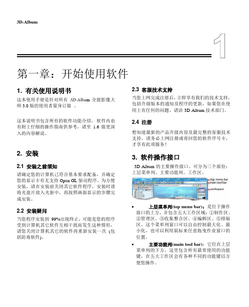
3D-Album第一章:开始使用软件1. 有关使用说明书这本使用手册是针对所有3D-Albu m全能影像大师3.0版的使用者量身订做。
这本说明书包含所有的软件功能介绍,软件内也有附上仔细的操作指南供参考,请至1.6做更深入的内容解说。
2. 安装2.1 安装之前须知请确定您的计算机己符合基本要求配备,并确定您的显示卡有无支持Open GL驱动程序,为方便安装,请在安装前关闭其它软件程序,安装时请将光盘片放入光驱中,再按照画面显示的步骤完成安装。
2.2 安装疑问当您程序安装到99%出现终止,可能是您的程序受到计算机其它软件互相干扰而发生这种情形,请您关闭计算机其它的软件再重新安装一次(包括防毒软件)。
2.3 客服技术支持当您上网完成注册后,立即享有我们的技术支持,包括升级版本的通知及程序的更新,如果您在使用上有任何的问题,请洽3D-Album技术部门。
2.4 注册想知道最新的产品升级内容及最完整的客服技术支持,请务必上网注册或寄回您的软件序号卡,才享有此项服务!3. 软件操作接口3D-Album的主要操作接口,可分为三个部份:上层菜单列、主要功能列、工作区。
∙上层菜单列(top menu bar):是位于操作接口的上方,并包含五大工作区域:①制作区、②管理区、③收集整合区、④编辑区、⑤排版区。
这个菜单列窗口可以自由控制最大化、最小化,也可以利用鼠标来任意拖曳作业窗口的位置。
∙主要功能列(main tool bar):它位在上层菜单列的下方,这里包含所有最常使用的功能键,在五大工作区会有各种不同的功能键以方便您操作。
工作区(workspace):能提供给您非常简单明了的工作环境。
4. 开始操作软件当您需要开启计算机中资料夹的相片时,您不需要在软件外的窗口来开启,您可以直接在3D-Album 的制作区来开启您的相片,再利用几个简单的步骤来制作您个人独一无二的写真相片。
步骤 1 选择相片资料夹请点选位于屏幕右上方 的 您可到3D-Album 档案总管中来选择您下个步骤要使用的相片资料夹,在确定选择的资料夹后,您所选择的相片缩图将会出现在窗口右边,您可以再以拖曳的方式来调整相片的播放顺序。
视觉定位助手软件介绍
视觉定位助手软件介绍步骤1、使用该软件需要先安装SetupAutoVISION ,在目录里可以找到。
步骤2、将文件夹“视觉定位助手”拷贝到电脑磁盘上,再把该文件夹里面的“视觉定位助手.exe ”发送快捷方式到桌面上。
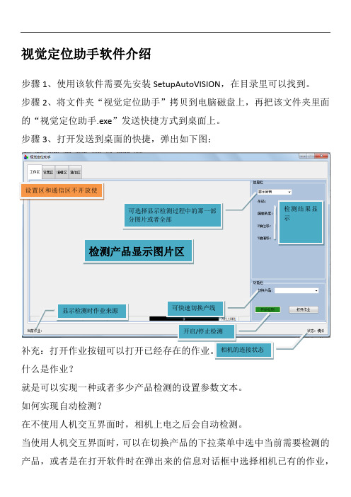
步骤3、打开发送到桌面的快捷,弹出如下图:什么是作业?就是可以实现一种或者多少产品检测的设置参数文本。
如何实现自动检测?在不使用人机交互界面时,相机上电之后会自动检测。
当使用人机交互界面时,可以在切换产品的下拉菜单中选中当前需要检测的产品,或者是在打开软件时在弹出来的信息对话框中选择相机已有的作业,检测产品显示图片区显示检测时作业来源可选择显示检测过程中的那一部分图片或者全部检测结果显示设置区和通信区不开放使或者使用打开作业按钮选择电脑里的作业文本。
当选择一种作业之后,在界面左下角会显现作业的来源。
然后点击开始检测即可,自动检测。
如何转化坐标系(又叫9点标定)? 步骤1、选择一种作业。
步骤2、将窗口切换到 编辑区->相机功能->普通编辑->转化坐标系。
如下图9点标定就是将对应的点坐标填充到对应的Vision Locations 里面。
上图的示意图为Motion Position 的形象图。
如当选中下拉菜单中的point5就是对应的是(0,0),而对应获得的坐标值将被写到Vision Locations 的中间输入框。
如何生成新的标定文件?步骤1、先确定一个最小的单位距离10(推荐为10mm )Y 轴X 轴可获取坐标,需要单击两次(-5,5) (0,5) (5,5)(-5,0) (0,0) (5,0)(-5,-5) (0,-5) (5,-5)示意图步骤2、将最小的单位距离填入到Vision Locations 里面的带星号的方框如上图的()这里,然后双击该方框则Motion Position 里的数据都变成如下图所示:步骤3、用机械手把检测品移动到视野的基本中心位置。
视觉自动点胶机软件说明书
视觉自动点胶机软件说明书目录注意事项: (03)软件说明: (03)第一章:软件安装 (04)第二章:软件简介 (11)第三章:文件操作 (13)第四章:编程操作 (14)第五章:编程方法(双Mark点) (22)第六章:参数设置 (35)第七章:图像 (44)第八章:测试 (51)第九章:生产 (53)第十章:系统 (57)附:维护保养 (59)附:常见问题 (59)注意事项●请保管好光盘内的所有资料,建议用户将光盘内的资料拷贝到电脑里,以防丢失。
●本软件的启动需要USB密钥支持,建议将USB密钥插入电脑机箱后USB接口。
●请保管好USB密钥。
若USB密钥丢失,用户需重新购买。
●本书只提供软件的使用方法,硬件及其电气恕不作说明。
●因用户使用、操作不当造成机器损坏的,本公司既不负相关责任。
●使用前应把电脑系统时间调为当前正确时间,以便软件数据时间能正确显示和记录。
●电脑为机器专用,请勿在本软件使用时开启其它应用程序,以免影响本软件工作。
●请勿将有木马、病毒的U盘插入电脑,某些电脑病毒可能会影响软件的正常使用。
电脑最好装杀毒软件,并定时杀毒。
●请爱护、保养好机器,机器定期保养可维持其最佳性能。
●由于软件版本升级等原因,说明书与软件实际操作可能会有出入,请以软件最新版操作为准。
软件信息:●名称:视觉自动点胶机/Vision Dispenser●版本:4.370●安装包大小:约120MB●支持语言:简体中文/英文(美国)●支持系统●支持机型:在线式/落地式/桌面式/桌面式双Y轴/带旋转轴机器●支持胶阀:普通胶阀/喷射阀/AB胶双液阀●支持相机:德鸿/堡盟(Baumer)/巴斯勒(Basler)●支持运动控制卡:固高GT/固高GTS/运动控制器●支持光源控制器:华周(HZ)/菲视特(FST)/奥普特(OPT)●支持运动轨迹类型:单点/直线/圆弧/圆形/三维直线/三维圆弧/连续轨迹插补/四轴联动●支持Mark点类型:单Mark点/双Mark点/多Mark点●支持Mark识别方式:圆/矩形/椭圆/三角形/圆环/直角/任意形状●支持导入文件类型:CAD文件(dxf格式)/贴片机文件(Pick & Place)●支持扩展外接设备:测高仪/扫码枪/电子称/自动对针●支持扩展外接通讯:IO通讯/串口通讯/网络通讯/文件共享●最多支持控制轴数:6●最多支持控制IO数:24路输入、24路输出。
CCD视觉检测软件操作说明书(In-Vision 6.2版本)

工业检测、CCD检测In-Vision6.2视觉检测软件操作说明书功能:1、产品的二维、三维尺寸测量;2、颜色的识别、线材等安装次序的检测;3、字符、条码、二维码的识别;4、金属、塑胶、印刷品、药品、玻璃等表面缺陷检测;5、配合自动化非标设备检测、定位,机器人定位;6、自带影像二次元测量软件。
CCD检测软件In-Vision6.2操作说明目录1软件安装 (1)1.1安装In-Vision6.2软件 (1)1.2安装相机驱动 (2)1.3安装加密狗驱动 (2)1.4安装IO卡驱动 (2)1.5安装串口组件 (3)1.6安装VS2008最小库 (4)1.7安装IO信号管理工具 (4)2软件使用 (5)2.1软件启动 (5)2.2连接相机 (8)2.3界面介绍 (10)2.3.1菜单 (10)2.3.2工具栏 (13)2.3.3任务导航栏 (13)2.3.4相机视图显示栏 (15)2.3.5检测设置和规则设置栏 (16)2.3.6规则设置预览和检测结果预览 (17)2.3.7状态栏 (17)2.3.8鼠标操作 (18)2.4功能介绍及操作流程 (18)2.4.1绘制检测区域 (18)2.4.2设置检测区域定位位置 (20)2.4.3辅助相机聚焦 (22)2.4.4检测规则设置 (22)2.4.5动态跟踪 (40)2.2.6相机标定 (41)2.2.7自定义IO (43)2.2.8结果输出 (43)2.2.9颜色识别 (44)2.2.10目标定位 (45)2.2.11表面缺陷检测 (46)2.2.12影像二次元 (47)2.4部分案例 (48)3关于我们 (54)1软件安装 (55)1.1安装软件 (55)1.2安装相机驱动 (55)1.3安装加密狗驱动 (55)2软件使用 (56)2.1界面介绍 (56)2.1.1菜单 (56)2.1.2工具栏 (58)2.1.3状态栏 (58)2.2功能介绍 (58)2.2.1载入数据 (58)2.2.2相机标定 (59)2.2.3直线距离测量 (59)2.2.4圆测量 (61)2.2.5角度测量 (62)2.2.6修改测量 (63)2.2.7自动捕捉 (63)2.2.8保存测量 (63)1软件安装1.1安装In-Vision6.2软件右键查看属性双击图标进行安装界面默认下一步安装完In-Vision软件1.2安装相机驱动()然后下一步自动安装相机驱动:1.3安装加密狗驱动然后下一步自动安装加密狗驱动:1.4安装IO卡驱动然后下一步自动安装IO卡驱动:1.5安装串口组件1.6安装VS2008最小库1.7安装IO信号管理工具注:整个安装过程一次完成,自动安装所有驱动程序。
PALLAS BOX 系列智能视觉系统应用说明书

PALLAS BOX系列智能视觉系统应用说明书版本:V1.0.1发布日期:2021-06-09本手册中所提及的其它软硬件产品的商标与名称,都属于相应公司所有。
本手册的版权属于中国大恒(集团)有限公司北京图像视觉技术分公司所有。
未得到本公司的正式许可,任何组织或个人均不得以任何手段和形式对本手册内容进行复制或传播。
本手册的内容若有任何修改,恕不另行通知。
© 2021中国大恒(集团)有限公司北京图像视觉技术分公司版权所有网站:公司总机:************客户服务热线:400-999-7595销售信箱:************************支持信箱:**************************首先感谢您选用大恒图像产品,PALLAS BOX系列是一款面向于自动化、机器视觉等行业的高性能书本式嵌入式智能视觉系统,集PoE技术、光源控制器、IO卡为一体,使其成为高计算能力、高实时性以及多功能性的完美视觉系统平台。
扩展功能板提供4个独立的Intel i210-AT PoE千兆网口;4路光源PWM 控制接口;4路光源外部触发信号输入;16路隔离DI/DO可供用户进行功能自定义。
广泛应用于3C制造、制药、包装、机械检测设备、模具监视器、机器人、运动控制、智慧交通等多种行业和领域。
本手册详细介绍了PALLAS BOX系列智能视觉系统的应用,对产品的功能描述和相关设置进行说明。
1. 概述 (1)1.1. 参考文档 (1)1.2. 安全须知 (1)2. PALLAS BOX系列产品介绍 (2)2.1. 产品特点 (2)2.2. 产品规格 (3)2.3. 产品尺寸 (4)2.4. 产品接口定义 (5)2.4.1. POE网口:LAN3,LAN4,LAN5,LAN6 (5)2.4.2. 接线端子 (6)2.4.2.1. DI (7)2.4.2.2. DO (9)2.4.2.3. PWM光源输出 (9)2.4.2.4. 光源外部硬触发 (9)3. BIOS设置 (11)3.1. 本章简介 (11)3.2. 启动BIOS设置 (11)3.3. BIOS设置方法 (11)3.4. BIOS设定项 (12)3.4.1. BIOS主界面 (12)3.4.2. Main (13)3.4.3. Advanced (13)3.4.3.1. CPU Configuration (15)3.4.3.2. ACPI Settings (16)3.4.3.3. SATA Configuration (16)3.4.3.4. Display Configuration (17)3.4.3.5. AC Power Loss (18)3.4.3.6. Wake up setting (19)3.4.3.7. Watch Dog Configuration (20)3.4.3.8. Super IO Configuration (21)3.4.3.8.1. Serial Port x Configuration (22)3.4.3.9. Hardware Monitor (23)3.4.3.10. USB Configuration (23)3.4.3.11. CSM Configuration (24)3.4.4. Chipset (26)3.4.4.1. System Agent Configuration (26)3.4.4.1.1. Memory Configuration (27)3.4.4.2. PCH-IO Configuration (28)3.4.4.2.1. PCI Express Configuration (28)3.4.4.2.2. LAN Configuration (29)3.4.4.2.3. USB Configuration (30)3.4.5. Security (31)3.4.6. Boot (31)3.4.7. Save & Exit (32)4. 系统安装 (34)4.1. 硬件安装 (34)4.1.1. SSD和Wi-Fi模块的安装 (34)4.1.2. 风扇的安装 (34)4.1.3. 安装挂板的安装 (35)4.2. 驱动安装 (36)5. 安全预防与维护 (37)5.1. 安全预防措施 (37)5.1.1. 通用安全预防措施 (37)5.1.2. 防静电预防措施 (37)5.1.3. 产品处置方式 (38)5.2. 维护与清洁预防措施 (38)5.2.1. 维护与清洁 (38)5.2.2. 清洁工具 (38)6. 版本说明 (39)7. 联系方式 (40)7.1. 销售联系方式 (40)7.2. 技术支持联系方式 (40)1.概述1. 概述1.1. 参考文档有关该产品的文档资料见如下列表,请在使用该产品之前对其进行阅读。
视觉软件操作手册

视觉软件操作手册
视觉软件使用手册(Version 1.0)
目录
第一章总述 ........................................................ 错误!未定义书签。
第二章配置相机环境 ......................................... 错误!未定义书签。
第三章进入主界面............................................. 错误!未定义书签。
第四章图像处理流程 . (8)
第五章脚本变量设置 ......................................... 错误!未定义书签。
第六章状态机设置 (13)
第七章信息栏查看............................................. 错误!未定义书签。
第一章总述
该视觉软件是经过摄像装置进行图像处理计算,实现对各个行业不同产品高精度定位、检测等,
本文档为软件使用基本操作手册,主要介绍该软件基本操作和具体处理流程的概况以及常见问题的解决方法。
第二章选择相机环境
相机设置好IP后,启动软件
选择已连接的相机。
- 1、下载文档前请自行甄别文档内容的完整性,平台不提供额外的编辑、内容补充、找答案等附加服务。
- 2、"仅部分预览"的文档,不可在线预览部分如存在完整性等问题,可反馈申请退款(可完整预览的文档不适用该条件!)。
- 3、如文档侵犯您的权益,请联系客服反馈,我们会尽快为您处理(人工客服工作时间:9:00-18:30)。
视觉联机激光控制软件-使用说明书-深圳市智远数控有限公司目录上层软件使用操作说明第一章驱动和软件的安装 (2)1.1 数控系统软件简介 (3)1.2 控制系统的组成 (3)1.3 驱动和软件的安装 (3)1.3.1视觉驱动MIL的安装与卸载 (4)1.3.2视觉切割软件的安装 (10)1.4软件特点 (13)1.5单反相机应用步骤 (14)1.6界面说明 (15)第二章设备参数的设置 (17)第三章工作面板 (21)3.1 图层管理 (21)3.2 手动控制 (23)3.2.1标定管理 (24)3.2.2 模版切割设置 (29)3.2.3 寻边切割设置 (38)3.2.4寻边切割功能对材料要求 (40)3.3设备控制 (40)3.4加工信息 (41)底层软件/硬件使用说明及接线 (42)第一章概述 (42)1.1 系统功能 (42)第二章安装接线说明 (43)2.1 安装尺寸 (43)2.2 接线说明 (44)2.21 接口板 (44)2.22 接线图 (44)2.3 端口定义说明 (47)2.32 U盘接口 (48)2.33 PC接口 (48)2.34 网络接口 (48)2.35 端口定义 (48)第三章常见问题排除 (51)3.1 电脑连接问题 (51)3.2 U盘读写问题 (51)3.3 相机连接问题 (51)3.4 问题现象: (51)3.5 机器不动作 (52)第四章经典激光切割机接线图 (53)4.1 标准激光切割机接线图 (53)第一章驱动和软件的安装1.1 数控系统软件简介PowerCut视觉激光切割控制软件是深圳市智远数控有限公司集多年行业经验、业内知名研发团队精心打造的一款激光切割数控精品。
该软件简单易学、运动控制算法成熟稳定、切割工艺完备、人机交互界面友好,适用于服装、亚克力、家俱等非金属激光切割控制。
1.2 控制系统的组成控制系统由硬件(运动控制卡及配件)和软件两部分组成。
软件的目录及文件说明:表1.1.1.1软件的目录及文件说明硬件设备组成:表1.1.1.2硬件设备组成1.3 驱动和软件的安装安装环境:硬件要求:CPU主频2.1G以上、内存1G以上、硬盘100G以上软件要求: Microsoft Windows操作系统(WinXP、WIN7)安装顺序:➢视觉驱动的安装➢视觉软件的安装1.3.1视觉驱动MIL的安装与卸载将视觉驱动打开后有两个文件夹为卸载文件夹视觉驱动安装文件夹的内容显示如下图所示:➢MIL的安装用鼠标双击该安装文件夹,安装前请更改兼容性,将鼠标移上点鼠标右键点属性弹出对话框选兼容性方法如下图所示:双击图标,进入安装界面,如下图所示:图1.1.2.4.2 安装界面1 点击Next,进行下一步:图1.1.2.4.3 安装界面2 点击Next,进行下一步:安装界面4请点击I AGREE,安装完成后程序将提示是否需要重启电脑,如下所示:安装界面5点击Finish,完成Matrox Imaging mini的安装,重启电脑后请更改下硬件加速用鼠标点电脑右下角开始按键如下图所示:点击该键弹出对话框用鼠标点击进行更改移动滑块一般移动到4-6之间即可完成后点OK如下图所示:➢MIL的卸载:在第一次安装视觉驱动失败,需要对视觉驱动进行卸载后重新安装视觉驱动,请用鼠标双击弹出对话框如下图卸载点确定不卸载点取消,卸载完成后电脑系统会重启,请重新安装视觉驱动。
1.3.2视觉切割软件的安装安装PowerCut视觉切割软件,双击文件夹,打开文件夹如下图文件:双击安装包,进入安装界面连续单击“下一步”完成安装.选择合适的语言点下一步完成安装。
安装完成后会在桌面上生成一个快捷打开方式图标请用鼠标右键单击快捷方式打开图标,弹出对话框请用鼠标点击,在兼容模式里选择winXP进行兼容,否则软件无法打开。
如下图。
1.4软件特点➢大幅面自动识别功能➢自动寻边切割功能➢界面友好,易学、操作简便。
➢兼容AI、BMP、PLT、DXF、DST等多种图形图像数据格式。
➢可制作简单的图形、文字并对导入的数据进行编辑和排版。
➢能多级分层加工和定义输出顺序。
➢加工过程和精度个性化设置,激光头运行轨迹仿真显示。
➢多种路径优化功能,加工过程中暂停功能。
➢图形与加工参数的多种保存方式及其重复利用。
➢独特的双激光系统间歇工作与各自独立工作及运动轨迹补偿控制功能。
➢根据加工的不同需求可自行设定加工起始点、工作路径、激光头停靠位置等。
➢兼容多种通讯方式,用户可根据实际的情况采用USB端口通讯或网络通讯。
➢ 加工过程中实时调速功能。
➢ 断电保护功能,加工过程中突然断电,系统能记住该断点,恢复供电后能迅速找到该断点继续加工1.5单反相机应用步骤1.打开相机开关,拨到“ON ”处,拍照模式拨到“P ”档。
(P 档:程序自动曝光)如下图.2.在相机镜头上找到AF (自动对焦),MF (手动对焦)和STABILIZER(防抖开关),镜头先拨到“AF ”自动对焦档,防抖开关打开“ON ”.如下图:3.打开视觉软件,点击按钮,弹出相机对画框,再手动旋转相机镜头同时观察相机对画框拍摄的范围是否和设备幅面相符合。
相机开关程序自动曝光 自动对焦防抖开关4.相机拍摄的范围和设备幅面相符合后,点击按钮,弹出对画框,再点击按钮,这时相机镜头会自动旋转完成自动对焦,待拍照完成后观察图片清晰度,如满足要求,就把相机镜头拨到“MF ”手动对焦档上。
1.6界面说明➢ 框选匹配有效区:框选:点击框选按钮,在整个幅面上框选要匹配的某块有效区。
软件只匹配框选区域内的图形。
如图,绿色区域内。
标准工具 菜单栏 图形修改工具图形创建工具栏 图形编辑图层工具 控制面 框选 手动对焦撤销有效区:点击框选键,框选整个设备幅面,点击左键撤销有效区。
如图,绿色框。
第二章设备参数的设置2.1设备参数选项卡:设备控制:➢机器幅面X:是指工作台X轴移动范围,即激光头横向移动的最大范围(mm)。
➢机器幅面Y:是指工作台Y轴移动范围,即激光头纵向移动的最大范围(mm)。
➢机器幅面Z:是指工作台Z轴移动范围,主要用于左右推板机器,Z轴范围是有效推板长度减去X轴幅面(以X轴为例,单位mm),连续送料机器不受此参数限制。
➢X轴脉冲当量:相对于每一脉冲信号机床运动部件的位移量称为脉冲当量,又称作最小设定单位。
点击设置脉冲当量,如图。
计算脉冲当量有两种方式:理论计算和实践计算。
A、理论计算:电机一圈脉冲数量:步进电机;以1.8度、32细分驱动机器为例,电机一圈脉冲数量:360/1.8*32=6400(个脉冲)。
伺服电机;以松下伺服A5为例,PR008参数默认上位机发送一万个脉冲电机转一圈。
电机一圈实走长度:机械设计时此值已经确定,询问机械设计部门。
点击,自动计算脉冲当量,点击将该值设置到X轴脉冲当量。
B、实践计算:理论长度:画一条100mm水平直线,理论长度为100mm,生成加工文件切割。
真实长度:用测量工具测得的实际切割长度,假如为50mm。
点击,自动计算脉冲当量,点击将该值设置到X轴脉冲当量。
➢Y轴脉冲当量:同X轴脉冲当量计算方法。
➢Z轴脉冲当量:同X轴脉冲当量计算方法。
➢点射功率:设置预调(点射)功率百分比。
➢点射时间:设置预调(点射)出光时间。
➢预激一:设置激光管一预激励功率百分比。
➢预激二:设置激光管二预激励功率百分比。
➢最大功率:设置激光最大功率百分比。
➢PWM频率:设置PWM波频率,请根据激光器特性设置。
➢回零速度:设置回原点速度。
➢回零轴:设置回零轴。
➢读设备参数:读取控制器内设置的参数。
加工设置:➢移动速度(快):设置手动移动时的速度。
➢坐标系:选择坐标系(原点开关位置,左上或右上)。
➢启动速度:设置电机启动速度。
➢曲线速率:设置曲线的速度倍率,该值越大,切割曲线速度越快,反之越慢。
➢空程速度:设置机床空跑路径速度。
➢空程加速度:设置机床空跑路径加速度。
➢X轴拐角速度:设置X轴过拐角时的速度。
➢Y轴拐角速度:设置Y轴过拐角时的速度。
➢Z轴速度:设置Z轴移动速度。
➢Z轴加速度:设置Z轴移动时的加速度。
➢保护控制:在加工时检测保护控制信号。
➢应用:点击该命令,将设置好的参数下传给控制器(必须连接控制器,否则提示通信故障)。
2.2 帮助菜单项单击菜单栏图标打开帮助下拉菜单选择,弹出注册/升级窗口,显示注册/升级信息。
➢注册方法:原注册码过期后从厂商处获取新注册码,将新的十六位注册码输入方框后,点击注册。
➢升级方法:从厂商处获取升级文件,保存到计算机自己指定的位置,升级时点击,找到存放在指定位置的升级文件点击。
2.3 设备连接单击按钮,出现设备连接对话框,如下图:➢设备列表:列出可联接的设备,包括类型、设备名称、地址、状态等信息。
将高亮条移到相应条目上双击或单击按钮,连接该设备。
将高亮条移到相应条目上单击按钮,断开该设备连接点击按钮,刷新设备连接页面。
第三章工作面板工作面板包括备选设备、图层管理、设备控制及手动控制等内容。
工作面板选项卡可以通过单击右侧定风钉进行固定或自动隐藏红色框内为工作面板。
3.1 图层管理图层管理包括图层颜色、加工模式、速度、功率、是否输出等信息及单击图层时点击鼠标右键会有提示框弹出上移、下移、顶端、底端、选中等操作命令按钮。
➢单击某一颜色图层,该层信息高亮显示,单击按钮,该图层上移一层;单击按钮,该图层下移一层;单击按钮,该图层上移到最顶端;单击按钮,该图层下移到最底端;单击按钮,该颜色图层对象被选中。
提示:文件加工顺序以图层排列顺序为依据,改变图层排列顺序即改变加工顺序。
➢双击某一颜色图层,打开层信息设置框,如下图:层信息设置框左侧显示所有图层及顺序,右侧显示当前图层相关信息。
➢当前层颜色:显示所选当前层颜色,鼠标单击左侧不同图层,当前层相应改变。
➢工作模式:,如下图所示:输出:勾选输出,生成激光加工文件时输出该图层对象。
不勾选输出,该图层对象不输出,加工过程中该图层对象不加工。
➢切割参数设置:●加工速度:加工图形对象的速度。
●加工加速度:加工过程中,出激光时,激光头运行的最大加速度。
●激光能量1:加工时激光管一最高速度对应的激光功率百分比。
●拐角激光能量1:加工时激光管一拐角速度对应的激光功率百分比。
点击按钮,确认层信息设置。
点击按钮,退出层信息设置。
3.2 手动控制➢、:点击该按钮控制X轴正、反向移动。
➢、:点击该按钮控制Y轴正、反向移动。
➢Z+、Z-:点击该按钮控制Z轴正、反向移动。
➢精确移动:在此输入数值再按方向键,激光头在该方向精确移动。
➢设起点,回起点:当前位置就是以激光头所在的位置为起点,用户设置是要自己设定一个加工起点的在把激光头移到你所要的最佳的加工起点位置然后点,在加工完成后激光头都会回到加工起点,就是回到加工起点。