LU192系列电力监测仪说明书_V1.1(不适用H尺寸)
IDI2015C 单相电参数综合测量仪 用户手册说明书

IDI2015C单相电参数综合测量仪用 户 手 册青岛仪迪电子有限公司QINGDAO IDI ELECTRONICS CO.,LTD.02000083号检定规程:JJG(航天)34—1999中国航天工业总公司交流数字电压表检定规程 JJG(航天)35—1999中国航天工业总公司交流数字电流表检定规程JJG780—1992国家交流数字功率表检定规程执行标准:Q/02YDY006—2005 MD20A单相电参数综合测量仪企业标准目 录前 言 (1)第一章 安全规则1.1 一般规定 (2)1.2 维护和保养 (2)第二章 使用安装2.1 包装拆封 (3)2.2 包装箱中的内容 (3)2.3 测量仪电源电压 (3)2.4 测量仪的初步检查 (3)第三章 产品概述及技术指标3.1 产品分类 (4)3.2 整机规格 (4)3.3 技术指标 (5)3.4 测量范围 (5)第四章 测量仪面板说明4.1 单相电参数综合测量仪前面板示图及说明 (7)4.2 单相电能量综合测量仪前面板示图及说明 (8)第五章 使用说明5.1 测量仪的测量接线图 (11)5.2 后面板说明 (11)5.3 被测负载的连接 (11)5.4 测量仪的开机 (11)5.5 被测负载电源连接 (11)5.6合上负载电源的开关 (12)5.7 接通被测负载的电源开关 (12)5.8 结果处理 (12)5.9自动报警功能 (12)5.10数据锁存功能 (14)5.11 串行通讯功能 (14)第六章 维护指南6.1 测量仪日常维护 (16)6.2常见故障及排除 (16)6.3品质保证 (16)附录1:测量仪的检定方法 (17)附录2:输入输出配线要求 (19)本说明仅适用常规产品,如有技术改进,恕不另行通知专业品质唯一坚持前 言IDI2015C单相电参数综合测量仪是仪迪电子公司电参数综合测量仪的换代产品,该系列产品以16位单片机技术为核心,内部采用超大规模集成电路,使体积进一步减少,故障点大幅度降低,在工艺上做到精密、细致,使用上做到安全、方便、简捷,在同行业中处于领先地位。
使用说明书

使用说明书感谢您选购中创电测电力线网络分析仪,本仪器基于中创电测的高科技设计理念和高标准要求,为您提供高品质和高性能的现场使用体验。
本使用说明书专门用于帮助您了解设备的用途、功能以及特性。
请先阅读说明文件●适应设备之前,请先仔细阅读全部安全注意事项和本说明书,以确保安全和正确使用。
●本说明书中的说明基于设备的默认设置。
●本说明书中所用的图像和屏幕截图可能与实际产品的外观略有差异。
●本说明书中的内容可能与产品略有差异,如有变更,恕不另行通知。
●请访问公司网站,获取说明书的最新版本。
●可用功能和附加服务可能因国家、地区或者硬件规格而异。
●请妥善保存本说明书以供日后参考。
目录/CONTENTS前言 (3)1产品概览 (4)2产品说明 (4)3产品功能 (5)4使用入门 (7)5安全信息 (11)6质量保证及售后服务 (13)7有毒有害物质表 (14)前言在低压配电的营业管理中,台区线超标一直以来都是让人头痛的问题,在实际工作中,没有合适手段解决线损超标,只能采用“拉闸验电”的方式进行核查。
从核查结果看,除窃电外,多数原因是用户电表档案错误造成的。
电表档案错误以及变压器供电线路混乱已经成了一个久治不绝的问题。
自远程自动抄表技术出现后,电力线载波通讯方案被大面积推广,抄表员不再走街串巷抄表,省时省力;好处明显但问题暴露的也很突出,除了部分台区线损依旧偏大外,很多台区的抄表成功率也达不到验收标准,电表档案错误导致线损超标的问题依旧无法解决。
由此看出,在营销管理中电表档案准确性是何等重要。
为解决电表档案准确性问题,国内很多公司开始研制相应解决方案。
台区识别仪是此类问题解决方案的代表,基本的实现方式是结合电流钳,采用截波扩频调制技术,这种实现方式从根本上不能解决电表档案准确性的问题,原因为高频调制的截波信号能够通过高压线、电缆、地线串扰到其它变压器,不能保证通讯信号的跨台区传输问题。
使用这种方案的识别仪来解决档案问题,其结果可想而知。
胜利仪器 VICTOR 7200A漏电开关测试仪说明书

目录一、安全规则及注意事项 (1)二、简介 (2)三、量程及精度 (2)四、技术规格 (3)五、仪表结构 (5)六、操作方法 (6)6.1、电池电压检查 (6)6.2、电压测试 (6)6.3、操作说明 (6)6.4、漏电开关测试接线方法 (7)6.5背光控制 (8)6.6、数据锁定/存储 (8)6.7、数据查阅/删除 (8)七、装箱单 (9)一、安全规则及注意事项感谢您购买了本公司漏电开关测试仪,在你初次使用该仪器前,为避免发生可能的触电或人身伤害,请一定:详细阅读并严格遵守本手册所列出的安全规则及注意事项。
✧任何情况下,使用本仪表应特别注意安全。
✧测量时,移动电话等高频信号发生器请勿在仪表旁使用,以免引起误差。
✧注意本仪表机身的标贴文字及符号。
✧使用前应确认仪表及附件完好,仪表、测试线绝缘层无破损、无裸露、无断线才能使用。
✧测量过程中,严禁接触裸露导体及正在测量的回路。
✧确认导线的连接插头已紧密地插入仪表接口内。
✧请勿在易燃性场所测量,火花可能引起爆炸。
✧仪表在使用中,机壳或测试线发生断裂而造成金属外露时,请停止使用。
✧请勿于高温潮湿,有结露的场所及日光直射下长时间放置和存放仪表。
✧给仪表更换电池时,请确认测试线已移离仪表,仪表处于关机状态。
✧仪表显示电池电压低符号“”,应及时充电或者更换电池。
✧电池盖打开时,及打雷时,请勿进行测量。
✧注意本仪表所规定的测量范围及使用环境。
✧使用、拆卸、校准、维修本仪表,必须由有授权资格的人员操作。
✧由于本仪表原因,继续使用会带来危险时,应立即停止使用,并马上封存,由有授权资格的机构处理。
✧”安全警告标志,使用者必须严格依照本手册内容进行安全操作。
二、简介VICTOR7200A漏电开关测试仪,又叫漏电开关检测仪、漏电保护器测试仪、剩余电流动作保护器检测仪、剩余电流动作保护器测试仪、是工程质量监督站和建筑公司必备的检测仪器,可以测量漏电开关的动作时间和动作电流。
洛雷克L19LD800系列监控系统说明书

infOrMatiOn in tHis dOcuMent is suBject tO cHange witHOut nOtice. as Our prOducts are suBject tO cOntinuOus iMprOveMent, L19LD800 SeriesW W W.L O R E X C C T V.C O MQuick start guide r2PACKAGE CONTENTS ANDINSTALLATION GUIDE:☠ System Contents:1 - 19” 8 Channel LCD Monitor with pre-installed HDD *4 - High Res. Color Cameras *4 - 100 ft (30M) Extension Cables *4 - Camera Stands with Mounting Screws *1 - 10 ft Ethernet Cable Intermediateeasyunder 30 minutes under 60 minutes HardwareHi Speedover 60 minutesTimeunder 30 minutes under 15 minutes under 60 minutes Hand Tools Hardware Skills - IntermediateTimeSTEP 3Skill LevelTimeunder 30 minutes under 15 minutes under 60 minutesHand Tools HardwareRouterTimeSkills - Advanced* Installation time may vary based on applicationdevice cOnnectiOns (stand removed)2ascrews2the system has an efficient back panel control that provides a cable management solution.By design the connectors are not easily accessible, in order to secure the connections.it is recommended to remove the stand for initial set-up by simpy unscrewing four screws with a standard screw driver.OPTIONAL - REMOVE MONITOR STANDtilt the monitor (40˚) to allow for easier access to the connectors.TILT MONITOR13your system includes 4 high resolution 6 pin din cameras.CONNECT CAMERAS TO THE MONITORconnect one end of the ethernet cable to one of the router’s (notincluded) Lan pOrts and the other end to the Monitor’s network portlocated at the bottom of the monitor. see picture below showing ageneric Lan/wan connection.CONNECT ETHERNET CABLE4connect one end of the power adaptor to the monitor, the other endto an electrical outlet. this unit powers On once it is plugged in to thepower outlet.tip: Once you are done with the connections, remember to screw thestand back on.CONNECT POWER CABLE5WAN (WIDEAREA NETWORK)LAN (LOCAL AREA NETWORK)TO YOUR COMPUTERTO YOUR MONITORBACK OF THE ROUTER SHOWN6CONTINUEDtip: test the cameras prior to selectinga permanent mounting location bytemporarily connecting the camerasand cables to your system.* connect cameras to extension cablesby aligning the arrows. plug in camerasand cables before mounting the cameras.nOte: the arrow mark on top of the flat side ofthe camera and cable connectors should faceup while inserting to the Monitor.connect the first camera to the cH1 input. follow the same steps toconnect the additional cameras.4aUNIvERSAL DIN TO BNC CABLECONTINUEDthe unit will automatically begin loading when power is connected to the system.INITIAL LOADING SEQUENCEcb7aclick the Menu button on the front panel of the Monitor (or the remote controller) to enter the Main Menu. from the Main Menu move to systeM and press the enter button to go to the date/tiMe menu to activate menu options.SET THE DATE & TIME9Congratulations! You have completed Step 1 successfully. You can now view, record and Make sure that the Date and Time are set prior to recording.• Menu Button – accesses the setup menu, and returns to previous menu options.• navigation controls - Move up/down/Left/right.• enter Button - press this button to select and change the values in a menu option.nOte: after you see all four (4) camera images on your monitor screen, remove the protective film from camera(s) and monitor screen.a. during the loading sequence, the system will perform a Hard drive and firmware check and the screen will display the text message “systeM cHeck”.b. Once the system checks are completed, the screen will display the text message “initiaLiZing systeM” before completing the loading process.c. the unit will initially load to a split screen view, displaying all 8 cameras (if available) and a system legend in a 3x3 screen view.MENU NAVIGATION CONTROLS8MenunOte: this may take up to 60 seconds. please wait until the system completes loading.STEP 2 - SET UP LOCAL VIEWING ON YOUR PCnOte: the system will lease networking information from your router. if you wish to set your information manually, then set the dHcp MOde to ManuaL. please consult your Hardware Manual for further Menu options.1insert the Lorex client 3.0 software cd into your local computer’s cd rOM drive and proceed with the installation.INSTALL SOFTWARE(on your local computer)computer - not includedtHis step reLates tO reMOte viewing Over tHe Lan (LOcaL area netwOrk) By using a pc LOcated On tHe saMe netwOrk as tHat Of tHe systeM.2STEP 2 - SET UP LOCAL VIEWING ON YOUR PCCONTINUEDfollow the installation screens to complete Lorex client 3.0 software installation.LOREX CLIENT 3.0 SOFTWARE34LorexClientLorexPlayerclick the Menu button and select the new item.ADD A LOCAL SITE:(on your local computer)5tip: when you run Lorexclient on windows xp operating system, you will see the windows security alert. please click unblock to run the application.please refer to your Lorex client 3.0 software Manual for instructions about using Lorex Backup player and storage calculator.STEP 2 - SET UP LOCAL VIEWING ON YOUR PCCONTINUEDenter a name and site information for the remote site. 1. enter a name of the site (e.g. Office)2. enter the user id (admin by default)3. enter the user password (blank by default)4. enter the dvr/Monitor tcp/ip port (3000 by default)5. enter the ip address recorded in step 2-16. click add to add the remote site7. click exitENTER SETUP INFORMATION(on your local computer)6781234567OfficeSTEP 3 - SET UP INTERNET REMOTE MONITORINGPORT FORWARD YOUR ROUTER1port forward your router first before proceeding with the set-up (ports 80, 3000, 3001, 3002, 3003).all routers are different. to port forward your router, please refer to your router’s user manual.a router configuration guide is available on your Lorex client software cd and also on /support in the consumer’s guide section.CREATE ACCOUNTfrom the website, click the create accOunt option.3router - not included2STEP 3 - SET UP INTERNET REMOTE MONITORING CONTINUEDCOMPLETE NEW ACCOUNT INFORMATION41. fOr prOduct License select the L19Ld800 series option from the drop down menu.2. fOr prOduct cOde enter the Monitor’s Mac address (recorded in step 2-1).3. fOr urL reQuest enter a unique urL name (e.g. myurl). nOte: urL name should not be more than 15 characters.123REGISTRATION EMAILan automated registratiOn cOnfirMatiOn eMaiL will be sent to your email. print and save this confirmation. you will need this information to access your system remotely.5Service Provider: Domain Name: User ID: tomsmith1Password: (your password)ENTER DDNS SET-UP ON YOUR MONITOROnce the ddns settings have been configured online, the information must be entered on the system toallow for remote connection via the Lorex software (or through internet explorer).access the Main Menu setup screens by pressing the Menu key on the front panel of your monitor (or remote control) and navigate to the netwOrk option and press enter. On the netwOrk setup screen scroll down and select ddns. press the enter button to access the ddns network settings.67VIRTUAL KEYBOARD CONTROLthe virtual keyboard control becomes available when keyboard input (a~Z, 0~9) is needed for entering information such as names, network information, etc.• navigate using the arrow keys on the front panel or by using the remote control or a mouse.• use the enter key to choose the letters and numbers.• select the Ok button once the setup is completed.SET THE DDNS SETTINGSnOte: use arrow keys to move to each item. press enter key to select and change settings.enter the dOMain naMe sent to you in the registratiOn cOnfirMatiOn eMaiL (i.e. ) leaving out the part of the urL.8910Lorex client and Lorexplayer icons will appear on your desktop.RUN THE LOREX CLIENT 3.0 SOFTWARE(on your remote computer)double-click the Lorex client icon on your desktop to run the program.the log-in window may appear before the main program window loads.enter your password to start the program.nOte: initial password is blank12LorexClient LorexPlayer13follow the installation screens to complete Lorex client 3.0software installation.LOREX CLIENT 3.0 SOFTWARE(on your remote computer)11tip: when you run Lorexclient on windows xp operating system, youwill see the windows security alert. please click unblock to run theapplication.please refer to your Lorex client 3.0 software Manual for instructionsabout using Lorex Backup player and storage calculator.14CONNECTION(on your remote computer)select the site you want to connect to from the remote site list, and then click the connect button to initiate connection. Once connected, you will see images from the remote system.15Congratulations! You have completed Step successfully. You can now view, playback images and remotely control enter a name and site information for the remote site.1. enter a name of the site (e.g. Office)2. enter the user id (admin by default)3. enter the user password (blank by default)4. enter the dvr/Monitor tcp/ip port (3000 by default)5. enter the dOMain naMe sent to you in the registratiOn cOnfirMatiOn eMaiL (e.g. ) leaving out the part of the urL.6. click add to add the remote site7. click exitENTER SETUP INFORMATION (on your remote computer)nOte: the ddns service supports dynamic ip addresses for remote connection. when this feature is configured on the remote system, you can access it remotely using the domain name instead of ip address. to use this feature, the system should be registered on the Lorex ddns server.alternatively, if you have a static ip address you can enter it here.please refer to the LOrex cLient Manual for network setup and configuration.1234567Office myurlfOrMatting tHe new Hard drive:the new Hard drive Must be formatted. if a new Hard drive is detected, the system will prompt you to fOrMat the drive.HDD INSTALLATIONthe system comes with a pre-installed Hard drive, however the unit will work with a replacement single Hard drive (up to 750gB).nOte: Make sure that the system is Off and the power cable has been disconnected before changing the Hard drive. for detailed instructions, check your user’s manual included with the system.pre-installed Hdd setting tHe new drive tO Master:• refer to the general jumper pin setting on Hdd surface (generally located on a sticker on the top of the drive).• set the jumper pin set to Master (1 drive). nOte: use a Hard drive Model with a power supply rated udMa66 or higher.cOnnecting tHe ide caBLe:• confirm the ide cable is securely connected within the system.RECOMMENDED TIPSCONNECTING A MOUSEconnect a mouse to one of the usB ports located on the front of the unit. the mouse behaves in the same way as a pc mouse - using Left click, right click and center wheel. for detailed information, please check the system user’s Manual.nOte: a three button mouse is required for the full range of mouse functionality to be available.center wHeeLREMOTE CONNECTION USING A MOUSE DRAG & DROP IN LOREX CLIENT SOFTWAREselect a previously configured location from the “remote site” window, and simply drag it to the location of live view-ing (camera display) portion of the screen. all cameras fromthe remote system will be displayed. you can also drag spe-cific cameras to any available square in the Live view area, as shown in the picture.the software has an advanced feature which allows you to connect to multiple sites and view cameras from different locations simultaneously on one screen (maximum of 16cameras). simply drag the specific cameras from each site you wish to connect to into the live viewing area.RECOMMENDED TIPS CONTINUEDOn the screen save menu, use arrowkey to move to each item. press enterkey to select and change.1. enable screen saver by setting On/Off item to On.2. select type (tiMe or autO):tiMe causes the system to turn on thepower of screen once the time issame as the value in the screen Onfield and turn off the power of screenonce the time is same as the value inthe screen Off field.autO causes it to turn off the power of screenonce there isn’t any user operation in the sys-tem for tiMe Out. the tiMe Out options are:1 Min, 5 Min, 10 Min, 30 Min, and 1 HOur.SCREEN SAVE MENU3. enter time period:in case that the type is tiMe, enter time in thescreen Off field to determine the time youwant the Main display Off.nOte: in case of tiMe, you can turn on thepower of screen by pressing the pOwer key onthe front panel while the screen save mode.4. select autO tiMe Outin case that the type is autO, select an itemin the tiMe Out field to determine the timeoutyou want the Main display Off.nOte: in case of autO, the system turns on thepower of screen by detecting any user opera-tion while the power saving mode.5. press Menu key to save settings and exitmenu.It’s all on the Webfor detailed setup information, please refer to your user’s Manual. for additional information about determining your ip address, configuring your router, and port forwarding, please visit our website /support and click consumer guides section or view guides from the cd included with your system.emailsupport:*********************toll free technical support - north america: 1-888-42 LOrex (1-888-425-6739)toll free technical support - international (outside of north america): 00-800-425-6739-0 Lorex international website - PRODUCT SUPPORTSpecification SheetUser’s ManualLorex Client Software Manual Quick Start GuidePort forwarding GuideBasics of Remote VideoAccess GuidePRODUCT SUPPORT 。
LU-924M记忆型测控仪说明书-V1.1

辅助输出 2 0:无 J8:继电器(250VAC/3A 常开+常闭) J9:继电器(250VAC/0.8A 常开+常闭) I5:电流变送输出 U5:电压变送输出 S2:RS232 通讯 S4:RS485 通讯 V6/V7:馈电 12V/24V 辅助输出 3 0:无 J8:继电器(250VAC/3A 常开+常闭) J9:继电器(250VAC/0.8A 常开+常闭) I5:电流变送输出 U5:电压变送输出 V6/V7:馈电 12V/24V 输入 0:热电偶、热电阻、0-5V、1-5V 1:热电偶、热电阻、0-10mA、4-20mA 2:指定输入
2
报警功能:4 组报警寄存器,自由对应到各输出位置
4 种报警方式选择(单边回差上限报警、单边回差下限报警、双边回差的上限报 警、双边回差的下限报警)
电源电压:85~265VAC 整机功耗:小于 4W 使用环境:温度-10~+60℃,湿度 0~80RH%
3
三 型号定义说明
LU-924M□□□□□□
LU-924M
V1.1
目录
一、概述---------------------------------------------------------------------------------------------------1 二、主要技术参数---------------------------------------------------------------------------------------2 三、型号定义说明---------------------------------------------------------------------------------------4 四、外形及安装尺寸------------------------------------------------------------------------------------5 五、接线说明--------------------------------------------------------------------------------------------10 六、面板说明--------------------------------------------------------------------------------------------13 七、操作方法--------------------------------------------------------------------------------------------15
武汉国电华美电气设备有限公司 蓄电池充放电综合监测仪说明书

蓄电池充放电综合监测仪说明书武汉国电华美电气有限公司电话:84663808邮箱:官网: 地址:武汉市汉南区华顶工业园A25-1统一热线:4000-935-230目录一、设备特点 (2)二、基本工作原理 (6)三、使用与操作说明 (8)四、测试条件 (8)五、操作界面说明 (11)六、上位机软件 (20)七、常见故障及排查方法 (25)一、设备特点在所有信息化、自动化程度不断提高的运行设备、运行网络系统中,不间断供电是一个最基础的保障.而无论是交流还是直流的不间断供电系统,蓄电池作为备用电源在系统中起着极其重要的作用。
平时蓄电池处于浮充备用状态,一旦交流电失电或其它事故状态下,蓄电池则成为负荷的唯一能源供给者。
我们知道,蓄电池除了正常的使用寿命周期外,由于蓄电池本身的质量如材料、结构、工艺的缺陷及使用不当等问题导致一些蓄电池早期失效的现象时有发生。
为了检验蓄电池组的可备用时间及实际容量,保证系统的正常运行,根据电源系统的维护规程,需要定期或按需适时的对蓄电池组进行容量的核对性放电测试,以早期发现个别的失效或接近失效的单体电池予以更换,保证整组电池的有效性;或者对整组电池的预期寿命作出评估.我公司经多年研制,以其专有技术,开发成功系列化的、智能化程度和精度极高的蓄电池组容量测试仪。
本测试仪可在蓄电池在线状态下,作为放电负载,通过连续调控放电电流,实现设定值的恒流放电。
在放电时,当蓄电组端电压或单体电压,跌至设定下限值、或设定的放电时间到、或设定的放电容量到,仪器自动停止放电,并记录下放电过程中有价值的、连续的过程实时数据.本测试仪系统对单体电池的电压监测信息,采用无线中继接入,简单、安全、精确。
本仪器有非常人性化的人机界面,不仅可以在菜单的提示下完成各种设置和数据查詢,而且放电的过程数据,均保存在设备的内存中,通过数据接口可以读取、转存,并通过上位机的专用软件,对数据进行分析,生成需要的曲线和报表.本仪器有非常友好的人机界面,不仅可以在菜单的提示下完成各种设置和数据查詢,而且放电的过程数据,均保存在设备的内存中,通过数据接口可以读取、转存,并通过上位机的专用软件,对数据进行分析,生成需要的曲线和报表。
LU-904M智能测试仪说明书

E:面板尺寸 80×160×105mm(宽×高×深)
开口尺寸:76×152mm
F:面板尺寸 72×72×105mm(宽×高×深)
开口尺寸:68×68mm
开口尺寸:152×76mm
G:面板尺寸 48×48×100mm(宽×高×深)
开口尺寸:45×45mm
6
五 端子接线图
1 96×96、48×96(竖)、80×160(竖)外形:
2.如订货时没有说明,仪表输入端子“11、12”出厂状态为0-5V和1-5V电压,如果实际输入信号是0-10mA或4-20mA电流,可在输入端并接一只500Ω或250Ω精密电阻。
3.当主输出选用J3模块,即两路报警输出时,13、14端子的触点输出对应第四限报警,指示灯对应AUX3。
7
2、 96×48(横)、160×80(横)外形:
14
二 仪表的几种状态:
正常状态:仪表正常工作时的状态,上显示窗显示测量值,下显示窗显示第一报警值。 设定状态:仪表处于各种参数设定的状态,上显示窗显示设定参数,下显示窗显示参数的设定值。
三 操作说明:
1 上电自检
(1)按仪表的端子接线图连接好仪表的电源(1、2端)、输入、输出、报警等接线。
(2)仔细检查仪表的接线,正确无误后方可打开电源。 (3)仪表接通电源后,立即进入自检状态。上显示窗显示测量值,下显示窗显示第一报警值。若仪表出
在设定状态时,用于左移设定的位,顺序如下: 千位←百位←十位←个位
⑶⑷▲(▼)键: 在设定状态时,用于增(减)设定值,顺序如下: ←→ 0←→1←……→9←→-←→
⑸ 上显示窗: 在正常状态下,显示测量值。 在设定状态下,显示被设定参数的符号。
⑹ 下显示窗: 在正常状态下,显示第一报警值。 在设定状态下,显示被设定参数的设定值。
LU-R1000说明书

一、使用说明1、概要1.1使用注意事项1、本仪表使用的LCD不能挤压、碰撞,仪表最好能固定在仪表柜上。
2、本仪表的键盘采用的是薄膜键盘,操作时,用手指轻按,不要用尖锐的物体挤压薄膜。
3、本仪表的安装地点不应有强电磁干扰,若仪表周围有强电磁干扰,请将仪表及与仪表相连的信号线屏蔽。
4、应在一次记录时间的有效范围内,提前读取数据,以免记录时间超出记录范围后,前期记录数据被覆盖掉。
5、仪表使用前请将时间校对准确,正常使用后不得再去调整时间。
6、在仪表长期不使用,应存放在暗处、避强光、干燥、温度在-10℃到+35℃之间的环境中。
1.2仪表功能简介1、实时数据采集、记录,历史测量数据查询。
2、图形LCD显示,表现丰富。
实时数据、历史数据都采用曲线显示。
五种曲线分辨率:128*40、128*80、128*120、128*160、128*200 ,可由用户根据测量范围及实际测量值进行调整,从而得到更细致的曲线显示效果。
3、测量值数字显示,百分比光柱指示,上下限报警,报警状态指示。
4、手动查询、自动查询、按用户给定时间查询、最后40次报警记录查询等四种历史纪录查询模式。
5、各通道记录时间动态分配,关闭的通道的数据存储空间自动分配给打开的通道,有效提高了储存空间的利用率,并在单通道、两通道运行时有效延长记录时间。
6、数据采用非易失性存储器存储,掉电后数据仍永久保存。
7、采用硬件实时时钟,掉电后仍能正常运行10年,并带闰年补偿。
7、允许多种输入类型。
1.3仪表主要性能指标1、基本误差:±0.2%F.S±1个字2、输入信号及测量范围:热电偶: K(0--1300℃)、S(0--1700℃)、B(0--1800℃)、T(-200--400℃)、E(-200--1000℃)、J(0--800℃)、Wre325(0--2300℃)、N(0--1300℃) 热电阻:Pt100(-200--600℃)、Cu50(-50--150℃)标准电流:0--10mA、4--20mA、0--20mA标准电压:0-5V、1-5V、0--10V3、冷端补偿误差:±1℃4、分辨力:1℃、0.1℃5、采样周期:1秒6、电源电压:85V-264V7、环境温度:-10-50℃8、环境湿度:<85% RH1.4面板简介A型:96*96mm○1:显示区○2:翻页、取消及小数点设键○3:确定键○1○4:菜单光标左移键○2○5:参数值增加键○3○6:菜单光标右移键○4○7:参数值减少键○5○6○7D型:160*80mm③①④⑥⑦⑤②1.5仪表显示界面介绍本仪表的用户界面主要由四大部分组成:实时曲线、多通道数显、历史曲线、参数设置,每一部分又由若干界面组成。
XJ261系列说明书Ver1.1
感谢您选用许昌许继测控仪表有限公司生产的电力仪表系 统产品。我们建议在安装和使用之前请仔细阅读本手册。
请将本手册妥善存放,以备您将来的使用。在安装装置之前 请仔细阅读安全须知。
版权所有,未经本公司书面许可,此手册中的任何段落和章 节均不得被摘抄、复制与传播。
本公司保留对手册所描述之产品规格修改的权利,恕不另行通 知,订货之前欢迎垂询以确定最新订货信息。
3.2.1 后接线端子图....................................................................................................................... 3 3.2.2 端子说明............................................................................................................................... 4 3.3 接线图..........................................................
福禄克 192C 60MHz便携示波器 说明书
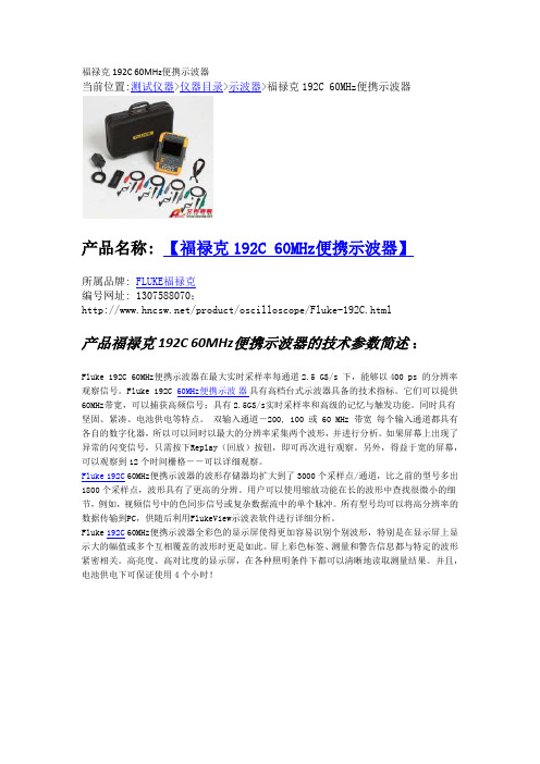
福禄克192C 60MHz 便携示波器当前位置:测试仪器>仪器目录>示波器>福禄克192C 60MHz 便携示波器产品名称: 【福禄克192C 60MHz 便携示波器】 所属品牌: FLUKE 福禄克编号网址: 1307588070;/product/oscilloscope/Fluke-192C.html产品福禄克192C 60MHz 便携示波器的技术参数简述Fluke 192C 60MHz 便携示波器在最大实时采样率每通道2.5 GS/s 下,能够以400 ps 的分辨率观察信号。
Fluke 192C :60MHz 便携示具有高档台式示波器具备的技术指标。
它们可以提供60MHz 带宽,可以捕获高频信号;具有2.5GS/s 实时采样率和高级的记忆与触发功能。
同时具有坚固、紧凑、电池供电等特点。
双输入通道-200, 100 或 60 MHz 带宽 每个输入通道都具有各自的数字化器,所以可以同时以最大的分辨率采集两个波形,并进行分析。
如果屏幕上出现了异常的闪变信号,只需按下Replay (回放)按钮,即可再次进行观察。
另外,得益于宽的屏幕,可以观察到12个时间栅格--可以详细观察。
波器Fluke 192C 60MHz 便携示波器的波形存储器均扩大到了3000个采样点/通道,比之前的型号多出1800个采样点,波形具有了更高的分辨。
用户可以使用缩放功能在长的波形中查找很微小的细节,例如,视频信号中的色同步信号或复杂数据流中的单个脉冲。
所有型号均可以将高分辨率的数据传输到PC ,供随后利用FlukeView 示波表软件进行详细分析。
Fluke 192C 60MHz 便携示波器全彩色的显示屏使得更加容易识别个别波形,特别是在显示屏上显示大的幅值或多个互相覆盖的波形时更是如此。
屏上彩色标签、测量和警告信息都与特定的波形紧密相关。
高亮度、高对比度的显示屏,在各种照明条件下都可以清晰地读取测量结果。
在线电能质量监测仪说明书讲解

在线电能质量监测仪说明书一、产品简介1、装置的特点我公司研制的HH-DZFII电能质量装置,采用DSP+ARM9为核心,DSP具有极强的数据处理能力用来完成数据的采集与计算,核心硬件处于国内先进水平。
ARM9用来进行数据的统计、显示、存储、按键、通讯和报警跳闸功能。
采用WINCE5.0嵌入式实时操作系统作为软件平台,全部软件采用高级语言编程,保证了系统的高可靠性和高移植性。
数据采集部分采用6通道、同步采样的16位高速A/D转换器,采集精度高,实测精度达到电能质量监测指标国家标准的要求;大容量的存储空间,满足电能质量监测装置对数据存储的要求,可保存一年以上的历史数据掉电不丢失。
采用了硬件锁相环技术,频率自动跟踪,防止了在电力系统频率变化时对监测指标的影响,防止了频率“泄漏”。
强大的通讯接口,装置配置了工业以太网,通讯速率高达100Mbps,还配置有RS232C、RS485、USB通讯接口,可选择多种通讯方式与远方管理中心交互数据;核心硬件采用四层印刷电路板(PCB)工艺和SMT工艺,硬件可靠性和电磁兼容能力达到国内先进水平,达到了国标对电能质量监测装置的EMC的要求。
在监测功能方面,装置除具有常规的电能质量稳态指标的监测外,还对电能质量的暂态扰动,主要是电压的骤升、骤降进行监测和记录,具有较强的实用性。
2、装置的主要功能(1)基本监测指标:电网频率、三相基波电压、电流有效值,基波有功功率、无功功率、功率因数、相位等;电压偏差、频率偏差、三相电压不平衡度、三相电流不平衡度、负序电压、电流;谐波(2~50次):包括电压、电流的总谐波畸变率、各次谐波含有率、幅值、相位。
(2)高级监测指标:间谐波、电压波动、闪变,电压骤升、骤降、短时中断、暂时过电压、瞬态过电压。
(3)显示功能:装置面板上带有大屏幕LCD显示器,实时显示电能质量监测指标的数据。
设置功能:可对装置基本参数、越限参数进行设置、修改和查看,并设有密码保护。
检测仪器操作说明书
维保检测仪器操作规程为了提高维保人员实际操作水平,全面提升维保工作,更好地服务于广大客户。
根据维保检测仪器功能、检测对象、国家标准等制定检测仪器操作规程。
一、设备名称:秒表名称:秒表量程:量程不小于15min;精度:0.1s应用范围:防火卷帘、消防电梯、火灾自动报警系统响应操作说明:1、检查仪器是否在检定有效期内。
2、使用前检查是否完好,开启关闭及各项功能正常。
3、每单项检测应重复两次,求平均值。
4、仪器使用后应置于干燥适宜的环境存放。
规范标准:*自动发电机组自动启动正常工作时间不应大于30s;*火灾自动报警系统响应时间不应大于30s;*湿式系统开启末端泄水装置5min内自动启动消防水泵;*干式系统开启末端试水装置1min内出水压力不应低于0.05MPa;*预作用系统火灾报警器确认火灾后2min,末端试水装置的出水压力不低于0.05MPa ;*泡沫系统做联动实验时从接到信号到喷射不宜(小于)二、设备名称:卷尺名称:卷尺量程:量程不小于30m;精度:1mm应用范围:测量室内、外消火栓间距、消防水带长度及设操作说明:1、检查仪器是否在检定有效期内。
外观完好、开启灵活。
2、在测量时需反复测量被测项目两次,求取平均值。
规范标准:1火灾探测器周围0.5m内不应有遮挡物。
2.手报距离地面1.3—1.5m。
3.从一个防火分区内任何一点到最近一个手报距离不大4.壁挂式火灾报警控制器底边距地面1.3—1.5m,靠近门5.柜式火灾报警控制器,当设备单列时正面操作距离不小于1.5m,双列时不小于2m,距墙维修距离不小于1.0m,6.水泵接合器距离消防水池或室外栓宜为15—40m。
7.地下式水泵接合器及室外地下栓至井口距离不宜大于8.室内消火栓及泡沫栓栓口中心距地1.1m。
9.室外消火栓距路边不超2m,距房屋外墙不小于5m。
10.报警阀组距离地高度宜为1.2m,两侧与墙距离不小于11.疏散指示标志在疏散走到应距地面1m以下。
检测仪说明书

一、概述LU192A智能电力监测仪(以下简称:LU192A)是一种具有可编程功能、自动化测量、数码管显示、电能累加、数字通讯等功能为一体的智能三相综合电力参数监测仪表。
它将三相交流电量按线性关系转换为规格化的数字量。
它集数字化、智能化、网络化于一身,使测量过程及数据分析处理实现自动化,减少人为失误,能够全面替代电量变送器、电度表、数显仪表、数据采集器等仪器,是组成电气自动化系统的理想产品。
其结构紧凑、电路先进、测量功能强大,是对传统仪表的革命性设计。
LU192A可广泛应用于电力、邮电、石化、煤炭、冶金、铁道、市政、智能大厦等行业、部门的电气装置、自动控制以及调度系统。
二、功能测量功能全LU192A功能强大,它集合了电量变送器、数字式电度表、数显表、数据采集器、记录分析仪、RTU 等仪器的部分或全部功能。
测量功能包括:一条三相四线制回路或其它任何线制的全部相电压/线电压(V)、电流(I)、功率(P、Q、S)、电能(Wh、Varh)、功率因数(PF),频率(f)及零序电流(I0)的功能。
数码管显示LU192A采用数码管显示,参数清晰易读,同时可显示多达3个参数,并能通过手动设定,按顺序读出超过20个参数。
-1-标准规约、轻松组网LU192A为了满足未来测量仪表的环境,备有RS-485串行口(或RS-232),允许连接开放式结构的局域网络。
应用Modbus 通讯规约,在PC或数据采集系统上运行的软件,能提供一个对于工厂、电厂、工业和建筑物的服务的简单、实用的电量管理方案。
自动稳零具有自动校准零点,克服零点随时间和温度的漂移。
实现所有参数的零点免调,提高了仪表的整体测量精度,提高了系统的整体稳定性,简化了校准流程。
极宽的动态输入范围LU192A采用量程自动切换技术,提供0~150V/450V(线电压600V)的电压输入量程,0~1A/5A电流输入量程,能自动适用于各种测量系统,无需任何硬件和软件的调整。
电缆路由探测仪说明书

3Dynatel 2273 高级电缆光缆外皮故障及路由探测仪操作手册简介:3Dynatel?2273高级电缆 / 光缆外皮故障及路由探测仪由发射器和接收器组成, 可用来探测地下电(光)缆的走向,同时亦可用于确定直埋电(光)缆的外皮绝缘故障点和架空电缆芯线的绝缘故障。
发射器可分别或同时发射四种不同频率的信号,以适于不同探测距离,电缆 / 光缆和土质等的要求。
它也可以发射一个单独的音信号用于线对和电缆 / 光缆的识别。
接收器提供四种定位模式以迅速确定电(光)缆外皮绝缘故障点及其走向,接收器还能测量电(光)缆的埋深以及其中的相对信号电流强度,并能检测50或60Hz的电力信号。
电池的安装和更换(见图)接收器参数设置1。
深度显示的单位设置(英寸,英尺,厘米):按住并保持,同时再按,选择所需单位。
2。
电力信号频率的设置:按住并保持,同时再按,选择50Hz或60Hz信号频率。
接收器电池电量测试接收器每次开机后,会自动进行2秒种的电池电量测试。
如要延长测试时间须持续按住。
测试时,显示条应超过电池电量标记();否则,应更换电池。
注:电量过低时,电量测试标记会闪烁显示。
发射器电池电量测试测试时,持续按住,观察显示屏并听信号音:电量足-持续音,且显示“OK”;电量低-蜂鸣音,且显示“LO”;需更换电池-无音信号,且显示“--”。
使用外部支流电源和5W信号输出发射机使用外部直流电源和使用内部电池一样能很好地工作。
用配件中所提供的点烟适配线将汽车上电池的直流电源连接到发射机上与信号输出口相邻的直流电源接口。
注意:内置电池不可用外部直流电源充电。
5W信号输出外部直流电源可以用于5W信号输出。
按一次选择3W输出,再按一次恢复5W输出。
3W输出时高输出指示打开,5W输出时高输出指示闪烁。
地下电(光)缆路由定位发射器设置按照以下三种方法中的一种向被测电(光)缆送信号音。
危险:超过240V的电压会损坏仪表。
警告:在用连接电缆连接被测电(光)缆时,请关闭发射器。
LU192系列电力监测仪说明书_V1.1(不适用H尺寸)
3.5.1 电源接线 ................................................................. 15 3.5.2 信号接线 ................................................................. 16 3.5.3 通讯接线 ................................................................. 19
4.1 显示面板........................................................................ 24 4.2 电参数显示.................................................................... 24
13、铱-192使用说明

YG-192使用说明随机附件YG-192源机驱动缆、三脚架源辫子(含源)手柄源导管源端子附件信息名称数量备注YG-192源机1台主机驱动缆1根长度据用户需求而定源辫子1根含源(100Ci)手柄1个随机带源导管1根长度据用户需求而定源端子1个随机带三脚架1个随机带(遥控器支架)1.重要数据由于精心设计制造,选择优质材料,快门操作容易,保证YG-192γ射线探伤仪具有最优的质量。
然而,由于伽玛探伤仪不能提供双结构动件,不能避免磨损。
因此,除了要监测YG-192γ射线探伤仪外,还要经常检查它的操作安全性。
同时强制性地规定用报警器作探伤仪的安全附件,必须严格遵守国家和国际法定的规程。
仅允许经过培训的操作人员使用γ射线探伤仪。
培训指后面的提级的内容:探伤仪的处理和维修,放射性保护及有关责任。
不小心疏忽和资格不足都会导致危险和发生放射性事故。
2.γ射线探伤仪总图前连接器把手底座放射性标识机体光闸快门导环钥匙后连接器3.γ射线探伤仪的原理完整的γ射线探伤仪包括有:工作容器、源辫子(含放射源)挠性源导管摇控器安全装置3.1工作容器,包括源辫子(含放射源)工作容器由贫铀屏蔽体、外壳、手柄、快门锁、源辫子锁定机构、前后连接器及保护帽构成。
当工作容器处于关闭位置时,源辫子(由钨节和拧紧并铆接在辫子上的一个不锈钢包壳内的放射源组成)定位在源通道内并由屏蔽材料将射线充分屏蔽。
用钥匙将锁打开,转动快门环至“OPEN”位置(不工作时快门环置于“CLOSED”位置),使偏心轮中的曝光通道和源通道对直,这样工作容器就打开了,此时的前连接器内有射线射出(在机器内有源的情况下)。
因此在不工作的情况下,切勿将快门打开,以防止误照射。
当工作容器没有连接源导管和遥控器时,工作容器的前后连接器要各盖一个保护帽以防止前后连接器损坏和污染。
工作容器属于P级,第二类,即是工作容器也是运输容器。
3.2挠性源导管的原理操作遥控器可使放射源在源导管中移动,从工作容器的停止位置伸到工作位置。
D100电能量采集终端用户手册v1.1

4.3.5 电表配置
单击配置菜单界面上的电表配置图标按钮,出现如下界面。
电表配置第一步
电表编号选定框:点击选定或直接输入1~~600数值范围的电表编号,进行配置
1.2技术特点
·完善的电源及通讯防雷保护措施
电源防雷处理。
所有通讯口采用光电隔离芯片,提高耐压及抗干扰能力。
通讯口输入端采用TVS过压保护芯片,有效的保护端口。
·数据安全性
系统采取多项措施以确保数据存取、系统配置和其他在系统上操作的安全性。
分级用户管理,如装置用户界面操作就分超级用户、校时用户、普通用户,各级用户对操作权限均不一样。
支持唯一时钟源功能,可配置只允许一个端口进行校时。
主站网络规约可对主站IP绑定,拒绝其他IP非法访问终端。
停电后,数据不丢失,且数据保持时间大于10年。
·支持实时显示终端CPU负荷及内存使用率。
·可通过抄表端口对每只电表进行通讯及数据采集调试,以便判断电表通信情况。
·可通过抄表端口、远传端口、网络端口对报文进行监视,并且可以存储报文,为分析、解决问题提供便利及准确的依据。
启用选择框:单击勾中状态则配置生效。
增加按钮:单击则以上操作信息被添加,并保存。
修改按钮:单击则以上操作信息被修改,并保存。
V-GL系列电子流量监测仪说明书

The V-seriesEletta Flow Monitorwith one adjustableswitchpoint•Rugged and sturdy design•Uses proven differential pressure technique•Economical alternative to more expensive flow meters •Liquids and gases can be monitored •Dependable and economical•One SPDT micro switch for adjustable flow alarm •Insensitivie to magnetic fieldsThe Pipe Section is constructed of copper alloy and fitted with BSP/NPT threads from 15 mm to 40mm (1/2’’–11/2”).V-GL series•Monitoring flows in cooling and lubricating circuits •Antifreeze protection of heat pump systems •Dry out protection•Starting and stopping pump motors•Mechanical switch works without external power •Low cost solution for difficult flow applications •Interchangeable control units to fit all pipe sections •Not affected by static pressureImportant applications and product featuresBenefits of the V-seriesThe Pipe Section has a flanged (wafer) process pipe connection and the material is bronze from 15 mm up to size 32 mm (1/2’’–11/4”) and painted cast iron in sizes40 mm to 400 mm (1 1/2"–16”).V-FA seriesThe Eletta Flow Monitor’s function is based on theproven and dependable differential pressure prin-ciple. This is perhaps the oldest and most widely used principle for flow metering, mainly because of its simplicity and its relatively low cost.The Eletta V-series Flow Monitor is used to control flow of liquids and gases in pipes from 15 mm to 500 mm. Through the adjustable SPDT micro switch it is possible to set one low or high flow alarm to protect expensive equipment in various piping systems. The switching point is highly repeatable, within <2%. The Flow Monitor is insensitive to surrounding magnetic fields and it com-bines the long-standing proven mechanical function with outstanding reliability. Together with an exceptio-nally sturdy and robust design, this makes it extremely well suited for difficult environments.The V-series comes in two measuring ratios designated V1 and V15, which means that the V1 has a flow measu-ring span of 1:2 and the V15 has a span of 1:5.Like all Eletta Flow Monitors the V-series can monitor both liquids and gases.All the Eletta Flow Monitors including the V-series can be fitted to any of the various Eletta Flow Monitor Pipe Sections to suit your application.The Instrument consists of two parts mainly, i.e. the Pipe Section and the Control Unit. The Pipe Section is the part that is to be mounted in the process pipe and the Control Unit is mounted directly (standard) or remote to the Pipe Section.As the Control Unit is pre-calibrated before leaving our production facilities, your can change pipe sections to fit other dimensions and materials than originally orde-red without recalibration.The Control Unit contains the micro switch which can be set to trip anywhere within the measuring range.The Pipe Sections come in Copper alloy, Stainless Steel, Cast Iron and sizes from DN 15/PN16 (ANSI 1/2”/150 lbs) up to DN 500/PN16 (ANSI 20”/150 lbs). The V-series Control Unit can also be used to supple-ment an already installed Eletta Flow Monitor such as the S- or D -series even after the installation.The Pipe Section is made from Stainless Steel and comes with BSP/NPT threads in size 15, 20 and 25 mm (1/2’’, 3/4” and 1”).The Pipe Section comes in stainless steel and has the same ”fit between flanges” (wafer) execution as the -FA series and process connections from 15 mm to 500 mm (1/2”–20”).V-GSS seriesV-FSS seriesThe V-series Flow MonitorModular designThe name Eletta has become synonymouswith flow monitoring in many industries world wide where the Products are appreciated for their sturdy and robust design.Eletta Flow Monitors are of our own proprietary design and our manufacturing as well as the whole company is certified to ISO 9001 and ISO 14000 quality standards. We export our Products all over the world and we have Authorized Distributors in most European countries, Australia, South Africa, India, Japan and USA.In our technical leaflets and manuals you will find full details of the design, pressure drop graphs, measuring ranges and dimensional drawings. We welcome you to our at all time updated web site at for the most recent and accurate information about Eletta and our Products. At this site you can find most of the documentation on down-loadable files. Whatever your request for information is, our e-mail address:***************is the fastest way to get in contact with our Customer Support and technical department. Of course, your local Eletta Distributor, whose address you can find in our homepage, can assist you in most cases.40E 1E 19Eletta Flow ABBox 5084, SE-141 05 Kungens Kurva, SwedenTel. +46 8 603 07 70 ***************Flow range: Min. flow: Wetted materials:Rubber parts: Max. pressure: Standards:Max. temp. Control Unit: 0,4 – 25 000 l/min (liquid)V1: 50% of the full scale flow range V15: 20% of the full scale flow rangeCopper alloy, painted cast iron. Seaworthy stainless steel 904L,stainless steel, 316Nitrile (HNBR), EPDM and Fluorinated rubber (FPM) 16 bar (232 PSI)PN 16/ANSI 150 lbs90°C standard, 120°C optional.Max. temp. Pipe Section: -GL and -FA: 120°C (248°F)-GSS, -FSS: 250°C (482°F)Enclosure:IP65 (NEMA4)Process Connection: DN 15-40, BSP/NPT threadDN 15-500 DIN/ANSI flange (wafer)Alarm:V1 and V15 have one (1) micro switch contact,independently adjustable within the ordered Flow range Micro switch spec:Contact surfaces are silver plated as standard.Type: SPDT Hystereses: 10%Rated voltage: 480 VAC/15ABreaking current: 15@125, 250, 480 VAC Resistive load: 2A@30 VDC0,4A@125 VDC 0,2A@230 VDCRepeatability:< 2% actualCE-approvals: The Eletta Flow Monitors conforms with the EU directive for low voltageno: 72/23/EEC (EN 60 204-1, Part 1.) and Electromagnetic compatibility according to the directive 89/336/EEC (EN 50081-1 and 50082-2)Complies with applicable parts in PE-Directive 97/23/EG Specifications V-seriesEletta Flow MonitorsFind out moreEx-version:The Ex versions of type V1 and V15 are designed to be usied in explosive atmos-pheres. Approved acc to the IECEx cert. scheme as an intrinsically safe apparatus acc to IEC 60079-0:2007 IEC 60079-11:21007 and IEC 60079-26:2006.We refer to leaflet V-ex version and V-manual for more information.。
ny192e液晶多功能仪表说明书

NY192E多功能电力仪表(版本号:1.02)使用说明书目录1、简述 (1)1.1功能 (1)1.2特点 (1)2、安装、接线与配置 (2)2.1尺寸与安装 (2)2.1.1 装置机械尺寸 (2)2.1.2 安装方式 (2)2.1.3 安装注意事项 (2)2.2接线与配置 (3)2.2.1 端子定义 (3)2.2.2 电气接线 (4)2.2.3 通讯连接 (4)2.2.4 接线注意事项 (4)3、操作指导 (4)3.1屏幕显示 (4)3.2数据读取 (5)3.3键盘编程说明 (7)3.3.1 用户密码确认 (7)3.3.2 功能设置 (8)3.3.3 CT、PT变比设置 (8)3.3.4 功率调试 (9)4、运输与贮藏 (10)5、保证期限及订货说明 (10)1、简述1.1 的功能多功能电力仪表是一款用于中低压系统(6—35KV和0.4KV)的智能化装置,它集数据采集和控制功能于一身,具有电力参数测量及电能计量为一体,其精度完全符合电能表国家标准、同时具有4路开关量输入监测、4路继电器输出(可选)、2路脉冲输出、提供通讯接口与计算机监控系统连接,支持RS485接口MODBUS通讯协议或多种协议。
1.2 的特点1.2.1 具有强大的数据采集和处理功能支持三相三线制和三相四线制,具有三相电压、三相电流、总有功功率、总无功功率、各相的有功及无功功率、功率因数、系统频率、正向有功电度、反向有功电度、正向无功电度、反向无功电度等测量,事件记录,与计算功能。
·具有2路继电器控制输出(可选);·具有2路开关量输入功能;·可当地查看运行状态;可查看或设定运行参数。
1.2.2 安全性高,可靠性好在设计过程中采用了多种抗干扰措施,能够在电力系统中稳定运行。
静电放电抗扰符合4级;电快速瞬变脉冲群抗扰性符合4级,高压冲击抗扰符合4级;浪涌抗扰符合3级;面板防护等级符合IP54;壳体防护等级符合IP20。
胜利仪器 VICTOR 9000F无线高低压叉型电流表说明书

仪表质量 工作温湿度 存放温湿度 干扰 绝缘杆尺寸 绝缘强度 结构
检测仪:宽 210mm×高 246mm×厚 45mm 接收器:宽 78mm×高 165mm×厚 42mm φ128mm 2 次/秒 0.00A~9999A(50/60Hz 自动) 0.01A 0.00A~9999A 全自动换档 ±2%rdg±5dgt (导线处于靠近钩形钳头底端中心位置,23℃±2℃) 被测导线应尽量处于靠近钩形钳头顶端中心位置,可直接挂在 线路上进行测量。远离钩形钳头顶部测试误差约增大一倍或更 多。(请参考检测仪操作部分第 3 点) 99 组,存储过程中“MEM”符号指示,“FULL”符号闪烁显示表 示存储已满 110kV 以下测试,带绝缘杆操作(可定制 500kV 以下测试) 通常测试模式下按 HOLD 键保持数据,“HOLD”符号显示,再按 HOLD 键取消 “MR”符号指示,能上下翻阅所存数据 超量程溢出功能:“OL A”符号显示 当接收器没有收到发射信号时动态显示“no- -”符号 开机约 15 分钟后,仪表自动关机,以降低电池消耗 当电池电压低于 4.8V 时,接收器显示电池电压低符号“ ” (检测仪低电压时闪烁显示,接收器低电压时持续显示),提醒 更换电池 检测仪:300g(含电池),接收器:280g(含电池) 仪表总质量:2300g(含绝缘杆和电池) -10℃~40℃;80%Rh 以下 -10℃~60℃;70%Rh 以下 尽量避免 315MHz、433MHz 同频信号干扰 约 4500mm AC 110kV/rms(伸缩绝缘杆完全拉开,两端之间) 防滴漏Ⅱ型
若被测线路电压超过 600V 必须连接绝缘杆使用。 由于高压线路很危险,操作者必须经严格培训并获得国家相关高压操作认证
才能使用本仪表进行现场测试。 严禁用本仪表测试电压超过 110KV 的导线或汇流母线。 注意本仪表面板及背板的标贴文字及符号。 请勿于高温潮湿,有结露的场所及日光直射下长时间放置和存放仪表。 更换电池,请注意电池极性,长时间不用本仪表,请取出电池。 拆卸、维修本仪表,必须由有授权资格的人员操作。 若本仪表的部件有损伤,请禁止使用。 由于本仪表原因,继续使用会带来危险时,应立即停止使用,并马上封存,
- 1、下载文档前请自行甄别文档内容的完整性,平台不提供额外的编辑、内容补充、找答案等附加服务。
- 2、"仅部分预览"的文档,不可在线预览部分如存在完整性等问题,可反馈申请退款(可完整预览的文档不适用该条件!)。
- 3、如文档侵犯您的权益,请联系客服反馈,我们会尽快为您处理(人工客服工作时间:9:00-18:30)。
5.1 通讯 ............................................................................... 41 5.1.1 接口及协议.............................................................. 41 5.1.2 通信数据计算方式 .................................................. 41 5.1.3 通讯联网 ................................................................. 43
LU-19 -
扩展功能选型(参考选型表"扩展功能"部分)
壳体选型----A:96*96
F:72*72
H:120*120
K:80*80
C: 96*48 产品功能型号(参考选型表"型号"栏)
Anthone Electronics Co.,Ltd.
Page 1
参数 型号 LU-190 LU-191 LU-192 LU-193 LU-192IU LU-192IW LU-192I LU-192U LU-192P LU-192Q LU-192C LU-192D
:该图标用于提醒你有人生安全危险,请遵循标志后的安全信息, 避免可能引起的人身伤害。
目录
一、概述 ......................................................................................1 1.1 功能及应用...................................................................... 1 1.2 选型说明 ......................................................................... 1
二、技术指标 ............................................................................... 5 三、安装及接线 ...........................................................................7
4.1 显示面板........................................................................ 24 4.2 电参数显示.................................................................... 24
3.5.1 电源接线 ................................................................. 15 3.5.2 信号接线 ................................................................. 16 3.5.3 通讯接线 ................................................................. 19
5.2 开关量输入.................................................................... 43 5.3 开关量输出.................................................................... 43
测量参数
U
I PQ
PF
F kWh
√ √ √√
√
√
√
√ √ √√
√
√
√
√ √ √√
√
√
√
√ √ √√
√
√
√
√ √--
-
-
-
-
√- -
-
-
√
-
√- -
-
-
-
√
-
--
-
-
-
-
- √-
-
-
-
-
-
-√
-
-
-
-
- --
√
-
-
-
-
--
√(角度)
-
-
kVarh √ √ √ √ -ห้องสมุดไป่ตู้
Page 2
Anthone Electronics Co.,Ltd.
5.3.1 按键设置 ................................................................. 43 5.3.2 通讯设置(选配通讯模块时) ................................ 44 5.3.3 通讯控制(选配通讯模块时) ................................ 45 5.4 变送输出 ....................................................................... 46 5.5 电能脉冲 ....................................................................... 46 六、维护与故障排除 ..................................................................47 6.1 维护需知 ....................................................................... 47 6.2 仪表维护 ....................................................................... 47 6.3 简单故障排除 ................................................................ 47
3.5.4 扩展模块接线 .......................................................... 23 四、操作说明 .............................................................................24
附录一 功能码 03H 基本数据区-参数编号............................ 50 附录二 功能码 03H 电能数据区 ............................................ 52 附录三 功能码 03H 系统参数区 ............................................ 53 附录四 功能码 06H 数据区.................................................... 57 附录五 功能码 10H 数据区.................................................... 60 附录六 通讯参数设置比例..................................................... 61 附录七 版本说明.................................................................... 61
扩展功能 显示方式
通讯及打印 变送输出 继电器输出 开关量输入 电能脉冲输出
●
-
-
-
-
点阵液晶
●
●
●
●
●
无
●
●
●
一、概述 1.1 功能及应用
LU-192 系列智能电力监测仪,是一种具备多功能、高精度及高可靠性的智能电力监 控装置,可以对电网中的电压、电流、有功功率、无功功率、视在功率、功率因数、频率、 电能等所有常用电参数进行测量,其强大的扩展功能模块,可以替代多种仪表,如变送器、 继电器和其它功能模块。
作为一种先进的智能化、数字化的电网采集终端,LU-192 系列电力监测仪可广泛应用 于电力系统、工矿企业、石油化工、公用设施、智能大厦等电力监控系统,实现远程网络自 动监控。 1.2 选型说明
4.2.1 电参数读数.............................................................. 24 4.2.2 显示界面切换 .......................................................... 30 4.3 编程操作........................................................................ 30 4.3.1 编程操作模式 .......................................................... 30 4.3.2 菜单结构................................................................ 32 4.3.3 参数查询 ................................................................ 35 4.4 编程操作实例 ................................................................ 37 4.4.1 输入数据示例 .......................................................... 37 4.4.2 基本参数编程示例................................................... 37 4.4.3 扩展模块编程示例................................................... 39 五、扩展模块 .............................................................................41
