GSe+pro+208+控标参数磁盘存储系统技术参数
208H系统调试说明书8页word文档
停车场设备接线及调试说明书208H型(422)Develop High-tech Limited Company成都新纪元高科技发展有限公司目录一.设备简介 (2)二.208H型停车设备详细配置 (2)三.设备系统控制图 (2)四、设备组成及功能简介 (2)4-2、出口刷卡票箱EP-DK06 (2)4-4. 设备主要通讯工具及接口 (3)五、设备接线方法 (3)5-2.道闸机控制器的接线方法 (3)208H道闸控制器接线端顺序图 (4)5-3、接口功能定义 (4)5-4、LED显示屏连接示意图 (4)六、设备调试方法 (5)七、停车场软件设备设置方法 (5)八、停车场系统设置 (6)九、软件里设备十六进制换算十进制地址方法 (6)十、常见故障 (7)一.设备简介208H道闸系统是由成都新纪元高科技发展有限公司自主研发及生产的智能停车系统,系统设计安全可靠,配有语音提示和指示灯向导,使客户操作更加简单。
该设备目前主要包含道闸机、车检器、发卡机、LED显示屏等其它可扩充产品。
该设备是目前市面上最先进的智能停车系统之一,拥有智能卡识别功能、蓝牙识别功能、地感识别功能、红外控制功能及强大的管理员设置功能。
二.208H型停车设备详细配置2-1.入口设备发卡机:发卡机芯、LED显示屏、读卡器、12V电源及箱体道闸机:减速箱、电机、控制器、闸杆及箱体2-2. 出口设备出口票箱:LED显示屏、读卡器、12V电源及箱体道闸机:减速箱、电机、控制器、闸杆及箱体2-3. 中控设备网络控制器、视频采集卡三.设备系统控制图3-1.设备外观安装实例3-2.设备布线示意图3-3系统设备布线方法注:设备422通讯布线方法(道闸机为208H型控制器)1、将出入口设备用网线串接起来,如422通讯网线从入口票箱与出口票箱串接后,再从出口票箱串接到电脑。
2、入口票箱接一根网线到入口道闸,出口票箱接一根网线到出口道闸机。
(注:系统需要接的线主要是票箱之间的422通讯线及票箱和道闸机之间的控制线。
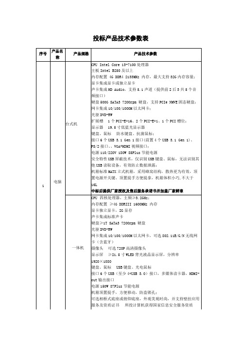
投标产品技术参数表
内存32MB
14
高清
电视
55寸
屏幕尺寸:55英寸智能电视:是
屏幕分辨率:超高清4K(3840x2160)
HDR显示:支持屏幕比例:16:9
背光源:LED背光方式:侧入式
3D显示:不支持亮度:1000流明以上
刷屏率:60HZ扫描方式:逐行扫描
水平视角(度)Байду номын сангаас±178°垂直视角(度):±178°
序号
产品名
称
产品规格
产品技术参数
1
电脑
台式机
CPUIntelCorei3-7100处理器
主板IntelB250及以上
内存配置4GDDR42133MHz内存,最大支持32G内存容量;
显卡集成显卡或独立显卡
声卡集成HDAudio,支持5.1声道(提供前2后3共5个音
频接口)
硬盘500GSATA37200rpm硬盘,支持PCIeNMVE固态硬盘;
键盘、鼠标USB键盘、光电鼠标
接口6个USB(至少4*USB3.0)接口,多媒体读卡器,HDMI-
out输出接口
电源150W87Plus节能电源
机箱顶置提手,方便移动,防盗锁孔;
可选相框式底座或俯仰底座,外观美观时尚,并支持壁挂应用
服务及资质证书所投计算机获得国家信息安全服务资质
(安全工程类一级)、制投厂商拥有IT环保处置服务,制造
外部纸架214㎜(8,.4″)?外径搭配76㎜(3″)纸芯
碳带轴心尺寸25.4㎜(1″)-76.2mm(3″)
碳带宽度25.4㎜~114㎜(1″~4.4″)
最大碳带长度300m通讯介面RS232,Centronics
aoc-sas2lp-h8ir参数
aoc-sas2lp-h8ir参数AOC-SAS2LP-H8IR参数解析AOC-SAS2LP-H8IR是一款SAS/SATA扩展卡,它提供了高性能的存储解决方案和灵活的扩展能力。
本文将对AOC-SAS2LP-H8IR的参数进行详细解析,帮助读者更好地了解该产品。
1. 接口类型AOC-SAS2LP-H8IR支持SAS(Serial Attached SCSI)和SATA (Serial ATA)两种接口类型。
SAS接口是一种高速、可靠的数据传输接口,适用于高性能的存储设备。
而SATA接口则更适合于普通的存储设备,如硬盘驱动器和光驱等。
2. RAID支持AOC-SAS2LP-H8IR内置的RAID控制器可支持多种RAID级别,包括RAID 0、RAID 1、RAID 5、RAID 10等。
RAID技术可以提高数据可靠性和性能,通过将数据分散存储在多个磁盘上,即使其中一个磁盘损坏,数据也能够正常访问。
3. 存储容量AOC-SAS2LP-H8IR支持8个SAS/SATA接口,每个接口支持6Gb/s的传输速率。
这意味着该扩展卡可以同时连接8个硬盘驱动器,提供较大的存储容量和更高的传输性能。
4. 支持热插拔AOC-SAS2LP-H8IR支持热插拔功能,用户可以在系统运行时插入或拔出硬盘驱动器,无需重启系统。
这大大简化了存储设备的维护和升级过程,提高了系统的可用性。
5. 兼容性AOC-SAS2LP-H8IR兼容多种操作系统,包括Windows、Linux和FreeBSD等。
无论您使用哪种操作系统,都可以轻松地安装和配置该扩展卡,实现高效的存储管理。
6. 硬件监控AOC-SAS2LP-H8IR内置了硬件监控功能,可以实时监测硬盘驱动器的状态和健康状况。
当硬盘驱动器出现故障或异常时,系统会及时发出警报,确保数据的安全性和可靠性。
7. 管理软件AOC-SAS2LP-H8IR配套的管理软件提供了丰富的功能,包括RAID配置、磁盘管理、性能监控等。
Moxa EDS-208系列产品说明书

P/N: 1802002080016*1802002080016*EDS-208 Series Quick Installation GuideMoxa EtherDevice SwitchVersion 5.2, January 2021Technical Support Contact Information/support2021 Moxa Inc. All rights reserved.OverviewThe EDS-208 series of Moxa EtherDevice™ Switches are entry-level8-port Ethernet Switches that provide a cost-effective solution for industrial Ethernet connections. EDS-208 provides a choice of 12 to 48 VDC power input. The switches can operate reliably in a temperature range of -10 to 60°C, and the rugged hardware design makes EDS-208 perfect for ensuring that your Ethernet equipment can be used in demanding industrial environments.Package ChecklistMoxa EDS-208 is shipped with the following items. If any of these items is missing or damaged, please contact your customer service representative for assistance.• 1 EDS-208 or EDS-208-M-SC or EDS-208-M-ST•Quick installation guide (printed)•Warranty cardFeaturesHigh Performance Network Switching Technology•10/100BaseT(X) (RJ45), 100BaseFX (SC/ST type, Multi-mode) •IEEE 802.3/802.3u/802.3x•Store and Forward switching process type, 1024 address entries Industrial Design•Operating temperature ranges from -10 to 60°C•Power inputs: 12 to 48 VDC•IP30, plastic case•DIN-Rail mounting abilityPanel Layout of EDS-2081.Heat dissipation orifices2.Terminal block for power inputand grounding3.Moxa Logo4.Power input LED5.10/100BaseT(X) Port6.TP port’s 100 Mbps LED7.TP port’s 10 Mbps LED8.DIN-Rail kitPanel Layout of EDS-208-M-SC/ST1.Heat dissipation orifices2.Terminal block for power inputand grounding3.Moxa Logo4.Power input LED5.10/100BaseT(X) Port6.TP port’s 100 Mbps LED7.TP port’s 10 Mbps LED8.FX port’s 100 Mbps LED9.100BaseFX Port10.DIN-Rail kitMounting Dimensions (unit = mm)DIN-Rail MountingThe plastic DIN-Rail attachment plate should already be fixed to the rear panel of EDS-208 when you take it out of the box. If you need to reattach the DIN-Rail attachment plate to EDS-208, make sure the DIN-Rail kit is situated towards the top, as shown in the figures below.STEP 1: Insert the top of the DIN-Rail into the slot. STEP 2:The DIN-Rail attachment unit will snap into place as shown below.To remove Moxa EDS-208 from theDIN-Rail, insert a flat-blade screwdriver horizontally into the DIN-Railkit under the EDS-208, and thenpull it upwards and releaseEDS-208 towards you away fromthe DIN-Rail.You may also take the following steps to remove the EDS-208 from the DIN-Rail.STEP 1: Press the middle of the flat side of the mounting kit as indicated. Pull the EDS-208 downwards.STEP 2:Release it towards you and away from the DIN-Rail.Wiring RequirementsYou should also pay attention to the following items:• Use separate paths to route wiring for power and devices. If powerwiring and device wiring paths must cross, make sure the wires are perpendicular at the intersection point.NOTE: Do not run signal or communications wiring and power wiring in the same wire conduit. To avoid interference, wires with different signal characteristics should be routed separately.• You can use the type of signal transmitted through a wire todetermine which wires should be kept separate. The rule of thumb is that wiring that shares similar electrical characteristics can bebundled together.• Keep input wiring and output wiring separated.•It is strongly advised that you label wiring to all devices in the system when necessary.Grounding EDS-208Grounding and wire routing help limit the effects ofnoise due to electromagnetic interference (EMI).Run the ground connection from the right mostcontact of the 3-contact terminal block to thegrounding surface prior to connecting devices.Wiring the Power InputsThe two left-most contacts of the 3-contact terminal block connector on EDS-208’s top panel are used for the DC input. Top and front views of one of the terminal block connectors are shown here.STEP 1: Insert the negative/positive DC wires intothe V-/V+ terminals.STEP 2: To keep the DC wires from pulling loose,use a small flat-blade screwdriver to tighten thewire-clamp screws on the front of the terminalblock connector.STEP 3: Insert the plastic terminal block connectorprongs into the terminal block receptor, which islocated on EDS’s top panel.Communication ConnectionsEDS-208 has 7 or 8 10/100BaseT(X) Ethernet ports, and 1 or 0 (zero) 100BaseFX (SC/ST-type connector) multi-mode fiber ports.10/100BaseT(X) Ethernet Port ConnectionThe 10/100BaseT(X) ports located on EDS-208’s front panel are used to connect to Ethernet-enabled devices.Below we show pinouts for both MDI (NIC-type) ports and MDI-X (HUB/Switch-type) ports, and also show cable wiring diagrams for straight-through and cross-over Ethernet cables.MDI Port PinoutsMDI-X Port Pinouts 8-pin RJ45 PinSignal 1Tx+ 2Tx- 3Rx+ 6 Rx- PinSignal 1Rx+ 2 Rx- 3 Tx+ 6 Tx-RJ45 (8-pin) to RJ45 (8-pin) Straight-Through Cable WiringRJ45 (8-pin) to RJ45 (8-pin) Cross-Over Cable Wiring100BaseFX Ethernet Port ConnectionThe concept behind the SC/ST port and cable is quite straightforward. Suppose you are connecting devices I and II. Contrary to electrical signals, optical signals do not require a circuit in order to transmit data.Consequently, one of the optical lines is used to transmit data from device I to device II, and the other optical line is used to transmit data from device II to device I, for full-duplex transmission.All you need to remember is to connect the Tx (transmit) port of device I to the Rx (receive) port of device II, and the Rx (receive) port of device I to the Tx (transmit) port of device II. If you make your own cable, we suggest labeling the two sides of the same line with the same letter (A-to-A and B-to-B, as shown below, or A1-to-A2 and B1-to-B2). SC-Port Pinouts SC-Port to SC-Port Cable WiringST-Port Pinouts ST-Port to ST-Port Cable WiringLED IndicatorsThe front panel of EDS-208 contains several LED indicators. The function of each LED is described in the table below.LED Color State DescriptionP AMBER OnPower is being supplied to the powerinputOffPower is not being supplied to thepower input10(TP) GREENOn TP port’s 10 Mbps link is active Blinking Data is being transmitted at 10 Mbps Off TP Port’s 10 Mbps link is inactive100(TP) GREENOn TP port’s 100 Mbps link is active BlinkingData is being transmitted at 100MbpsOff 100BaseTX Port’s link is inactive100M(FX) GREENOn FX port’s 100 Mbps link is active BlinkingData is being transmitted at 100MbpsOff 100BaseFX Port’s link is inactiveAuto MDI/MDI-X ConnectionThe Auto MDI/MDI-X function allows users to connect EDS-208’s10/100BaseTX ports to any kind of Ethernet device, regardless of how the Ethernet cable is wired. This means that you can use either astraight-through cable or cross-over cable to connect EDS-208 to Ethernet devices.Dual Speed Functionality and SwitchingEDS208’s 10/100 Mbps switched RJ45 port auto negotiates with the connected device for the fastest data transmission rate supported by both devices. All models of EDS-208 are plug-and-play devices, so that software configuration is not required at installation, or during maintenance. The half/full duplex mode for the switched RJ45 ports is user dependent and changes (by auto-negotiation) to full or half duplex, depending on which transmission speed is supported by the attached device.Switching, Filtering, and ForwardingEach time a packet arrives at one of the switched ports, a decision is made either to filter or to forward the packet. Packets with source and destination addresses belonging to the same port segment will be filtered, constraining those packets to one port, and relieving the rest of the network from the need to process them. A packet with destination address on another port segment will be forwarded to the appropriate port, and will not be sent to the other ports where it is not needed. Packets that are used in maintaining the operation of the network (such as the occasional multi-cast packet) are forwarded to all ports.EDS-208 operates in the store-and-forward switching mode, which eliminates bad packets and enables peak performance to be achieved when there is heavy traffic on the network.Switching and Address LearningEDS-208 has an address table that can hold up to 1,000 node addresses, which makes it suitable for use with large networks. The address tables are self-learning, so that as nodes are added or removed, or moved from one segment to another, EDS-208 automatically keeps up with new node locations. An address-aging algorithm causes the least-used addresses to be deleted in favor of newer, more frequently used addresses. To reset the address buffer, power down the unit and then power it back up. Auto-Negotiation and Speed SensingAll of EDS-208’s RJ45 Ethernet ports independently supportauto-negotiation for speeds in the 10BaseT and 100BaseTX modes, with operation according to the IEEE 802.3u standard. This means that some nodes could be operating at 10 Mbps, while at the same time, other nodes are operating at 100 Mbps.Auto-negotiation takes place when a “live” RJ45 cable is connected to the switch, and then each time a LINK is enabled. EDS-208 advertises its capability for using either 10 Mbps or 100 Mbps transmission speeds, with the device at the other end of the cable expected to similarly advertise. Depending on what type of device is connected, this will result in agreement to operate at a speed of either 10 Mbps or 100 Mbps.If an EDS-208 RJ45 Ethernet port is connected to a non-negotiating device, it will default to 10 Mbps speed and half-duplex mode, as required by the IEEE 802.3u standard.SpecificationsTechnologyStandards IEEE802.3, 802.3u, 802.3xProcessing Type Store and Forward, with IEEE802.3x fullduplex, non-blocking flow controlAddress Table Size 1,000 uni-cast addressesInterfaceRJ45 Ports 10/100BaseT(X) auto negotiation speed, F/Hduplex mode, and auto MDI/MDI-X connection Fiber Ports 100BaseFX ports (SC/ST connector)LED Indicators Power, 10/100 M (TP port), 100 M (FX port) PowerInput Voltage 12 to 48 VDCInput Current @ 24 VDC 0.07 A (EDS-208)0.1 A (EDS-208-M-SC/EDS-208-M-ST) Connection Removable 3-contact Terminal Block Overload CurrentPresentProtectionPresentReverse PolarityProtectionMechanicalCasing IP30 protection, plastic caseDimensions 40 x 109 x 95 mm (W x H x D)Weight 170 gInstallation DIN-RailEnvironmentOperating Temperature -10 to 60°C (14 to 140°F) Storage Temperature -40 to 70°C (-40 to 158°F)5 to 95% (non-condensing) Ambient RelativeHumidityRegulatory ApprovalsSafety UL 508EMI FCC Part 15, CISPR 32 class A EMS EN61000-4-2 (ESD),EN61000-4-3 (RS),EN61000-4-4 (EFT),EN61000-4-5 (Surge),EN61000-4-6 (CS)Shock IEC 60068-2-27Free Fall IEC 60068-2-32Vibration IEC 60068-2-6 WARRANTY 5 years。
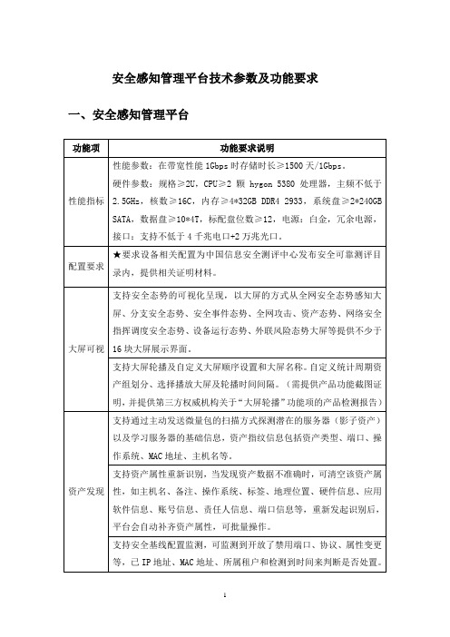
安全感知管理平台技术参数及功能要求
联动行为管理
支持联动原有行为管理设备,支持上网行为管理做资产用户名对接,精准识别终端资产责任人。(需提供截图打印加盖原厂公章证明)
★支持联动原有行为管理设备,支持与行为管理设备的联动,包含上网提醒、冻结账号等(需提供截图打印加盖原厂公章证明)
事后异常行为检测
具备元数据行为分析引擎:httpflow、dnsflow、adflow、icmpflow、maillflow等, 通过异常行为分析,结合各类机器学习算法完成未知威胁检测。包括:内网穿透、代理、远控、隧道、反弹shell等事后检测场景。
先进性
证明
为保障安全服务效果,满足数据和网络安全要求,所投态势感知平台产品厂商需通过可信云评估,提供相应的可信云认证报告
提供三年原厂质保及原厂免费现场服务,产品的安装、培训由原厂工程师完成实施。
二、
功能项
功能要求说明
性能规格
性能参数:网络层吞吐量≥1Gbps,应用层吞吐量≥500Mbps。
硬件参数:规格≥1U,内存大小≥8G,硬盘容量≥128G SSD,电源:单电源,接口:支持不低于6千兆电口+4千兆光口SFP。
配置要求
挖矿专项检测
支持挖矿专项检测页面,具备挖矿攻击事前、事中和事后全链路的检测分析能力,综合运用威胁情报、IPS特征规则和行为关联分析技术,如检测发现文件传输(上传下载)阶段的异常,对挖矿早期的准备动作即告警。
平台内置挖矿安全知识库,对常见的挖矿如:Bluehero挖矿蠕虫变种、虚拟货币挖矿、EnMiner挖矿病毒、PowerGhost挖矿病毒、DDG挖矿病毒、Docker挖矿、DDG挖矿变种、GroksterMiner挖矿病毒、Linux 挖矿木马、ZombieBoy挖矿木马等提供详细的背景介绍、感染现象、详细分析、相关IOC(MD5、C2、URL)、解决方案。
招标参数更正说明(精)

招标参数更正说明采购中心:由于之前我院购买网络设备制作的招标参数有一些不足,特在此作出更正。
1.“实验室管理控制设备”中的“实验室机架式管理控制设备”,第一项,“固化10/100M 以太网接口数量大于或等于3个”修改为“固化10/100M以太网接口数量大于或等于2个”。
2.“服务器实验”中,“机架式服务器”的参数只要能满足以下其中一类参数即可:A:1)高度2U2)CPU:1颗 Intel XEON E5530或AMD Opteron 2378四核处理器主频2.4GHz采用直连架构采用直连架构,集成内存控制器;主板支持2颗物理插槽的双核处理器及四核处理器;3)内存:2GB ECC DDR2 Registered内存;提供16根内存插槽;4)硬盘:1*146G 15K SAS HDD热插拔硬盘;最大可支持8个热插拔硬盘5)RAID:集成SAS RAID控制器,支持RAID 0,16)网卡:集成2*10/100/1000M自适应以太网卡;7)电源:600W 服务器专用电源;8)光驱:22X DVD-RW;9)服务:原厂五年有限保修,原厂商五年7*24小时免费现场服务,原厂提供服务承诺书原件;为确保整机质量与稳定性,提供原厂商或驻当地办事机构针对此次采购提供项目授权文件原件,供货时提供供货证明文件原件10)软件:Suse Linux Enterprise Server 10(含授权、介质);专业服务器系统备份还原软件,支持网络备份还原功能;专业服务器监控管理软件GridView;B:1)高度2U2)CPU:Intel XEON E5530或AMD Opteron 2378四核处理器;主频≥2.4 GHz;集成内存控制器;主板支持2颗物理插槽的四核处理器;3)内存:2 GB ECC内存;内存插槽数≥16根;4)硬盘:1 个146GB SAS热插拔硬盘;最大可扩展硬盘数≥85)RAID:支持RAID 0,16)网卡:二块10/100/1000M自适应以太网卡;7)电源:服务器专用电源;功率≥600W;8)外设:22X DVD-RW;9)服务:原厂五年硬件保修,原厂工程师五年7*24小时免费现场服务;(须提供设备生产厂家出具的服务承诺书原件并加盖鲜章)10)软件:Suse Linux Enterprise Server 10(含授权、介质);11)提供服务器配套的备份还原软件12)所投产品必须是厂商官方网站能够查询到的主流产品,提供生产厂家授权书、及其他资质证明文件3.“服务器实验”中,“塔式服务器”的参数只要能满足以下其中一类参数即可:A: 1)标准塔式服务器机箱2)CPU:1颗 Intel XEON E5530或AMD Opteron 2378 2.4G 四核处理器采用直连架构采用直连架构,集成内存控制器;主板支持2颗物理插槽的四核处理器;3)内存:2GB Registered ECC DDRII 667内存; 16根内存插槽;最大支持64GB内存;4)硬盘:2*500G SATA HDD 热插拔硬盘;最大支持8块热插拔硬盘;5)RAID:支持RAID 0,1,56)网卡:2*10/100/1000M自适应以太网卡;7)光驱:16X DVD光驱;8)电源:600W服务器专用单电源;9)服务:原厂五年有限保修,原厂商五年7*24小时免费现场服务,原厂提供服务承诺书原件;为确保整机质量与稳定性,提供原厂商或驻当地办事机构针对此次采购提供项目授权文件原件,供货时提供供货证明文件原件10)扩展:支持CIM切换管理模块,支持 DCMM2远程智能监控管理系统;11)软件:Suse Linux Enterprise Server 10(含授权、介质);专业服务器系统备份还原软件,支持网络备份还原功能;专业服务器监控管理软件GridView;B:1)高度≥2U2)CPU:Intel XEON E5530或AMD Opteron 2378四核处理器;主频≥2.4 GHz;集成内存控制器;主板支持2颗物理插槽的四核处理器;3)内存:2 GB ECC内存;内存插槽数≥8根;4)硬盘:2 个500GB SATA热插拔硬盘;5)RAID:支持RAID 0,1,56)网卡:二块10/100/1000M自适应以太网卡;7)电源:服务器专用电源;功率≥600W;8)外设:22X DVD-RW,标准软驱;9)服务:原厂五年硬件保修,原厂工程师五年7*24小时免费现场服务;(须提供设备生产厂家出具的服务承诺书原件并加盖鲜章)10)软件:Suse Linux Enterprise Server 10(含授权、介质);11)所投产品必须是厂商官方网站能够查询到的主流产品,提供生产厂家授权书、及其他资质证明文件。
aoc-sas2lp-h8ir参数

aoc-sas2lp-h8ir参数AOC-SAS2LP-H8IR参数介绍AOC-SAS2LP-H8IR是一款高性能的RAID控制卡,广泛应用于服务器和存储设备中,为用户提供可靠的数据保护和高效的存储解决方案。
本文将对AOC-SAS2LP-H8IR的参数进行详细介绍,帮助读者更好地了解该产品。
一、接口和通道数量AOC-SAS2LP-H8IR具有8个SAS/SATA通道,支持最高6Gb/s的数据传输速率。
这意味着用户可以同时连接多个硬盘或SSD,实现高速数据传输和存储容量的扩展。
二、RAID功能该控制卡支持多种RAID级别,包括RAID 0、RAID 1、RAID 10、RAID 5和RAID 50。
不同的RAID级别适用于不同的应用场景,用户可以根据自己的需求选择最合适的RAID级别,实现数据的冗余备份和性能优化。
三、缓存和处理器AOC-SAS2LP-H8IR内置256MB DDR2缓存,配备高性能的RAID处理器,能够快速处理大量的数据请求。
这种设计可以有效提升存储系统的性能,缩短数据读写时间,提高用户的工作效率。
四、硬盘支持该控制卡支持SAS和SATA接口的硬盘,兼容各种规格的硬盘,包括2.5英寸和3.5英寸的硬盘。
无论是企业级应用还是个人用户,都可以根据自己的需求选择适合的硬盘进行组建。
五、管理软件AOC-SAS2LP-H8IR配套了一套强大的管理软件,可以帮助用户方便地进行存储管理和配置。
用户可以通过管理软件监控硬盘的状态,进行故障诊断和修复,实现智能化的存储管理。
六、兼容性该控制卡在兼容性方面表现优异,支持多种操作系统,包括Windows、Linux和FreeBSD等。
无论用户使用哪种操作系统,都可以轻松地安装和配置AOC-SAS2LP-H8IR,实现高效的存储管理。
七、可靠性和安全性AOC-SAS2LP-H8IR采用了先进的数据保护技术,支持热插拔功能和热备份功能,可以在硬件故障时保护数据的完整性。
莫加EDS-208系列8口基础级无管理以太网交换机特点和优势说明书
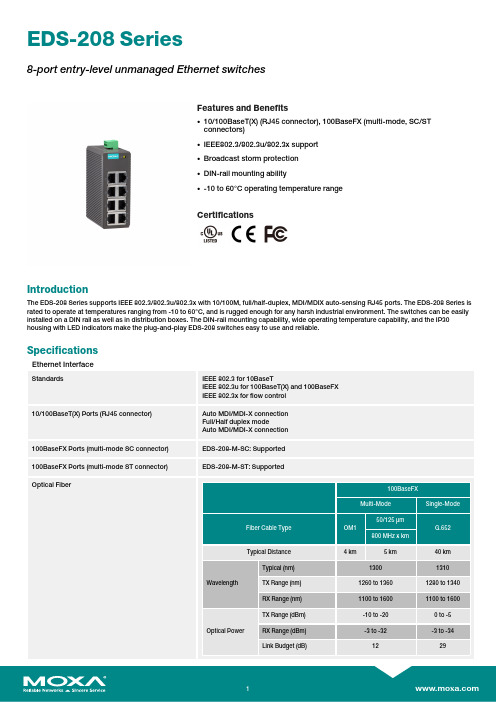
EDS-208Series8-port entry-level unmanaged Ethernet switchesFeatures and Benefits•10/100BaseT(X)(RJ45connector),100BaseFX (multi-mode,SC/STconnectors)•IEEE802.3/802.3u/802.3x support •Broadcast storm protection •DIN-rail mounting ability•-10to 60°C operating temperature rangeCertificationsIntroductionThe EDS-208Series supports IEEE 802.3/802.3u/802.3x with 10/100M,full/half-duplex,MDI/MDIX auto-sensing RJ45ports.The EDS-208Series is rated to operate at temperatures ranging from -10to 60°C,and is rugged enough for any harsh industrial environment.The switches can be easily installed on a DIN rail as well as in distribution boxes.The DIN-rail mounting capability,wide operating temperature capability,and the IP30housing with LED indicators make the plug-and-play EDS-208switches easy to use and reliable.SpecificationsEthernet InterfaceStandardsIEEE 802.3for 10BaseTIEEE 802.3u for 100BaseT(X)and 100BaseFX IEEE 802.3x for flow control 10/100BaseT(X)Ports (RJ45connector)Auto MDI/MDI-X connection Full/Half duplex modeAuto MDI/MDI-X connection 100BaseFX Ports (multi-mode SC connector)EDS-208-M-SC:Supported 100BaseFX Ports (multi-mode ST connector)EDS-208-M-ST:SupportedOptical Fiber100BaseFXMulti-ModeSingle-ModeFiber Cable TypeOM150/125µmG.652800MHz x kmTypical Distance4km5km40km WavelengthTypical (nm)13001310TX Range (nm)1260to 13601280to 1340RX Range (nm)1100to 16001100to 1600Optical PowerTX Range (dBm)-10to -200to -5RX Range (dBm)-3to -32-3to -34Link Budget (dB)1229800Dispersion Penalty(dB)31Note:When connecting a single-mode fiber transceiver,we recommend using anattenuator to prevent damage caused by excessive optical power.Note:Compute the“typical distance”of a specific fiber transceiver as follows:Linkbudget(dB)>dispersion penalty(dB)+total link loss(dB).Switch PropertiesProcessing Type Store and ForwardMAC Table Size2KPacket Buffer Size768kbitsPower ParametersInput Voltage24VDCInput Current EDS-208:0.07A@24VDCEDS-208-M Series:0.1A@24VDCOperating Voltage12to48VDCConnection1removable3-contact terminal block(s)Overload Current Protection 2.5A@24VDCReverse Polarity Protection SupportedPhysical CharacteristicsHousing PlasticIP Rating IP30Dimensions40x100x86.5mm(1.57x3.94x3.41in)Weight170g(0.38lb)Installation DIN-rail mountingEnvironmental LimitsOperating Temperature-10to60°C(14to140°F)Storage Temperature(package included)-40to85°C(-40to185°F)Ambient Relative Humidity5to95%(non-condensing)Standards and CertificationsSafety UL508EMC EN55032/24EMI CISPR32,FCC Part15B Class AEMS IEC61000-4-2ESD:Contact:4kV;Air:8kVIEC61000-4-3RS:80MHz to1GHz:3V/mIEC61000-4-4EFT:Power:1kV;Signal:0.5kVIEC61000-4-5Surge:Power:1kV;Signal:1kVIEC61000-4-6CS:3VIEC61000-4-8PFMFShock IEC60068-2-27Vibration IEC60068-2-6Freefall IEC60068-2-31MTBFTime EDS-208:401,624hrsEDS-208-M Series:368,353hrs Standards Telcordia(Bellcore),GB WarrantyWarranty Period5yearsDetails See /warranty Package ContentsDevice1x EDS-208Series switch Documentation1x quick installation guide1x warranty card DimensionsOrdering InformationModel Name 10/100BaseT(X)PortsRJ45Connector100BaseFX PortsMulti-Mode STConnector100BaseFX PortsMulti-Mode SCConnectorHousing Material Operating Voltage Operating Temp.EDS-2088––Plastic12-48VDC-10to60°C EDS-208-M-ST71–Plastic12-48VDC-10to60°C EDS-208-M-SC7–1Plastic12-48VDC-10to60°CAccessories(sold separately)Power SuppliesDR-120-24120W/2.5A DIN-rail24VDC power supply with universal88to132VAC or176to264VAC input byswitch,or248to370VDC input,-10to60°C operating temperatureDR-452445W/2A DIN-rail24VDC power supply with universal85to264VAC or120to370VDC input,-10to50°C operating temperatureDR-75-2475W/3.2A DIN-rail24VDC power supply with universal85to264VAC or120to370VDC input,-10to60°C operating temperatureMDR-40-24DIN-rail24VDC power supply with40W/1.7A,85to264VAC,or120to370VDC input,-20to70°Coperating temperatureMDR-60-24DIN-rail24VDC power supply with60W/2.5A,85to264VAC,or120to370VDC input,-20to70°Coperating temperatureRack-Mounting KitsRK-4U19-inch rack-mounting kit©Moxa Inc.All rights reserved.Updated Feb19,2020.This document and any portion thereof may not be reproduced or used in any manner whatsoever without the express written permission of Moxa Inc.Product specifications subject to change without notice.Visit our website for the most up-to-date product information.。
图形工作站配置参数

保修
厂家三年保修及人工服务
号条款为必须满足项,需提供证明文件
7
光驱
DVD-ROM
8
网卡
万兆网卡*2
9
外部接口
Realtek ALC662/前置接口:自带闪亮பைடு நூலகம்示灯,USB 3.0接口2个,灵动扩展区支持1394,eSATA/支持9合1SD读卡器/6个(其中4个USB3.0接口)/2个 PCIe 3.0 x16 插槽/1个PCIe x8 插槽/1个PCIe x4 插槽/2个5.25" 外置托架;
4
内存
16GB DDR4 RDIMM,最少支持4条内存插槽
5
硬盘
1块2TB SATA 3.5硬盘,1块2TB M.2 PCIe SSD硬盘/Raid 支持RAID 0,RAID 1,RAID 5 和RAID 10;
6
显卡
1块NVIDIA RTX A4000 16GDDR6 显卡,3条高清视频连接线;
图形工作站
图形工作站配置参数
数量:16套
序号
指标项
技术规格要求
1
品牌类型
国内知名品牌
2
显示器
24英寸LED背光,分辨率3840×2160,亮度500cd/㎡,刷新率60Hz,色数10亿,与主机同一品牌。
3
CPU
IntelXeon Skylake-W2223,4Cores,3.6GHz,8.25MB Cache,DDR4-2666, Turbo, 120W;
10
电源
950W电源
11
操作系统
正版 Windows10专业版操作系统64位
12
机箱
塔式机箱,175 x 426 x 375 mm/标配内置扬声器
兰贝208电话交换机模块说明书

目录注意事项、技术事项清除特许拨号字头名称和位置、术语和符号弹性编码功能设置指令表更改分机号码系统编程恢复分机号码进入系统编程设定分机打出方式更改系统密码设定分机打出方式设置开通外线取消全部分机打出方式外线分组设置拍叉簧的闪断时间设置某外线为某几部分机的专线设置分机呼出限制设置某分机只能使用某外线取消分机呼出限制设置打入时响铃分机恢复出厂状态设置值班方式使用方法设置全部外线人工值班人工值班设置全部外线电脑值班电脑值班设置某些外线为电脑值班打出设置第一值班分机拨打外线设置第二值班分机拨打内线监听语音信息征询转接录入语音信息三方通话监听音乐代接电话设定分机呼出等级及限拨字头设置离位转移设置某部分机等级取消离位转移设置全部分机等级强插和监听加入A组市话限拨字头自报分机号码清除A组市话限拨字头操作简明表加入B组市话限拨字头清除B组市话限拨字头加入特许拨号字头HL8120X-208A多媒体信息箱语音交换机模块使用手册宁波兰贝信息科技有限公司地址:电话:传真:安装注意事项,请仔细阅读:1、注意事项①本机应安装在干燥、通风、平稳、牢固的室内地方,布线使用专用电话线与本机连接。
②请勿将交换机与其它产生大电磁干扰源的设备(如马达、大变压器等)放置一起。
③所有分机配线必须避免与电源线或天线放在同一管线。
④避免损坏电源电缆,避免水溅雨淋,如有水进入机内,立即断电确保安全。
⑤在雷电期间,不要检修室外电话线路。
电源及接地:可靠稳定的电源是系统正常运行的保证,本系统工作电压为交流220V±10%50HZ,50,建议用户在安装本机时,使用独立于其他设备的电源,在电源电压不稳定的地区,建议使用交流稳压电源。
本机配有防雷装置,但要求有可靠的接地,否则防雷将不起作用。
技术参数:电源电压:AC220V±10% 50HZ功耗:≤20V A 交换制式:模拟空分电话机类型:双音多频拨号方式:音频方式外线音:电信局音源内线拨号音:450HZ 正弦波连续内线回铃音:450HZ 正弦波一秒通四秒断(IS:4S)系统功能设置:总机要用双音频电话机,系统编程必须在1号端口操作,进入系统编程须输入系统密码。
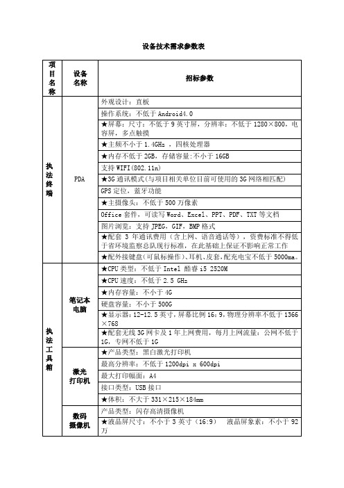
设备技术需求参数表
硬件
应用
服务器
级别:企业级
处理器:支持全部AMD Opteron 6200系列
★主频:不低于2.4GHz,核心数:8核,处理器个数:不低于4颗处理器,
处理器高速缓存:L3 cache不小于16M
应用层级:三层
★MAC地址表:不低于32K
堆叠功能:可堆叠
支持4K个VLAN,Guest VLAN、Voice VLAN
支持基于MAC/协议/IP子网/策略/端口的VLAN
支持1:1和N:1 VLAN交换功能
执法工具箱
笔记本
电脑
★CPU类型:不低于Intel酷睿i5 2520M
★CPU速度:不低于2.5 GHz
★内存容量:不小于4G
硬盘容量:不小于500G
★显示器:12-12.5英寸,屏幕比例16:9,物理分辨率不低于1366×768
★配套无线3G网卡及1年上网费用,每月上网流量:公网不低于1G,专网不低于1G
支持单个用户访问服务的上行/下行带宽占用量控制。
链路繁忙控制
支持基于链路负荷情况的优化控制机制,能根据链路的上行/下行带宽占用率情况执行对出站/入站流量的高级调度策略。(提供界面证明)
★服务器繁忙控制
支持面向服务器健康度的弹性调控机制,可通过监控业务流中的TCP传输异常来衡量服务器节点的有效性,尝试对性能不足的服务器临时开启过载保护,动态调节服务器的负载。(提供界面证明)
标配硬盘容量:配置4块300GB 1.5万转3.5英寸热插拔硬盘纠错,最大硬盘容量不低于16TB,,
★,,,,,RAID模式:支持RAID0, 1.可选RAID5.配置单独的阵列控制器,缓存≥512MB,支持有电池保护,可升级支持RAID 6
SCALANCE XF208 产品说明书
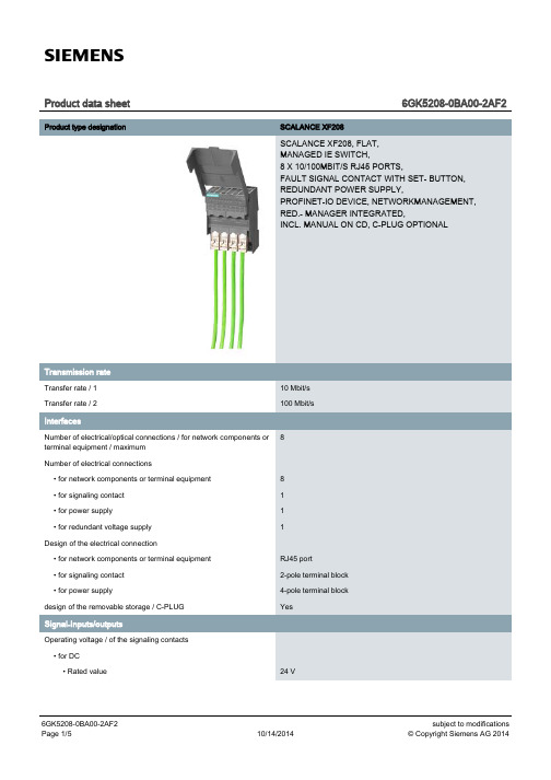
Product data sheet6GK5208-0BA00-2AF2 Product type designation SCALANCE XF208SCALANCE XF208, FLAT,MANAGED IE SWITCH,8 X 10/100MBIT/S RJ45 PORTS,FAULT SIGNAL CONTACT WITH SET- BUTTON,REDUNDANT POWER SUPPLY,PROFINET-IO DEVICE, NETWORKMANAGEMENT,RED.- MANAGER INTEGRATED,INCL. MANUAL ON CD, C-PLUG OPTIONALTransfer rate / 110 Mbit/sTransfer rate / 2100 Mbit/s8Number of electrical/optical connections / for network components orterminal equipment / maximumNumber of electrical connections• for network components or terminal equipment8• for signaling contact1• for power supply1• for redundant voltage supply1Design of the electrical connection• for network components or terminal equipment RJ45 port• for signaling contact2-pole terminal block• for power supply4-pole terminal blockdesign of the removable storage / C-PLUG YesOperating voltage / of the signaling contacts• for DC• Rated value24 VOperating current / of the signaling contacts• for DC• maximum0.1 AType of voltage / of the supply voltage DCSupply voltage / external24 V• minimum18 V• maximum32 VProduct component / fusing at power supply input YesFuse protection type / at input for supply voltage1,1 A / 33 VConsumed current / maximum0.13 AActive power loss / for DC / at 24 V 3.12 WAmbient temperature• during operation-40 … +60 °C• during storage-40 … +70 °C• during transport-40 … +70 °C• Note If the IE switch XF 200 is installed horizontally a maximum ambienttemperature of +40 °C is permittedRelative humidity• at 25 °C / without condensation / during operation / maximum95 %Protection class IP IP20Design FlatWidth75 mmHeight125 mmDepth73 mmNet weight0.25 kgMounting type• 35 mm DIN rail mounting Yes• wall mounting No• S7-300 rail mounting No• S7-1500 rail mounting No50Cascading in the case of a redundant ring / at reconfiguration time of<\~0.3\~sCascading in cases of star topology Any (depending only on signal propagation time)Product function• CLI Yes• web-based management Yes • MIB support Yes • TRAPs via email Yes • Configuration with STEP 7Yes • Port mirroring Yes • multiport mirroring No • with IRT• PROFINET IO switch No • PROFINET IO diagnosis Yes • switch-managed Yes Protocol / is supported• Telnet Yes • HTTP Yes • HTTPS Yes • TFTP Yes • FTP Yes • BOOTP No • DCP Yes • LLDP Yes Identification & maintenance function• I&M0 - device-specific information Yes • I&M1 – higher-level designation/location designation Yes Protocol / is supported• SNMP v1Yes • SNMP v2Yes • SNMP v3YesProduct function• Port diagnostics Yes • Statistics Packet Size Yes • Statistics packet type Yes • Error statistics YesProduct function• DHCP client YesProduct function• Ring redundancy Yes • High Speed Redundancy Protocol (HRP)Yes• high speed redundancy protocol (HRP) with redundancyYesmanager• high speed redundancy protocol (HRP) with standby redundancy No• Media Redundancy Protocol (MRP)Yes• media redundancy protocol (MRP) with redundancy manager Yes• Passive listening YesProtocol / is supported• SSH YesProduct function / SICLOCK support YesProtocol / is supported• NTP No• SNTP YesStandard• for FM FM3611: Class 1, Divison 2, Group A, B, C, D / T4, CL.1, Zone 2,GP. IIC, T4• for hazardous zone EN 60079-0: 2006, EN60079-15: 2005, II 3 G Ex nA II T4, KEMA 07ATEX 0145 X• for safety / from CSA and UL UL 60950-1, CSA C22.2 No. 60950-1• for hazardous zone / from CSA and UL ANSI / ISA 12.12.01, CSA C22.2 No. 213-M1987, CL. 1 / Div. 2 / GP.A, B, C, D T4, CL. 1 / Zone 2 / GP. IIC, T4• for emitted interference EN 61000-6-4:2001 (Class A)• for interference immunity EN 61000-6-2:2001Certificate of suitability EN 61000-6-2:2001, EN 61000-6-4:2001• CE marking Yes• C-Tick Yes• KC approval Yes• Railway application in accordance with EN 50155No• Railway application in accordance with EN 50124-1NoMarine classification association• American Bureau of Shipping Europe Ltd. (ABS)No• Bureau Veritas (BV)No• Det Norske Veritas (DNV)No• Germanische Lloyd (GL)No• Lloyds Register of Shipping (LRS)No• Nippon Kaiji Kyokai (NK)No• Polski Rejestr Statkow (PRS)NoMTBF / at 40 °C54.8 aMTBF54.8 aInternet-Link• to website: Selector SIMATIC NET SELECTION TOOL /snst• to website: Industrial communication /simatic-net• to website: Information and Download Center /automation/net/catalog• to website: Image database /bilddb• to website: CAx Download Manager /cax• to website: Industry Online Support Security information Siemens provides products and solutions with industrial securityfunctions that support the secure operation of plants, solutions,machines, equipment and/or networks. They are importantcomponents in a holistic industrial security concept. With this inmind, Siemens’ products and solutions undergo continuousdevelopment. Siemens recommends strongly that you regularlycheck for product updates. For the secure operation of Siemensproducts and solutions, it is necessary to take suitable preventiveaction (e.g. cell protection concept) and integrate each componentinto a holistic, state-of-the-art industrial security concept. Third-partyproducts that may be in use should also be considered. For moreinformation about industrial security, visit/industrialsecurity. To stay informed aboutproduct updates as they occur, sign up for a product-specificnewsletter. For more information, visit. (V3.4)letzte Änderung:Oct 13, 2014。
集群存储系统技术参数

1.元数据管理基本软件,提供存储数据的逻辑视图,文件名列表及目录结构,组织物理存储介质数据分布,ClientCache一致性管理等。
2.元数据服务集群管理软件。
3.集群源系统技术,分割管理统一名字空间。
4.数据灵活冗余软件,可以根据数据重要性灵活调节冗余度。
5.系统自动恢复软件,无需中断业务和人工干预,故障系统调度,系统自动恢复,无缝加入,系统IO性能影响不超过15%
1
套
2
服务器
2U12盘位机器,戴尔R720
产品类别:机架式;产品结构:2U;CPU型号:Xeon E5-2603;CPU数量:2颗;主板芯片组:Intel C600;内存:8GB ECC DDR3;硬盘接口类型:SATA/SAS/SSD;硬盘位:12个;硬盘:500GB SAS系统盘;磁盘控制器:PERC H310;网卡:四端口千兆网卡;电源功率:495W
15.单个集群子系统的所有硬盘同时发生故障不影响系统在线服务,且数据自动迁移。
16.支持32/64位操作系统:Microsoft Windows 2000,WindowsServer 2003,Windows XP,Windows 2008,RedHat Linux,Centos,Suse/OpenSuse,MacOS。
10.系统提供预处理技术,提高数据访问效率。
11.系统内置删除权限设置,可在线禁止操作端删除操作,防止操作端误删除数据。
12.支持动态在线扩展/删除集群子系统,按需增加/减少单卷容量,无须停止应用。
13.系统内置数据迁移工具,可按需开启、关闭数据迁移进程,无需停止应用。
14.任意集群子系统单位或集群源系统单位发生故障时,不影响业务正常读写,并且无需管理员即时进行维护操作。
HDS_VSP_G200安装配置指南
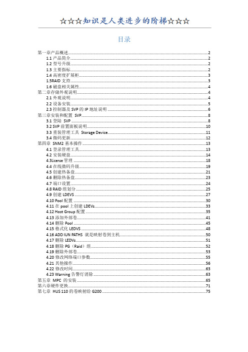
目录第一章产品概述 (2)1.1产品简介 (2)1.2型号升级 (2)1.3主要指标 (2)1.4高密度扩展柜 (3)1.5RAID支持 (3)1.6磁盘相关属性 (4)第二章存储外观说明 (4)2.1外观说明 (4)2.2设备安装 (5)2.3控制器及SVP的IP地址说明 (6)第三章安装和配置SVP (8)3.1登陆SVP (8)3.2 SVP前置面板说明 (10)3.3重装管理工具Storage Device (11)3.4微码更新 (12)第四章SNM2基本操作 (13)4.1登录管理工具 (13)4.2安装硬盘 (14)4.3Li ce n se管理 (18)4.4在线微码升级 (19)4.5创建热备盘 (21)4.6删除热备盘 (23)4.7端口设置 (24)4.8 RAID组划分 (25)4.9创建LDEVS (27)4.10 Pool配置 (30)4.11在pool上创建LDEVs (33)4.12 Host Group配置 (35)4.13添加外部卷 (41)4.14删除Pool (45)4.15格式化LEDVS (48)4.16 ADD lUN PATHS 就是映射卷到主机 (50)4.17删除LEDVs (51)4.18删除PG(Raid)组 (52)4.19删除外部卷 (53)4.20修改网络端口参数 (55)4.21其他操作 (56)4.22修改时间 (63)4.23 Warning告警灯消除 (63)第五章MPC 的安装 (65)第六章硬件更换 (71)第七章HUS 110的卷映射给G200 (75)第一章产品概述1.1产品简介HDS VSPGx00(Panama)系列主要包含以下几个产品:G200、G400、G600、G800,是HDS新一代中高端存储产品。
该系列产品统一运行的存储操作系统为SVOS。
1.2型号升级存储产品的型号升级,主要是指G400到G600之间的升级,G400可通过购买升级license包及相应的硬件【前后端接口和内存】,可实现无中断应用在线升级到G600,从而提升存储系统的性能。
GPS-208用户手册说明书

GPS-208USER MANUALCES WIRELESS TECHNOLOGIES, CORP.925-122 South Semoran BoulevardWinter Park, Florida 32792GPS208 Manual v1p1.docRevision 1.1November 1, 2011© Copyright CES WIRELESS TECHNOLOGIES CORP. (2011)The information contained in this document is subject to change without notice and should not be construed as a commitment by CESWIRELESS TECHNOLOGIES CORP. unless such commitment is expressly given in a covering document.REGULATORY COMPLIANCEFCCThis device complies with Part 15 of the FCC Rules. Operation is subject to the following two conditions: (1) This device may not cause harmful interference, and (2) this device must accept any interference received, including interference that may cause undesired operation.This equipment has been tested and found to comply with the limits pursuant to Part 15 Subpart B, Part 22, and Part 24 of the FCC rules. These limits are designed to provide reasonable protection against harmful interference in an appropriate installation. This equipment generates, uses, and can radiate radio frequency energy and, if not used in accordance with instructions, can cause harmful radiation to radio communication. However, there is no guarantee that interference will not occur in a particular installation.RF EXPOSUREYour device is a radio transmitter and receiver. It is designed and manufactured not to exceed the emissions limits for exposure to radio frequency (RF) energy set by the Federal Communications Commission (FCC) of the U.S. Government. These limits are part of comprehensive guidelines and establish permitted levels of RF energy for the general population. These guidelines are based on the safety standards previously set by the U.S. and international standards bodies. The standards include a substantial safety margin designed to assure the safety of all persons, regardless of age and health.The exposure standard for wireless RF devices, such as the device, employs a unit of measurement known as the Specific Absorption Rate, or SAR. The SAR limit set by the FCC is 1.6W/kg. SAR values at or below that limit are considered safe for the general public. Before a wireless RF device is made available for sale to the Public, it must be tested and certified to the FCC that it does not exceed the SAR limits established by the FCC. Tests for SAR are conducted using the positions and locations (e.g., at the ear or worn on the body) as required by the FCC for each device model.The device has been tested and meets the FCC RF exposure guidelines when used against the body under normal usage conditions.R&TTEEffective with HW revision B, the device is in conformity with the requirements of the R&TTE directive 1999/5/EC. It has been fully tested and complies with all the requirements of EN301489-1, EN301489-3, EN301489-7 and EN60950-1. Compliance to EN301511 has been demonstrated by testing on both the device and the integrated module.The hardware revision of the device is identified on the label an also by the presence of the CE mark.ROHS COMPLIANCEThe device complies with the European Union Restriction of the Use of Certain Hazardous Substances in Electrical and Electronic Equipment ([RoHS) Directive (2002/95/EC), effective since July 1, 2006.DISCLAIMERThe information and instructions contained within this publication comply with all FCC, GCF, PTCRB, R&TTE, IMEI and other applicable codes that are in effect at the time of publication. Enfora disclaims all responsibility for any act or omissions, or for breach of law, code or regulation, including local or state codes, performed by a third party. Enfora strongly recommends that all installations, hookups, transmissions, etc., be performed by persons who are experienced in the fields of radio frequency technologies. Enfora acknowledges that the installation, setup and transmission guidelines contained within this publication are guidelines, and that each installation may have variables outside of the guidelines contained herein. Said variables must be taken into consideration when installing or using the product, and Enfora shall not be responsible for installations or transmissions that fall outside of the parameters set forth in this publication.BATTERY INFORMATION AND SAFETY REQUIREMENTSNOTE: Failure to comply with all of the following precautions could:•Cause personal injury or property damage•Cause abnormal chemical reactions which would make the battery over heat, smoke, distort, leak, or catch on fire•Destroy internal protections built into the battery•Shorten battery life•Reduce battery performancePrecautions•Read this entire manual and the label on the exterior of the battery.•Keep the battery away from sources of excessive heat such as fire, stoves, or direct sunlight.•Keep the battery away from sources of high voltage or static discharge.•Do not use or store the battery with other batteries or where it could touch metal.•Do not put the battery into a microwave oven.•Do not allow the battery to be crushed.•Keep the battery away from children.•Do not drop the battery.•Do not allow anything to touch any of the battery contacts, or to connect two or more of the contacts.•Do not disassemble, destroy, or attempt reassembly of the battery.•Do not place or leave the battery in a damp or wet environment.•Do not allow water to touch the battery.•Do not wrap the battery with conductive material.•Properly dispose of the battery.•Do not incinerate or burn the battery.•Do not leave or discard the battery where it could get wet or become submerged in water.•Do not damage the battery.•Do not weld or solder anything to the battery, the attached wires, or the connector.•Do not use this battery in any device other than supplied.•Do not touch a leaking battery. Avoid leaked-out materials. Do not allow it to touch your skin or clothes. If touched, immediately rinse affected areas thoroughly with water. Leaked materials may cause skin irritation. Seek medical attention if irritation persists. If it contacts your eyes, do not rub your eyes. Rinse the eyes thoroughly with water, and see a doctorimmediately.•Use of this battery in other devices could result in unsafe conditions.•Risk of explosion if battery is replaced by an incorrect type.CHANGE LOGDate Author Description09/20/11Doug Hamilton Initial Release (1.0)11/01/11Doug Hamilton Added info on the two wire harnesses available for the GPS-208Table of ContentsREGULATORY COMPLIANCE (2)FCC (2)RF EXPOSURE (2)R&TTE (2)ROHS COMPLIANCE (2)DISCLAIMER (2)BATTERY INFORMATION AND SAFETY REQUIREMENTS (2)Precautions (3)CHANGE LOG (4)Table of Contents (5) (5)1.0 Introduction (6)1.1 About the GPS-208 (6)1.2 About This Manual (6)1.3 Basic Package Contents (6)1.4 Accessories (6)1.5 System Requirements (6)1.6 GPS-208 Front View (6)1.7 Label (7)2.0 Specifications (8)2.1 System Information (8)2.2 GPRS Packet Data (8)2.3 GPS Functionality (8)2.4 Environment (8)2.5 Certifications (8)2.6 SIM Card/Interface/I/O (8)2.7 Power (8)2.8 Battery (8)3.0 Installation (9)3.1 Installing Cables (9)3.1.1 HRNS-062 - 16-Pin I/O Connector (9)3.2 Opening and Closing the GPS-208 (10)3.2.1 Opening the GPS-208 (10)3.2.2 Closing the GPS-208 (11)3.3 Installing the SIM (Subscriber Identity Module) Card (11)3.4 Connecting Power (12)3.5 Optional Backup Battery (13)3.6 GPS-208 Installation (13)4.0 Support (14)Index of TablesTable 1: 16-pin I/O Connector Functionality. HRNS062 is the Power only cable. HRNS063 is for Power (Cable 1) and I/O (Cable 2) (10)Table 2: Manufacturer Part Numbers to Build Cables (10)1.0IntroductionThe GPS-208 is one of the smallest and most economical GPS asset tracking devices available today. The devices is neither weather, dust or splash proof.GPS and event data is made available on-board the GPS-208 for transmission to FleetLinc™ (CES web based subscriber fleet management service).The GPS-208 can also be licensed for use with POWER-trak3™ PC/Server software. Please contact CES for further information on this.1.1About the GPS-208The GPS-208 is an Automated Vehicle Locating (A VL) device that utilizes a GSM/GPRS cellular modem and a Global Positioning Satellite (GPS) module. Working together, these technologies allow the GPS-208 to simultaneously act as a stand alone GPS reporting device and wireless data retrieval unit. The GPS-208 provides a flexible A VL solution with three inputs, an ignition input and two outputs. The GPS-208 is designed to work as a stand-alone device in a vehicle. It requires DC power. No antennas are required – the GPS and quad-band GSM antennas are built in to the GPS-208.The GPS-208 has a V0 fire rated plastic housing. The SIM holder is internal. The interface connector is a 16-pin MolexI/O connector. There are three LED indicators.1.2About This ManualThis manual contains instructions on how to install and configure the GPS-208. Please follow the instructions closely to avoid damaging the GPS-208.1.3Basic Package ContentsThe basic package will contain the following:•GPS-208 - GPS/GSM/GPRS Tracking and Fleet Management Device•16-pin interface connector with DC cable (HRNS-062)1.4AccessoriesThe following accessories are available from CES Wireless Technologies:•PRG-05: Programming Cable - 16-pin cable with USB Connector, power and ground•DP-1000S: Programming Software (can be downloaded from the CES FTP site, and is also available on CD-SOFT1 CD).1.5System RequirementsIt is necessary to have a computer running Windows 2000, Windows XP, Windows Server 2003 or Windows7 to program the device. The system must include a USB port in order to configure the GPS-208.1.6GPS-208 Front ViewFront View: On the front of the GPS-208 is the 16 pin interface connector. To the right of the connector are three LEDs. The functionality of these LEDs is:▪USR1 (Green) – This LED indicates the state of the GSM connection. If blinking the GPS206 is attempting to establish the connection. If solid the GSM connection has been established.▪PWR GPS (Red) – When this LED is illuminated it indicates that the GPS206 has power.USR2 (Blue) – This LED indicates the state of the GPS fix. If illuminated the GPS206 has established a position fix from satellites in the GPS satellite constellation that are viewable from its current location.1.7LabelThe GPS-208 has a printed label on its top side. It is important that when the GPS-208 is mounted that the label side is pointing towards the sky.Figure 2: Label indicating the top side of the GPS208Figure 1: Front view of the GPS-2082.0SpecificationsNote: Specifications subject to change without notice.2.1System InformationDimensions 3.23 x 1.81 x .83 inches (82 x 46 x 21 mm)WeightHousing:Rugged textured plastic enclosure, V0 fire ratedTX Power:Class 4 (2W @850/900 MHz)Class 1 (1W @1800/1900 MHz)Frequency:850/900/1800/19002.2GPRS Packet DataMode:Class B, Multislot 10Protocol:GSM/GPRS Rel 97 AMR Rel 99Coding Schemes:CS1-CS4Packet Channel:PBCCH/PCCCH2.3GPS FunctionalityAntenna:Built In2.4EnvironmentOperating:-30°C to +85°CStorage: -40°C to +85°CHumidity: Up to 95% non-condensingVibration: In accordance with SAE J12112.5CertificationsFCC: Part 15, 22 & 24GCF: Version 3.40.0PTCRB: Version 5.6Industry Canada RSS-210, 132, 133CE Mark Article 3.1a, 3.1b, 3.2Emark YesRoHS Compliant YesAnatel YesAT&T YesICASA Yes (pending)2.6SIM Card/Interface/I/OSIM Access: InternalGSM Antenna: Built InI/O Connector:16 Pin1 User Input (0-40V)Ignition Sense2 Outputs2.7PowerDC Voltage9-16V2.8BatteryBattery Optional rechargeable lithium-ion battery (230mA)3.0InstallationThe instructions in this section describe the hardware installation of the GPS-208. To install the GPS-208 in a vehicle follow these steps:•Choose a convenient location in the vehicle – either in the trunk or interior of a vehicle. Avoid locations that might expose the GPS-208 to excessive heat or moisture.•The GPS-208 as a printed label on the top side of the device. It is important that this label be facing towards the sky when the GPS-208 is installed.•An optional backup battery is available for the GPS-208. If the device is equipped with a battery it is important that the power switch for the battery be turned on. The image below shows the location of the power switch. In the image it is in the off state.3.1Installing CablesTo ensure proper operation of the GPS-208 please follow these precautions:•Remove power from the GPS-208.•Do not create sharp bends, loops or crimps in the cables.•Attach all cables to the vehicle and equipment in such a way as to reduce stress or wear caused by the vibration generated by moving vehicles.•No more than a combined total of ten (10) pounds force can be applied to the GPS-208 connector. •Properly terminate all power cables.3.1.1HRNS-062 - 16-Pin I/O ConnectorHRNS-062 is a 16-pin external I/O connector and cable. This connector provides power and can be used to interface the GPS-208 with inputs and outputs.CES Wireless Technologies can also provide optional cables with connectors. The part numbers vary with the cable’s intended use. Please contact your CES Wireless Technologies sales or support executive for more information.You may also build your own cable. Table 1 describes the functionality of this 16-pin connector. CES recommends using 20-gauge wire when building the connector. Pins that are not planned for usage should be left open without anything connected to them.The GPS-208 is NOT a waterproof or sealed device. Care must be taken to ensure that the device is kept away from water and other liquids. The GPS-208 can be mounted inside a weather proofed box if necessary.Figure 3: GPS-208 Power Switch for the optional backup batteryFigure 4: 16 Pin ConnectorFigure 5: Opening the enclosure of the GPS-2082) Apply gentle pressure upwards on the lever until the lid snaps open.Figure 6: Enclosure unsnapped on the GPS-2083) Carefully slide the cover off of the GPS-208.3.2.2Closing the GPS-208To close the GPS-208 place the cover onto the base as shown in Figure 6. Carefully slide the lid until it snaps into place.3.3Installing the SIM (Subscriber Identity Module) CardThe SIM card is an integral part of any GSM terminal device. On the GPS-208 the SIM card is internal. The enclosure must be opened in order to install the SIM card. Following the instructions in Section 3.2 open the GPS-208 enclosure. Insert the SIM card in the SIM holder.The SIM card is inserted into the GPS-208 with the notch on the SIM card on the right and going in last.NOTE: Not all GPS-208’s are provided with SIM cards. The SIM card will be provided by CES Wireless Technologies only if GSM/GPRS data service is purchased along with the device. If purchasing the SIM card separately take steps to ensure that the SIM card is provisioned by the operator for data.Figure 7: Internal view of the GPS-208. Note the orientation of the SIM card.3.4Connecting PowerThe GPS-208 has an input voltage range of 9-16 VDC. The power and ignition pins can support 9-16 VDC input voltage. The user has an option to connect these wires depending on the desired functionality. Described below are the desired•Connect the ignition wire of the GPS-208 to an auxiliary power source, i.e. ignition.•Device goes through a reset upon ignition on.3.5Optional Backup BatteryAn optional 230 mAH backup battery is available for the GPS-208. The battery may need to be connected during the installation process. The battery will need to be turned on via the power switch (see Section 3.0 for more information).3.6GPS-208 InstallationThe enclosure for the GPS-208 includes molded anchor points for mounting as shown. Also, it is very important that the top side of the GPS-208 (the side with the label) be facing towards the sky.The battery switch must be turned on prior to connecting any auxiliary I/O devices. Failure to do so mayresult in damage to the GPS-208 and/or the attached I/O device.Figure 9: GPS-208 optional backup battery and connector.Figure 8: GPS-208 optional backup battery connected to the main circuit board.Figure 10: GPS-208 mounting anchors.4.0SupportIf you need help, we are easily accessible ….Telephone:Call 407-679-9440, and ask for product support.Fax:407-679-8110Email:support@Skype: Please email support@ to obtain your currently assigned support engineer’s Skype address.Product support may ask you to E-MAIL a copy of the programmed parameters to us for analysis. To do this, go to FILE on the DP-1000S main menu, and click on SAVE AS. Note the path to the saved file in the save file dialog. Attach this file to an e-mail and send it to you product support representative or to the e-mail address noted above.Product support may ask you to PRINT a copy of the programmed parameters, and fax to for analysis. To do this, go to FILE on the DP-1000S main menu, and click on PRINT.Support Resources: FTP Site: Please go to and register for an FTP site User Name and Password。
宝德存储产品简易配置手册2010v1.0

SANtricity存储管理软件(必须配置)、SANshare分区软件(根据服务器数量选择); drive mix key硬盘混插软件(当一个存储系统同时配置FC和SATA硬盘时需配置此软件);
◆
◆
高级软件:Snapshot快照、Volume Copy卷拷贝、Remote volume mirroring远程卷镜像,这些可 根据需求选配 型号:GS8420、GS8440,主要参数:
GS-9000系列存储配置
GS9000配置: 配置: 配置
1.
GS9000主机,含管理、分区软件
2.
根据用户需求选择硬盘,GS9016i、GS9920i支持SATAⅡ,GS9922i支持SAS/SATA硬盘
3.
针对GS9016i和GS9922i的扩容(GS9920i不能扩容):
◆
GS9016i:安装 LSI 3801E SAS HBA 卡,通过SAS线缆连接GS4000系列进行扩容
GS5000配置: GS5000配置: 配置
1.
FC-SAS阵列拓朴图 GS5000 FC-SAS阵列拓朴图
GS5000主机,含免费管理、分区软件
GS5000
光纤
光纤交换机
2.
根据需求选择SAS/SATA硬盘
HBA卡 卡
3.
扩展柜需另购买,主机和GS5000J扩 展柜之间通过SAS线缆连接
Server
工作站
3
GS1016存储配置
GS1016 阵列: 阵列:
Network Attached Storage 网络附加存储 标配1个处理器,可升级为2个;内存标配1GB,最大升级为16GB 标配2个千兆网络接口,可扩展到4个 单机支持16个500GB/750GB/1TB 7200 RPM SATAⅡ硬盘 支持容量扩展,GS1016通过安装SAS卡连接GS4000阵列进行容量扩充
安擎EG843G-G20-服务器技术白皮书

安擎EG843G-G20技术白皮书安擎EG843G-G20重要参数声明:仅供参考,以当地实际销售信息为准•重要参数•售后服务•产品类别:机架式产品结构:4U•CPU型号:Xeon Silver 4216标配CPU数量:2颗•内存类型:ECC DDR4内存容量:64GB•硬盘接口类型:SATA/SSD标配硬盘容量:1TB+240GB•保修政策:全国联保,享受三包服务;质保期为3年(3年有限保修)•客服电话:400-779-6858详细参数•基本参数•处理器•主板•内存•存储•网络•显示系统•管理及其它•电源性能•适用环境•保修信息基本参数产品类别机架式纠错产品结构4U纠错处理器CPU类型Intel 至强银牌二代纠错CPU型号Xeon Silver 4216纠错CPU频率 2.1GHz纠错智能加速主频 3.2GHz纠错标配CPU数量2颗纠错最大CPU数量2颗纠错制程工艺14nm纠错三级缓存22MB纠错CPU核心十六核纠错CPU线程数32线程纠错主板主板芯片组Intel C622纠错扩展槽20×PCI-E 3.0 x16;1×PCI-E 3.0 x8 (in x16 slot);1×M.2(2280/110)纠错内存内存类型ECC DDR4纠错内存容量64GB纠错内存描述2个32 DDR4 2666MHz ECC内存纠错内存插槽数量24纠错最大内存容量6TB纠错存储硬盘接口类型SATA/SSD纠错标配硬盘容量1TB+240GB纠错硬盘描述1块 8TB 3.5英寸7200转SATA硬盘1块 240GB SSD硬盘纠错内部硬盘架数最大支持24块2.5/3.5寸SAS/SATA硬盘,包含2块 NVMe 硬盘纠错热插拔盘位支持热插拔纠错磁盘控制器LSI-9361-8I,1GB纠错RAID模式RAID 0,1,5,6,10,50,60纠错网络网络控制器双端口万兆网卡纠错显示系统显示芯片集成ASPEED AST2500显示芯片纠错管理及其它系统管理集成BMC芯片,支持IPMI 2.0 和KVM Over IP高级管理功能纠错电源性能电源类型冗余电源纠错电源数量4个纠错电源功率2000W纠错适用环境工作温度10℃-35℃纠错工作湿度8%-90%纠错储存温度-40℃-70℃纠错储存湿度5%-95%纠错保修信息保修政策全国联保,享受三包服务纠错质保时间3年纠错质保备注3年有限保修纠错客服电话400-779-6858纠错-全文完-。
资料分析GSe
EonStor GSe产品线中小型业务的近线统一云存储(图1)EonStor GSe单控制器存储解决方案,专门针对入门级的存储市场。
兼容SAS与SATA接口的硬盘或SSD固态盘,集文件存储、块存储、云网关于一体,主要作为近线存储(near-line storage),执行备份和归档等操作。
GSe采用2U12和3U16两种规格(Form Factor)设计,支持多种灵活主机通道板(Host Board)选择,结构稳定可靠,具备很高的扩展性。
软件方面拥有完整的数据服务加值功能(Data Services)和简单易用的管理接口。
您可以依据应用的性能需求或是预算考虑找到合适的存储设备。
高性价比的近线解决方案特别适合小型办公室环境的入门级企业解决方案,具备出色的使用灵活性,支持全闪与混合的灵活配置,提供出色的性能,符合近线存储的应用需求。
最多能插两个模块化主机通道板,并且通道板种类多样,满足在各种应用以及环境架构之间转换的需求,让环境部署更灵活。
系统可支持超过8PB的存储空间,出色的高可扩展性不仅适合近线存储备份、归档等任务,也能帮助企业应对未来数据增长的挑战。
如果优先考虑性能,GSe 3000是您最佳的选择;如果优先考虑预算,GSe 2000则能够满足一般的存储需求。
入门级的近线解决方案专为中小型用户设计的入门级企业解决方案,以极有竞争力的价格优势,提供完整的数据保存、文件共享、云端整合等功能,IT人员使用GSe 1000,可以有效集中资源,承担各种业务量较轻的SAN和NAS任务。
产品的高扩展性在同类型产品中极为抢眼,最高可扩展到超过4 PB的存储空间,还提供最多两个模块化的主机通道板插槽,不管是企业未来数据增长,还是存储架构发生变化,GSe 1000都可以应对。
因此,GSe 1000是在有限预算下极为理想的选择。
核心功能概述统一存储融合SAN, NAS, DAS ,云(图2)企业数字化转型的时段,企业对于基础存储架构的需求越来越明显。
- 1、下载文档前请自行甄别文档内容的完整性,平台不提供额外的编辑、内容补充、找答案等附加服务。
- 2、"仅部分预览"的文档,不可在线预览部分如存在完整性等问题,可反馈申请退款(可完整预览的文档不适用该条件!)。
- 3、如文档侵犯您的权益,请联系客服反馈,我们会尽快为您处理(人工客服工作时间:9:00-18:30)。
磁盘预拷贝
能够智能监控磁盘状态,将疑似故障盘的数据迁移到热备盘,预防或降低硬盘失效引起的数据损坏风险。
路径冗余
配置多路径冗余功能,以实现主机多通道访问以及对应用透明的自动故障通道切换功能。
数据服务
(以License形式管理,不能以新增硬件设备实现)
缓存
缓存容量最高可支持32GB(非SSD缓存)
主机通道
板载≥2个1Gb iSCSI端口2个10Gb iSCSI端口,
支持扩展16Gb FC、8Gb FC、10Gb iSCSI(SFP+)、10Gb iSCSI (RJ-45)、1Gb iSCSI、
磁盘接口
SATA 6G
RAID功能
支持RAID 0/1/5/6/10/30/50/60
支持自动分级存储功能,根据数据使用热度自动将数据存放在本地不同类型硬盘中,不少于4级分层(SSD\SAS\NL-SAS\SATA).
支持SSD缓存容量不少于800GB
管理功能
操作系统支持
性能监控
配置GUI管理软件,支持多种语言(至少包括简体中文和英文)
支持RS-232串口管理
支持telnet管理
支持WEB管理
GSe pro 208 磁盘存储系统技术参数
单位:套 数量:1
指标项
技术参数描述
产品要求
原厂商研发、制造,非OEM/ODM产品
产品制式
标准8盘位塔式产品;
非x86服务器架构;
同时支持FC,iSCSI, NFS,CIFS/SMB,AFP, FTP,数据存储协议;
真正的SAN + NAS + Object统一存储,不需要外加NAS机头或其他网关设备即可实现;
•Amazon S3 / Glacier
•Microsoft Azure
•Google Cloud Platform
•AlibabaAliCloud
•OpenStack
技术支持服务
提供三年硬件、软件保固服务,免费更换故障部件;
提供免费电话,网络和邮件支持服务
本地数据快照:配置每个系统快照数量≥128,最大支持≥4096,快照间隔不大于10分钟。
本地数据卷拷贝/卷镜像:配置每个系统复制对数量≥64,最大支持≥256;
远程复制:支持异步复制和同步复制,可实现基于存储的异地容灾,最大支持卷复制数量≥64对
配置自动精简功能,包含Thin Provisioning,full Provisioning两种模式.
•支持块、文件、对象的数据与公有云或私有云的存储根据数据冷热程度由控制器自行判断,进行数据流动,实现云缓存、云分层、云备份等功能。
•减少云存储服务的占用空间
-重复数据删除
- 数据压缩
•云存储设备加密传输
- AES-256 Encryption
- Secure Sockets Layer (SSL)
兼容的云服务
支持CLI管理
支持多种事件通知功能,包含Email, 传真, 局域网广播, SNMP traps, SMS。
支持Microsoft Windows Server 2008 / 2008 R2 / 2012 / 2012 R2 , Microsoft Windows Hyper-V, Red Hat Enterprise, Linux,SUSE Linux Enterprise, Sun Solaris, Mac OS X, HP-UX, IBM AIX, VMware, Citrix XenServer, OpenStack Cinder
可实时监控每个控制器的整体性能,可实时监控每颗磁盘的性能数值以及延迟时间,可实时监控存储系统的缓存使用率,可对历史性能数据进行分析。
访问权限管理
本地用户/组管理,Leabharlann 持建立不同级别用户,支持用户审计管理。
支持 Windows AD/LDAP
支持 Windows ACL
云存储数据服务(不能以增加硬件设备的方式实现)
支持全局热备盘,箱体热备盘,专属热备盘
支持自动重建功能和手动重建功能
支持RAID配置误删除后的恢复功能
支持磁盘放逐功能,避免不稳定的磁盘再次加入RAID
支持磁盘漫游功能
磁盘规格
磁盘数量
配置硬盘
数量及类型
2.5寸SATA SSD
3.5寸SATA HDD
智能节电
支持智能化硬盘加电技术,即硬盘缓上电技术,避免大量硬盘同时上电时,引起电流过载,跳闸风险;