AVL Quick start guide
IBM Maximo for Aviation 7.6.4 快速入门指南说明书

IBM Maximo for AviationVersion 7.6.4Quick Start GuideThis guide introduces IBM Maximo for Aviation Version 7.6.4, provides a link to a list of prerequisite software, gets you started with a typical installation, and provides a roadmap to other important information.National Language Version:To obtain the Quick Start Guide in other languages, print the language-specific PDF file from the installation media.Product overviewIBM ®Maximo ®for Aviation provides aviation organizations with features to schedule and manage aircraft maintenance to maintain regulatory compliance and minimize periods when an aircraft is grounded. The efficient maintenance, repair, and overhaul of aircraft increases flight availability and extends the life of airframes, engines, and other components of an aircraft.For complete information, including installation instructions, see IBM Knowledge Center (/support/knowledgecenter/SS5RRF_7.6.4/com.ibm.mavm.doc/welcome.html).2Step 2: Plan the installationYou install Maximo for Aviation on a Microsoft Windows administrative workstation. Ensure that IBM Maximo Asset Management version 7.6.0.6 is installed on the same administrative workstation where you plan to install Maximo for Aviation version 7.6.4, and in the same language as Maximo for Aviation version 7.6.4.You must have system administrator rights and privileges to install the product.For information about the hardware, software, and network requirements for your product, see the System Requirements section in the Overview and Planning page on the Maximo Asset Management wiki (https:///developerworks/community/wikis/home?lang=en#!/wiki/IBM%20Maximo%20Asset%20Management/page/Overview%20and%20planning)3Step 3: Install the productTo install Maximo for Aviation:1.Review the software requirements.2.Prepare to install.3.Install Maximo for Aviation.For Oracle WebLogic Server environments only: you must deploy the Enterprise Application Archive (EAR) files.For IBM WebSphere ®Application Server environments: The EAR files are installed when you install the process automation engine. If this task was deferred during the Maximo for Aviation installation, deploy the EAR files.Detailed installation instructions are in the IBM Maximo for Aviation, 7.6.4 Installation Guide in IBM Knowledge Center (/support/knowledgecenter/SS5RRF_7.6.4/com.ibm.mavm.doc/welcome.html).More informationAfter you install the product, use IBM Knowledge Center to learn more about the product.For more information, see the following resources:v Product support (https:///support/entry/portal/product/tivoli/ibm_maximo_for_aviation )v IBM User Communities (https:///social/aggregator/ibm)IBM®Maximo for Aviation Licensed Materials - Property of IBM. © Copyright IBM Corp. 2016. U.S. Government Users Restricted Rights - Use, duplication or disclosure restricted by GSA ADP Schedule Contract with IBM Corp.IBM, the IBM logo, and are trademarks or registered trademarks of International Business Machines Corp., registered in many jurisdictions worldwide. Other product and service names might be trademarks of IBM or other companies. A current list of IBM trademarks is available on the Web at “Copyright and trademark information” (/legal/copytrade.shtml).Printed in Ireland。
移动视频录制器快速入门指南说明书

Quick Start GuideLegal Information©2021 Hangzhou Hikvision Digital Technology Co., Ltd. All rights reserved.About this ManualThe Manual includes instructions for using and managing the Product. Pictures, charts, images and all other information hereinafter are for description and explanation only. The information contained in the Manual is subject to change, without notice, due to firmware updates or other reasons. Please find the latest version of this Manual at the Hikvision website(https:///).Please use this Manual with the guidance and assistance of professionals trained in supporting the Product.Trademarksand other Hikvision's trademarks and logos are the properties of Hikvision in various jurisdictions.Other trademarks and logos mentioned are the properties of their respective owners. DisclaimerTO THE MAXIMUM EXTENT PERMITTED BY APPLICABLE LAW, THIS MANUAL AND THE PRODUCT DESCRIBED, WITH ITS HARDWARE, SOFTWARE AND FIRMWARE, ARE PROVIDED “AS IS” AND “WITH ALL FAULTS AND ERRORS”. HIKVISION MAKES NO WARRANTIES, EXPRESS OR IMPLIED, INCLUDING WITHOUT LIMITATION, MERCHANTABILITY, SATISFACTORY QUALITY, OR FITNESS FOR A PARTICULAR PURPOSE. THE USE OF THE PRODUCT BY YOU IS AT YOUR OWN RISK. IN NO EVENT WILL HIKVISION BE LIABLE TO YOU FOR ANY SPECIAL, CONSEQUENTIAL, INCIDENTAL, OR INDIRECT DAMAGES, INCLUDING, AMONG OTHERS, DAMAGES FOR LOSS OF BUSINESS PROFITS, BUSINESS INTERRUPTION, OR LOSS OF DATA, CORRUPTION OF SYSTEMS, OR LOSS OF DOCUMENTATION, WHETHER BASED ON BREACH OF CONTRACT, TORT (INCLUDING NEGLIGENCE), PRODUCT LIABILITY, OR OTHERWISE, IN CONNECTION WITH THE USE OF THE PRODUCT, EVEN IF HIKVISION HAS BEEN ADVISED OF THE POSSIBILITY OF SUCH DAMAGES OR LOSS.YOU ACKNOWLEDGE THAT THE NATURE OF THE INTERNET PROVIDES FOR INHERENT SECURITY RISKS, AND HIKVISION SHALL NOT TAKE ANY RESPONSIBILITIES FOR ABNORMAL OPERATION, PRIVACY LEAKAGE OR OTHER DAMAGES RESULTING FROM CYBER-ATTACK, HACKER ATTACK, VIRUS INFECTION, OR OTHER INTERNET SECURITY RISKS; HOWEVER, HIKVISION WILL PROVIDE TIMELY TECHNICAL SUPPORT IF REQUIRED.YOU AGREE TO USE THIS PRODUCT IN COMPLIANCE WITH ALL APPLICABLE LAWS, AND YOU ARE SOLELY RESPONSIBLE FOR ENSURING THAT YOUR USE CONFORMS TO THE APPLICABLE LAW. ESPECIALLY, YOU ARE RESPONSIBLE, FOR USING THIS PRODUCT IN A MANNER THAT DOES NOT INFRINGE ON THE RIGHTS OF THIRD PARTIES, INCLUDING WITHOUT LIMITATION, RIGHTS OF PUBLICITY, INTELLECTUAL PROPERTY RIGHTS, OR DATA PROTECTION AND OTHER PRIVACY RIGHTS. YOU SHALL NOT USE THIS PRODUCT FOR ANY PROHIBITED END-USES, INCLUDING THE DEVELOPMENT OR PRODUCTION OF WEAPONS OF MASS DESTRUCTION, THE DEVELOPMENT ORPRODUCTION OF CHEMICAL OR BIOLOGICAL WEAPONS, ANY ACTIVITIES IN THE CONTEXT RELATED TO ANY NUCLEAR EXPLOSIVE OR UNSAFE NUCLEAR FUEL-CYCLE, OR IN SUPPORT OF HUMAN RIGHTS ABUSES.IN THE EVENT OF ANY CONFLICTS BETWEEN THIS MANUAL AND THE APPLICABLE LAW, THE LATER PREVAILS.Regulatory InformationFCC InformationPlease take attention that changes or modification not expressly approved by the party responsible for compliance could void the user’s authority to operate the equipment.FCC compliance: This equipment has been tested and found to comply with the limits for a Class B digital device, pursuant to part 15 of the FCC Rules. These limits are designed to provide reasonable protection against harmful interference in a residential installation. This equipment generates, uses and can radiate radio frequency energy and, if not installed and used in accordance with the instructions, may cause harmful interference to radio communications. However, there is no guarantee that interference will not occur in a particular installation. If this equipment does cause harmful interference to radio or television reception, which can be determined by turning the equipment off and on, the user is encouraged to try to correct the interference by one or more of the following measures:●Reorient or relocate the receiving antenna.●Increase the separation between the equipment and receiver.●Connect the equipment into an outlet on a circuit different from that to which the receiver is connected.●Consult the dealer or an experienced radio/TV technician for help.This equipment should be installed and operated with a minimum distance 20 cm between the radiator and your body.FCC ConditionsThis device complies with part 15 of the FCC Rules. Operation is subject to the following two conditions:1.This device may not cause harmful interference.2.This device must accept any interference received, including interference that may causeundesired operation.EU Conformity StatementThis product and - if applicable - the supplied accessories too are marked with"CE" and comply therefore with the applicable harmonized European standardslisted under the EMC Directive 2014/30/EU, the LVD Directive 2014/35/EU, theRoHS Directive 2011/65/EU.2012/19/EU (WEEE directive): Products marked with this symbol cannot bedisposed of as unsorted municipal waste in the European Union. For properrecycling, return this product to your local supplier upon the purchase ofequivalent new equipment, or dispose of it at designated collection points. Formore information see: 2006/66/EC (battery directive): This product contains a battery that cannot bedisposed of as unsorted municipal waste in the European Union. See the productdocumentation for specific battery information. The battery is marked with thissymbol, which may include lettering to indicate cadmium (Cd), lead (Pb), ormercury (Hg). For proper recycling, return the battery to your supplier or to adesignated collection point. For more information see: The user manual for local area network devices shall contain instructions related to the restrictions mentioned in the above sections, namely that:(i) the device for operation in the band 5150-5250 MHz is only for indoor use to reduce the potential for harmful interference to co-channel mobile satellite systems;(ii) the maximum antenna gain permitted for devices in the bands 5250-5350 MHz and 5470-5725 MHz shall comply with the e.i.r.p. limit; and(iii) the maximum antenna gain permitted for devices in the band 5725-5825 MHz shall comply with the e.i.r.p. limits specified for point-to-point and non point-to-point operation as appropriate.(i)Les dispositifs fonctionnant dans la bande 5150-5250 MHz sont réservés uniquement pour une utilisation à l'intérieur afin de réduire les risques de brouillage préjudiciable aux systèmes de satellites mobiles utilisant les mêmes canaux.(ii) le gain d'antenne maximal autorisé pour les appareils dans les bandes 5250-5350 MHz et 5470-5725 MHz doivent respecter le pire limiter; et(iii) le gain d'antenne maximal autorisé pour les appareils dans la bande 5725-5825 MHz doivent respecter le pire limites spécifiées pour le point-à-point et l'exploitation non point à point, le cas échéant.Users should also be advised that high-power radars are allocated as primary users (i.e. priority users) of the bands 5250-5350 MHz and 5650-5850 MHz and that these radars could cause interference and/or damage to LE-LAN devices.Les utilisateurs de radars de haute puissance sont désignés utilisateurs principaux (c.-à-d., qu'ils ont la priorité) pour les bandes 5250-5350 MHz et 5650-5850 MHz et que ces radars pourraient causer du brouillage et/ou des dommages aux dispositifs LAN-EL.Symbol ConventionsThe symbols that may be found in this document are defined as follows.Symbol DescriptionDanger Indicates a hazardous situation which, if not avoided, will or could result in death or serious injury.Caution Indicates a potentially hazardous situation which, if not avoided, could result in equipment damage, data loss, performance degradation, or unexpected results.Note Provides additional information to emphasize or supplement important points of the main text.ContentsChapter 1 Installation and Connection (1)1.1 Before You Start (1)1.2 Environment (1)1.3 Install SIM Card (2)1.4 Install SD Card (2)1.5 Install Antenna (3)Chapter 2 Device Wiring (5)2.1 Power Cord Wiring (5)2.1.1 Shutdown Delay (5)2.1.2 Scheduled Shutdown (6)2.2 Alarm Input Connection (7)2.3 Sensor-In Wiring (7)2.4 Power on Device (8)Chapter 3 Activation (9)3.1 Default Information (9)3.2 Activate via Web Browser (9)Chapter 4 Basic Operation (10)4.1 Login (10)4.2 Dial (10)4.3 Connect to EHome Platform (11)Chapter 5 FAQ (13)5.1 Why does my device fail to start up after connecting the power? (13)5.2 Why does my device fail to dial? (13)5.3 Why does my device fail to position? (13)Chapter 1 Installation and ConnectionNoteDevice pictures in this section are only for reference. In condition that device pictures conflict with the real devices, the later prevails.1.1 Before You StartTake out the device from the package. Check the device and accessories. Contact us if something is missing or damaged.1.2 EnvironmentConsider the following environment conditions when installing the device.Anti-vibrationInstall the device on the part with weak vibration (such as the part behind the driver’s seat, the part behind the passenger’s seat, etc.) and far away from the engine.Heat dissipationInstall the device in the position far away from heat and with good ventilation for good heat dissipation.Enough spaceLeave enough space for ventilation, heat dissipation, opening and closing the front panel, etc.Figure 1-1 Recommended Installation SpacePlacing anglePlace the device horizontally. The other placing angles may damage the device.Fixing positionAll the screws in the fixing positions must be fastened tightly to avoid device falling during the vibration in driving.1.3 Install SIM CardInstall 3G/4G SIM card to realize wireless communication.Before You StartPrepare SIM card and key to front panel lock.Steps1. Wear antistatic gloves.2. Insert the key and turn counterclockwise to unlock the front panel.3. Insert SIM card into SIM card slot till you hear a click.Figure 1-2 SIM Card Slot4. Cover the front panel, and turn the key clockwise to lock the front panel.1.4 Install SD CardSD card is installed well after the device leaves factory. If you want to change the SD card, follow the steps below.Before You StartPrepare SD card and key to front panel lock.Steps1. Wear antistatic gloves.2. Insert the key and turn counterclockwise to unlock the front panel.3. Insert SD card into SD card slot till you hear a click.Figure 1-3 SD Card Slot4. Cover the front panel, and turn the key clockwise to lock the front panel.1.5 Install AntennaFollow the notice below for antenna installation.NoteThe installations of 3G/4G and Wi-Fi antennas are only applicable to the device supporting 3G/4G and Wi-Fi.●Connect antennas to corresponding antenna interfaces.●Place antenna vertically with its signal receiving end facing upward.●If the cable is too long, you can roll them up to prevent signal receiving from being affected.●Install 3G/4G antenna in car windshield, seat backrest, or other non-metallic objects. Keep away from metal objects for at least 50 cm.●Vertically install positioning antenna on the automobile roof with no shelter.Figure 1-4 Install Positioning Antenna on Automobile Roof●Follow the instructions below in case that you need to install positioning antenna inside your automobile.○Install antenna on platform under the front windshield.Figure 1-5 Install Positioning Antenna Inside Automobile○Fix antenna with neutral silica gel.○When adjusting the antenna position, ensure that at least 4 satellites have a signal strength above 35 dB. You can go to Location Status interface to view positioning signal status.Chapter 2 Device Wiring2.1 Power Cord WiringWarning●In order to ensure the safety of your automobile and device, a fuse is required for wiring of automobile power and device power.●Do not connect the power cord to the device before all the cables are connected.2.1.1 Shutdown DelayThe device starts up when your automobile ignites and shuts down after automobile is off. Automobile ignition startup and shutdown are realized by positive pole ignition switch (providing high level signal when the switch closes). Ignition switch is connected to the positive pole of automobile batteries.StepsNote●The wire connection of the device varies with the automobile ignition models.●Make sure the connection of ignition switch is correct.1. Connect DC IN + of the device to the positive pole of automobile batteries, jumping over the switch of normal automobile power.2. Connect DC IN - of the device to the negative pole of automobile batteries.3. Connect ACC of the device to the automobile ignition switch.4. Place fuse into the fuse holder.Figure 2-1 Power CordFigure 2-2 Shutdown DelayNote●Contact the automobile manufacturer for the connection information of starting switch.●The automobile ignition switch, also called car key, controls the startup and shutdown of your automobile. Most of automobiles adopt positive pole ignition switch currently.●The normal automobile power refers to the main power of the automobile power supply system. After the automobile is off, the normal automobile power still provides direct-current source for the other devices inside and generally a main switch is used to turn on/off it.What to do nextConfigure parameters of the function. Refer to User Manual for details.2.1.2 Scheduled ShutdownSteps1. Connect DC IN + and ACC of the device to the positive pole of automobile batteries.2. Connect DC IN - of the device to the negative pole of automobile batteries.3. Place fuse into the fuse holder.Figure 2-3 Power CordFigure 2-4 Scheduled ShutdownWhat to do nextConfigure parameters of the function. Refer to User Manual for details.2.2 Alarm Input ConnectionThe device adopts the high/low-level electrical signals triggering (high level: 6 to 36 VDC; low level: 0 to 5 VDC) to realize alarm input. And in order to avoid error report caused by voltage fluctuation, no alarm will be triggered by voltage ranging of 5 to 6 VDC.Figure 2-5 Alarm Input Connection2.3 Sensor-In WiringSteps1. Connect the delivered extension cable to I/O interface.2. Connect the automobile braking, reversing, left-turn, and right-turn signals to sensor-in interface.Figure 2-6 Sensor-In Wiring2.4 Power on DeviceConnect the device to power supply after all the installations above are finished. You can view the indicators to get knowledge of the device status.NoteThe indicator types vary with different models. Here the most comprehensive indicators are introduced.●Power indicator (PWR)○Solid green: Device is powered on.○Solid red: Device is standby.●Recording indicator (REC)Solid green: Device is recording normally.Chapter 3 ActivationFor the first-time access, you need to activate the device by setting an admin password. No operation is allowed before activation. The device supports multiple activation methods. In this section, we introduce activation via web browser.3.1 Default InformationDevice default IP address and user name are as follows.●Default IP address: 192.168.1.64●Default user name: admin.3.2 Activate via Web BrowserYou can activate the device via web browser.Before You StartEnsure your device and computer are in the same network segment.Steps1. Visit device IP address via web browser.2. Enter Password.NoteWe highly recommend you to create a strong password of your own choosing (using a minimum of 8 characters, including at least three kinds of following categories: upper case letters, lower case letters, numbers, and special characters) in order to increase the security of your product. And we recommend you reset your password regularly, especially in the high security system, resetting the password monthly or weekly can better protect your product.3. Confirm password.4. Click OK.Chapter 4 Basic Operation4.1 LoginYou can get access to the device via web browser.Steps1. Visit the IP address of the device via web browser.2. Enter the user name and password.3. Click Login.NoteFollow the installation prompts to install the plug-in before other operations.4.2 DialSet the dialing parameters if you want to connect the device to the network via dialing.Before You StartInstall SIM card and connect 3G/4G antenna to your device.Steps1. Go to Configuration→ Network→ Basic Settings→ 3G/4G.2. Check Enable.3. Click Dial Parameters.4. Select Network Mode.AutomaticThe device will automatically switch to the strongest network.Auto-Search and Auto-SwitchNetwork priority: 4G > 3G > 2G. The device will automatically connect network of highpriority.3GThe device only connects 3G network.4GThe device only connects 4G network.5. Set dial parameters.–To connect the device to private network, enter Access Number, User Name, Password, andAPN.–To connect the device to general network, you do not need to set dial parameters.Figure 4-1 Set Dial ParametersNoteContact the network operator to obtain the private network dial parameters.6. Optional: For the special private network needing two sets of dialing parameters, click The default load to set the other set of dialing parameters.7. Click Save.8. Optional: Click Wireless Dial-up Status to view dialing status.4.3 Connect to EHome PlatformEHome is a platform access protocol. The device can be remotely accessed via EHome platform. Before You Start●Create the device ID on EHome platform.●Ensure the device can communicate with the platform normally.Steps1. Go to Configuration→ Network→ Advanced Settings→ Platform Access.2. Check Enable.3. Select Platform Access Mode as Ehome Platform.Figure 4-2 Configure EHome Platform4. Select Server Address Type.–When the server is in extranet, and the IP address is dynamic, you can select Domain Name. –When the server IP address is static, you can select IP Address.5. Enter Server Address, Server Port, and Device ID.Server AddressEnter the static IP address of EHome platform.Server PortThe default value is 7660.Device IDThe ID of the device registered on the EHome platform. If you leave it empty, you can log in to the platform with the serial number.6. Click Save.Chapter 5 FAQ5.1 Why does my device fail to start up after connecting the power?QuestionWhy does my device fail to start up after connecting the power?Answer●Check power supply specification.●If PWR indicator is unlit, check power supply and fuse installation.5.2 Why does my device fail to dial?QuestionWhy does my device fail to dial?Answer●Check 3G/4G antenna connection.●Place 3G/4G antenna away from metal objects.●Check your SIM card balance.●Ensure 3G/4G dial parameters are correct.5.3 Why does my device fail to position?QuestionWhy does my device fail to position?Answer●Vertically install positioning antenna on the automobile roof with no shelter.●Ensure your vehicle is in a place with good GPS signal. Check GPS signal in corresponding interface.UD26271B。
Williams AV Digi-Wave 400系列快速启动指南说明书

©2019 Williams AV, LLC · All Rights Reserved.MAN 255B *******************/ 800-843-3544 / INTL: +1-952-943-2252Customer Service If you experience difficulty with your system, call T oll-Free for Customer Assistance:1-800-843-3544 (U.S.A.) or+1 952 943 2252 (Outside the U.S.A.)If it is necessary to return the system for service, your Customer Service Representative will give you a Return Authorization Number (RA) and shipping instructions.For Additional Information This manual is a quick start guide for getting your Digi-Wave system up-and-running. Most features and customization options are not documented in this manual.For additional information, feature instructions, commands, warranty information and more, please download the full user manual from the Digi-Wave 400 system's product page on Williams AV’s website.TerminologySome basic terminology is necessary to set up the Digi-Wave system correctly.Groups are used in every mode. A group is a selection of people communicating with one another. There may be up to four groups in one area.Channels are used in Interpretation mode. Users configure their device to listen to a certain channel based on what they need to hear, such as a specific language.Addresses are unique numbers given to each DLT 400 transceiver in a set up. DLR receivers do not have addresses. Addresses are automatically assigned but manual assignment may be necessary. Each address is unique; addresses between 0 and 1023 can be selected. Each of the 1024 addresses is available per group.Speaking PriorityCertain speakers can override others. There are 3 levels of priority.Master 1 has first priority, and also sets up a majority of the settings for the Digi-Wave system.Master 2 has second priority when speaking, but does not declare any settings for the Digi-Wave system, only for their personal device. This is not available in Interpretation mode.Guest units have third priority, and can only declare settings for their device.ModesTour mode is best suited when one or two people are leadinga large group. The group can be configured to only listen to the leader(s) of the group, or the configuration can allow up to 6 people with a transmitter to speak.Intercom mode is appropriate when a group of people all need to talk and hear one another.Hearing Assistance mode is appropriate when the using the device to amplify spoken communication between users. TheT one Control in Hearing Assistance mode is naturally elevated, allowing the user to hear more clearly. Users with transmitters can be allowed to speak, or only the Master can be allowed to speak. Interpretation mode is best suited when dealing with multiple, simultaneous audio feeds, such as multiple languages.In Interpretation Mode, Broadcast Type helps determine which channel the DL T transmitter will broadcast on.• Floor will broadcast on channel 0. This is intended to be the main audio for the event that is being interpreted.• Interpreter will broadcast on channel 1-14 depending on what is available. Each channel is able to be used by a dedicated interpreter. In Standard Mode, the user can hear the Floor on channel 0, and interpret on channels 1-14.·Bilingual Mode and Relay Mode allows the interpreter toquickly switch between channels when multiple interpretation languages are involved. See full manual for details.• Repeater is used to extend the range of the Digi-Wave 400 system by up to 50%. It will broadcast on one channel that needs to be extended.Digi-Wave 400 Series DL T 400 and DLR 400Controls and ConnectorsNote: The DLR 400 RCH does not have a talk button or accept a microphone.DLT 400 PicturedRecycling InstructionsHelp Williams AV protect the environment!Please do not dispose of equipment or used batteriesin the household trash. T ake the equipment to anelectronics recycling center or return to the factory.T ake batteries to a retail or community recyclinglocation.Getting StartedSelect the DL T Transceiver that will be the Master 1. A Master 1 device will declare a majority of the settings and can pass these settings to devices that connect with it.Menu Navigation Buttons• Power Button: Press and hold for power On/Off. Press quickly to navigate back a step when using the menu.• Talk Button: The talk button will need to be used in order to talk or stop talking. This button is only on the DLT 400 transceivers.• Up and Down Buttons: Navigate through menu items.• Menu/Select Button: Hold the menu button down for a few seconds to enter the settings menu. In the settings menu, press the menu button to select the highlighted option and move onto the next step.Initial Device SettingsNew Settings: T o start from the very beginning with your Digi-Wave settings, select New Settings. This will start you at the beginning of the set-up process where you can set Basic Settings.Load Profile: T o load an existing profile on the device, select this option and then select the profile to load. Y ou may either load a profile as it is, or adjust the settings once it is loaded. Join Group: If a Master 1 is already leading a Group or Channel, other devices can automatically search for the group and join it. The group or channel number could also be manually entered from this screen. Settings will be loaded from the Master 1 device, once a connection is established.If a group or channel is locked by a Encryption PIN, the device will prompt for the PIN at this time. The device cannot join the protected group or channel without this Encryption PIN. Basic Settings1. Select a Mode. This determines what other settings maybe available.2. Select Speaking Priority. If this is the first DLT transceiveryou are setting up, you will want to select Master 1.Typically, all other units will be Guest priority.3. Select the group number.4. If in Interpretation Mode, set the Broadcast Type.5. The Master 1 can select whether to display clock andwhether the clock is a 24-hour or 12-hour clock.6. If required, manually set the address. Automatic addressselection is recommended unless there is a need tooverride the address.7. Enter Advanced Settings if more customization is needed,otherwise the device is ready to be used. Advanced SettingsSome Advanced Settings may be missing from certain modes, or with certain configurations. Default values also may change depending on mode. Some settings include:• Number of Microphones: In modes where multiple speakers are available, the number of speakers at one time can be limited.• Tone Control: Using the up and down arrow buttons, adjust the tone up or down to your preference.• Side Tone Adjustment: Adjusts the volume of the speaker's voice as heard in the headset (side tone).• Microphone Gain and Line Gain: Gain can be used to increase the volume of the microphone or input sound. • Encryption: Extra security can be added to the transmitted signal via additional encryption. An 87-bit encryption is default, and is backwards compatible with the DLT 300 or DLR 360. 127 + 87 bit Encryption adds an additional layer of security, but is not backwards compatible.• Encryption PIN: When a group or channel has been set up with a PIN, transceivers and receivers without this PIN entered cannot listen in on the group. The same four digit code must be programmed into all of the Digi-Wave devices in the group.• Allow Join Group: other devices can be prevented from automatically joining the group. Disabling Join Group will prevent available groups from being listed under the Join Group menu. Devices will have to be manually set to the correct group or channel.• Save Profile: If the device will be used for multiple purposes, such as for tours and hearing assistance, the settings should be saved in a profile. Once saved, the settings can be easily re-loaded later by using the Load Profile option.。
Apollo1 EVB Quick Start Guide QS-A1-1p00说明书

Apollo EVB Quick Start GuideApollo1 EVBQuick Start GuideDoc. ID: QS-A1-1p00Revision 1.0Jun 2017Table of Content Introduction (5)Document Revision History (5)Overview of the Apollo1 EVB (6)Debug Interface (7)Software Development Tools for the Apollo1 EVB (9)Power Supply Options and Measuring Current (10)Apollo1 EVB (6)Apollo1 EVB using On-board J-Link Debugger (7)Apollo1 EVB’s Cortex DEBUG IN Header (J1) (7)Apollo1 EVB’s DEBUG OUT Header (J2) (8)Voltage Selection on Header P19 (10)Header P19 Configured for 3.3V Operation - No Current Measurement (11)Header P19 Configured for 3.3V Operation - With Current Measurement (11)Document Revision History (5)Jumper Configuration for Power Selections (10)1.IntroductionThis document provides guidance in setting up the Apollo1 Evaluation Board (EVB), revision 1.0, to get started executing code examples, measuring power consumption in various configurations, and beginning software development.2.Document Revision HistoryRev #Date Description1.0Jun 2017Document initial public releaseTable 1: Document Revision History3.Overview of the Apollo1 EVBThe Apollo1 EVB features Arduino-compatible headers and an integrated J-Link debugger:SeggerJ-LinkAdapterFigure 1. Apollo1 EVBThe EVB has these additional features:▪Low power reference design▪Apollo1 MCU in the BGA package (APOLLO512-KBR)▪Multiple power/clock options▪Micro USB connector for power/download/debug▪Segger J-Link debugger▪Debugger-in / debugger-out ports▪Five user-controlled LEDs▪Three push buttons for application use, plus a reset push button▪Power slide switch with LED power indicator▪Five 8-12 pin Arduino-style headers for pin/power access to shield board(s)▪Multiple test points for power measurements▪CE Mark and RoHS compliant4.Debug InterfaceFigure2 shows the Apollo1 EVB set up for standard debug using the on-board J-Link debugger and on-board power supply configured for 3.3V.Figure 2. Apollo1 EVB using On-board J-Link DebuggerThe debug interface is supported by standard J-Link drivers from Segger. Please refer to “Software Development Tools for the Apollo1 EVB” on page9 for more details on J-Link debug support.This EVB also supports the use of an external Cortex SWD debug interface through a standard 10-pin debug header (DEBUG IN - J1) as shown in Figure3.Figure 3. Apollo1 EVB’s Cortex DEBUG IN Header (J1)No jumper changes are required to use an external debug adapter. Simply connect the external debug adapter with a 10-pin ribbon cable connector to the “DEBUG IN” header.The EVB also offers the ability to be used as a J-Link debug adapter for any target board that has an Apollo family MCU (Apollo1 or Apollo2).Figure 4. Apollo1 EVB’s DEBUG OUT Header (J2)To utilize this functionality, use a 10-pin low-pitch standard debug connector to connect the “DEBUG OUT”header (J3) on the EVB to the debug header on the target board. The EVB will automatically detect when the “DEBUG OUT” header is connected to another target board and reconfigure the integrated J-Link to connect to this external board rather than the onboard Apollo1.Note: A voltage on pin 1 of the J2 header is required for the above mentioned automatic switch to occur. Also, if the target VDD doesn't match the onboard voltage (either 3.3V or 2.1V), and to avoid possible voltage level conflicts on the debug I/O port, VDDIO of the J-Link processor may need to be changed to the target voltage by cutting SB5 and shorting SB6..5.Software Development Tools for the Apollo1 EVBThe standard Segger J-Link debug interface is used on the Apollo1 EVB. Please install the latest Beta Segger J-Link software, and configure your preferred development IDE (Keil, IAR, or Eclipse) to use J-Link debug interface.Links to development tools that support Apollo1:▪SEGGER J-Link Software (6.14 or newer): https:///downloads/jlink▪KEIL uVision MDK523 or newer: https:///demo/eval/arm.htm▪New Keil Pack (Also used by Eclipse) at: /dd2/pack/#/third-party-download-dialog▪IAR Version 7.80.4 or 8.10.1 or newer: https:///iar-embedded-workbench/tools-for-arm/arm-cortex-m-edition/Regardless of preferred IDE, please install the Segger J-Link software. All three of the above development environments support J-Link, but you must have the latest J-Link software installed. Most alternate development environments also are supported by J-Link.Please refer to the AmbiqSuite Getting Started Guide (AMSDKGS) for more details on setting up development IDEs to use J-Link.6.Power Supply Options and Measuring CurrentThere are three power supply options for the Apollo1 EVB:▪Operate at 3.3V as provided by the onboard power supply ▪Operate at 2.1V as provided by the onboard power supply ▪Provide externally supplied powerFigure 5 shows header P19 which is used to select a power configuration through jumper installations, as well as the option to measure the supply current to the MCU with an ammeter. Solder bridge SB15 can be filled instead of jumpering from pin 1 to pin 2 if current measuring is of no interest.Figure 5. Voltage Selection on Header P19Table 2 shows valid jumper configurations for P19. All other configurations are invalid. Note that a jumper across pins 7 and 8 is not necessary and does not do anything - the pins are available only for easy access to ground.Table 2: Jumper Configuration for Power SelectionsJumper 1-2Jumper 3-4Jumper 5-6Power SourceIn In Out 3.3V operation from internal regulator In In In 2.1V operation from internal regulatorOut In Out Intended for current measuring across pins 1 and 2 during 3.3V operation from internal regulator Out In In Intended for current measuring across pins 1 and 2 during 2.1V operation from internal regulatorInOutOutExternally-provided supply voltage within the allowable range (1.8-3.8V) on pin 3 or 5Out Out OutIntended for current measuring across pins 1 and 2 during externally-provided supply voltage within the allowable range (1.8-3.8V) on pin 3 or 5As an example for setting the jumpers on P19, Figure6 shows the EVB configured for 3.3V operation with jumper across VDD_PS and VDD_MCU for no current measurement.Figure 6. Header P19 Configured for 3.3V Operation - No Current MeasurementFigure7 shows the EVB configured for 3.3V operation with current measuring leads across VDD_PS and VDD_MCU for current measurement.Figure 7. Header P19 Configured for 3.3V Operation - With Current MeasurementContact InformationAddress Ambiq Micro, Inc.6500 River Place Blvd.Building 7, Suite 200Austin, TX 78730-1156Phone +1 (512) 879-2850Website /General Information *******************Sales ********************Technical Support **********************Legal Information and DisclaimersAMBIQ MICRO INTENDS FOR THE CONTENT CONTAINED IN THE DOCUMENT TO BE ACCURATE AND RELIABLE. THIS CONTENT MAY, HOW-EVER, CONTAIN TECHNICAL INACCURACIES, TYPOGRAPHICAL ERRORS OR OTHER MISTAKES. AMBIQ MICRO MAY MAKE CORRECTIONS OR OTHER CHANGES TO THIS CONTENT AT ANY TIME. AMBIQ MICRO AND ITS SUPPLIERS RESERVE THE RIGHT TO MAKE CORRECTIONS, MODIFICATIONS, ENHANCEMENTS, IMPROVEMENTS AND OTHER CHANGES TO ITS PRODUCTS, PROGRAMS AND SERVICES AT ANY TIME OR TO DISCONTINUE ANY PRODUCTS, PROGRAMS, OR SERVICES WITHOUT NOTICE.THE CONTENT IN THIS DOCUMENT IS PROVIDED "AS IS". AMBIQ MICRO AND ITS RESPECTIVE SUPPLIERS MAKE NO REPRESENTATIONS ABOUT THE SUITABILITY OF THIS CONTENT FOR ANY PURPOSE AND DISCLAIM ALL WARRANTIES AND CONDITIONS WITH REGARD TO THIS CONTENT, INCLUDING BUT NOT LIMITED TO, ALL IMPLIED WARRANTIES AND CONDITIONS OF MERCHANTABILITY, FITNESS FOR A PARTICULAR PURPOSE, TITLE AND NON-INFRINGEMENT OF ANY THIRD PARTY INTELLECTUAL PROPERTY RIGHT.AMBIQ MICRO DOES NOT WARRANT OR REPRESENT THAT ANY LICENSE, EITHER EXPRESS OR IMPLIED, IS GRANTED UNDER ANY PAT-ENT RIGHT, COPYRIGHT, MASK WORK RIGHT, OR OTHER INTELLECTUAL PROPERTY RIGHT OF AMBIQ MICRO COVERING OR RELATING TO THIS CONTENT OR ANY COMBINATION, MACHINE, OR PROCESS TO WHICH THIS CONTENT RELATE OR WITH WHICH THIS CONTENT MAY BE USED.USE OF THE INFORMATION IN THIS DOCUMENT MAY REQUIRE A LICENSE FROM A THIRD PARTY UNDER THE PATENTS OR OTHER INTEL-LECTUAL PROPERTY OF THAT THIRD PARTY, OR A LICENSE FROM AMBIQ MICRO UNDER THE PATENTS OR OTHER INTELLECTUAL PROP-ERTY OF AMBIQ MICRO.INFORMATION IN THIS DOCUMENT IS PROVIDED SOLELY TO ENABLE SYSTEM AND SOFTWARE IMPLEMENTERS TO USE AMBIQ MICRO PRODUCTS. THERE ARE NO EXPRESS OR IMPLIED COPYRIGHT LICENSES GRANTED HEREUNDER TO DESIGN OR FABRICATE ANY INTE-GRATED CIRCUITS OR INTEGRATED CIRCUITS BASED ON THE INFORMATION IN THIS DOCUMENT. AMBIQ MICRO RESERVES THE RIGHT TO MAKE CHANGES WITHOUT FURTHER NOTICE TO ANY PRODUCTS HEREIN. AMBIQ MICRO MAKES NO WARRANTY, REPRESENTATION OR GUARANTEE REGARDING THE SUITABILITY OF ITS PRODUCTS FOR ANY PARTICULAR PURPOSE, NOR DOES AMBIQ MICRO ASSUME ANY LIABILITY ARISING OUT OF THE APPLICATION OR USE OF ANY PRODUCT OR CIRCUIT, AND SPECIFICALLY DISCLAIMS ANY AND ALL LIABILITY, INCLUDING WITHOUT LIMITATION CONSEQUENTIAL OR INCIDENTAL DAMAGES. “TYPICAL” PARAMETERS WHICH MAY BE PRO-VIDED IN AMBIQ MICRO DATA SHEETS AND/OR SPECIFICATIONS CAN AND DO VARY IN DIFFERENT APPLICATIONS AND ACTUAL PERFOR-MANCE MAY VARY OVER TIME. ALL OPERATING PARAMETERS, INCLUDING “TYPICALS” MUST BE VALIDATED FOR EACH CUSTOMER APPLICATION BY CUSTOMER’S TECHNICAL EXPERTS. AMBIQ MICRO DOES NOT CONVEY ANY LICENSE UNDER NEITHER ITS PATENT RIGHTS NOR THE RIGHTS OF OTHERS. AMBIQ MICRO PRODUCTS ARE NOT DESIGNED, INTENDED, OR AUTHORIZED FOR USE AS COMPO-NENTS IN SYSTEMS INTENDED FOR SURGICAL IMPLANT INTO THE BODY, OR OTHER APPLICATIONS INTENDED TO SUPPORT OR SUSTAIN LIFE, OR FOR ANY OTHER APPLICATION IN WHICH THE FAILURE OF THE AMBIQ MICRO PRODUCT COULD CREATE A SITUATION WHERE PERSONAL INJURY OR DEATH MAY OCCUR. SHOULD BUYER PURCHASE OR USE AMBIQ MICRO PRODUCTS FOR ANY SUCH UNINTENDED OR UNAUTHORIZED APPLICATION, BUYER SHALL INDEMNIFY AND HOLD AMBIQ MICRO AND ITS OFFICERS, EMPLOYEES, SUBSIDIARIES, AFFILIATES, AND DISTRIBUTORS HARMLESS AGAINST ALL CLAIMS, COSTS, DAMAGES, AND EXPENSES, AND REASONABLE ATTORNEY FEES ARISING OUT OF, DIRECTLY OR INDIRECTLY, ANY CLAIM OF PERSONAL INJURY OR DEATH ASSOCIATED WITH SUCH UNINTENDED OR UNAUTHORIZED USE, EVEN IF SUCH CLAIM ALLEGES THAT AMBIQ MICRO WAS NEGLIGENT REGARDING THE DESIGN OR MANUFAC-TURE OF THE PART.。
菲利普电视说明书

PhilipsLCD TV with Ambilight and Pixel Plus 3 HD107cm (42")DTV42PFL8803DLight up your experienceImmerse yourself in a captivating Ambilight experience. Featuring a full HD 1080p display and Pixel Plus 3HD, this Flat TV combines HD Natural Motion, exciting invisible sound and Ambilight - lighting up your experience for years to come.Elevate your viewing experience•Ambilight enhances the viewing experience with ambient light See pictures come alive•Pixel Plus 3 HD for most sharp and clear pictures•HD Natural Motion for ultra smooth motion in Full HD movies Hear exciting and powerful sound•Integrated wOOx loudspeakers for deep and powerful bass Designed for your convenience•3 HDMI inputs for full digital HD connection in one cable Easy to connect and enjoy•EasyLink: easy control of TV & connected device via HDMI CECHighlightsAmbilightAmbilight makes an impressive contribution to the overall viewing experience by producing ambient light to complement the colors and light intensity of the on-screen image. It adds a new dimension to the viewing experience, completely immersing you into the content you are watching. It creates ambiance, stimulates more relaxed viewing, and improves perceived picture detail, contrast and color. Ambilight automatically and independently adapts its colors according to the changing content on the screen.Pixel Plus 3 HDPixel Plus 3 HD offers the unique combination of ultimate sharpness, natural detail, vivid colors and smooth natural motion on all qualities of HD, standard TV signals and multimedia content, for high definition displays. Each pixel of the incoming picture is enhanced to better match the surrounding pixels, resulting in a more natural picture. Artifacts and noise in all sources from multimedia to standard TV and also in highly compressed HD are detected and reduced ensuring that thepicture is clean and razor sharp.HD Natural MotionPhilips invented HD Natural Motion tominimize juddering effects that are visible withmovie based picture content. The awardwinning algorithm estimates motion in thepicture and corrects juddering movements inboth broadcast and recorded movie material(such as DVD and Blu-ray Disc). The resultingsmooth motion reproduction and excellentsharpness take the viewing experience to ahigher level.Integrated digital tunerThe integrated digital tuner lets you receivedigital cable and terrestrial TV without anadditional set top box. Enjoy quality TV clutterfree.Integrated wOOx loudspeakerswOOx technology creates a superior basssound by capturing and enhancing lowfrequency bass for a dramatically enhancedbass and sound experience.3 HDMI inputsHDMI makes an uncompressed digital RGBconnection from the source to the screen forthe ultimate picture quality. HDMI intelligentlycommunicates the highest output resolutionwith the source device. The HDMI input is fullybackward compatible with DVI sources andincludes digital audio. HDMI uses HDCP copyprotection. With 2 HDMI inputs on the backand 1 HDMI on the side of the TV you canconnect multiple HD sources, for instance anHD settop box, a Blu-ray player, and gameconsole or digital Camcorder. Your TV is fullyprepared for the HD future.EasyLinkEasyLink uses the HDMI CEC industrystandard protocol to share functionalitybetween connected devices and the TV. WithEasyLink only one remote control is needed tooperate main functionalities on your TV andconnected devices. EasyLink uses the standardHDMI cable to transfer system commands. Itworks between all electronic devices equippedwith HDMI CEC.Issue date 2019-06-28Version: 1.0.5612 NC: 8670 000 43279EAN: 87 12581 44982 7© 2019 Koninklijke Philips N.V.All Rights reserved.Specifications are subject to change without notice. Trademarks are the property of Koninklijke Philips N.V. or their respective owners.SpecificationsPicture/Display •Aspect ratio: Widescreen•Diagonal screen size: 42 inch / 107 cm•Display screen type: LCD Full HD W-UXGA Act. matrix•Panel resolution: 1920x1080p•Picture enhancement: Pixel Plus 3 HD, 3D Combfilter, Active Control + Light sensor,Contrast Plus, Digital Noise Reduction, Jagged Line Suppression, Luminance Transient Improver,Progressive scan, 100Hz LCD, HD Natural Motion •Screen enhancement: Anti-Reflection coated screenAmbilight•Ambilight Features: Ambilight 2 Channel Supported Display Resolution•Computer formats Resolution Refresh rate 640 x 480 60, 72, 75, 85Hz 720 x 400 70Hz 800 x 600 60, 72, 75, 85Hz 1024 x 768 60, 70, 75, 85Hz 1280 x 768 60Hz 1280 x 1024 60Hz •Video formatsResolutionRefresh rate 480i 60Hz 480p 60Hz 576i 50Hz 576p 50Hz 720p 50, 60Hz 1080i 50, 60Hz 1080p 24, 50, 60Hz 1080p 24, 25, 30HzSound•Equalizer: 7-bands•Output power (RMS): 30W•Sound Enhancement: Auto Volume Leveller, Graphic Equaliser, Incredible Surround •Sound System: Mono, Stereo, BBELoudspeakers•Built-in speakers: 2•Loudspeaker types: wOOx loudspeakersConvenience•Child Protection: Child Lock+Parental Control•Clock: On main display, Sleep Timer, Wake Up Timer•Connection Enhancement: Easy link•Ease of Installation: Autostore, Fine Tuning, Program Name, Sorting•Ease of Use: 8 channel smart surf list, Auto Volume Leveller (AVL), Program List, Side Control •Electronic Program Guide: Now + Next EPG •On-Screen Display languages: English, Simplified Chinese, Traditional Chinese •Remote Control: TV•Remote control type: PF06A08B•Screen Format Adjustments: 4:3, Movie expand 14:9, Movie expand 16:9, Subtitle Zoom, Super Zoom, Widescreen•Signal strength indication•Smart mode: Game, Movie, Personal, Power saver, Standard, VividTuner/Reception/Transmission•Aerial Input: 75 ohm coaxial (IEC75)•TV system: PAL I, PAL B/G, PAL D/K, SECAM B/G, SECAM D/K•Video Playback: NTSC, SECAM, PAL•Tuner bands: Hyperband, S-Channel, UHF, VHF •Number of Preset Channels: 99Connectivity•AV 1: Audio L/R in, YPbPr •AV 2: Audio L/R in, CVBS in •HDMI 1:HDMI v1.3•HDMI 2:HDMI v1.3•EasyLink (HDMI-CEC): One touch play, System info (menu language), System standby•Front /Side connections: HDMI v1.3, S-video in, CVBS in, Audio L/R in, Headphone Out•Other connections: PC-in VGA + Audio L/R inPower•Ambient temperature: 5 °C to 40 °C •Mains power: 220-240V, 50/60Hz •Power consumption: 230 W•Standby power consumption: (typical) <0.15WDimensions•Set dimensions (W x H x D): 1046 x 645 x 108 mm•Set dimensions with stand (W x H x D): 1046 x 716 x 262 mm•Weight incl. Packaging: 32 kg •Product weight: 20.5 kg•Product weight (+stand): 26 kg •Box dimensions (W x H x D): 1171 x 810 x 333 mm•VESA wall mount compatible: 400 x 400 mmAccessories•Included accessories: Tabletop swivel stand, Power cord, Quick start guide, User Manual, Warranty certificate, Remote Control, Batteries for remote control。
福特汽车 Quick Start 引导说明书

ford.caThis Quick Start Guide is not intended to replace yourvehicle Owner’s Manual, which contains more detailed information concerning the features of your vehicle, as well as important safety warnings designed to help reduce the risk of injury to you and your passengers.Please read your entire Owner’s Manual carefully as you begin learning about your new vehicle and refer to the appropriate chapters when questions arise.All information contained in this Quick Reference Guide was accurate at the time of duplication. We reserve the right to change features, operation and/or functionality of any vehicle specification at any time. Your Ford dealer is the best source for the most current information. For detailed operating and safety information, please consult your Owner’s Manual.WARNING:Driving while distracted can result in loss of vehicle control, crash and injury. We strongly recommend that you use extreme caution when using any device that may take your focus off the road. Your primary responsibility is the safe operation of your vehicle. We recommend against the use of any hand-held device while driving and encourage the use of voice-operated systems when possible. Make sure you are aware of all applicable local laws that may affect the use of electronic devices while driving.LEARN MORE ABOUT YOUR NEW VEHICLEScan the country-appropriate QR code with your smartphone (make sure you have a scanner app installed) and you can access even more information about your vehicle.UNITED STATESFord Customer Relationship Center 1-800-392-3673 (FORD)(TDD for the hearing impaired: 1-800-232-5952)CARD/STICKERS/POCKET (SLEEVE)Scan the QR code for additional resources for the Pro Trailer Backup Assist set up.ProTrailerBackupAssist .com/Expedition • P ro Trailer Backup Assist depends on how and where you place the sticker.• D o not attempt to place the sticker until you read through all of Step 3 on pages 10 and 11 for sticker placement details. • A dditional stickers can be purchased through your Ford Dealer's parts department.EXPEDITIONPRO TRAILER BACKUP ASSISTQUICK START GUIDE2020The Pro Trailer Backup Assist control knob on your instrument panel will forever change how you look at backing up a trailer.Turn the knob in the direction you want the trailer to go and the system takes over the steering to get it there. This frees you to focus on monitoring the mirrors and applying the brake and accelerator.The setup starts with you placing a sticker in a specifi c spot on your trailer, taking a few measurements and entering them into the system.It is very important to follow the setup procedure carefully to ensure correct placement of the sticker.This guide walks you through that process, step by step, and lets you be on your way.Let's get st arted!Wha t is the Pro Trailer Backup Assist?Control knob5-way controlsCenterdisplayInformation displayScan the QR code for step-by-step videos for the Pro Trailer Backup Assist set up.ProTrailerBackupAssist .com/ExpeditionSet up this feature by following all six steps listed in this guide. See the next page for what you need to complete the set up.1.Position your vehicle and trailer.pg 52.Follow the information display prompts.pg 6–93.Place the sticker. pg 10–114.Measure key points.pg 12–135. E nter your measurements into the informationdisplay.pg 14–156. C onfi rm the sticker location and calibrate thesystem.pg 16–177.Feature Operation . pg 18–22TO SET UP THIS FEATURE, USE THE:(a)5-way controls on your steering column (b) Information display in your instrument cluster (c) Pro Trailer Backup Assist control knob (d) Center displayHow Do I Use It?AB CD32ture Set UpSTEP 1: POSITION YOUR VEHICLE AND TRAILERWhaTape measure(English or Metric)Pen to record yourmeasurementsin the guideStep-by-step videos(optional)This guide with themeasurement cardand the stickers inthe inside backcover pocketAn adult or olderchild assistantto help you withmeasurements(optional)/Expedition5 4•hitching your trailer, refer to the T owing chapter of your Owner's Manual.••You can do this by putting the vehicle in drive (D) and pulling straight forward.Note:For best results, use a drawbar with a rise or drop that allows thetrailer to sit level to the ground when attached to the vehicle.Please contact your dealership if you need assistance setting up your trailer.STEP 2: FOLLOW THE INFORMA TION DISPLA Y PROMPTSPress the down arrow on the le hand-side of the 5-way steeringwheel controls to highlight Add Trailer. Press OK to confi rm.Information displayPress the center button on the knob located tothe right of the steering wheel to begin settingup the Pro Trailer Backup Assist.5-way controlsPro Trailer Backup Assist Fea ture Set Up set up your trailerNAME YOUR TRAILER.Use the 5-way steering wheel controls to choose the alphanumericcharacters. Press the right arrow to advance to the next letter. Whenfi nished spelling out the name of the trailer, press OK to confi rm.To delete a letter, press the up or down arrow key until you see a blank.SELECT THE TYPE OF BRAKE SYSTEM FOR YOUR TRAILER.Select Default if your trailer has electric, surge or no brakes.Press OK to select and advance to the next screen.SELECT THE BRAKE EFFORT FOR YOUR TRAILER.The default value is Low and is the recommended setting for most trailers.If your trailer's brakes require more initial voltage, or if you prefer moreaggressive trailer braking, then select either the Medium or the High setting.7 6Pro Trailer Backup Assist Feature Set Upyou want to add Pro Trailer Backup Assist.Straighten out the trailer, if necessary.The information display directs you to this Quick Start Guidefor how to proceed.Trailer Blind Spot Information System (BLIS) detects vehicles that may haveentered the blind spot zone. The detection area is on both sides of your vehicle and trailer, extending rearward from the exterior mirrors to the end of your trailer.A message asks you if you want to set up BLIS with trailer screen. Select Yes or No . If No , the system turns o . If Yes , the menu goes to the next screen.The system asks you if the width of the trailer is less than 9 (2.7 m) and length less than 33 (10.1 m).If No , the system turns o . If Yes , the menu goes to the next screen.The system prompts you to enter the trailer width measured at the front of the trailer.Note:You do not need to enter an exact trailer width measurement. You only need to confi rm that the width of the trailer is 8.5 (2.6 m) or less.The next screen asks you to enter the length of the trailer measured between the trailer hitch ball and the rear of the trailer. Toggling up or down using the menu buttons increases or decreases the measurement by 3 (1 m). Select a length that is equal to or within 3 (1 m) of the actual measured length.98You need to place the entire sticker in the green zone on the trailer as outlined in the diagram on the next page. The sticker is in the back cover pocket of this guide.OUTSIDE THE VEHICLERear view cameraNote: You may fi nd it helpful to have someone assist you withthe tasks on the next page.Make sure to gather the following items before exiting the vehicle:• • green zone as indicated in the diagram below.• ConfiPro Trailer Backup Assist Fea ture Set UpSticker and measurementcard (provided inside the back cover pocket of this guide).Tape measure and pen (not provided).STICKER PLACEMENT DIAGRAMNote: You must place the entire sticker within the green zone. Once you place the STICKER PLACEMENT TIPS • Perform sticker placement when temperatures are above 32° F (0° C).• Put the sticker on a fl at, dry, clean horizontal surface.• Using a tape measure, fi nd a place to put the entire sticker in range as shown below: – Within the green zone.– Between 7 in (17 cm) and 22 in (55 cm) from the trailer ball hitch.• Make sure no hardware will obstruct the view from the camera to the sticker (jack handle, wiring, etc.)• Place the sticker.1110STEP 4: MEASURING KEY POINTS OUTSIDE THE VEHICLEtake are accurate.MEASUREMENT TIPS• W hen you take measurements A-C, round o yourmeasurement D, round to the nearest inch.• F12 1/8 inches would be rounded down to 12.• F12 1/4 inches would be rounded down to 12. 12 1/2inches would be rounded up to 13 inches.• B e sure to use the measurement unit that isif your vehicle is set to U.S. units. Use centimeters ifyour vehicle is set to metric units.Note:An easy way to check to see which units your vehicle usesis to look for outside temperature readings or estimated fueleconomy. Fahrenheit or miles indicates U.S. units. Celsius orkilometers indicates Metric units.ture Set UpMEASUREMENT AThe horizontal distance from thebumper to the center of the ballhitch on the trailer.MEASUREMENT BThe horizontal distance from thecenter of the ball hitch to the centerof the sticker.MEASUREMENT CThe distance from the rear-viewcamera to the center of the sticker.MEASUREMENT DThe horizontal distance from thebumper to the center of the traileraxle (single axle) OR the center ofthe trailer axles (two or more axles).1312RECORD ALL FOUR DISTANCES ON YOUR MEASUREMENT CARD, LOCATED IN THE BACK COVER POCKET OF THIS GUIDE.Pro Trailer Backup Assist Feature Set UpSTEP 5: ENTER YOUR MEASUREMENTS INTO THE INFORMA TION DISPLA YINSIDE THE VEHICLEFor this part of the setup, use the information display and your5-WAY STEERING CONTROLS to enter the four measurements.ENTERING YOUR MEASUREMENTS• Use the up/down arrows to increase or decrease the numbers as needed. Press OK to confi rm each measurement. The screen prompts you to add the next measurement.• Refer to the measurements you recorded on your measurement card and enter each one into the information display.Once you add your last measurement, the information display shows you all of your entered measurements. Review and confi rm.Note:If you want to revise your measurements, highlight Change and press OK.Otherwise, press the arrow to highlight Confi rm and press OK.1514Pro Trailer Backup Assist Fea ture Set Up INSIDE THE VEHICLELook for the circle in the center display.Is that your sticker?Use the steering wheel controls to select Yes or No.If you select No, you may need to repeat the setup procedure from the beginning.Note:If your system cannot locate the sticker, try the following:• C lean the rear view camera lens.• M ake sure you place the entire sticker between 7 in (17 cm) and 22 in(55 cm) from the trailer ball hitch.• R efer to your Owner's Manual foradditional support.You'll see a confi rmation messagewhen you successfully confi rmthe target.the information display.Note:If you turn the steering wheel during this time,The information display shows a message while the systemcalibrates and another screen appears when the systemcompletes the calibration.Note:For best results, we do not recommend calibratingthe system at night.Calibra ting The System1716Fea ture Opera tion3.Continue following the screen prompts on the information display.Note:The system cannot operate if your hands are on the steering wheel. Remove your hands from the steering wheel to resume system operation.2. O into reverse (R) toactivate the feature.1. OK to select.Note:You may need to drive forward to straighten your trailer.1918Fea ture Opera tion• Turn and hold the knob le (counterclockwise) when you want the trailer to go to the le . • Turn and hold the knob to the right (clockwise) when you want the trailer to go to the right.• Take your hands o the steering wheel and turn the Pro Trailer Backup Assist knob instead. The knob actsas the steering wheel for your trailer.Note:The further you turn the knob, the sharper the trailer turns.• Once you have the trailer moving in the direction you want it to go, release the knob. You control the accelerator andbrakes while the system steers the vehicle to keep the trailer moving straight back.Note:If you attempt to accelerate beyond the system’s threshold, the system automatically limits your vehicle's speed. TIPS• F ind an area where you can safely become familiar with the response of your vehicle and trailer when using the system.• Try backing up straight and then turning the knob slowly in the direction you want to go.• Quickly turning and releasing the knob results ina jerky movement of the vehicle.• Some lighting conditions may make it di cultfor the system to locate the sticker. If this occurs,moving the vehicle and trailer can help the systemfi nd the sticker.TIPS• As soon as you release the knob or turn it back tothe center position, the vehicle starts following thetrailer's path.• Turn and hold the knob continuously for sharpervehicle and trailer turns.• A clean sticker provides optimal performance. Useisopropyl alcohol to clean your sticker, if required.• CAUTION:Always keep your hand close to the controlknob. You may need to redirect the trailer quickly.• You may have to use the knob to correct the trailerdirection while attempting to move the trailer straightback under some conditions.2120Fea ture Opera tionEven when using the Pro Trailer Backup Assist feature,be sure to use all visibility aids to help you to back up yourtrailer safely.Use your vehicle mirrors as your primary aid. Be sure to use thewindows and the rear view camera image to view the trailerdirection and determine the trailer placement.For more troubleshooting and information about Pro TrailerBackup Assist feature, please see your Owner's Manual.Note:Driving aids do not replace the need to watch wherethe vehicle and trailer are moving and brake when necessary.Refer to your Owner’s Manual f or safety information, moredetails and limitations.22 – 23 22。
智能咖啡机快速启动指南2说明书

Quick-start guide2Congratulations on your fully automatic coffee machine of tomorrow, which will today make your everyday life easier and more agreeable.To safely operate the appliance with the Home Connect function, please observe the safety instructions in the instruction manual for the appliance.More convenient.Home Connect lets you control your household appliances whenever you want, wherever you want. Simply and intuitively using a smartphone or tablet. This saves you bother and waiting around, and you have more time for the things that are truly important to you. More straightforward.Using the cleverly designed touchscreen in the app, you can adjust operating settings such as audible signals or even individual programmes. It's even simpler and more precise than on the appliance itself, plus you have direct access to a host of data, operating manuals and even numerous instructional videos.More connected.Let yourself be inspired! Discover numerous extras that have been tailor-made just for your appliances: recipe collections, tips on using your appliances and much more. Compatible accessories can be ordered at any time with just a few clicks.The future begins now in your home!We are glad you have chosen Home Connect ** The availability of the Home Connect function depends on the availability of Home Connect services in your country.Home Connect services are not available in every country. You can find more information here at .3–A smartphone or tablet equipped with the latest version of the relevant operating system. –A home network signal (Wi-Fi) at the location where the appliance is fitted. Name and password for your home network (Wi-Fi): Network name (SSID): Password (key):Three steps to make your daily routine easier:What do you need to connect your appliance to Home Connect?1. Set up app2. Connectappliance to Wi-Fi 3. Connectappliance to appStep 1: Installing the Home Connect appSelect the Home Connect app and install it on your smartphone or tablet.E-mail: Password:45Step 2 (initial set-up): Connecting your fully automatic coffee machine to your home network (Wi-Fi)Connect your fully automatic coffee machine and switch it on.Check whether your home network router has a WPS function (automatic connection).Some routers have a WPS button, for example. (You will find information about this in the manual for your router.)Does your router have a WPS function (automatic connection)?Then go on to Step 2.1 – Automatic connection (WPS)Then go on to Step 2.2 –Manual connection (Professional mode)6coffee machine to your home network (Wi-Fi)On initial set-up of your fully automatic coffee machine select "Home Connect".Activate the WPS function on your home network router within the next 2 minutes. Somerouters have a WPS/Wi-Fi button, for example. You will find information about this in the manual for your router.7coffee machine to your home network (Wi-Fi)After a few seconds the display of your fully automatic coffee machine shows "Network connectionsuccessful".Now go on to Step 3.8coffee machine to your home network (Wi-Fi)During manual connection, your fully automatic coffee machine sets up its own Wi-Fi network (soft access point) which you can log into using your smartphone or tablet.On initial set-up of your fully automatic coffee machine select "Home Connect".Switch on "Wi-Fi" on your fully automatic coffee machine.Then select "Connect network".To start connecting manually, select "Manually connect".The display now shows "Network connection manual".Your fully automatic coffee machine has now set up its own Wi-Fi network (SSID) "HomeConnect", which you can access using your smartphone or tablet.9coffee machine to your home network (Wi-Fi)To find this, go to the general settings menu on your smartphone or tablet (mobile device) and call up the Wi-Fi settings.10Step 3: Connecting your fully automatic coffee machine to the Home Connect appSelect "Connect with app" on your fully automatic coffee machine.11Step 3: Connecting your fully automatic coffee machine to the Home Connect appYou have now successfully connected your fully automatic coffee machine. You can now benefit from all the advantages of the Home Connect app!Following successful login, select "Remote start Off" on your fully automatic coffee machine. A warning now appears. As soon as you have acknowledged it, remote start will be activated. The text field "Back settings" to can be used to complete this process for Home Connect and return to initial set-up of your fully automatic coffee machine.。
Quick start 说明书

Quick start guideEL42208/EL42308/EL42408/ EL422585.8 GHz cordless telephone/ answering system with caller ID/call waitingInstallation preparationIf you subscribe to high-speed Internet service (Digital Subscriber Line - DSL) through your telephone lines, you must install a DSL filter between the telephone base and the telephone wall jack. The filter will prevent noise and caller ID problems caused by DSL interference. Please contact your DSL service provider for more information about DSL filters.Your product may be shipped with a protective sticker covering the handset or telephone base display - remove it before use.For customer service or product information, visit our website at or call 1 (800) 222-3111. In Canada, dial 1 (866) 288-4268.Avoid placing the telephone base too close to:• Communication devices such as: television sets, VCRs, or other cordless telephones.• Excessive heat sources.• Noise sources such as a window with traffic outside, motors, microwave ovens, refrigerators, or fluorescent lighting.• Excessive dust sources such as a workshop or garage.• Excessive moisture.• Extremely low temperature.• Mechanical vibration or shock such as on top of the washing machine or work bench.Telephone base and charger installationIf you subscribe to high-speed Internet service (Digital Subscriber Line - DSL) through your telephone lines, you must install a DSL filter between the telephone base and the telephone wall jack. The filter will prevent noise and caller ID problems caused by DSL interference. Please contact your DSL service provider for more information about DSL filters.Install the telephone base and charger as shown below.NOTES:. Use only the power adapter supplied with this product or equivalent. To order a replacement power adapter, visit our website at or call 1 (800) 222-3111. In Canada, dial 1 (866) 288-4268. . This power adapter is intended to be correctly oriented in a vertical or floor mount position. The prongs are not designed to hold the plug in place if it is plugged into a ceiling, under-the-table or cabinet outlet.4. Plug the other end of the telephone line cord into a telephone jack.5. Plug the large end of the poweradapter into an electrical outlet not connected to a wall switch.through slots.2. Plug one end of the telephone line cord into the telephone jack on the underside of the telephone base.1. Plug the small adapter into the power jack on the telephone base.Telephone base installationBattery installation & chargingInstall the battery as shown below. After installing the battery, you can make and receive short calls, but replace the handset in the telephone base orcharger when not in use. For optimal performance, charge the handset battery for at least 6 hours before use. When fully charged, the handset battery provides approximately five hours of talk time or six days of standby time. If the handset has not been used for a long time or if the battery inside is completely depleted, put it on the telephone base or charger for recharging.Step 1Insert the battery plug as indicated, making sure that it matches the color-coded label inside the battery compartment.Step 4Charge the handset, by placing the handset face up in the telephone base. The CHARGE light on the handset should be on as soon as the handset is properly placed on the telephone base.Step 3Slide the battery compartment cover up until it clicks.Step 2Place the battery and wires inside the compartment.CHARGE lightIMPORTANT INFORMATIONUse only the supplied rechargeable battery, replacement battery (part number 89- -00-00) or equivalent. To order a replacement battery, visit our website at or call 1 (800) 222-3111. In Canada, dial1 (866) 288-4268.Quick reference g uide - handsetREMOVE MENU / SEL TRANSFERor press and hold todelete all caller ID entries when the phone is not in use.mute the microphone. Press again to resume your conversation.change answering system options.record announcement;press again to quit.to record an outgoingannouncement.PLAY/STOPFor complete instructions, please refer to the user’s manual. If you are unable to find your manual, you may read and/or download the manual at .© 008 Advanced American Telephones. All rights reserved.AT&T and the AT&T logo are trademarks of AT&T Intellectual Property II, L.P. d/b/a。
Yealink UVC86 视频会议摄像头快速入门指南(V1.0)中文版说明书

UVC86English | 简体中文 | Deutsch | Français | EspañolQuick Start Guide (V1.0)1UVC86USB Cable7.5mEthernet Cable Power Adapter 48V/0.7A VCR20 Remote ControlAAA Battery×2Cable Tie× 5Velcro (on the bracket)Mounting Bracket and AccessoriesQuick Start Guide1. The USB cable in the UVC86 single-product package is 7m, and2.5m in the UVC86 bundle package.2. Before you begin, please use Y ealink Room Connect software for lens calibration.2. We recommend that you use the accessories provided or approved by Y ealink. The use of unapproved third-party accessories may result in poor performance.• Mount on top of a displayChoose the following installation method when the thickness of the TV is between 0mm and 50mm.of the bracket.• Put on a Flat SurfaceY ou can put the UVC86 on the conference table, and make sure that the angle of inclination of the UVC86is not more than 5 degrees to ensure proper operation.X 4X 4X 566mm100mm • Mount on the WallHole depth: 30mm Hole diameter: 6mm Screw specification: T4×30Choose the following installation method when the thickness of the TV is between 50mm and 150mm.The recommended height is 1.55m-1.85m above the ground.Expansion screw L I S H• Mount on the Ceiling• Mount onto a TV Mount2Screw specification: T4×30 Y ou need to purchase a TV Mount2 separately. Screw specification: 1/4'' -20 UNCScrew specification: 1/4'' -20 UNC45LED Indicator InstructionsLED indicators on the UVC86:•Upgrade the Firmware• Use Y ealink Room Connect/USB Connect software to upgarde the firmware after connecting to the PC.• In MVC system: The UVC86 can be automatically upgraded via windows update by default. Otherwise, you should enable automatically windows update or upgrade the devices manually.• In video conference system: Upgrade it through the web user interface of endpoint after UVC86 is connected to the endpoint.For more information about how to upgrade the firmware, please refer to the upgrading document.6。
NVIDIA DALI DU-09049-001 _v0.1 Beta Release 快速入门指南

Quick Start GuideTABLE OF CONTENTS Chapter 1. Overview (1)Chapter 2. Prerequisites (2)Chapter 3. Installing DALI (3)3.1. Binary Installation (3)3.2. GitHub Installation (3)3.2.1. CMake Build Parameters (4)Chapter 4. Executing ResNet-50 Input Pipeline (5)Chapter 5. Uninstalling DALI (6)Today’s deep learning applications include complex, multi-stage pre-processing data pipelines that include compute-intensive steps mainly carried out on the CPU. For instance, steps such as load data from disk, decode, crop, random resize, color and spatial augmentations and format conversions are carried out on the CPUs, limiting the performance and scalability of training and inference tasks. In addition, the deep learning frameworks today have multiple data pre-processing implementations, resulting in challenges such as portability of training and inference workflows and code maintainability.NVIDIA® Data Loading Library™ (DALI) is a collection of highly optimized building blocks and an execution engine to accelerate input data pre-processing for deep learning applications. DALI provides both performance and flexibility of accelerating different data pipelines, as a single library, that can be easily integrated into different deep learning training and inference applications.Key highlights of DALI include:‣Full data pipeline accelerated from reading disk to getting ready for training/ inference‣Flexibility through configurable graphs and custom operators‣Support for image classification and segmentation workloads‣Ease of integration through direct framework plugins and open source bindings‣Portable training workflows with multiple input formats - JPEG, raw formats, LMDB, RecordIO, TFRecord‣Extensible for user specific needs through open source licenseEnsure you meet the following minimum requirements:‣NVIDIA CUDA 9.0‣Deep learning frameworksMXNetVersion 1.3 beta from the Python package with the following command: pip install mxnet-cu90==1.3.0b20180612PyTorchVersion 0.4‣If you have Python version 2.7, issue the following commands:pip install/whl/cu90/torch-0.4.0-cp27-cp27mu-linux_x86_64.whlpip install torchvision‣If you have Python version 3.5, issue the following commands:pip3 install/whl/cu90/torch-0.4.0-cp35-cp35m-linux_x86_64.whlpip3 install torchvisionTensorFlowVersion 1.8 with the following command:pip install tensorflow-gpuDALI can be installed either directly using a pre-built binary or by compiling the sources from GitHub.3.1. Binary InstallationInstall DALI using pip.pip install --extra-index-urlhttps:///compute/redist nvidia-dali3.2. GitHub InstallationEnsure you meet the following software requirements before you install DALI from GitHub.‣nvJPEG‣protobuf version 2.0.0 or above (protobuf version 3.0.0 or above is required for TensorFlow TFRecord file format support‣CMake version 3.5 or above‣libjpeg-turbo version 1.5.x‣OpenCV version 3.1 or above‣LMDB version 0.9.x (required for datasets generated by Caffe and Caffe2)1.Download the DALI source package from GitHub.git clone --recursive https:///NVIDIA/dalicd dali2.Create the build directory.mkdir buildcd buildInstalling DALIpile DALI.a)If you want to build DALI without LMDB support, issue the following command:cmake ..make -j"$(nproc)" installpip install dali/pythonb)If you want to build DALI with LMDB support, issue the following command:cmake -DBUILD_LMDB=ON ..make -j"$(nproc)" installpip install dali/python3.2.1. CMake Build ParametersUse the following optional CMake build parameters when configuring DALI: BUILD_PYTHONUse this parameter to build Python bindings. The default is ON.BUILD_TESTUse this parameter to include building the test suite. The default is ON.BUILD_BENCHMARKUse this parameter to include building benchmarks. The default is ON.BUILD_LMDBUse this parameter to build with support for LMDB. The default is OFF.BUILD_NVTXUse this parameter to build with NVTX profiling enabled. The default is OFF. BUILD_TENSORFLOWUse this parameter to build the TensorFlow plugin. The default is OFF.After you’ve installed DALI, you can run a pre-configured, ResNet-50 model accelerated by DALI, on MXNet, PyTorch, and TensorFlow frameworks for image classification training. Each of the following samples offload image loading and augmentation operations onto GPUs.You can use Python toolchain from the command shell or Jupyter notebook to start the ResNet-50 training session.The DALI integrated ResNet-50 Python samples are located:‣MXNet‣PyTorch‣TensorFlowUninstall DALI.pip uninstall -y nvidia-daliNoticeTHE INFORMATION IN THIS GUIDE AND ALL OTHER INFORMATION CONTAINED IN NVIDIA DOCUMENTATION REFERENCED IN THIS GUIDE IS PROVIDED “AS IS.” NVIDIA MAKES NO WARRANTIES, EXPRESSED, IMPLIED, STATUTORY, OR OTHERWISE WITH RESPECT TO THE INFORMATION FOR THE PRODUCT, AND EXPRESSL Y DISCLAIMS ALL IMPLIED WARRANTIES OF NONINFRINGEMENT, MERCHANTABILITY, AND FITNESS FOR A PARTICULAR PURPOSE. Notwithstanding any damages that customer might incur for any reason whatsoever, NVIDIA’s aggregate and cumulative liability towards customer for the product described in this guide shall be limited in accordance with the NVIDIA terms and conditions of sale for the product.THE NVIDIA PRODUCT DESCRIBED IN THIS GUIDE IS NOT FAULT TOLERANT AND IS NOT DESIGNED, MANUFACTURED OR INTENDED FOR USE IN CONNECTION WITH THE DESIGN, CONSTRUCTION, MAINTENANCE, AND/OR OPERATION OF ANY SYSTEM WHERE THE USE OR A FAILURE OF SUCH SYSTEM COULD RESULT IN A SITUATION THAT THREATENS THE SAFETY OF HUMAN LIFE OR SEVERE PHYSICAL HARM OR PROPERTY DAMAGE (INCLUDING, FOR EXAMPLE, USE IN CONNECTION WITH ANY NUCLEAR, AVIONICS, LIFE SUPPORT OR OTHER LIFE CRITICAL APPLICATION). NVIDIA EXPRESSL Y DISCLAIMS ANY EXPRESS OR IMPLIED WARRANTY OF FITNESS FOR SUCH HIGH RISK USES. NVIDIA SHALL NOT BE LIABLE TO CUSTOMER OR ANY THIRD PARTY, IN WHOLE OR IN PART, FOR ANY CLAIMS OR DAMAGES ARISING FROM SUCH HIGH RISK USES.NVIDIA makes no representation or warranty that the product described in this guide will be suitable for any specified use without further testing or modification. T esting of all parameters of each product is not necessarily performed by NVIDIA. It is customer’s sole responsibility to ensure the product is suitable and fit for the application planned by customer and to do the necessary testing for the application in order to avoid a default of the application or the product. Weaknesses in customer’s product designs may affect the quality and reliability of the NVIDIA product and may result in additional or different conditions and/ or requirements beyond those contained in this guide. NVIDIA does not accept any liability related to any default, damage, costs or problem which may be based on or attributable to: (i) the use of the NVIDIA product in any manner that is contrary to this guide, or (ii) customer product designs.Other than the right for customer to use the information in this guide with the product, no other license, either expressed or implied, is hereby granted by NVIDIA under this guide. Reproduction of information in this guide is permissible only if reproduction is approved by NVIDIA in writing, is reproduced without alteration, and is accompanied by all associated conditions, limitations, and notices.TrademarksNVIDIA, the NVIDIA logo, and cuBLAS, CUDA, cuDNN, cuFFT, cuSPARSE, DALI, DIGITS, DGX, DGX-1, Jetson, Kepler, NVIDIA Maxwell, NCCL, NVLink, Pascal, T egra, T ensorRT, and T esla are trademarks and/or registered trademarks of NVIDIA Corporation in the Unites States and other countries. Other company and product names may be trademarks of the respective companies with which they are associated.Copyright© 2018 NVIDIA Corporation. All rights reserved.。
Analog 4-Wire Video Intercom Quick Start Guide
Analog 4-Wire Video IntercomQuick Start GuideV1.1.0ForewordGeneralThis document mainly introduces structure, installation, wiring and menu operations of the analog 4-wire video intercom.ModelVTH1020J, and VTH1020J-TSafety InstructionsThe following categorized signal words with defined meaning might appear in the manual. Signal WordsMeaningDANGERIndicates a high potential hazard which, if notavoided, will result in death or serious injury.WARNINGIndicates a medium or low potential hazard which,if not avoided, could result in slight or moderate injury.CAUTION Indicates a potential risk which, if not avoided,could result in property damage, data loss, lower performance, or unpredictable result.TIPS Provides methods to help you solve a problem or save you time.NOTEProvides additional information as the emphasisand supplement to the text.Revision HistoryVersion Revision ContentRelease TimeV1.1.0Added description of the functions of VTH1020J-T.Added FactoryReset function.March 2021 V1.0.0 First release.August 2020About the Manual●The manual is for reference only. If there is inconsistency between the manual and the actual product, the actual product shall prevail.● We are not liable for any loss caused by the operations that do not comply with the manual.●The manual would be updated according to the latest laws and regulations of related jurisdictions. For detailed information, refer to the paper manual, CD-ROM, QR code or our official website. If there is inconsistency between paper manual and the electronic version, the electronic version shall prevail.●All the designs and software are subject to change without prior written notice. The productupdates might cause some differences between the actual product and the manual. Please contact the customer service for the latest program and supplementary documentation.●There still might be deviation in technical data, functions and operations description, or errorsin print. If there is any doubt or dispute, we reserve the right of final explanation.●Upgrade the reader software or try other mainstream reader software if the manual (in PDFformat) cannot be opened.●All trademarks, registered trademarks and the company names in the manual are the propertiesof their respective owners.●Please visit our website, contact the supplier or customer service if there is any problemoccurring when using the device.●If there is any uncertainty or controversy, we reserve the right of final explanation.Important Safeguards and Warnings The following description is the correct application method of the device. Please read the manualcarefully before use, in order to prevent danger and property loss. Strictly conform to the manualduring application and keep it properly after reading.Operating Requirements●Do not expose the device to direct sunlight or heat source.●Do not install the device in a humid or dusty area.●Install the device horizontally at stable places to prevent it from falling.●Do not drip or splash liquids onto the device; do not put on the device anything filled withliquids.●Install the device at well-ventilated places and do not block its ventilation opening.●Use the device only within rated input and output range.●Do not dismantle the device by yourself.●The device should be used with screened network cables.Power Requirements●Use recommended power cables in the region under their rated specification.●Use power supply that meets SELV (safety extra low voltage) requirements, and supply powerwith rated voltage that conforms to Limited Power Source in IEC60950-1. For specific powersupply requirements, please refer to device labels.●Appliance coupler is a disconnecting device. During normal use, please keep an angle thatfacilitates operation.Device UpdateDo not cut off power supply during device update. Power supply can be cut off only after the device has completed update and has restarted.Table of ContentsForeword (I)Important Safeguards and Warnings (III)1 Structure (1)Introduction (1)Features (1)Front Panel (1)Rear Panel (3)2 Installation (4)VTH (4)VTO (4)3 Wiring (6)Preparations (6)3.1.1 Port Connection Rules (6)3.1.2 Cord Specification (7)Wiring One VTO and One VTH (7)Wiring Three VTOs and One VTH (8)Wiring Two VTOs and Three VTHs (9)4 Menu Operations (10)Snapshots (10)Time (12)Restoring to Default Settings (12)Cybersecurity Recommendations (14)1StructureIntroductionThe analog 4-wire video intercom consists of a door station ("VTO") and an indoor monitor ("VTH"). It is applicable to buildings, such as residential buildings, for people to do voice and video calls. The VTO is installed outdoors and VTH is installed indoors.FeaturesVTH●Real-time video/voice communication●Can be connected to three VTOs●Can be connected to cameras (CVBS)●Plug-and-playVTO●Real-time voice communication●Self-adaptive IR illuminationFront PanelFront panelTable 1-1Front panelNo. Icon Description1 –Microphone.2Press to hang up the incoming call.Take snapshots during monitoring (only supported by VTH1020J-T).3Wake up the screen, and bring up the menu.For how to operate the menu, see "4 Menu Operations".4When someone is calling from the VTO:Press once to do voice communication with the person.Press twice quickly to hang up.5When someone is calling from the VTO:Press to talk to the person (only supported by VTH1020J).Press to take snapshots (only supported by VTH1020J-T).When no one is calling:Press once, twice, three times and four times to view live video of: VTO1,VTO2, analog camera 1 and analog camera 2 respectively.On any live video, press to take snapshots (only supported by VTH1020J-T).6 When someone is calling, press to open the door where the VTO is installed.7 – Power indicator.8 – LCD screen.9 – Microphone.10 – Built-in camera.11 – Power indicator.12 –Call button.●Press once to call the VTH.●Press and hold for 10 seconds to change the bell type of the VTO. Thepower indicator will flash.●Press and hold for 15 seconds to turn up the bell volume of the VTO. Thepower indicator will flash. When the volume reaches maximum, this stepwill set it to minimum. Repeat this step to set appropriate volume.●Press and hold for 20 seconds to change to DWDR (digital wide dynamicrange)/normal mode for the VTO. The power indicator will flash.13 – Speaker.Rear PanelRear panelTable 1-2Rear panelNo. Description No. Description1 Analog camera port 1. 6 VTH cascading port 1.2 VTO port 1. 7 VTH cascading port 2.3 VTO port 2. 8 VTO hanging slot.4 Power input. 9 Wires.5 Analog camera port 2. – –2InstallationVTHFix the bracket on the wall by screws, hang the VTH on the bracket, and then apply silicone sealant to the gap between the device and the wall.VTH installationVTOInstall the VTO bracket on the wall, and then hang the VTO on the bracket; or install the VTO cover on the wall, and then hang the VTO on the cover. Finally, apply silicone sealant to the gap between the device and the wall.VTO installationApply silicone sealant to the gap between the device and the wall3WiringAt most 2 VTOs and 3 VTHs can be wired in one communication system.Preparations3.1.1Port Connection RulesPort connection rules●Port A of an VTH can be connected to Port C of another VTH to do data communication.●Port B of an VTH can be connected to Port D of another VTH to do data communication.●Port A of an VTH cannot be connected to Port B or D of another VTH to do data communication.●Port C of an VTH cannot be connected to Port B or D of another VTH to do data communication.3.1.2Cord SpecificationDepending on the distance between the VTO and VTH, you need to select RVV4 cords of different specifications.Table 3-1Cord specificationTransmission Distance (TD) RVV4 Cord SpecificationTD ≤ 10 m RVV4 × 0.3 mm²10 m < TD ≤ 30 m RVV4 × 0.5 mm²30 m < TD ≤ 50 m RVV4 × 0.75 mm²If the distance between the VTO and VTH is more than 50 m, use coaxial cables.●Do not pull the cords violently.●During wiring, wrap the cord joints with insulated rubber tape to prevent short circuit.Wiring One VTO and One VTHWiring (1)Wiring Three VTOs and One VTHWiring (2)Wiring Two VTOs and Three VTHsWiring (3)The recommended analog cameras (CVBS) are HAC 1230 series.4 Menu OperationsYou can configure the functions of the VTH, such as volume, brightness, and more.● Only VTH1020J-T supports the Snapshots andTime functions. ● All configurations will be saved after you exit the menu.MenuTable 4-1Menu operationsIconFunction Used to confirm your operation when you are using the Snapshots and Time functions (onlysupported by VTH1020J-T).Adjust Vol (volume), Bright (brightness),Contrast and BellVol (bell volume), change Belland turn off DND (do not disturb).Turn up Vol (volume), Bright (brightness),Contrast and BellVol (bell volume), changeBell , turn off DND (do not disturb), and adjustthe time.Select an item.Exit the menu and lock the screen.Go back to the previous interface.SnapshotsYou can take snapshots during monitoring, and view the snapshots you have taken.The VTH can store up to 200 snapshots. If storage is full, the earlier ones will be overwritten. Taking Snapshots●During monitoring.Press to go to the monitoring image that you want.Press , and then Successful will appear on the screen.●When a VTO is calling or in a call with a VTO, press , and then Successful will appear on thescreen.If the calling lasts more than 1 second, a snapshot will be automatically taken.Viewing SnapshotsPress to bring up the menu.Press , select Snapshots, and then press .List of snapshotsPress to select the one that you need, and then press .To delete a snapshot, press , Detele? will appear on the screen, and then press toconfirm.Viewing a snapshotPress or to view the previous or next snapshot. Or you can press to go backto the list of snapshots, and then select the one that you need.To delete a snapshot, press , Detele? will appear on the screen, and then press toconfirm.TimePress to bring up the menu.Press to select the part of the time that you want.Press to or to adjust the number.Restoring to Default SettingsPress to bring up the menu.Press to select FactoryReset.Confirm your operationPress , and then the device will restart.Cybersecurity RecommendationsCybersecurity is more than just a buzzword: it’s something that pertains to every device that is connected to the internet. IP video surveillance is not immune to cyber risks, but taking basic steps toward protecting and strengthening networks and networked appliances will make them less susceptible to attacks. Below are some tips and recommendations on how to create a more secured security system.Mandatory actions to be taken for basic device network security:e Strong PasswordsPlease refer to the following suggestions to set passwords:●The length should not be less than 8 characters;●Include at least two types of characters; character types include upper and lower caseletters, numbers and symbols;●Do not contain the account name or the account name in reverse order;●Do not use continuous characters, such as 123, abc, etc.;●Do not use overlapped characters, such as 111, aaa, etc.;2.Update Firmware and Client Software in Time●According to the standard procedure in Tech-industry, we recommend to keep yourdevice (such as NVR, DVR, IP camera, etc.) firmware up-to-date to ensure the systemis equipped with the latest security patches and fixes. When the device is connectedto the public network, it is recommended to enable the "auto-check for updates"function to obtain timely information of firmware updates released by the manufacturer.●We suggest that you download and use the latest version of client software."Nice to have" recommendations to improve your device network security:1.Physical ProtectionWe suggest that you perform physical protection to device, especially storage devices. For example, place the device in a special computer room and cabinet, and implement well-done access control permission and key management to prevent unauthorized personnel from carrying out physical contacts such as damaging hardware, unauthorized connection of removable device (such as USB flash disk, serial port), etc.2.Change Passwords RegularlyWe suggest that you change passwords regularly to reduce the risk of being guessed or cracked.3.Set and Update Passwords Reset Information TimelyThe device supports password reset function. Please set up related information for password reset in time, including the end user’s mailbox and password protection questions. If the information changes, please modify it in time. When setting password protection questions, it is suggested not to use those that can be easily guessed.4.Enable Account LockThe account lock feature is enabled by default, and we recommend you to keep it on to guarantee the account security. If an attacker attempts to log in with the wrong password several times, the corresponding account and the source IP address will be locked.5.Change Default HTTP and Other Service PortsWe suggest you to change default HTTP and other service ports into any set of numbers between 1024~65535, reducing the risk of outsiders being able to guess which ports you are using.6.Enable HTTPSWe suggest you to enable HTTPS, so that you visit Web service through a secure communication channel.7.MAC Address BindingWe recommend you to bind the IP and MAC address of the gateway to the device, thus reducing the risk of ARP spoofing.8.Assign Accounts and Privileges ReasonablyAccording to business and management requirements, reasonably add users and assign a minimum set of permissions to them.9.Disable Unnecessary Services and Choose Secure ModesIf not needed, it is recommended to turn off some services such as SNMP, SMTP, UPnP, etc., to reduce risks.If necessary, it is highly recommended that you use safe modes, including but not limited to the following services:●SNMP: Choose SNMP v3, and set up strong encryption passwords and authenticationpasswords.●SMTP: Choose TLS to access mailbox server.●FTP: Choose SFTP, and set up strong passwords.●AP hotspot: Choose WPA2-PSK encryption mode, and set up strong passwords.10.Audio and Video Encrypted TransmissionIf your audio and video data contents are very important or sensitive, we recommend that you use encrypted transmission function, to reduce the risk of audio and video data being stolen during transmission.Reminder: encrypted transmission will cause some loss in transmission efficiency.11.Secure Auditing●Check online users: we suggest that you check online users regularly to see if the device islogged in without authorization.●Check device log: By viewing the logs, you can know the IP addresses that were used to login to your devices and their key operations.work LogDue to the limited storage capacity of the device, the stored log is limited. If you need to save the log for a long time, it is recommended that you enable the network log function to ensure that the critical logs are synchronized to the network log server for tracing.13.Construct a Safe Network EnvironmentIn order to better ensure the safety of device and reduce potential cyber risks, we recommend:●Disable the port mapping function of the router to avoid direct access to the intranetdevices from external network.●The network should be partitioned and isolated according to the actual network needs. Ifthere are no communication requirements between two sub networks, it is suggested to use VLAN, network GAP and other technologies to partition the network, so as to achieve the network isolation effect.●Establish the 802.1x access authentication system to reduce the risk of unauthorized accessto private networks.●Enable IP/MAC address filtering function to limit the range of hosts allowed to access thedevice.。
VehicleAI快速启动指南说明书

Quick-Start GuideRun the VehicleAI simulator1.Run the simulator : Go to your VehicleAI directory and find VehicleAI.exe2.Double-click on VehicleAI.exe3.Move to one side of your screen.2.Open the LabVIEW Client1.Navigate to the monoDrive Simulator Interface Example, you can find it onyour NI Examples, typically on:C:\Program Files (x86)\National Instruments\LabVIEW 2018\examples\monoDrive\monoDriveClient\monoDrive Simulator Interface Example.vi2.Double-click on it to open.3. Run the monoDrive Client 1. Click on the arrow on thetop-left corner to start theclient.2. Select the configurationfiles3. Select a running mode(default to closed loop)4. Select a weatherconfiguration5. When ready click Run.6. Switch to the GUI tab tocontrol the car or look at thesensor output.Configurationlocalhost IP (fixed) TCP port for simulator(fixed) Three supported modes:1.Closed_loop2.Replay3.Replay_StepName or path ofthe Simulatorconfiguration fileName or path ofthe Sensorconfiguration fileName or path ofthe Trajectoryconfiguration fileName or path ofthe Weatherconfiguration file By default the configuration files getcopied during installation on:C:\Users\USER\monoDriveConfigSimulator Configuration File{"id": "simulator_test","server_ip": "127.0.0.1","server_port": 8999,"client_ip": "127.0.0.1","simulation_mode": 0,"phys_materials": {"Aluminum": {"specular_exponent": 15.0,"specular_coefficient": 0.95,"diffuse_coefficient": 0.26,"dielectric_constant": 10.0,"roughness": 0.15},...},"traffic_configuration": {"max_vehicles": 40,"spawn_rate": 0.25},"client_settings": {"map": {"gis_anchor": { "x": 0, "y": 0, "z": 0},"point_delta": 100.0}}}Configures the material properties for the elements in the simulation such as the road, concrete, steel ,etc. Also configures the maximum number of cars on the road and the rate at which they are spawn.Sensor Configuration File{"type": "Camera","id": "0","packet_size": 23552,"listen_port": 8081,"display_process": false,"sensor_process": false,"location": {"x": -800.0,"y": 0.0,"z": 400.0},"rotation": {"pitch": -15.0,"yaw": 0.0,"roll": 0.0},"max_distance": 50000.0,"horizontal_fov_angle": 50.0, "fps": 1.0,"stream_dimensions": {"x": 768.0,"y": 768.0},"semantic_processing": false, "hdmi_streaming": false}{"type": "GPS","id": "5","packet_size": 1472,"listen_port": 8090,"display_process": true,"sensor_process": true,"synchronized_display": true,"location":{"x": -75.0,"y": -25.0,"z": 245.0},"rotation": {"pitch": 0.0,"yaw": 0.0,"roll": 0.0},"fps": 1.0}NOTE: Make sure the “listen_port”chosen is not used by another process.Location and direction ofsensor{"type": "Radar","id": "2","packet_size": 64000,"listen_port": 8092,"display_process": true ,"sensor_process": true ,"synchronized_display": true ,"location": {"x": 250.0,"y": 0.0,"z": 50.0},"rotation": {"pitch": 0.0,"yaw": 0.0,"roll": 0.0},"num_samples_per_sweep": 1100,"fs": 150000000,"fc": 77000000000.0,"num_sweeps": 64,"range_max": 150.0,"sweep_num_for_range_max": 5.5,"range_resolution": 1.0,"max_velocity": 100.0,"max_targets": 100,"fps": 1.0,"elements": 8,"sbr": {"minimum_radar_distance": 5.0,"long_range_scan_distance": 150.0,"short_range_scan_distance": 60.0,"num_scans_azimuth": 20.0,"long_range_fov": 20.0,"short_range_fov": 90.0,"num_scans_elevation": 10.0,"elevation_fov": 5.0,"max_raycast_hits": 1}}"transmitter": {"peak_power": 5.0,"aperture": 0.000859,"gain": 13.5},"receiver": {"aperture": 0.000798,"nf": 10.0,"noise_temp": 290.0,"nb": 74000000.0,"gain": 20.0,"kb": 0.00059641065},{"type": "Lidar","id": "0","packet_size": 1472,"listen_port": 8093,"display_process": true ,"sensor_process": true ,"synchronized_display": true ,"location": {"x":-75.0,"y":-25.0,"z":350.0},"rotation": {"pitch":0.0,"yaw":0.0,"roll":0.0},"max_distance": 8000.0,"vertical_fov_angle": 30.0,"horizontal_resolution": 0.4,"fps": 1.0,"n_lasers": 32,"reset_angle": 0.0}NOTE: Make sure the “listen_port” you select is not used by another process.SensorConfiguration FileSensor Configuration FileNOTE: Make sure the “listen_port” you select is not used by another process.{"type": "RPM","id": "0","packet_size": 1472,"listen_port": 8086,"display_process": false ,"sensor_process": false ,"location": {"x": 0,"y": 0,"z": 0},"rotation": {"pitch": 0,"yaw": 0,"roll": 0},"fps": 1.0,"wheel_number": 0}{"type": "State","id": "0","fps": 1.0,"listen_port": 8777,"packet_size": 1472,"display_process": false ,"sensor_process": true ,"debug_drawing": true ,"desired_tags": ["vehicle"],"undesired_tags": ["static"]}{"type": "IMU","id": "0","packet_size": 1472,"listen_port": 8091,"display_process": true ,"sensor_process": true ,"synchronized_display": true ,"location": {"x":-75.0,"y":-25.0,"z":245.0},"rotation": {"pitch":0.0,"yaw":0.0,"roll":0.0},"fps": 1.0}Trajectory Configuration File[{"frame": [{"angular_velocity":[-2.444333949824795e-05,0.005100168287754059,0.0002663454506546259],"name": "ScenarioVehicle_1","orientation": [-0.0001492226729169488,1.4324657968245447e-05,-0.7113564014434814,0.702831506729126],"position": [15015.98828125,15328.6845703125,15.90130615234375],"steering_direction":0.305339515209198,"tags": ["vehicle","dynamic","ego"],"velocity": [-0.6869845390319824,-1.3215781450271606,-37.32944107055664]},{"angular_velocity": [-0.02693433128297329,-0.030446365475654602,0.00673380121588707],"name": "ScenarioVehicle2","orientation": [-0.0005045104771852493,0.0001808821689337492,0.7072895169258118,0.7069238424301147],"position": [13788.91796875,15402.078125,15.537322998046875],"steering_direction": -0.042938876897096634,"tags": ["vehicle","dynamic"],"velocity":[1.838138461112976,656.9227294921875,-40.23637390136719]},...,"game_time": 0.40833351016044617,"time": 1554502011},{"frame": [{ ...,}]Weather Configuration{"set_profile": "CloudySunset","profiles": ["id": "Default","SunPolarAngle":44.586,"SunAzimuthAngle":174,"SunBrightness": 50,"SunDirectionalLightIntensity": 15.092,"SunDirectionalLightColor": {"R": 255.0,"G": 239.0,"B": 194.0,"A": 1.0},"SunIndirectLightIntensity": 6,"CloudOpacity": 16.296,"HorizontFal loff": 3,"ZenithColor":{"R": 0.034046,"G": 0.109247,"B": 0.295,"A": 1.0},"HorizonColor": {"R":0.659853, "G":0.862215, "B": 1.0,"A": 1.0},"CloudColor": {"R": 0.855778, "G": 0.919005, "B": 1.0, "A": 1.0},"OverallSkyColor": {"R": 1.0, "G": 1.0, "B": 1.0, "A": 1.0},"SkyLightIntensity": 5.505,"SkyLightColor": {"R":0.149650, "G":0.161819, "B":0.205000, "A":0.000000},"bPrecipitation": false ,"PrecipitationType": "Rain ","PrecipitationAmount": 0,"PrecipitationAccumulation": 0,"bWind": false ,"WindIntensity": 20,"WindAngle": 0,"bOverrideCameraPostProcessParameters": true ,"CameraPostProcessParameters": {"AutoExposureMethod": "Histogram","AutoExposureMinBrightness":0.27,"AutoExposureMaxBrightness": 5,"AutoExposureBias": -3.5}...]StatusTrue if you have a validlicenseTrue if simulator wasconfigured correctlyTrue if trajectory wasconfigured correctlyTrue if sensors wereconfigured correctlyTrue if running in Closed_loop mode True if running in Replay mode True if running in Replay_step modeTrue if weather wasconfigured correctlyStatusIndicate theweather profileselectedNumber of frames onthe Trajectory config fileCurrent FrameFPS on Replay modeErrorsIf an error occurred during theexecution, the error cluster (configuration tab) will give you information on the error.Replay_step indicatorWhen running on Replay_step mode, values generated by the external(i.e. VeriStand) source will be displayed here.SettingsOnce the application is running you can select any weather profile configured by clicking on the up/down arrow of the controlGUI -Control and indicatorsUse these controls to drive the car in Closed_loop mode Speed indicator Throttle graphSteering graphGUI -CameraOn the example there is one configured follower camera with dimension 768x768.GUI -SensorsIndicators for all the sensors configuredGUI -SensorsState SensorThe output is the pose of the EGO vehicle and other vehicles and or any object tagged with the scenario tool.Lidar SensorPlot the output of the lidar sensor.FAQ1. I clicked on the top-left arrow and the client stopped.Look at the Error cluster on the right corner of the Configuration Tab and look if there is any error.2. I get this pop-up when I ran the simulatorThe simulator is not running. Go to your VehicleAI directory and doubleclick on the VehicleAI.exe, then try again.FAQ3. Car doesn’t move and there are no errors.Make sure you click on “Run”.4. I got error 63.“TCP Open Connection in monoDrive.lvlib:mono_connect.vi->monoDrive.lvlib:mono_init.vi->monoDrive Simulator Interface Example.vi”The client couldn’t connect to the server, make sure the simulator is running and the client is connected to port 8999FAQ5. I configured a camera but when I run the client. I can only see a white screen.Check “listen_port” is the same number as port number for the camera in the “sample” case statement on the client for camera.Main Window。
Quick Start Guide 快速入门指南说明书

40mm screws
3mm nuts
3. Propellers
The wings silver spinners spin clockwise and the pylons black spinners spin counter-clockwise. a) Unscrew the spinner and place the 10x5 props on the main wing motors, and the 10x5R on the pylon motors. b) Tighten the spinner by holding the motor still and spinning the spinner into place. Tighten firmly with fingers.
safety switch
c) (Ai Only) Ensure that the craft has a GPS signal by checking for a blue light inside the compass unit. d) Arm the motors by holding the throttle down and right.
*Always fly at locations that are clear of building and other obstacles. *DO NOT fly above or near large crowds. *Avoid flying at altitudes above 400 ft. *Be very careful when flying 19,600 ft. or more above sea level. *Fly in moderate weather conditions with temperatures between 32° F to 104° F.
Home Connect 智能家居设备控制应用快速指南说明书

Quick-start guide2Congratulations on choosing the appliance of the future, which will simplify your everyday life and make it more enjoyable.More convenient.Home Connect enables you to control your household appliances whenever you want, wherever you want – simply and intuitively using a smartphone or tablet PC. Running around the house or waiting around for a cycle to finish is a thing of the past – leaving you time for the things that are really important to you.More straightforward.Using the app's cleverly designed touchscreen, you can adjust operating settings such as signal tones, or even individual programmes. It's even simpler and more straightforward than on the appliance itself, plus you have direct access to a host of data, operating manuals and even numerous instructional videos.More connected.Be inspired – discover the numerous extras that have been tailor-made just for your appliances: Recipe collections, tips on using your appliances and much more. Compatible accessories can be ordered at any time with just a few clicks.The future begins now in your home!Thank you for choosing Home Connect ** The availability of the Home Connect function depends on the availability of Home Connect services in your country. Home Connect services are not available in every country. You can find more information on this at .3–A smartphone or tablet that is running the latest version of the operating system it uses.–A home network signal (Wi-Fi) where the appliance is fitted.Name and password for your home network (Wi-Fi): Network name (SSID):Password (key):Three steps to make your daily routine easier:What do you need to connect your hob to Home Connect?1. Install the app2. Connect the appliance to your Wi-Fi network3. Connect the appliance to the appImportant information:Hobs are not designed to be left unattended. You must always be present when the hob is in use.Step 1: Installing the Home Connect appSelect the Home Connect app and install it on your smartphone or tablet.E-mail: Password:45Step 2 (initial start-up): Connecting your hob to your home network (Wi-Fi)Connect the appliance and switch it on.Check whether your home network router has a WPS function (automatic connection). Some routers have a WPS button, for example. (You will find information about this in the manual for your router.)Does your router have a WPS function (automatic connection)?Go on to Step 2.1 – Connecting automatically (WPS)Go on to Step 2.2 – Connecting manually (professional mode)6to your home network (Wi-Fi)Open the basic settings using the touch key.Touch the "Home Connect" setting.to your home network (Wi-Fi)Activate the WPS function on your home network router within the next 2 minutes. (Some routers have a WPS/Wi-Fi button, for example. You will find information about this in the manual for your router.)After a few seconds, a message is displayed to confirm that the connection process was successful. The hob is connected to your home network.If connection is successful, a message is displayed to confirm that the appliance can now be connected to the app.Touch "Next" to begin the process of connecting to the app. Now go on to Step 3.8Step 2.2: Manually connecting your hob to your home network (Wi-Fi)Open the basic settings using the touch key.Touch the "Home Connect" setting.Step 2.2: Manually connecting your hob toyour home network (Wi-Fi)Select "WPS not supported" if you are prompted to press the WPS button on your router.Read the message and touch "Start" to continue.Go to the general settings menu on your smartphone or tablet (mobile device) and call up the Wi-Fi settings. Once successfully connected, open the Home Connect app on your smartphone or tablet.10Step 2.2: Manually connecting your hob to your home network (Wi-Fi)11Step 3: Connecting your hob to the Home Connect appOnce your appliance is successfully connected to your home network, it automatically tries to connect to the app.Follow the instructions in the app.Once the login process is complete, a message is displayed to confirm that it hasbeen successful. The symbol will appear in the main area on the control panel.You have successfully connected your hob. You can now benefit from all the advantages of the Home Connect app!。
Arlo Go 快速入门指南说明书

Arlo Go Quick Start GuideActivate Your SIM CardThe camera uses the AT&T network* to send pictures and video to your Arlo account in the cloud. An AT&T representative activates your SIM card in-store, at time of purchase. The SIM ICCID and the device IMEI are on the retail box.Manage Your AccountOn the web: /myATTCompatible device and online account required. Data and messaging rates may apply for download and app usage.Give Us a CallDial 611 from any AT&T wireless phone or 800.331.0500. When prompted, enter your device’s 10-digit number.To get the 10-digit number, open the Arlo app, select your Arlo Go camera’s settings, and check your network phone number.* Requires a wireless service plan. Additional restrictions and data charges may apply. Coverage and service not available everywhere.batteryMount screwsGet the Arlo AppFor the best experience, download the Arlo app for your smartphone by scanning this QR code.Insert the SIM CardInto Your Arlo Go CameraThe Arlo Go camera comes with an AT&T SIM card installed. If a SIM card is¾To insert a SIM card:1. Unlock the battery compartment bypressing and holding the latch.2. Gently pull the battery door back toopen the compartment.3. Align the gold SIM contacts.4. Insert the SIM card into the SIM cardslot.Note: card now. The SD card slot supports SD cards (sold separately) with a capacity of up to 32 GB of storage. If you inserted an SD card and your camera is offline, the camera recordings are stored on the SD card.Insert the BatteryInto Your Arlo Go CameraIf power is available, you can plug your camera in and use it in powered¾To insert the battery:1. and holding the latch.2. compartment.3. Align the battery contacts.4. Insert the battery.5. Close the battery door.Use the Arlo app and your Arlo account to set up your Arlo Go camera. If you already set up an Arlo account, you can add the Arlo Go camera to Note: This requires that you are using a compatible device and a mobileservice plan. Additional restrictions and data charges might apply. Coverage and service are not available everywhere./jyoysqo.Set Up Your Arlo Go Camera¾To create a new Arlo account:1. Launch the Arlo app from your smartphone, tap New to Arlo?and select Arlo Go .If you are using a computer, visit .2.Follow the onscreen instructions.¾To add an Arlo Go camera to an existing Arlo account:1. If you already set up an Arlo account, log in, and click or tap AddDevice .2. Follow the onscreen instructions.Place Your Camera.You can place your camera on a flat surface or mount it.¾To mount the camera on a wall:2. Attach the camera to the wall plate.The Arlo Go battery is partially charged when it leaves the factory. ¾To recharge the battery:1. Connect the power adapter to the camera.Caution: You must use an Arlo Go power adapter to charge the battery. Do not try to power the camera or charge the battery with any power adapter other than the one provided with the 2.Charge Your Arlo Go BatteryThe Arlo Go camera is designed to connect to the AT&T network.* During setup, you can add the camera to your Arlo account.After setup, the Arlo Go camera uses the AT&T network** to send recordings to the cloud storage associated with your Arlo account.Arlo Go Access and Cloud Storage* Requires a wireless service plan. Additional restrictions and data charges may apply. Coverage and service not available everywhere.** May incur data rates and usage.Congratulations! Your Arlo Go camera is set up and ready to go.To view useful tutorial videos, find troubleshooting tips, or get support, visit .You’re Done!Solid amberNo SIM card is inserted or the SIM card is damaged.Fast blinking amber The camera connected to the cellular network but it cannot connect to the cloud.For more information, visit /h8csb5a or scan this QR code:Very slow blinking blueThe camera is powering on.Slow blinking blue The camera is ready to scan the QR code.Fast blinking blue The camera isconnected to the cloud.available.Blinking amber and purpleThe SD card type is invalid.Blinking blue and purpleThe camera is connecting to thenetwork and the cloud.Blinking amber and blueThe camera is receivinga firmware upgrade.©NETGEAR, Inc., NETGEAR, the NETGEAR Logo, and Arlo are trademarks of NETGEAR, Inc. Any non-NETGEAR trademarks are used for reference purposes only.For the current EU Declaration of Conformity, visit /11621.For regulatory compliance information, visit /about/regulatory/.350 East Plumeria DriveSan Jose, CA 95134 USASeptember 2017。
Front Surround System Quick Start Guide

Front Surround SystemQuick Start GuideGuide de démarrage rapide⺩廝‣搾㇅∕2Quick Start Guide (4)Guía de inicio rápida (22)快速入門指南 (40)3ContentsAbout this Quick Start Guide (4)INTRODUCTION (6)Features (6)Accessories (9)Part names and functions (10)Remote control (13)PREPARATION (14)Preparation (14)Connections (14)Turing on the unit (16)Connecting to a network (16)PLAYBACK (17)Basic procedure for playback (17)Selecting sound preferences (18)Useful features for playback (19)Listening to audio from a Bluetooth device (20)Streaming services (20)Operating the unit using voice commands(Amazon Alexa) .................................................................................... 21About this Quick Start GuideThis Quick Start Guide was created for users of this unit. It primarily covers the following.•Connecting a TV that supports Audio Return Channel (ARC), and A/V devices such as those for streaming media •Connecting to a wireless network•Basic use•Amazon AlexaThis document provides step-by-step instructions for installation and playback. Refer to the Owner’s Manual on the Y amaha website for troubleshooting or when more information is required.Follow one of the methods described below to view the latest Owner’s Manual.In HTML format•Scan the QR code found on the front cover of this document.•Visit the following website:https:///av/19/yas109/In PDF formatVisit the following website:https:///4En[For U.S. customers only]Visit the following website for additional information, FAQ’s, downloads such as “Owner’s Manual” and product updates:/support/Notice for content in this manual•This manual uses the following signal words for important information:■NOTICEIndicates points that you must observe in order to prevent product failure, damage or malfunction and data loss, as well as to protect the environment.■NOTEIndicates notes on instructions, restrictions on functions, andadditional information that may be helpful.•The illustrations and screenshots in this document are for instructional purposes only. For any information on devices other than this unit, refer to each device’s respective documentation.•TRADEMARKS:–DTS, the Symbol, DTS and the Symbol together, DTS DigitalSurround, and DTS Virtual:X are registered trademarks ortrademarks of DTS, Inc. in the United States and/or othercountries. © DTS, Inc. All Rights Reserved.–Amazon, Alexa, Amazon Music, Kindle and all related logos are trademarks of , Inc. or its affiliates.–App Store is a service mark of Apple Inc.–Android and Google Play are trademarks of Google LLC.–The Bluetooth® word mark and logos are registered trademarks owned by Bluetooth SIG, Inc. and any use of such marks byY amaha Corporation is under license. Other trademarks and trade names are those of their respective owners.–QR Code is a registered trademark of DENSO WAVEINCORPORA TED in Japan and in other countries.–The terms HDMI, the HDMI Logo, and High-Definition MultimediaInterface are trademarks or registered trademarks of HDMILicensing LLC in the United States and other countries.•In this manual, iOS and Android mobile devices are collectivelyreferred to as “mobile devices”. The specific type of mobile device isnoted in explanations as needed.En5INTRODUCTIONThis unit is a front surround system with its built-in subwoofers that allows for the enjoyment of superior sound quality from video played on a TV connected to the unit.Play surround sound Ask Alexa to control the unitAudio from a TV, mediastreaming service, or BD/DVD player can be playedwith 3D surround sound/surround sound.6EnEasy operation with the smartphone app Listen to audio from Bluetooth® devices and streaming servicesEn73D surround playbackThis unit supports virtual 3D surround sound technology called “DTS Virtual:X”. Surround sound can be heard not only from horizontal directions, but also from varying heights when this unit’s 3D surround mode is enabled, creating a virtual acoustic environment. This provides a greater sense of cohesion between audio and video, for a sense of being surrounded by sounds coming from ahead, behind, the left and right, and even above for an immersive visual and auditory experience.Transmission of 4K high dynamic range (HDR) videoEnjoy 4K High Dynamic Range (HDR) content from HDR-compatible sources such as a TV, media streaming device, gaming console, or set-top box.HDMI control functionLink functions of a TV and the unit are available using the TV’s remote control. When a TV that supports Audio Return Channel (ARC) is used, this ARC-compatible unit can be connected to the TV via a single HDMI cable.Bass ExtensionThe bass extension feature boosts bass levels for more impactful sound.Clear VoiceThe clear voice function makes speech, such as dialog and narration, clearer.8EnMake sure you have received all of the following accessories.the website. For more information, see page 4.En9Front/top panela Speakersb Dual built-in subwoofersThe built-in subwoofers are located in the top part of the unit.c Remote control sensorsReceive infrared (IR) signals from the remote control of the unit (p.13).d MicrophonesUsed to interact with Alexa.10Ene IndicatorsThe indicators on the top panel flash or glow to show the operation and setting status. In this document, indicator status, such as off, glowing, and flashing, are shown as the illustrations below.OffGlowsFlashesf (Alexa)Manually wake Alexa to enable a voice command (p.21).g ) (Microphones disabled)T ouch to disable the microphones. Alexa will not respond to utterances while the microphones are disabled. Disable the microphones to maintain privacy. Touch again to enable the microphones (p.21).h y (input)Select an input source (p.17).i } / { (volume +/-)Adjust the volume (p.17).j z (power)Turn on or off the unit.Rear panela Power connectorConnect the power cord of this unit (p.15).b SUBWOOFER OUT jackFor connecting to an external subwoofer with an RCA mono cable.c NETWORK jackFor connecting to a network with an ethernet cable (soldseparately).d TV input jackFor connecting to a TV that does not support ARC. This jackcannot be used when the unit is connected to an ARC-compatible TV.e UPDATE ONLY jackUse to update this unit’s firmware, if necessary. Refer to theinstructions supplied with the firmware for details.f HDMI IN jackConnect to an HDMI-compatible AV device to input video/audio signals (p.15).g HDMI OUT (ARC) jackConnect to an HDMI (ARC)-compatible TV to output video/audio signals (p.15). TV audio signals can also be input through thisjack.Preparing the remote controlRemove the battery insulating strip before attempting to use theOperating range of the remote control Operate the remote control within the range as shown below.PREPARATIONInstalling the unit on a TV stand Install the unit as shown below.Overview12Connecting an AV deviceConnect a streaming device, set-top box, or other AV device to the unit. If only a TV will be connected, skip this step and proceed to step .Connecting an Audio Return Channel (ARC) compatible TVConnecting the power cordAfter all connections are complete, connect the supplied power cord to the power connector on the unit and then plug the power cord into an AC wall outlet.HDMI output jackPress z on the remote control or touch z on the unit to turn on the unit.When the unit is turned on, the STATUS indicator goes off.■ NOTETo turn off the unit, press z on the remote control or touch z on the unit again.A network connection allows you to play various streaming services via the unit, and to talk with Amazon Alexa to operate this unit, or to play music.The Sound Bar Controller app for mobile devices is required to configure and operate network functions. Search for “Sound Bar Controller” on the App Store or Google Play.Follow the app’s on-screen instructions to connect the unit to a network.The * indicator on the unit glows when the unit is connected to a wireless network.■ NOTE•Follow the app’s on-screen instructions to enter your Amazon account information to use Amazon Alexa.•When the unit is connected to a network for the first time after purchase, the unit’s firmware is updated to the latest firmware version.3Turned off (standby) Glows (white or red)Turned onOff4PLAYBACKTurn on the external devices (such as a TV or media source is switched.•Switch the audio output deviceThe audio output device can be switched to the TV or the unit.•Adjust volumeThe unit’s volume can be adjusted when the TV’s audio output is set to the unit.HDMI TV BLUETOOTH NETzCLEAR VOICE3D SURROUNDVOLUME|SPORTS SUBWOOFERINFOGAMESTEREOa CLEAR VOICE buttonPress the button to enable or disable the clear voice function.Human voices such as lines in moviesand TV shows are heard clearly whenthe function is enabled.b BASS EXT buttonPress the button to enable or disable the bass extension function.Y ou can enjoy enhanced bass soundand more powerful sound when thefunction is enabled.c3D SURROUND button and surround mode buttons3D SURROUND button3D surround playback and surroundplayback switch alternately each time the button is pressed.When 3D surround playback is selected, DTS Virtual:X makes it possible to hear sound not only from horizontaldirections, but also from varying heights.3D surround playbackSurround playbackSurround mode buttonsSelect the surround mode (MOVIE, TV, MUSIC, SPORTS, or GAME) best suited to the content viewed or listened to when 3D surround sound playback or surround playback is enabled.d STEREO buttonPress the button to switch to 2-channelstereo playback.Glows (blue) Glows (white)Offa@ (Alexa) button Array Manually wake Alexa to enable a voice command.b SUBWOOFER (+/-) buttonAdjust the volume of the subwoofer.c INFO buttonConfirm the type of audio signal beingplayed, as well as settings for functions.d| (mute) buttonMute the audio output. Press the buttonagain to unmute.Audio content from a Bluetooth device (such as a smartphone, tablet, laptop, or digital music player) can be played through this unit over a wireless connection.1Press BLUETOOTH to select “Bluetooth” as the input source.2On the Bluetooth device, enable the Bluetooth function.The Bluetooth device list appears on the Bluetooth device.3Select this unit in the list.“YAS-109 Y amaha” is displayed in the list.4Play content with audio on the Bluetooth device.The unit will begin playing audio from the Bluetooth device.Audio content distributed by various streaming services over the Internet can be played via the unit. Use the Sound Bar Controller app (p.16) to select content to play from a streaming service. See the Sound Bar Controller app for details.See the product information page on the Y amaha website regarding which streaming services are currently supported by this unit.■ NOTE•A subscription may be required to listen to streaming services via this unit. For information on a particular streaming service, visit that service’s website.•Service is limited to certain areas.•Services supported by the unit may not be available in some regions in which the unit is sold.•Services may change or be discontinued without notice. Please note that Y amaha Corporation is in no way responsible for, and will not be held liable for, streaming services or issues arising from their use.Y ou can talk to Amazon Alexa on your unit. With Alexa, you can ask to play music, hear the news, check weather, control smart home devices, and more.An Amazon account is required to use Amazon Alexa and the unit must be connected to a network. Use the Sound Bar Controller app to enter your Amazon account information and log into the service. Alexa can perform the following operations with the proper voice commands.•Switching input sources•Adjusting (muting) the volume•Selecting and listening to streaming servicesSee the product information page on the Y amaha website regarding which streaming services are currently supported by this unit.■ NOTE•Service is limited to certain areas.•Services supported by the unit may not be available in some regions in which the unit is sold.•See the product information page on the Y amaha website for the latest information.•A subscription may be required to listen to Amazon Music or Amazon Kindle on this unit. For more information, visit the Amazon website.•For information on other streaming services, visit the websites of those service providers.•A smart hub (sold separately) may be required to connect smart home devices that will be controlled via the unit.For example, just ask:Adjust the volume“Alexa, turn up the volume.”“Alexa, turn down the volume.”Switch input sources“Alexa, switch the input source to HDMI.”Listen to streaming content from Amazon Music “Alexa, play some jazz music.”Operate playback“Alexa, play next song.”“Alexa, stop the music.”“Alexa, what is this song?”Check the weather“Alexa, what's the weather?”Set a timer“Alexa, set a timer for 10 minutes.”Índice generalNotas sobre estaGuía de inicio rápida (22)INTRODUCCIÓN (24)Características (24)Accesorios (27)Nombres de piezas y funciones (28)Mando a distancia (31)PREPARACIÓN (32)Preparación (32)Conexiones (32)Encender la unidad (34)Conexión a una red (34)REPRODUCCIÓN (35)Procedimiento básico de reproducción (35)Selección de preferencias de sonido (36)Funciones útiles para la reproducción (37)Escucha de audio procedente de undispositivo Bluetooth (38)Servicios de transmisión (38)Utilización de la unidad con comandos de voz(Amazon Alexa) .................................................................................... 39Notas sobre esta Guía de inicio rápidaEsta Guía de inicio rápida se ha creado para los usuarios de esta unidad. Cubre sobre todo los temas que se indican a continuación.•Conexión de un televisor compatible con dispositivos Audio Return Channel (ARC) y A/V como los usados en latransmisión multimedia•Conexión a una red inalámbrica•Uso básico•Amazon AlexaEn este documento se ofrecen instrucciones detalladas de instalación y reproducción. Consulte el Manual de instrucciones en el sitio web de Y amaha para resolver problemas o cuando necesite más información.Siga uno de los métodos que se describen a continuación para ver el último Manual de instrucciones.En formato HTML•Escanee el código QR que encontrará en la portada de este documento.•Visite el siguiente sitio web:https:///av/19/yas109/En formato PDFVisite el siguiente sitio web:https:///[Solo para clientes de los EE.UU.]Visite el siguiente sitio web para obtener información complementaria, un listado de las Preguntas más frecuentes, descargas como el “Manual de instrucciones” y actualizaciones de productos:/support/Aviso sobre el contenido de este manual •Este manual utiliza las siguientes palabras para señalar lainformación importante:■AVISOIndica puntos que debe observar para evitar averías, daños omal funcionamiento del producto y pérdidas de datos, así como para la protección del medio ambiente.■NOTAIndica notas sobre instrucciones, restricciones de funciones einformación adicional que pueden resultar útiles.•Las ilustraciones y las capturas de pantalla de este documento sirven únicamente de apoyo a las instrucciones. Si desea información sobre otros dispositivos, consulte la documentación de cada dispositivo.•MARCAS COMERCIALES:–DTS, el símbolo, DTS junto con el símbolo, DTS Digital Surround y DTS Virtual:X son marcas comerciales registradas o marcas comerciales de DTS, Inc. En los EE.UU. y en otros países. ©DTS, Inc. Todos los derechos reservados.–Amazon, Alexa, Amazon Music, Kindle y todos los logotiposrelacionados son marcas comerciales de , Inc. o sus filiales.–App Store es una marca de servicio de Apple Inc.–Android y Google Play son marcas comerciales de Google LLC.–La marca denominativa Bluetooth® y los logotipos son marcas comerciales registradas propiedad de Bluetooth SIG, Inc. y todo uso de dichas marcas por parte de Y amaha Corporation se realiza bajo licencia. Otras marcas y denominaciones comercialespertenecen a sus respectivos propietarios.–QR Code es una marca comercial registrada de DENSO WAVE INCORPORATED en Japón y en otros países.–Los términos HDMI, High-Definition Multimedia Interface y ellogotipo de HDMI son marcas comerciales o marcas comerciales registradas de HDMI Licensing LLC en los EE.UU. y en otros países.•En este manual, para hacer referencia a los dispositivos móviles iOS e Android, se utiliza el término “dispositivos móviles”. El tipo concreto de dispositivo móvil se indica en las explicaciones cuando es necesario.INTRODUCCIÓNEsta unidad es un sistema de sonido envolvente frontal con altavoces de subgraves integrados que permite disfrutar de una calidad de sonido superior en los vídeos reproducidos en un televisor conectado a dicha unidad.Reproducir sonido envolvente Pedir a Alexa que controle la unidadEl audio procedente de untelevisor, un servicio detransmisión multimedia oun reproductor de BD/DVDpuede reproducirse consonido envolvente 3D/sonido envolvente.Funcionamiento sencillo con la aplicación para smartphones Escuchar audio procedente de dispositivos Bluetooth® y servicios de transmisiónReproducción de sonido envolvente 3D Esta unidad es compatible con la tecnología de sonido envolvente 3D virtual llamada “DTS Virtual:X”. El sonido envolvente no solo puede escucharse desde direcciones horizontales, sino también desde diferentes alturas, cuando se activa el modo envolvente 3D de esta unidad, que crea un entorno acústico virtual. Esto aumenta la sensación de cohesión entre audio y vídeo, lo que consigue que el usuario se sienta rodeado de sonidos procedentes de delante, de detrás, de la izquierda, de la derecha e incluso de arriba: es una experiencia visual y auditiva inmersiva.Transmisión de vídeo de alto rangodinámico (HDR) 4KDisfrute de contenido de alto rango dinámico (HDR) 4K procedente de fuentes compatibles con el HDR como un televisor, un dispositivo de transmisión multimedia, una videoconsola o un decodificador de televisión.Función de control HDMIPuede accederse a las funciones de enlace de un televisor y la unidad desde el mando a distancia del televisor. Si se utiliza un televisor compatible con Audio Return Channel (ARC), esta unidad compatible con ARC puede conectarse al televisor con un solo cable HDMI.Extensión de gravesLa función de extensión de graves aumenta los niveles de graves para disfrutar de un sonido más impactante.Voz claraLa función de voz clara hace más clara el habla, como el diálogo y la narración.Asegúrese de haber recibido todos los accesorios que aparecen a continuación.información, consulte la página 22.(este folleto)Panel delantero/superiora Altavocesb Dos altavoces de subgraves integradosLos altavoces de subgraves integrados están en la parte superior de la unidad.c Sensores del mando a distanciaRecibe señales infrarrojas (IR) del mando a distancia de la unidad (p.31).d MicrófonosSe utilizan para interactuar con Alexa.e IndicadoresLos indicadores del panel superior parpadean o se iluminan para mostrar el estado de funcionamiento y ajuste. En este documento, el estado de los indicadores (apagado, iluminación o parpadeo) se muestra como indican las ilustraciones que aparecen a continuación.ApagadoSe iluminaParpadeaf (Alexa)Active manualmente a Alexa para usar comandos de voz (p.39).g ) (micrófonos desactivados)T oque este icono para desactivar los micrófonos. Alexa noresponderá a los comandos de voz mientras los micrófonos estén desactivados. Desactive los micrófonos cuando desee privacidad. T oque de nuevo el icono para activar los micrófonos (p.39).h y (entrada)Para seleccionar una fuente de entrada (p.35).i } / { (+/- volumen)Ajustan el volumen (p.35).j z (encendido)Para encender o apagar la unidad.Panel traseroa Conector eléctricoPara conectar el cable de alimentación de esta unidad (p.33).b Toma SUBWOOFER OUTPara conectar un altavoz de subgraves exterior con un cablemono RCA.c Toma NETWORKPara conectar a una red con un cable Ethernet (se vende porseparado).d Toma de entrada TVPara conectarse a un televisor que no sea compatible con ARC.Esta toma no se puede utilizar cuando la unidad está conectada a un televisor compatible con ARC.e Toma UPDATE ONLYPara actualizar el firmware de esta unidad, si es necesario.Consulte más información en las instrucciones suministradas con el firmware.f Toma HDMI INPara conectar a un dispositivo AV compatible con HDMI y recibir señales de audio/vídeo (p.33).g Toma HDMI OUT (ARC)Para conectar a un televisor compatible con HDMI (y ARC) ytransmitir señales de audio/vídeo (p.33). Esta toma también sirvepara recibir las señales de audio del televisor.Preparación del mando a distanciaQuite la tira aislante de la pila antes de intentar utilizar el mando aAlcance operativo del mando a distanciaUtilice el mando a distancia dentro del alcance que se indica abajo.Es31PREPARACIÓNInstalación de la unidad en un soporte para televisorInstale la unidad como se muestra a continuación.Descripción general1232EsEs33Conexión del dispositivo AVConecte un dispositivo de transmisión, un decodificador detelevisión u otro dispositivo AV a la unidad. Si solo va a conectar un televisor, omita este paso y vaya al paso .Conexión de un televisor compatible conAudio Return Channel (ARC)Conexión del cable de alimentaciónUna vez completadas todas las conexiones, conecte el cable de alimentación suministrado al conector eléctrico de la unidad y, a continuación, enchufe el cable de alimentación a una toma de pared de CA.Toma de salida HDMIPulse el botón z del mando a distancia o toque z en la unidad para encenderla.Cuando se enciende la unidad, el indicador STATUS se apaga.■ NOTAPulse z en el mando a distancia o toque z en la unidad de nuevo para apagarla.Una conexión de red le permite reproducir diferentes servicios de transmisión con la unidad y hablar con Amazon Alexa para utilizar esta unidad o reproducir música.La aplicación Sound Bar Controller para dispositivos móviles es necesaria para configurar y utilizar las funciones de red. Busque “Sound Bar Controller” en App Store o Google Play.Siga las instrucciones de la aplicación que aparecen en pantalla para conectar la unidad a una red.El indicador * de la unidad se ilumina cuando la unidad está conectada a una red inalámbrica.■ NOTA•Siga las instrucciones de la aplicación que aparecen en pantalla para introducir la información de su cuenta de Amazon y usar Amazon Alexa.•La primera vez que la unidad se conecta a una red tras la compra, el firmware de dicha unidad se actualizar a su versión más reciente.3Apagado (standby) Se ilumina (blanco o rojo)EncendidoApagado434EsEs35REPRODUCCIÓNEncienda los dispositivos externos (como untelevisor o un dispositivo de transmisión multimedia) Utilice los botones de entrada para seleccionar directamente la fuente de entrada que desee reproducir.HDMI: sonido de un dispositivo conectado a la toma HDMI IN TV: audio del televisorBLUETOOTH: sonido de un dispositivo Bluetooth NET: Audio de servicios de transmisiónpuede ajustarse el volumen de la unidad.HDMI TV BLUETOOTH NETzCLEAR VOICE3D SURROUNDVOLUME|SPORTS SUBWOOFERINFOGAMESTEREOa Botón CLEAR VOICEPulse el botón para activar o desactivar la función de voz clara.Cuando se activa esta función, la vozhumana (por ejemplo, la de los diálogos de las películas y los programas detelevisión) se escucha claramente.b Botón BASS EXTPulse el botón para activar o desactivar la función de extensión de graves.Cuando se activa esta función, puededisfrutar de unos graves mejorados y de un sonido más potente.c Botón 3D SURROUND y botonesde modo envolventeBotón 3D SURROUNDCada vez que se pulsa el botón, laselección pasa de la reproducción desonido envolvente 3D a la reproducción de sonido envolvente.Al seleccionar la reproducción de sonido envolvente 3D, DTS Virtual:X permiteescuchar el sonido no solo en dirección horizontal sino también desde variasalturas.Reproducción de sonido envolvente3DReproducción de sonido envolventeBotones de modo envolventeSeleccione el modo envolvente (MOVIE, TV, MUSIC, SPORTS o GAME) másadecuado para el contenido visto oescuchado cuando están activadas lareproducción de sonido envolvente 3D o la reproducción de sonido envolvente.d Botón STEREOPulse el botón para cambiar a lareproducción en estéreo (2 canales).Se ilumina (azul)Se ilumina (blanco)Apagado36Esa Botón @ (Alexa)comandos de voz.b Botón SUBWOOFER (+/-)Ajustan el volumen del altavoz desubgraves.c Botón INFOPara confirmar el tipo de señal de audioque se está reproduciendo, así como losajustes de las funciones .d Botón | (silencio)Silencia la salida de audio. Pulse denuevo el botón para restablecer elsonido.Es37El contenido de audio de un dispositivo Bluetooth (como un smartphone, una tablet, un portátil o un reproductor digital demúsica) puede reproducirse en la unidad a través de una conexión inalámbrica.Pulse BLUETOOTH para seleccionar “Bluetooth”como fuente de entrada.2Active la función Bluetooth en el dispositivo Bluetooth.En el dispositivo Bluetooth aparece la lista de dispositivosBluetooth.3Seleccione esta unidad en la lista.“YAS-109 Y amaha” aparece en la lista.4Reproduzca contenido con audio en el dispositivo Bluetooth.La unidad empezará a reproducir audio desde el dispositivoBluetooth.En la unidad puede reproducirse contenido de audio distribuido por diferentes servicios de transmisión a través de Internet. Utilice la aplicación Sound Bar Controller (p.34) para seleccionar el contenido que desee reproducir desde un servicio de transmisión. Consulte la aplicación Sound Bar Controller si desea más detalles.Consulte la página de información sobre el producto en el sitio web de Y amaha para conocer los servicios de transmisión compatibles con esta unidad.■ NOTA•Puede ser necesaria una suscripción para escuchar servicios de transmisión en esta unidad. Si desea obtener información sobre un servicio de transmisión concreto, visite el sitio web de ese servicio.•El servicio se limita a determinadas zonas.•Es posible que los servicios admitidos por la unidad no estén disponibles en algunas regiones en las que se vende la unidad.•Los servicios pueden cambiar o suspenderse sin previo aviso.T enga en cuenta que Y amaha Corporation no es responsable de los servicios de transmisión ni de los problemas derivados de su utilización.38Es。
GuruPlug Server-Quick Start Guide-100507

Quick Start Guide for GuruPlug Server Standard and Server PlusGTI-2010.05.07Thank you for purchasing GuruPlug Server Standard / GuruPlug Server Plus - the most sophisticated compact ARM based computer ever built. This is running at 1.2GHz yet using less than 10W power consumption. This littlepalm-sized powerhouse can handle all your biggest tasks while still saving about 96% on energy costs when compared to the average 175 Watt desktop computer. You can customize your Plug to work in almost any industry - Home Automation, Security/Surveillance, Medical Monitoring, Industrial Automation, Smart Grid Electrical, Mesh and Grid Computing. You can never have enough storage, not to mention fast access to all that data. That's why we have provided Wi-Fi, Bluetooth, Gigabit Ethernet, USB 2.0 and eSATA connection options to the Server line of products. Go ahead give us what you got, we can take it.A. Package contentsPlease check the package you’ve received with the following contents:Note 1: All files will be put on the following website for downloadinghttps:///t-downloads.aspxNote 2: Our JTAG debug board module is sold separately.B. Appearance and connecting portsa. GuruPlug Server StandardPorts description- GuruPlug Server StandardNote1: GuruPlug Server will supply 3.3V power to U-SNAP I/O, the Max current is 220 mA.b. GuruPlug Server PlusPorts description- GuruPlug Server PlusNote1: GuruPlug Server / plus will supply 3.3V power to U-SNAP I/O, the Max. current is 220 mA.C. LED indicationLED indication tableD. Connect to JTAG board2. Connect 8 pin JTAG cable1. Connect 4 pin UART cable3. Connect Mini-usb-USBcable from here.The other end to computer ’s USB port.This is the standard 20pin JTAG connector which has the same pin signals as 8 pin cablebe on the left side for UART selectionprogramming only, do not use it for other purpose.E. Tools and files you need to start debugging1. Prepare one PC with Fedora 9 (or Fedora 11) Linux operating system2. Download and install the following tools and utilities3. Setup minicom# minicom –sSet the Configure properties as follows:Bits per sec field to 115200Data bits to 8Parity to NoneStop bit to 1Flow Control to NoneF. Basic procedures for debugging1. Connect cables as illustrated in section D.2. Run terminal program on Linux PC.3. Type in # minicom –o marvell4. Power on the GuruPlug Server or plus.Normally , you will see messages on screen as below,You can press any key to stop auto-boot when you see the boot delay timer is counting down.After entering the uboot prompt, you can also change the uboot environment variables such as boot delay time, Ipaddr, serverip and so on.If no key has been pressed to interrupt the uboot, it will continue running to the login screen where it urges you to input the login name and password, here is the default login information.Login : rootPassword: nosoup4uNow, you have the full control right of it.G. Wi-Fi / BluetoothBoth GuruPlug Server Standard and GuruPlug Server Plus have a built-in WiFi module which is compliance with8.2.11 b/g standard and Bluetooth 2.1 + Enhanced data rate (EDR).The WiFi works as both client and AP mode but only one at a time.The default mode is AP mode every time when it powers on and can be switched to client mode manually by entering the setup page, please follow the procedures below to set-up the functionalities for WIFi and Bluetooth.1. Prepare a Bluetooth earphone and one computer installed with Wi-Fi lan card, here we use computer withWindows XP operating system for example.2. Go to “Network Connections”3. Select “Wireless Network Connection”4. Select “View Available Wireless Networks”8. Open internet browser, enter address: 192.168.1.1, you will see the web page as below.This is the setup page for this GuruPlug Server, please follow the instruction and link on the page for configuration.H. Download sitesTo download the files for Guruplug server & server PLUS, please visit:/t-downloads.aspxOther useful resource links are://plugwiki/index.php/GuruPlug=== End Of File ===。
洽谈能源设备的说明书
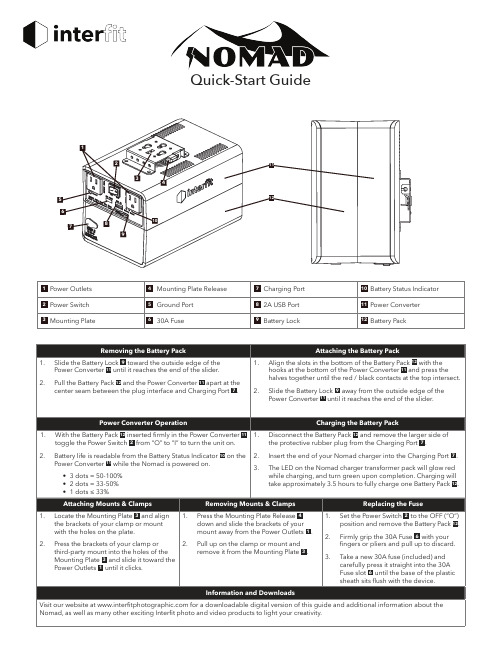
1. Locate the Mounting Plate 3 and align the brackets of your clamp or mount with the holes on the plate.
1. Press the Mounting Plate Release 4 down and slide the brackets of your mount away from the Power Outlets 1 .
Quick-Start Guide
1
2
11
3 4
5
12
6 7
8
10
9
1 Power Outlets 2 Power Switch 3 Mounting Plate
4 Mounting Plate Release 5 Ground Port 6 30A Fuse
7 Charging Port 8 2A USB Port 9 Battery Lock
2. Pull the Battery Pack 12 and the Power Converter 11 apart at the center seam between the plug interface and Charging Port 7 .
Attaching the Battery Pack
10 Battery Status Indicator 11 Power Converter 12 Battery Pack
Removing the Battery Pack
1. Slide the Battery Lock 9 toward the outside edge of the Power Converter 11 until it reaches the end of the slider.
- 1、下载文档前请自行甄别文档内容的完整性,平台不提供额外的编辑、内容补充、找答案等附加服务。
- 2、"仅部分预览"的文档,不可在线预览部分如存在完整性等问题,可反馈申请退款(可完整预览的文档不适用该条件!)。
- 3、如文档侵犯您的权益,请联系客服反馈,我们会尽快为您处理(人工客服工作时间:9:00-18:30)。
Quick Guide-AVL INDICOM目录一.执行预先定义的测量任务 (1)1.1 打开存在的参数文件 (1)1.2 执行并保存测量工作(连续测量模式) (2)二.建立新的测量项目 (5)2.1 创建参数文件 (5)2.1.1 设定发动机参数 (6)2.1.2 设置角码 (7)2.1.3 设置测量控制 (10)2.1.4 定义上止点 (11)2.1.5定义测量信号 (14)2.1.6 定义计算 (18)三.检查并保存参数 (19)3.1 执行并保存测量 (20)3.2 发动机监控 (20)四.举例 (20)4.1数据存取和数据管理 (20)4.1.1打开本地保存文件 (20)4.1.2通过数据管理器打开存储的文件 (22)4.1.3 在数据管理器中,使用数据源工作 (23)4.1.4 便捷的数据过滤方法 (25)4.1.5 同时打开多个文件 (26)4.2 显示例子 (27)4.2.1 图表窗口 (27)4.2.2 在存在的图表中加入数据集 (30)4.2.3 添加图表 (31)4.2.4 添加目标 (32)4.2.5 对于数据显示的拖放操作 (33)4.3 计算的例子 (34)4.3.1 显示数据的数学分析(曲线或图表形式) (34)4.3.2 使用计算器创建公式 (36)4.3.3 使用图形化公式编辑器创建公式(例子最大压力/最大压升率) (37)4.4 单位转换 (38)一.执行预先定义的测量任务1.1 打开存在的参数文件1. 点击菜单键的“打开”功能键,然后选择“打开参数文件”功能块。
2. 在对话框中出现默认文件夹中已保存的参数文件,以.xpa结尾。
选择文件petrol.xpa3. 点击打开,然后文件打开并显示在通道浏览器中。
1.2 执行并保存测量工作(连续测量模式)1. 在工作流程栏中点击开始采集功能键如果没有事先定义的显示窗口,那么Indicom将自动生成一个标准的图,在图中会包含所有的测量信号-在这个例子中包含了四条缸压曲线。
2. 再次点击该键停止数据采集。
3. 在工具栏中,点击Save Measurement Data按键就可保存测量数据。
对话框出现,会让你选择文件存放的位置并可为其重新命名,甚至可做出必要的评注。
这些测量文件就会以AVL的I-file格式存储。
∙你也可以通过菜单栏中的Extras | Pre-Sets Data Storage定义文件存放的位置。
默认存放位置是MyData | IFiles folder。
但在台架上连续的测量,我们推荐使用IndiCom文件夹以外的与项目有关的文件夹作为存放的位置。
∙在数据向导中,已在上述你可找到所存文件的文件夹中建立了一个数据源。
点击工作流程栏中测量&保存键(Measure & Save)当测量循环次数达到规定数量的时候,停止测量并自动保存数据。
在屏幕右下方就会看到循环条,你可通过滑动循环条浏览每个循环。
二.建立新的测量项目下面的教程与所使用硬件型号无关,这样可以不用考虑设备的水平。
所显示的对话框是基于AVL的671. 虽然其中的一些对话框与其他型号可能略有不同,但在所有类型设备的教程中的功能还是相同的,如有不同将会提出来。
如你使用自己系统中的教程,我们推荐链接AVL发动机模拟器,这样就可提供角标信号,当然也有四个缸压信号。
当然,你也可以在真实的发动机台架上研究教程。
这样,你可以在真实的台架上直接了当地针对实际的应用寻找相应地指导。
如你有离线软件,那么就可使用软件中的发动机模拟器来研究教程-教程中包含了相应的注释。
当然,对于一些功能,例如RTP计算或者是TDC计算,不能模拟或者在某种程度上不能模拟。
教程不需要任何先决条件就可以研究。
唯一需要就是文件正确地安装。
2.1 创建参数文件使用IndiPar去设定硬件参数或者完成测量步骤1)在工作流程栏中点击设置键,然后选择菜单中的Parameter Editor IndiParIndipar作为一个独立的窗口打开,在其中有菜单栏和工具栏。
在工作窗口的底部,可以观察到数据采集系统的图形。
IndiCom离线使用者注意:所显示的数据采集系统是源自所使用的硬件描述文件。
你可以在Extras | Change Offline Hardware中更改该描述。
尽管新的工作设置将删除当前布局,例如整体中的显示窗口,但是它不能删除当前的测量参数设置。
2)选择File | New Parameter File...菜单选项并且对"are-you-sure"回答YES。
2.1.1 设定发动机参数1. 在工作流程栏中点击发动机对话框有两页构成,可以分别点击2. 你可以输入发动机类型和气缸机械尺寸,并且为它定义一个名字。
3. 详细说明汽缸数IndiCom软件可以定义一位或两位数字的气缸数给所有信号,这样可使它们与各自的止点相关联。
如果在一个发动机上,定义多于一个气缸,那么非常重要的是所使用的数字与实际参与工作的气缸分配一致。
另一方面,如果所有的气缸并没有参与到测量中,或者气缸数量对应用并不重要,那么你可只设定显示的汽缸数。
请记住的是,要在第二个对话框定义点火顺序。
如你正使用AVL的发动机模拟器,那么你可以使用默认的汽缸数(4个)和几何尺寸。
4. 定义点火顺序也就是每个气缸上止点之间的角度。
IndiCom建议有时候需要修改标准值。
当使用发动机模拟器时这种调整是必要的,因为原来的点火顺序总是1-2-3-4。
一个个点击点火顺序栏然后通过下拉菜单去设定正确的点火顺序。
你可以保证在两个气缸间,止点角度是180度。
在发动机台架上,确定设置正确是非常重要的。
在离线模式中,如果你想将参数文件传送到台架上,那么设置是否正确也是非常重要的。
2.1.2 设置角码1. 点击工作流程栏中的CDM/TDC定义角度标志的对话窗将打开2. 设置角码在对话框中,你可以看到很多预先定义的硬件配置,从中可选择正在使用的设备型号,并且无论角标信号是事先通过外部倍增还是通过系统来倍增。
角标仪都可以不用外部转换器直接连接。
特殊的CDM1输入信号对于上述例子是适用的。
但如果你正使用外部倍增器,那么就必须使用CDM2。
AVL发动机模拟器会产生等同于调理过后的角码信号。
如果将角度标志转换成3600,那么就选择AVL 364/365 - via Converter (multiplied)。
当将角码设定为720(它就是没有经过处理的364/365传感器信号)且经过内部倍增到0.1度时,这样燃烧分析系统就不再通过自身进行倍增。
当你通过CDM1,将 364/365衬套直接连接到台架上,并且以0.1度精度进行工作时。
这两种设置都是非常必要的。
如果你在台架上使用不同角码,需要研读在线帮助章节。
它可以通过点击Help键或者按F1来获得。
3. 设定参考气缸和其上止点在同样的一个对话框中,你也不得不详细说明参考气缸及它的TDC值,或者就是说触发信号和TDC位置在角度上的距离。
这些参数通常由TDC测量工作来决定的,这种测量要么使用监控的缸压信号,要么是使用在参考气缸中所安装的电容性TDC传感器信号。
对于这个过程,由于需要定义测量信号,所以我们将会在以后继续讨论该话题。
检查信号同步当已经退出设定角标设置的对话框时,你可用运行的发动机或者是已连接的模拟器来检查设备角标的逻辑。
点击在工作流程栏中的Check键,然后选择SYNC-Check打开对话框,产生三个数字值。
∙每个循环的码数(在这个例子中是7200)∙最后所发生的同步错误-它是从定位点的值开始在一周内计算角码的偏差∙发动机的转速如果角标的数字和发动机转速不正确,那么这个角标就没有正确设定。
冻结参数你试图为同样一个发动机和测试台架创建更为详细的参数文件吗?如果是的话,请冻结你想重新使用的参数。
1.在工作流程栏上点击Engine图标2. 在性能页面,Engine Geometry激活了检查对话框,在其中可以选定Freeze engineparameters3.点击在工作流程栏中的CDM/TDC4.激活对话框,选择Freeze CDM / TDC parameters.当打开一个新的参数时,文件冻结的参数具有优先权。
当使用IFEM系列放大器时:1.右击进入硬件浏览功能块并从快捷菜单中选择Amplifier settings...2.激活Use settings saved in amplifiers2.1.3 设置测量控制1. 在菜单栏上的Parameter中点击Measurement Control该对话框可定义测量的模式。
为了达到教材所需的效果,在这里我们将不会列举通常的测量模式。
2. 检查要采集信号的类型- 角基:对于通常的测量在角基情况下,有两个选项原始数据(Raw Data)实时压力(RTP)通过激活其中任何一个选项框,你就可以最终定义在测量结束的时候,哪种数据可用。
通常,两种选项都激活。
如果取消实时压力选项(这个选项总是必要的,例如,对于冷启动试验),在实时模式中,结果值无法确定。
如果仅仅激活实时压力,由于原始数据不能保存,那么只能记录多次循环的特征值。
所以在教程中,激活原始数据(Raw Data)和实时压力(RTP)-时基3. 设定测量持续时间(通常是循环次数)其中,有两个两个选项:-连续采集缓存:可以设定在线或者是连续采集模式中缓存区的大小。
在该种模式下,得到的统计结果多少将取决于你所设定的缓存大小。
-测量持续时间:你所设定的循环次数对于每次测量后结束时,进一步的评估或者是存储是有效的。
在我们举例中,设定缓存为30个循环,100个循环为测量持续时间。
在测量控制对话框中的其他页面可以允许你作如下的工作:∙自动激活原始数据平均值∙定义自动相位校正∙创立随机测量条件∙通过使用完整的运行序列(脚本),载入常用测量过程对于这个教程,在其他对话页面上不需要做任何的改变。
2.1.4 定义上止点如果你正使用台架工作,那么参考缸的上止点位置就必须要设定。
1.在工作流程栏上点击CDM/TDC建议将1缸作为参考缸并保持如下设置2.在角标仪选项中,选择使用的角标仪和其分辨率或者通过New重新定义。
3.定义每个发动机循环触发器TDC Determination)。
选择测量的类型(AVL上止点传感器或者倒拖模式下的压力曲线)。
5.在Type中,你可以详细定义上止点是通过AVL的上止点传感器还是缸压传感器来得到的。
-------------------------------------------------------------------------------------------------------------------------------- 信息如果你选择倒拖模式下的缸压曲线,那么就要考虑热动力学损失角。