fluke说明书
福禄克fluke测温仪使用说明

福禄克fluke测温仪使用说明
1、仔细阅读说明书,了解、熟悉各功能键的作用及主要注意事项。
2、备好三节5号电池,按要求装入仪器。
3、在每次不同温度的环境中测量时,都要将仪器放置10分钟以上适应新环境。
4、确认仪器外表完好无损,掌握、了解仪器各功能键后进入测量程序。
5、温度单位设定为“℃”。
6、将仪器测量窗口在适当距离内(测量距离必须小于被测区域直径的4倍)对准被测工件,按动测量键(TEST键)即可从显示屏幕LCD读出被测物体的表面温度。
7、松开测量键后,必须保持本机姿势0.5秒。
8、如被测物体距离较远,可打开激光光束指示器,(设置方法,按住SET键进入“F-5”时选“1”时打开激光光束指示器功能选“0”时取消)按住测量键来瞄准。
9、测量时不要将本机的激光直接对准眼睛或通过反射性的表面(如镜面反射)照射眼睛。
10、使用过程中必须小心轻放,应避免放在过分潮湿高温或阳光直晒的地方。
11、长时间不使用,一定要将电池取出,在电池电量不足时及时更换新电池以免影响测量值的误差。
12、测试结束后,必须擦试镜片,不可用任何溶剂清洁镜片,可用压缩空气吹去灰尘后,用湿棉布或湿软布擦试。
13、装入仪器盒内。
fluke相序表说明书

fluke相序表说明书
Fluke相序表是一种用于检测三相电源相序的仪器。
以下是Fluke相序表的简要使用说明:
1. 开启电源:首先,打开Fluke相序表的电源开关。
2. 连接测试线:将测试线连接到Fluke相序表的对应端口上。
通常情况下,测试线一端为鳄鱼夹,可用于直接夹住电源线,另一端为插入式插头,可插入到Fluke相序表的对应插孔中。
3. 选择相序模式:根据需要检测的电源类型(如单相或三相),在Fluke相序表的面板上选择相应的模式。
4. 开始测试:按下Fluke相序表上的“运行”或“开始”按钮,仪器将开始检测电源的相序。
5. 读取结果:Fluke相序表将根据检测到的相序给出相应的指示。
例如,如果检测到正相序,仪器可能会显示绿灯;如果检测到逆相序,则可能会显示红灯。
6. 结束测试:完成相序检测后,关闭Fluke相序表的电源开关,并从电源和测试线上取下测试线。
7. 注意事项:在测试过程中,请确保电源处于断开状态或确保您有资格进行带电操作。
同时,避免在潮湿的环境中使用Fluke相序表。
为获得更准确的结果和确保仪器的正常工作,建议您遵循Fluke相序表的维护和保养建议。
同时,详细的使用说明和规格可能会因不同型号而有所不同,建议参考随仪器提供的用户手册或联系制造商以获取更准确的信息。
fluke绝缘电阻测量仪说明书

fluke绝缘电阻测量仪说明书交流传动系统调试时,必须使用绝缘电阻测试仪对变频器和电动机的主回路和控制回路分别进行绝缘测试,从而保证系统的安全运行。
福禄克Fluke1587绝缘电阻测试仪不仅对主回路进行快速测量,而且还能提供‘电阻档’功能对控制回路进行绝缘测试。
使用福禄克Fluke1587绝缘电阻测试仪进行变频器主回路(以VACONNXP产品为例)绝缘测量应遵循下列步骤:1.断开变频器所有与外界的接线,确保被测电路未连接任何电源。
然后将输入端L1,L2,L3和输出端U,V,W短接在一起2.将福禄克绝缘电阻测试仪的测试探头插入‘+,输入端子,然后将’另一端接到‘接地点’3.将探头与待测电路连接,绝缘电阻测试仪会自动检测电路是否通电。
如果电路中的电压超过30Vacordcjlj试被自动禁止。
4.选择福禄克Fluke1587绝缘电阻测试仪的‘Insulationtest’测试功能。
5.通过‘Range’按钮选择合适的测试电压(500Vdc)。
6.按住‘Insulationtest’测试键,读出绝缘电阻测试仪上所显示的阻抗值。
读数达到稳定可能需要几秒钟。
阻抗值越髙越好,此时读数为550兆欧,可以判断该绝缘良好。
7.继续将绝缘电阻测试仪的探头留在测试点上,然后释放‘Insulationtest’按钮。
被测电路即开始通过仪表放电,直至结束。
变频器控制回路(以VACONNXP产品为例)绝缘测量时应该注意的是必须用福禄克Fluke1587绝缘电阻测试仪带的‘电阻档’进行连续性测试,一般测试值>=1兆欧,表示绝缘良好。
使用绝缘电阻测试仪进行电动机绝缘测试时,应相对于接地线,分别测试U,V,W三相绕组线,一般测量值>=5兆欧,表示绝缘良好。
fluke万用表使用说明书
fluke万用表使用说明书中FLUKE 15B型和FLUKE 17B可以测量电压、电阻、电流、二极管、三极管、MOS场效应管的测量等几大功能综合在一起的强大的一款小仪器。
为了让你更好的掌握万用表测量方法,电工之家来详解一下它的使用方法和功能与注意事项。
一、测量电压时测量直流电压时,如电池、随身听电源等。
首先将黑表笔插进相印的孔,把旋钮选到相印位置。
二、测量交流电压的时表笔插孔与直流电压的测量一样,不过应该将旋钮打到交流档处所需的量程即可。
交流电压无正负之分,测量方法跟前面相同。
无论测交流还是直流电压,要注意自身安全,不要随便用手触摸表笔的金属部分。
三、测量电流时测量直流电流时。
将黑表笔插入对应孔。
将FLUKE 15B型和FLUKE 17B万用表串进电路中,保持稳定,即可读数。
四、测量电阻时用表笔接在电阻两端金属部位,测量中可以用手接触电阻,但不要把手同时接触电阻两端,这样会影响测量精确度,因为人体是电阻很大。
五、测量二极管时表笔位置与电压测量一样;用红表笔接二极管的正极,黑表笔接负极,这时会显示二极管OL。
再次对调表笔会显示一个数值。
再次调换表笔,显示屏显示“OL.”则为正常。
因为二极管的反向电阻很大,否则此管已被击穿或性能已经改变。
六、三极管的测量表笔插位同上;其原理同二极管。
先假定A脚为基极,用黑表笔与该脚相接,红表笔与其他两脚分别接触其他两脚;然后再用红笔接A脚,黑笔接触其他两脚,且此管为PNP管。
那么集电极和发射极如何判断呢?数字表不能像指针表那样利用指针摆幅来判断。
七、MOS场效应管的测量利用FLUKE 15B型和FLUKE 17B的二极管档。
若某脚与其他两脚间的正反压降均大于2V,即显示“1”,此脚即为栅极G。
再交换表笔测量其余两脚,压降小的那次中,黑表笔接的是D极(漏极),红表笔接的是S极(源极)。
在使用FLUKE 15B型和FLUKE 17B 的同时也要注意以下问题避免可能受到电击或人员伤害,以及避免对电表或待测装置造成损害,请遵照下面的惯例说明使用电表:①进行连接时,先连接公共测试导线,再连接带电的测试导线;切断连接时,则先断开带电的测试导线,再断开公共测试导线。
FLUKE福禄克系列示波器中文说明书上册

2011 年 5 月(Simplified Chinese)© 2011 Fluke Corporation. 版权所有。
荷兰印刷。
规格如有更改,恕不另行通知。
所有产品名称均为其所属公司的商标。
ScopeMeter 190 Series IIFluke 190-062, -102, -104, -202, -204, -502用户手册上 册有限保修及服务范围在正常使用与维修情况下,Fluke 保证每一产品均无材料和工艺问题。
自发货之日算起,测试工具保修期为三年,附件保修期为一年。
零配件及产品修理与维护的保修期为 90 天。
此保修仅限于原始购买者或 Fluke 指定经销商的产品使用客户;而不适用于保险丝和普通电池,或任何 Fluke 认为因错误使用、改装、疏忽或因事故或非正常条件下操作或处理而导致损坏的产品。
在 90 天内,Fluke 保证软件运行符合其功能规范,并且保证软件正确记录于完好无损的介质上。
Fluke 不保证软件毫无差错或无操作中断情况。
Fluke 指定经销商只能向产品使用客户对新的或未使用过的产品提供保修,而无权以 Fluke 的名义扩充或更改保修内容。
从 Fluke 指定的销售渠道或按相应国际价格购买的产品可以得到保修。
当产品在一个国家购买而要在另一个国家修理时,Fluke 保留向客户收取修理/更换零配件费用的权利。
对于在保修期内送回 Fluke 指定的维修中心,要求按原价退款或者免费维修或更换的有故障产品,Fluke 的保修义务是有限的。
要获得保修服务,请就近联系 Fluke 指定的维修中心,或在附上故障说明、邮费和预付保险(目的地交货价)后,将产品寄往最近的 Fluke 指定的维修中心。
Fluke 对运输中可能出现的损坏情况不承担责任。
产品在维修后,将寄回给客户,邮费预付(目的地交货价)。
如果 Fluke 确定产品故障是由于错误使用、改装、事故或非正常情况下使用或操作造成的,Fluke 将提供维修费用预算并在得到认可后方进行维修。
fluke使用说明书
福禄克FLUKE DTX系列(Dtx-1800,Dtx-1200,Dtx-lt)简单操作步骤说明:一、福禄克测试仪初始化步骤:1、充电:产品主机、辅机分别用电源适配器充电,直至电池显示灯转为绿色;2、设置语言:操作:将fluke dtx系列产品主机旋钮转至“SET UP”档位,按右下角绿色按钮开机;使用↓箭头;选中第三条“Instrument setting ”(本机设置)按“ENTER”进入参数设置,首先使用→箭头,按一下;进入第二个页面,↓箭头选择最后一项Language按“ENTER”进入; ↓箭头选择最后一项Chinese 按“ENTER”选择。
将语言选择成中文后才进行以下操作。
3、自校准:取fluke dtx系列产品Cat 6A/Class EA 永久链路适配器,装在主机上,辅机装上Cat 6A/Class EA 通道适配器。
然后将永久链路适配器末端插在Cat 6A/Class EA 通道适配器上;打开辅机电源,辅机自检后,“PASS”灯亮后熄灭,显示辅机正常。
“SPECIAL FUNCTIONS”档位,打开主机电源,显示主机、辅机软件、硬件和测试标准的版本(辅机信息只有当辅机开机并和主机连接时才显示),自测后显示操作界面,选择第一项“设置基准”后(如选错用“EXIT”退出重复),按“ENTER”键和“TEST”键开始自校准,显示“设置基准已完成”说明自校准成功完成。
二、设置福禄克测试仪基本参数操作:将fluke dtx系列产品主机旋钮转至“SET UP”档位,使用“↑↓”来选择第三条“仪器值设置”,按“ENTER”进入参数设置,可以按“←→”翻页,用“↑↓”选择你所需设置的参数,按ENTER 进入参数修改,用“↑↓”选择你所需采用的参数设置,选好后按ENTER选定并完成参数设置。
1、新机第一次使用需要设置的参数,以后不需更改。
(将旋钮转至“SET UP”档位,使用↓箭头;选中第三条:仪器设置值按ENTER进入如果返回上一级请按EXIT):1)线缆标识码来源:(一般使用自动递增,会使电缆标识的最后一个字符在每一次保存测试时递增一般不用更改)2)图形数据存储:(是)(否)通常情况下选择(是)3)当前文件夹:DEFAULT 可以按ENTER进入修改其名称(你想要的名字)4)结果存放位置:(使用默认值“内部存储器”假如有内存卡的话也可以选择“内存卡”)5)按→进入第2个设置页面,操作员:You Name 按ENTER 进入按F3删除原来的字符“←→↑↓”来选择你要的字符选好后按ENTER确定6)地点:Client Name,是你所测试的地点可以依照地e)小点进行修改7)公司:You Company Name,你公司的名字8)语言:Language,默认是英文9)日期:输入现在日期10)时间:输入现在时间11)长度单位:通常情况下选择米(m)2、新机不需设置采用原机器默认值的参数:1)电源关闭超时:默认30分钟2)背光超时:默认1分钟3)可听音:默认是4)电源线频率:默认50Hz5)数字格式:默认是6)将旋钮转至“SET UP”档位选择双绞线按ENTER 进入后NVP 不用修改7)光纤里面的设置,在测试双绞线是不须修改3、使用过程中经常需要改动的参数:将旋钮转至“SET UP”档位,选择双绞线,按ENTER进入:线缆类型:按ENTER进入后按↑↓选择你要测试的线缆类型例如我要测试超5类的双绞线在按ENTER进入后选择UTP 按ENTER ↑↓选择“Cat 5e UTP ” 按ENTER 返回。
Fluke 热成像设备说明书

Reliability matters.Image quality matters.Performance matters.UPTIME OR DOWNTIME YOUR RESULTS MATTER• F rees you from having to leave the site to send images and/or reports •S end reports wirelessly when they’re needed, where they’re needed• C omplete more inspections in a day • On-site analysis• G et instant feedback from others or next steps approved immediately• R eal-time report previewing— instant gratification • U ser interface is optimized for each mobile device (iOS, iPhone ® and iPad ®)SmartView ® MobileFluke CNX ™ Wireless System• Capture up to five additional measurements with CNX wireless modules • M ultiple tools report to your CNX enabled Fluke infrared camera • Q uicker readings means less time finding problems and more time solving them • Capture measurements from as far as 20-meters away• T he list of Fluke test tools that can connect wirelessly continues to growYOUR WORLD. YOUR TOOLS.CONNECTED.Sending a comprehensive report to a supervisor’s or customer’s mobile phone… Analyzing and reporting from the field without having to go back to the office… Multiple tools that report to you simultaneously… This is the world of SmartView ® Mobile app and CNX ™ Wireless System. Available only from Fluke—where your results matter.FOCUS is the single most important thing to ensure when conducting an INFRARED INSPECTION.Many inspection sites are difficult for certain auto focus systemsPassive auto focus systems often only capture the near-field subject, in this case the chain link fenceFluke LaserSharp ™ Auto Focus clearly captures what you want to inspect. Every. Single. Time. The red dot from the laser confirms what the camera is Without an in-focus image, temperature measurements may not be as accurate (sometimes as much as 20 degrees off) and you could miss a problem.Fluke provides customers with two superior focusing solutions—LaserSharp ™ Auto Focus (see page 5) and IR-OptiFlex ™ Focus System (see page 7) and still gives you the flexibility of using manual if you wish.Ti400 Ti300 Ti200Ti400Ti300Ti200ACCURACY MATTERSOptimized for Industrial, Electrical and Building ApplicationsA new generation of tools with next generation performance.Technology changes. The last thing we want is for you to feel like you’re missing out on critical innovations, so Fluke has engineered all three new infrared cameras to adapt to change. Being future-ready is part of their DNA. You can test and measure with wireless speed and ease, and connect with other wireless devices. If there’s an infrared camera in your future, make sure it’s one with a future.Your confidence level is about to go up a notch. With precision laser technology, you can focus on your target with pinpoint accuracy and know you’re getting the correct image and temperature measurements you need. Troubleshooting has never been easier. This isn’t hit-and-miss technology. This is point-and-shoot-and-get-it-right every single time performance.Fluke introduces the only infrared cameras withLaserSharp ™ Auto Focus for consistently in-focus images.EVERY . SINgLE. TIME.IR-PhotoNotes ™ Annotation SystemGet an exact reference to your problem area by capturing multiple photos per file. Add images of equipment, motor nameplates, workroom doors or any other useful or critical information.Multi-mode video recordingTroubleshoot with the industry’s only infrared camera that offers the proprietary IR-Fusion ® Technology and records focus-free video in visible light and infrared. Monitor processes over time, easily create infrared video reports, and troubleshoot frame-by-frame. Easily download to PCs for video viewing and analysis.Ti125TiR125Ti110TiR110Ti105TiR105Ti100Ti125Ti110Ti105Ti100TiR125TiR110TiR105SIMPLICITY MATTERSBuilding ApplicationsIndustrial/Electrical Fluke innovation makes it easier to do more in less time.EASY TO CHOOSE. EASY TO USE.HARD TO BEAT .When you’re budget-conscious (and who isn’t these days?), the fact that you can get Fluke quality at an affordable price means you can breathe a sigh of relief. At Fluke, ‘affordable’ doesn’t mean sacrificing quality to give you a lower price. It means we’ve found a way to give you the most camera for your money. In this case, a suite of the lightest, most rugged, easiest-to-use professional infrared cameras you can buy.IR-Fusion ® TechnologyEnjoy the industry’s only point-and-shoot IR-Fusion infraredcameras that provide five different user-selectable modes for greater clarity. Our patented technology blends digital and infrared images into a single image to precisely document problem areas. Fluke exclusive AutoBlend ™ Mode generates a partially transparent image to make problem detection and communication fast and easy.R ugged one-hand operationExperience the most rugged and reliable, lightweight professional infrared camera around. One-touch focus, laser pointer, and torch. Point-and-shoot simplicity and the ergonomic design details that matter.Electronic compassMake sure you and others know the location of the problem. Compass readings easily appear in images and reports.IR-OptiFlex ™ Focus SystemDiscover issues significantly faster with Fluke’s revolutionary, ultra-rugged focus system. The IR-OptiFlex ™ Focus System gives you optimum focus by combining focus-free ease-of-use with the flexibility of manual focus on the same camera!For more than 65 years, Fluke isDesigned better. Built tougher.Superior image qualityThere’s a reason Fluke is so passionate about image quality. Clearer, cleaner, crisper images result in better information and more informed solutions. The better the image, the better you look when you show the images to your managers and customers. Our newest models of infrared cameras are the only ones where you can find IR-Fusion ® Technology and LaserSharp ™ Auto Focus. The Ti400, Ti300 and Ti200 also come fully loaded with a 5 MP digital camera, a HDMI video output, and a 640x480 high resolution LCD display.Legendary ruggednessand reliabilityFluke has earned their reputation as a tool of choice for electrical, industrial and building professionals. Whatever the job andwherever you work, when there’s a Fluke infrared camera in your hand, you’re prepared for the worst and ready to do your best. Fluke infrared cameras are designed to withstand a 2 meter drop (6.5 ft) and engineered to resist water and dust (IP54 Rating) so that your camera works without compromise..5 m 1 m 1.5 m 5 ft3.25 ft1.6 ft2 m6.5 fthow qUALITY IS MEASUREDBecause your results matter ™.Ease of useOur customers would rather spend time preventing and solving issues—not figuring out how their infrared camera works. We’ve gained a few other insights after spending thousands of hours in the trenches with them. That time and knowledge has allowed our engineers to develop breakthroughs in design, like buttons you can use when you’re wearing work gloves, and simple-to-use, on-camera functions such as voice annotation, so that you don’t have to stop to take notes with pen and paper. More recent innovations include:•L aserSharp ™ Auto Focus to ensure the best focus every single time •C NX ™ Wireless System to allow your CNX test modules to communicate additional measurements to your camera •I R Fusion ® Technology with Auto Blend ™ Mode to more easily locate, understand and report what the problem could be • C onnectivity to wirelessly transfer images to your PC, Apple ® iPad ® and iPhone ®All of these innovations can help you quickly understand what the current state is, create a report, determine next steps or begin a preventive maintenance program; all while the factory and processes are still up and running.Innovation that works for youFluke engineers know you’re not interested in the bells and whistles other manufacturers like to tout, so they focus solely on features you really need to help you work better, faster, and smarter.The groundbreaking features that you’ve come toknow, like IR-Fusion ® Technology, AutoBlend ™ Mode, voice annotation, IR PhotoNotes ™ Annotation System, and now LaserSharp ® Auto Focus help you get better results faster and easier. Get into the best position possible to get the results that matter to you and your customers with SmartView ® Software and SmartView ® Mobile.Ti400Ti300Ti200Ti125 Product Specifications Optimized for Industrial, Electrical and Buildings InspectionsTemperature measurement range (not calibrated below -10 °C) -20 °C to +1200 °C(-4 °F to +2192 °F) -20 °C to +650 °C (-4 °F to +1202 °F)-20 °C to +350 °C(-4 °F to +662 °F)Detector type 320 x 240 pixels240 X 180 pixels200 X 150 pixelThermal sensitivity (NETD)≤ 0.05 °C at 30 °C target temp (50 mK) ≤ 0.075 °C at 30 °Ctarget temp (75 mK)Field of view24 ° x 17 °Spatial resolution (IFOV) 1.31 mRad 1.75 mRad 2.09 mRadCustomizable logo options Users can brand their infrared images with a Fluke logo,upload their own company logo or no logo.Primary focusing system LaserSharp™ Auto Focus IR-OptiFlex™ Focu Manual focus YesIR-Fusion® Technology YesCNX™ Wireless enabled (Availableas country certification areapproved—notifications made viaSmartView® Software)Voice annotation60 seconds maximum recording time per image; reviewable playback on imagerIR-PhotoNotes™Yes (5 images)Yes (3 images)Wi-Fi® connectivity Yes, to PC and Apple® iPhone® and iPad®Streaming video Via USB to PC and HDMI to HDMI compatible device Streaming USB-to-PCvideo outputMulti-mode video recording*Yes (fully-radiometric .IS3 and standard MPEG-encoded .AVI)Yes (fully-radiometric.IS3 and standard MPEG-encoded .AVI) M8-point cardinal compass* Yes YesRuggedized touchscreen display (capacitive)8.9 cm (3.5 in) diagonal landscape color VGA (640 x 480)LCD with backlightSoftware SmartView® full analysis and r Warranty11Ti110Ti105Ti100TiR125TiR110TiR105Optimized for Industrial and Electrical InspectionsOptimized for Building Inspections -20 °C to +250 °C (-4 °F to +482 °F)-20 °C to +150 °C (-4 °F to +302 °F)160 X 120 pixels≤ 0.10 °C at 30 °C target temp (100 mK)≤ 0.08 °C at 30 °C target temp (80 mK)22.5 °H x 31 ° V 3.39 mRad—™ Focus System Focus-free 1.2 m (4 ft) and beyondIR-OptiFlex ™ Focus SystemFocus-free 1.2 m (4 ft)and beyond—Yes——YesYes—60 seconds maximum recording time per image; reviewable playback on imager ——Yes (3 images)———Streaming USB-to-PCvideo output—Yes (Standard MPEG-encoded .AVI)——Yes (fully-radiometric.IS3 and standardMPEG-encoded .AVI)Yes (StandardMPEG-encoded .AVI)—Yes—YesYes——nd reporting software included with free download of SmartView ® Mobile app2 years, Instrument Care Plans are also available.* Features marked with an asterisk are coming soon in a firmware download from SmartView ® software.1.800.868.7495********************Fluke -Direct .caFor more information call:In the U.S.A. (800) 443-5853 or Fax (425) 446-5116In Europe/M-East/Africa +31 (0) 40 2675 200 or Fax +31 (0) 40 2675 222In Canada (800)-36-FLUKE or Fax (905) 890-6866From other countries +1 (425) 446-5500 or Fax +1 (425) 446-5116Web access: ©2013 Fluke Corporation.Specifications subject to change without notice.All trademarks are the property of their respective owners. Printed in U.S.A. 08/2013 2674264M_ENFluke CorporationPO Box 9090, Everett, WA 98206 U.S.A.Fluke Europe B.V.PO Box 1186, 5602 BD Eindhoven, The NetherlandsModification of this document is notpermitted without written permission from Fluke Corporation.Dedicated supportquestions? Call 1-800-760-4523 or contact us via our chat function on our website at /thermography to request your free product demonstration. We’ll be happy to answer your questions, ship a unit for you to test for a week or send out a representative if you need on-site support.Fluke accessoriesEnhance your infrared camera’s performance with Fluke accessories. Choose car chargers,additional smart batteries or smart battery chargers to keep you up and running in the field. For special applications select optional lenses, a visor for outside inspections or a tripod mounting accessory.Fluke also offers specialized instrument CarePlans—ask your Fluke representative or distributor for additional information.Fluke trainingGet additional information and training at the Fluke Training web page. Take advantage of free on-line seminars and for those who seek more advanced training and professional mentoring, contact our Fluke training partner, The Snell Group, the most respected name in infrared education.Fluke authorized training is provided by our partner,1.800.868.7495********************Fluke -Direct .ca。
fluke万用表使用说明书
fluke万用表使用说明书中FLUKE 15B型和FLUKE 17B可以测量电压、电阻、电流、二极管、三极管、MOS场效应管的测量等几大功能综合在一起的强大的一款小仪器。
为了让你更好的掌握万用表测量方法,电工之家来详解一下它的使用方法和功能与注意事项。
一、测量电压时测量直流电压时,如电池、随身听电源等。
首先将黑表笔插进相印的孔,把旋钮选到相印位置。
二、测量交流电压的时表笔插孔与直流电压的测量一样,不过应该将旋钮打到交流档处所需的量程即可。
交流电压无正负之分,测量方法跟前面相同。
无论测交流还是直流电压,要注意自身安全,不要随便用手触摸表笔的金属部分。
三、测量电流时测量直流电流时。
将黑表笔插入对应孔。
将FLUKE 15B型和FLUKE 17B万用表串进电路中,保持稳定,即可读数。
四、测量电阻时用表笔接在电阻两端金属部位,测量中可以用手接触电阻,但不要把手同时接触电阻两端,这样会影响测量精确度,因为人体是电阻很大。
五、测量二极管时表笔位置与电压测量一样;用红表笔接二极管的正极,黑表笔接负极,这时会显示二极管OL。
再次对调表笔会显示一个数值。
再次调换表笔,显示屏显示“OL.”则为正常。
因为二极管的反向电阻很大,否则此管已被击穿或性能已经改变。
六、三极管的测量表笔插位同上;其原理同二极管。
先假定A脚为基极,用黑表笔与该脚相接,红表笔与其他两脚分别接触其他两脚;然后再用红笔接A脚,黑笔接触其他两脚,且此管为PNP管。
那么集电极和发射极如何判断呢?数字表不能像指针表那样利用指针摆幅来判断。
七、MOS场效应管的测量利用FLUKE 15B型和FLUKE 17B的二极管档。
若某脚与其他两脚间的正反压降均大于2V,即显示“1”,此脚即为栅极G。
再交换表笔测量其余两脚,压降小的那次中,黑表笔接的是D极(漏极),红表笔接的是S极(源极)。
在使用FLUKE 15B型和FLUKE 17B 的同时也要注意以下问题避免可能受到电击或人员伤害,以及避免对电表或待测装置造成损害,请遵照下面的惯例说明使用电表:①进行连接时,先连接公共测试导线,再连接带电的测试导线;切断连接时,则先断开带电的测试导线,再断开公共测试导线。
福禄克网络测线仪使用说明书
FLUKE网络测试仪器说明书班级:330910姓名:***学号:********一、福禄克测试仪初始化步骤:1、充电:将Fluke dtx系列产品主机、辅机分别用电源适配器充电,直至电池显示灯转为绿色;2、设置语言:操作:将fluke dtx系列产品主机旋钮转至“SET UP”档位,按右下角绿色按钮开机;使用↓箭头;选中第三条“Instrument setting ”(本机设置)按“ENTER”进入参数设置,首先使用→箭头,按一下;进入第二个页面,↓箭头选择最后一项Language按“ENTER”进入; ↓箭头选择最后一项Chinese 按“ENTER”选择。
将语言选择成中文后才进行以下操作。
3、自校准:取fluke dtx系列产品Cat 6A/Class EA 永久链路适配器,装在主机上,辅机装上Cat 6A/Class EA 通道适配器。
然后将永久链路适配器末端插在Cat 6A/Class EA 通道适配器上;打开辅机电源,辅机自检后,“PASS”灯亮后熄灭,显示辅机正常。
“SPECIAL FUNCTIONS”档位,打开主机电源,显示主机、辅机软件、硬件和测试标准的版本(辅机信息只有当辅机开机并和主机连接时才显示),自测后显示操作界面,选择第一项“设置基准”后(如选错用“EXIT”退出重复),按“ENTER”键和“TEST”键开始自校准,显示“设置基准已完成”说明自校准成功完成。
二、设置福禄克测试仪基本参数操作:将fluke dtx系列产品主机旋钮转至“SET UP”档位,使用“↑↓”来选择第三条“仪器值设置”,按“ENTER”进入参数设置,可以按“←→”翻页,用“↑↓”选择你所需设置的参数,按ENTER进入参数修改,用“↑↓”选择你所需采用的参数设置,选好后按ENTER选定并完成参数设置。
三、福禄克测试仪测试过程:⒈根据需求确定测试极限值和电缆类型:通道测试还是永久链路测试?是CAT5E还是CAT6还是其他?⒉关机后将测试标准对应的适配器安装在主机、辅机上,如选择“TIA CAT5E CHANNEL”通道测试标准时,主辅机安装“DTX-CHA002”通道适配器,如选择“TIA CAT6A PERM.LINK”永久链路测试标准时,主辅机各安装一个“DTX-PLA002”永久链路适配器。
Fluke 电磁场测量仪用户手册说明书
LDR, LDGLaser DetectorsUsers ManualAugust 2016© 2016 Fluke Corporation. All rights reserved. Specifications are subject to change without notice.All product names are trademarks of their respective companies.LIMITED WARRANTY AND LIMITATION OF LIABILITYEach Fluke product is warranted to be free from defects in material and workmanship under normal use and service. The warranty period is three years and begins on the date of shipment. Parts, product repairs, and services are warranted for 90 days. This warranty extends only to the original buyer or end-user customer of a Fluke authorized reseller, and does not apply to fuses, disposable batteries, or to any product which, in Fluke's opinion, has been misused, altered, neglected, contaminated, or damaged by accident or abnormal conditions of operation or handling. Fluke warrants that software will operate substantially in accordance with its functional specifications for 90 days and that it has been properly recorded on non-defective media. Fluke does not warrant that software will be error free or operate without interruption.Fluke authorized resellers shall extend this warranty on new and unused products to end-user customers only but have no authority to extend a greater or different warranty on behalf of Fluke. Warranty support is available only if product is purchased through a Fluke authorized sales outlet or Buyer has paid theE applicable international price. Fluke reserves the right to invoice Buyer for importation costs of repair/replacement parts when product purchased in one country is submitted for repair in another country.Fluke's warranty obligation is limited, at Fluke's option, to refund of the purchase price, free of charge repair, or replacement of a defective product which is returned to a Fluke authorized service center within the warranty period.To obtain warranty service, contact your nearest Fluke authorized service center to obtain return authorization information, then send the product to that service center, with a description of the difficulty, postage and insurance prepaid (FOB Destination). Fluke assumes no risk for damage in transit. Following warranty repair, the product will be returned to Buyer, transportation prepaid (FOB Destination). If Fluke determines that failure was caused by neglect, misuse, contamination, alteration, accident, or abnormal condition of operation or handling, including overvoltage failures caused by use outside the product’s specified rating, or normal wear and tear of mechanical components, Fluke will provide an estimate of repair costs and obtain authorization before commencing the work. Following repair, the product will be returned to the Buyer transportation prepaid and the Buyer will be billed for the repair and return transportation charges (FOB Shipping Point).THIS WARRANTY IS BUYER'S SOLE AND EXCLUSIVE REMEDY AND IS IN LIEU OF ALL OTHER WARRANTIES, EXPRESS OR IMPLIED, INCLUDING BUT NOT LIMITED TO ANY IMPLIED WARRANTY OF MERCHANTABILITY OR FITNESS FOR A PARTICULAR PURPOSE. FLUKE SHALL NOT BE LIABLE FOR ANY SPECIAL, INDIRECT, INCIDENTAL OR CONSEQUENTIAL DAMAGES OR LOSSES, INCLUDING LOSS OF DATA, ARISING FROM ANY CAUSE OR THEORY.Since some countries or states do not allow limitation of the term of an implied warranty, or exclusion or limitation of incidental or consequential damages, the limitations and exclusions of this warranty may not apply to every buyer. If any provision of this Warranty is held invalid or unenforceable by a court or other decision-maker of competent jurisdiction, such holding will not affect the validity or enforceability of any other provision.Fluke CorporationP.O. Box 9090 Everett, WA 98206-9090 U.S.A.Fluke Europe B.V. P.O. Box 1186 5602 BD Eindhoven The Netherlands11/99Table of ContentsTitle Page Introduction (1)How to Contact Fluke (1)Safety Information (1)Product Familiarization (3)Use the Detector (6)Maintenance (7)Clean the Product (7)Batteries (8)Specifications (8)iLDR, LDGUsers ManualiiIntroductionThe LDR and LDG Laser Level Detectors (the Detector or Product) are battery-powered instruments that sense lasers difficult to see with the human eye. Use the Product with the 180LR or 180LG (the Laser Level) to identify new level and grade marks. The LDR senses a red laser. The LDG senses a green laser.How to Contact FlukeTo contact Fluke, call one of the following telephone numbers:•Technical Support USA: 1-800-44-FLUKE(1-800-443-5853)•Calibration/Repair USA: 1-888-99-FLUKE(1-888-993-5853)•Canada: 1-800-36-FLUKE (1-800-363-5853)•Europe: +31 402-675-200•Japan: +81-3-6714-3114•Singapore: +65-6799-5566•Anywhere in the world: +1-425-446-5500Or, visit Fluke's website at .To register your product, visit .To view, print, or download the latest manual supplement, visit /usen/support/manuals.Safety InformationA Warning identifies conditions and actions that pose hazards to the user; a Caution identifies conditions and actions that may damage the Product or the equipment under test.WarningFor safe operation and maintenance of theProduct and to prevent personal injury:•Read all safety information before you use the Product.•Carefully read all instructions.1LDR, LDG Users Manual2•Use the Product only as specified, or the protection supplied by the Product can be compromised.•Do not use the Product if it operates incorrectly.Table 1 is a list of the symbols used on the Product or in this manual.•Remove the batteries if the Product is not used for an extended period of time, or if stored in temperatures above 50 °C. If the batteries are not removed, battery leakage can damage the Product.Table 1. SymbolsLaser Detectors Product Familiarization3Product FamiliarizationFigure 1 and Table 2 show the features of the Product.Figure 1. Product FeaturesLDR, LDG Users Manual4Table 2. Product FeaturesItem DescriptionPower buttonPush to toggle on and off.Detection accuracy buttonPush to set detection accuracy level.On-Grade marksAlign with the laser on-grade reading andvertical mark notch.Beeper buttonPush to toggle the beeper on and off.Front LCDSee Table 3.Laser reception windowFace towards laser to detect beam.HolsterBeeper output signalFast - Detector is too low.Solid - Detector is on-grade.Slow - Detector is too high..Rear LCDFunctions the same as Front LCD. SeeT able 3.Rod clamp screw threadsAccepts the rod clamp screw to attach theclamp to the Product.Clamp guidesUse to align clamp.Offset notchUse to transfer reference marks 53.18 mmfrom the edge of the detector.Table 2. Product Features (cont.)Item DescriptionLaser Detectors Product Familiarization5Table 3 shows the indicators on the LCD.Table 3. LCD IndicatorsBattery doorRod clamp screwAttaches the clamp to the Detector.Alignment pointSecures and aligns the rod clamp to the detector in either a horizontal or a vertical position. Reference indicatorAlign with the on-grade marks on the Detector for grade rod readings.Clamp screw knobSecures clamp to measuring rod or staff.Table 2. Product Features (cont.)ItemDescriptionLDR, LDG Users Manual6Figure 2 shows how to attach the rod clamp to the Product.Figure 2. Rod Clamp AttachmentUse the DetectorUse the Detector and the Laser Level to identify new level and grade marks.To identify new level and grade marks:1.Put the bottom of the Laser Level on a stable surface ortripod.2.Connect the Detector to a measuring rod or staff.3.Turn on the Laser Level and the Detector and direct thelaser toward the laser reception window of the Detector. See Figure 3.4.Move the Detector up and down the rod until the laserlevel on the LCD indicates the Detector is level with the laser. If the beeper is on, the Detector also emits a solid output signal when the Detector is level with the laser.5.Secure the Detector to the rod and take measurementsas needed.NoteWhen the Laser Level is mounted on a tripod, make sure the tripod head is perfectly level. Errors in marks can result if a tripod is out of level.Laser Detectors MaintenanceFigure 3. Level and Detector MaintenanceThe Product does not require maintenance but treat Product as a calibrated instrument. Do not drop the Product. Clean the ProductClean the case with a damp cloth and a weak soap solution. Do not use abrasives, isopropyl alcohol, or solvents to clean the case or laser reception window.LDR, LDG Users ManualBatteriesReplace the batteries when the battery indicator shows a low battery.To install or replace the batteries (See Figure 4.):1.Remove the Product from the holster.2.Open the battery compartment.3.Install one 9 V batter with the correct polarity.4.Close the battery compartment.5.Put the Product back into the holster.Figure 4. Battery Replacement SpecificationsWorking Range..................≥6 m to ≤60 mAccuracyFine.................................0.75 mmMedium...........................1.75 mmPowerBatteries..........................1 x 9 V Alkaline IEC LR61Battery Life......................≥30 hrs, continuous use Dimensions(H x W x L).........................94 mm x 94 mm x 42 mm Weight................................0.20 kgTemperatureOperating........................-18 °C to +50 °CStorage...........................-40 °C to +70 °Cwith battery: -20 °C to +50 °C Relative Humidity..............0 % to 90 % (0 °C to 35 °C)0 % to 75 % (35 °C to 40 °C)0 % to 45 % (40 °C to 50 °C) AltitudeOperating........................2000 mStorage...........................12 000 m Safety.................................IEC 61010-1: Pollution Degree 2Laser DetectorsSpecificationsElectromagnetic Compatibility (EMC)International...................IEC 61326-1: Industrial ElectromagneticEnvironmentCISPR 11: Group 1, Class AGroup 1: Equipment has intentionally generated and/or usesconductively-coupled radio frequency energy that is necessary for theinternal function of the equipment itself.Class A: Equipment is suitable for use in all establishments other thandomestic and those directly connected to a low-voltage power supplynetwork that supplies buildings used for domestic purposes. Theremay be potential difficulties in ensuring electromagnetic compatibilityin other environments due to conducted and radiated disturbances.Korea (KCC)...................Class A Equipment (Industrial Broadcasting &Communication Equipment)Class A: Equipment meets requirements for industrialelectromagnetic wave equipment and the seller or user should takenotice of it. This equipment is intended for use in businessenvironments and not to be used in homes.USA (FCC).....................47 CFR 15 subpart B. This product isconsidered an exempt device per clause15.103.LDR, LDG Users Manual。
fluke说明书[1]
![fluke说明书[1]](https://img.taocdn.com/s3/m/7b07d69151e79b896802267c.png)
福禄克F430系列三相电能质量分析仪更快、更安全、更详细地定位和诊断的电能质量故障技术参数福禄克公司的F434 和F433三相电能质量分析仪可以帮助用户定位、预测、防止和诊断配电系统的故障。
对于那些维护或排障三相配电系统的工作人员来说,这些简便易用的手持工具是“必不可少”的。
新的IEC和GB国标关于闪变和电能质量方面的标准使得在对系统进行电能质量分析监测时有了判断的依据。
●记录三相系统中所有电能质量的参数。
●直观的菜单,最大程度上减少所需的设置。
●工业现场使用最高的安全等级。
●四个电压通道和四个电流通道。
●同时在所有相线上捕获波形数据。
●系统监测:在一个仪表板上现实全部电能质量参数。
●自动显示瞬态尖峰脉冲信号:不会漏掉任何一个事件。
●自动趋势绘图(AutoTrend)功能:无需对记录进行设置!●坚固的手持式设计。
●使用镍氢(NiMH)电池组时,一次充电可使用7个小时。
●将数据文件传输到PC,用于编写报告和利用FlukeView®软件进行分析。
CAT IV 600 V 和CAT III 1000 V的安全等级在设计时就考虑了保护用户和设备免受高压电击,福禄克F430系列电能质量分析仪、附件和充电器都经过验证,满足CAT IV 600 V和CAT III 1000 V环境下使用的严格的安全标准。
它们是同类别中第一款符合CAT IV安全等级的工具,所以可以被用于低压配电系统中所有的电气连接和插座。
快捷地观察趋势图利用AutoTrend(自动趋势绘图)功能,可以快速地深入浏览电能质量参数随时间的变化。
所显示的每一读数都被自动并且连续的进行记录,而不必设置触发限值或间隔时间,也无需手动启动记录过程。
可以快速地观察所有相线和零线上电压、电流、频率、功率、谐波或闪变的趋势图;还可以使用光标和缩放功能分析趋势-而不会中断记录。
AutoTrend功能在后台自动记录显示的所有参数。
在数据和趋势图之间切换,以及使用光标和缩放功能分析测量结果,都不会中断记录过程。
FLUKE DSX-5000简单操作说明书
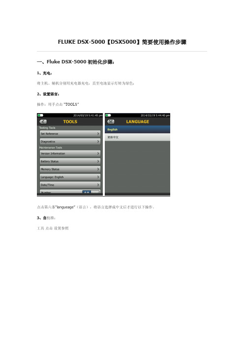
FLUKE DSX-5000【DSX5000】简要使用操作步骤一、Fluke DSX-5000初始化步骤:1、充电:将主机、辅机分别用充电器充电,直至电池显示灯转为绿色;2、设置语言:操作:用手点击“TOOLS”点击第六条“langueage”(语言),将语言选择成中文后才进行以下操作。
3、自校准:工具点击设置参照取Cat6A/Class EA永久链路适配器,装在主机上,辅机装上Cat6A/Class EA通道适配器。
然后将永久链路适配器末端插在Cat6A/Class EA通道适配器上;打开辅机电源,辅机自检后,“PASS”灯亮后熄灭,显示辅机正常。
打开主机电源,点击“工具”,显示设置参照、诊断、版本信息、电池状态、内存状态、语言、时间日期等。
点击“设置参照”按测试(或者白色TEST按钮)开始自校准,显示“已完成设置参照”说明自校准成功完成。
二、Fluke DSX-5000设置参数:操作:点击工具,用手拖动选择要修改参数。
按上面图标返回。
1、新机第一次使用需要设置参数,以后就不需要更改了。
2、电池状态:显示电量。
3、时间:输入现在的日期时间格式。
4、长度:选择M或者FT。
(通常国内为M)5、超时期限:选择背光时间,和电源关闭时间。
6、可听见的音频:开就可以听见声音,关闭则无。
7、电源频率:50Hz,60Hz。
8、显示屏:设置显示屏亮度。
三、Fluke DSX-5000设置参数:1、根据需求确定测试标准和电缆类型:通道测试还是永久链路测试?是CAT5E还是CAT6还是其他?2、关机后将测试标准对应的适配器安装在主机、辅机上,如选择“TIA Cat6Channel”通道测试标准时,主机安装“DSX-CHA004”通道适配器,如选择“TIA Cat6PERM.LINK”永久链路测试标准时,主辅机各安装一个“DSX-PLA004S”永久链路适配器。
3、新建一个测试项目;点击项目,出现项目栏目,点击出现测试设置,点击电缆类型。
Fluke 温度仪说明书

Temperature Panel and Benchtop Meters1⁄8DIN Size with LCD DisplayModel BS6000ASingleThermocouple Input$495Model BS6050Single RTD Input$495Model BS6051Six-Channel RTD Selectable$595Specifications for DP5000A and BS6000 SeriesInputs:Thermocouples: J, K, T, E, N, R, S; RTD Pt100, 2-, 3-, or 4-wire, Alpha 0.00385,Thermistor: 2252 Ωat 25°C (77°F).Display: 4-digit, backlit LCD Accuracy:±0.15% of rdg + 0.2°C at orabove 0°C (+0.4°F) at or above 32°F)±1°C below 0°C (±2°F below 32°F)Resolution:0.1°to 999.9°; 1°above 1000°Temperature Coefficient:0.01% of rdg/°CCold Junction Compensation: 0.0075°C/°C (0.0135°F/°F)Ambient Temperature : 0 to 50°C (32 to 122°F)Storage Temperature:-40 to 50°C (-40 to 122°F)Humidity: 0 to 70% non-condensing Power : 110 Vac (standard),Optional 230 Vac or 9 to 30 Vac/dcM-101ߜEasy-to-Read Backlit LCD ߜ°C/°F Switchable ߜ0.1°/1°Auto Ranging ߜThermocouple Selectable by Rear Panel SwitchesߜFront Panel Splash-Proof (IP65)ߜCan Be Used with OS36, OS37, and OS38 Infrared Probes ߜOptional RS-232ߜBenchtop Portable Meters ߜRugged ABS Case ߜAvailable as Single- or Six-Input ModelsDimensions:DP5000A, DP5050, DP5060:96 x 48 x 120 mm (3.78 x 1.89 x 4.72")BS6000A, BS6050, BS6060:118 x 57 x 150 mm (4.65 x 2.24 x 5.90")BS6001A,BS6051, BS6061:148 x 67 x 190 mm (5.83 x 2.64 x 7.48")Weight:DP5000A, DP5050, BS5060: 255 kg (0.56 lb)BS6000A, BS6050, BS6060: 500 g (1.1 lb)BS6001A, BS6051, BS6061: 850 g (1.87 lb)The DP5000A and BS6000 series of temperature panel and benchtop meters are both highly versatile and accurate. Available in thermocouple and infrared inputs, thermistor and RTD versions with 0.1 degree resolution, auto ranging to 1 degree above 1000°. The thermocouple versions are switch selectable for one of six thermocouple types from the rear panel. The DP5000A series is micro-processor driven andfully self-calibrating, offering exceptional accuracy and long term stability. The backlit LCD is easy to read in any light conditions from dim to bright sunlight, or fluorescent lighting.To Order (Specify Model Number)Model No.Price DescriptionDP5000A $245T/C input panel meter with infrared sensor input*DP5050245RTD input panel meterDP5060245Thermistor input panel meterBS6000A*495Benchtop meter: 1 T/C and OS36, OS37 OS38 input BS6001A*595Benchtop meter: 6 T/C and OS36, OS37 OS38 inputs BS6050495Benchtop meter: 1 RTD input BS6051595Benchtop meter: 6 RTD inputBS6060495Benchtop meter: 1 thermistor input BS6061595Benchtop meter: 6 thermistor inputsMDP5000A Series$245ShownModel OS36-K-50 probe, $185See Section JShown smaller than actual sizeModel NumberPriceDescriptionDP5000-BRACKETS $7Replacement panel bracketsDP5000-SBRACKETS7Panel brackets with adjustable screwsAccessoriesModel NumberPriceDescription-9/30N/C 9 to 30 Vac/Vdc -230N/C230 VacPower OptionsOrder SuffixPriceDescription-C2$40RS-232 communicationsCommunications OptionsInputRangeIron-Constantan-200 to 1200˚C -328 to 2192˚F CHROMEGA ®- ALOMEGA ®-200 to 1372˚C -328 to 2502˚F CHROMEGA ®- Constantan -200 to 1000˚C -328 to 1832˚F Copper - Constantan-200 to 400˚C -328 to 752˚F Platinum - 10% Rhodium/ Platinum -50 to 1767˚C -58 to 3212˚F Platinum - 13% Rhodium/ Platinum -50 to 1767˚C -58 to 3212˚F OMEGA-P ®- Nicrosil -200 to 1300˚C -328 to 2372˚FOMEGA-N ®- NisilInput Ranges for DP5000 and BS6000 Series* Can be used with OS36-K-50and OS36-K-440. Also will work with OS37and OS38units with either 20:1 or 100:1 fields of view. Comes complete with power cord, mating connector(s), operators’ manual. OMEGACARE SM extended warranty program is available for models shown on this page. Ask your sales representative for full details when placing an order.Ordering Example: BS6050-C2,single RTD input benchtop thermometer and RS-232 communications, $495 + 40 = $535. OCW-1 OMEGACARE SM extends standard 3-year warranty to a total of 4 years ($53), $535 + 53 = $588J K E T S R NCANADA www.omega.ca Laval(Quebec) 1-800-TC-OMEGA UNITED KINGDOM www. Manchester, England0800-488-488GERMANY www.omega.deDeckenpfronn, Germany************FRANCE www.omega.frGuyancourt, France088-466-342BENELUX www.omega.nl Amstelveen, NL 0800-099-33-44UNITED STATES 1-800-TC-OMEGA Stamford, CT.CZECH REPUBLIC www.omegaeng.cz Karviná, Czech Republic596-311-899TemperatureCalibrators, Connectors, General Test and MeasurementInstruments, Glass Bulb Thermometers, Handheld Instruments for Temperature Measurement, Ice Point References,Indicating Labels, Crayons, Cements and Lacquers, Infrared Temperature Measurement Instruments, Recorders Relative Humidity Measurement Instruments, RTD Probes, Elements and Assemblies, Temperature & Process Meters, Timers and Counters, Temperature and Process Controllers and Power Switching Devices, Thermistor Elements, Probes andAssemblies,Thermocouples Thermowells and Head and Well Assemblies, Transmitters, WirePressure, Strain and ForceDisplacement Transducers, Dynamic Measurement Force Sensors, Instrumentation for Pressure and Strain Measurements, Load Cells, Pressure Gauges, PressureReference Section, Pressure Switches, Pressure Transducers, Proximity Transducers, Regulators,Strain Gages, Torque Transducers, ValvespH and ConductivityConductivity Instrumentation, Dissolved OxygenInstrumentation, Environmental Instrumentation, pH Electrodes and Instruments, Water and Soil Analysis InstrumentationHeatersBand Heaters, Cartridge Heaters, Circulation Heaters, Comfort Heaters, Controllers, Meters and SwitchingDevices, Flexible Heaters, General Test and Measurement Instruments, Heater Hook-up Wire, Heating Cable Systems, Immersion Heaters, Process Air and Duct, Heaters, Radiant Heaters, Strip Heaters, Tubular HeatersFlow and LevelAir Velocity Indicators, Doppler Flowmeters, LevelMeasurement, Magnetic Flowmeters, Mass Flowmeters,Pitot Tubes, Pumps, Rotameters, Turbine and Paddle Wheel Flowmeters, Ultrasonic Flowmeters, Valves, Variable Area Flowmeters, Vortex Shedding FlowmetersData AcquisitionAuto-Dialers and Alarm Monitoring Systems, Communication Products and Converters, Data Acquisition and Analysis Software, Data LoggersPlug-in Cards, Signal Conditioners, USB, RS232, RS485 and Parallel Port Data Acquisition Systems, Wireless Transmitters and Receivers。
Fluke 网络自动测试器用户指南说明书

LinkRunner ®ATNetwork AutoTesterThe LinkRunner ® AT offers user-configured auto-tests for a wide range of important tasks. This network tester’s quick cable test and switch identification facilitates fast problem isolation. Test results can be automatically uploaded to the Link-Live results management cloud service to improve collaboration between network engineers and technicians, creating greater job visibility, project control, and fleet management.• Discover nearest switch name and port information via CDP/LLDP/EDP and verify link speed/duplex and connectivity to TCP/IP network with AutoTest • Validate up to 30W 802.3af/at PSE with TruePower™ loaded Power-over-Ethernet (PoE) test • Verify twisted-pair cable length and wire-map in a snap• AutoTest verifies and documents PoE, nearest switch, DHCP, DNS and Gateway service, and key devices connectivity in one go • Automate reporting and enable collaboration with result upload and management via Link-Live Cloud ServiceOverviewDATA SHEETLinkRunner AT is available in two models: LRAT-2000 and LRAT-1000. LinkRunner AT 2000 adds the following exclusive features:• Fiber support* • TruePower™ PoE Power Test up to 30W*• IPv6 support* • Reflector support* • More result storage: 50 instead of 10* • Uses Li-ION rechargeable battery instead of AA battery packKey FeaturesLeft: LRAT-2000 / Right: LRAT-1000*These exclusive features cannot be added to the LinkRunner AT 1000.Users can easily find opens, shorts, miswires, and split pairs in three different ways:• On non-terminated cable• With a WireView Cable Identifier• Check patch cord with the built-in wiremap port on the side of the LinkRunner ATCable LocationLocate cable runs with toning, switch port advertisement, switch port link light blinking, and remote cable identifiers. Toning supports both analog and digital IntelliTone modesThe LinkRunner AT uses the IEEE Link Layer Discovery Protocol (LLDP), along with the Ciscoand Extreme Discovery Protocols (CDP and EDP) to display the nearest switch model, slot, portand VLAN configured.The LinkRunner AT displays the following critical nearest switch information:• Switch name and model • Chassis, slot and port • Switch IP address•Voice and Data VLAN IDs• Duplex and speed (actual and advertised)• Signal Strength• Connection (MDI or MDI/X)• PoE voltage and power (actual and test limit)• Graphical representation of power on pairsThe LinkRunner AT features a packet reflector mode that allows the device to be used remotely during end-to-end network path performance tests to validate LAN and WAN throughput capabilities, up to 1Gbps. The reflector mode can be configured to swap MAC and/or IP addresses. LinkRunner AT 2000 supports packet reflection for:• EtherScope™ nXG Portable Network ExpertTruePower™ PoE Testing - Power Over Ethernet TestingLinkRunner AT features the ability to validate TruePower delivery before installing cameras, APs, and phones to ensure a smooth deployment. Quickly validate PoE performance by drawing actual power up to the 802.3at standard 25.5W. Load the circuit to stress switches, cabling and patch panels, all while measuring the voltage and pairs being used.IP V4/V6 AddressingValidate the IPv4 DHCP auto-negotiation process, subnet and DHCP server and verify IPv6 Link-Local and Global addressing.Switch informationCable wiring validationPacket Reflector ModePoE SetupAutoTest ResultsKey Service and Device ConnectivityLinkRunner AT can perform either a Ping or a TCP port open test to verify connectivity. The testconducted will reveal connection and response time to the default Gateway, preferred DNS server,and alternate DNS server. LinkRunner AT can connect to as many as 10 user-defined target devices,servers or services, testing using Ping, or a user-defined TCP port number. If a URL is used as thetarget, results will include response time and an IP address.802.1x AuthenticationVerify access to secure networks using 802.1x and MAC Access Control Lists (ACL). The includedLinkRunner AT Manager Software can be used to enable 802.1x and download certificates. AutoTest ResultsConfiguration SettingsAIRCHECK-G2-3YS 3 year AllyCare Support for AIRCHECK-G2, AIRCHECK-G2-KIT, AIRCHECKG2-TA-KT, ACKG2-LRAT2000 (covers ACKG2 only) and LR-G2-ACKG2-CBO (covers ACKG2 only)SpecificationsGeneralDimensions 3.5 in x 7.8 in x 1.9 in (8.9 cm x 19.8 cm x 4.8 cm)Weight18 oz (0.5 kg)Battery LRAT-1000 - 4 AA alkaline batteriesLRAT-2000 - Removable, rechargeable lithium-ion battery pack (18.5 Watt-hrs) Battery Life Typical operating life is 6 hours; Typical charge time is 3 hoursExternal AC Adapter/Charger AC input 90 to 264V AC 48 to 62 Hz input power DC output 15V DC at 1.2 Amps Display 2.8 in color LCD (320 x 240 pixels)Keypad12-key elastomericTone Generator IntelliTone™ digital tone: [500 KHz]; analog tones: [400 Hz, 1 KHz]Media Access; Copper RJ-45: 10BASE-T, 100BASE-TX, 1000BASE-T and PoE (IEEE 802.3af and 802.3at) Media Access; Fiber SFP Adapter Port supports 100BASE-FX and 1000BASE-LX/ SX/ZX (LRAT-2000 Only) Cable Tests Pair lengths, opens, shorts, splits, crossed, straight through, and cable IDPower over Ethernet (PoE)Single ended testing:- User-defined testing to IEEE 802.3at class 0, 1, 2, 3, 4 without LLDP negation, or 4 with LLDP negotiationThe following PSE PoE parameters are measured:- Pairs used- Received class- PSE type- Unloaded voltage(V)- Loaded voltage (V) (LRAT-2000 with TruePower™)- Unloaded power (W) (LRAT-1000)- Loaded power (W) (LRAT-2000 with TruePower™)EnvironmentalOperating Temperature 32°F to 113°F (0°C to +45°C)NOTE: The battery will not charge if the internal temperature of the tester is above 122°F (50°C).Operating relative humidity (% RH without condensation)90% (50°F to 95°F; 10°C to 35°C) 75% (95°F to 113°F; 35°C to 45°C)Storage temperature-4°F to 140°F (-20°C to +60°C)Shock and vibration Random, 2 g, 5 Hz-500 Hz (Class 2) 1 m dropSafety EN 61010-1 2nd editionSafety (LR-AT 2000 only)EN/IEC 60825-1:2007, EN/IEC 60825-2:2004+ A1:2007 (LRAT- 2000 only)Altitude4,000 m; Storage: 12,000 mEMC IEC 61326-1: Basic Electromagnetic Environment; CISPR 11: Group 1, Class A LinkRunner Manager SoftwareSupported OperatingSystems Windows® Vista, Windows® XP, Windows® 7, Windows® 8, Windows® 10Processor400 MHz Pentium processor or equivalent (minimum); 1 GHz Pentium processor or equivalent (recommended)RAM96 MB (minimum); 256 MB (recommended)Hard Disk Up to 500 MB of available space may be requiredDisplay1024 x 768 high color, 32-bit (recommended)Certifications and ComplianceSpecifications continued/products/linkrunner。
福禄克FLUKE过程校准仪使用说明书
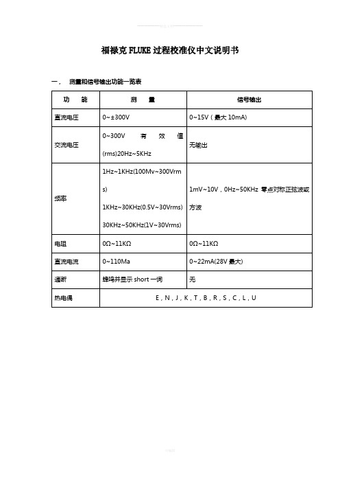
福禄克FLUKE过程校准仪中文说明书一,测量和信号输出功能一览表热电阻2,3,4线测量2线输出100ΩPlatinum(3926) 100ΩPlatinum(385) 120ΩNickel(672) 200ΩPlatinum(385) 500ΩPlatinum(385) 1000ΩPlatinum(385) 10ΩCopper(427) 100ΩPlatinum(3916)压力27种压力模块从2.5kPa至69,000kPa*回路电压24或28V(22mA最大)*对于压力输出功能,是指由外部手动压力泵或其它压力源作为压力信号二、初识校准仪1.当你第一次取出校准仪,你需要将电池充电见图9,给电池充电2小时。
2.将电池放入校准仪中。
3.连接校准仪的电压输出端和输入端如下:连接最左端的一对插孔(V、Ω、RTD输出)和最右端的一对插孔(VMEAS)(见图3)。
图3 跨接线连接图4 输入输出的例子4.开机按⊙,按▲,▼以调整对比度。
以达到最好的显示效果。
校准仪在接通电源时是直流电压的测量功能,可以在一对VMEAS输入插孔中得到读数。
5.按看到其测量情况。
6.按V—…键,选择直流电压输出。
按数字键5和ENTER=开始输出5.0000V直流电压。
7.量直流电压。
你将在上半部屏幕看到测量读数,在下半部屏幕看到输出值,如图4所示。
三、操作功能1.输入和输出插孔图5所示,校准器输入和输出插孔,表2解释它的用途。
表2 输入/输出插孔和连接器7,8!SOURCE(输出)mA测量mAΩRTD插孔输出或测量电流、电阻和RTDS插孔,并提供回路电源9,10!SOURE(输出)V ΩRTD插孔输出电压、电阻、频率、和模拟RTDS输出插孔图5 输入/输出插孔和连接2.按键校准仪按键如图6所示,表3解释它们的功能,有4个未带标记的兰色按键,在显示屏幕下面称之为功能键。
其功能在操作过程中屏幕出现的定义所确定。
功能键和其显示内部在本手册中用黑体字标明,例如:Choices图6 按键表3 键的功能序号性能说明15V-键测量方式中选择直流电压,输出方式中选择直流电压16开关键电源开关3.显示屏幕图7为典型的显示屏幕。
Fluke全优系列红外热像仪产品说明书
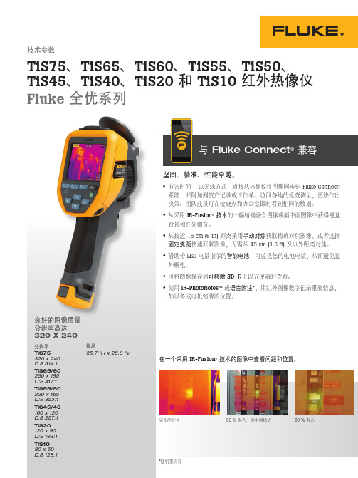
坚固、精准、性能卓越。
• 节省时间 – 以无线方式,直接从热像仪将图像同步到 Fluke Connect ® 系统,并附加到资产记录或工作单。
访问各地的检查测量,更快作出决策。
团队成员可在检查点和办公室即时看到相同的数据。
• 从采用 IR-Fusion ® 技术的一幅精确融合图像或画中画图像中获得视觉背景和红外细节。
• 从接近 15 cm (6 in) 距离采用手动对焦获取精确对焦图像,或者选择固定焦距快速获取图像,无需从 45 cm (1.5 ft) 及以外距离对焦。
• 借助带 LED 电量指示的智能电池,可监视您的电池电量,从而避免意外断电。
• 可将图像保存到可移除 SD 卡上以方便随时查看。
• 使用 IR-PhotoNotes™ 或语音附注*,用红外图像数字记录重要信息,如设备或电机铭牌的位置。
B与 Fluke Connect ® 兼容*随机型而异技术参数TiS75、TiS65、TiS60、TiS55、TiS50、 TiS45、TiS40、TiS20 和 TiS10 红外热像仪Fluke 全优系列良好的图像质量 分辨率高达 320 X 240分辨率TiS75320 x 240 D:S 514:1TiS65/60 260 x 195D:S 417:1TiS55/50 220 x 165D:S 353:1TiS45/40160 x 120 D:S 257:1TiS20120 x 90D:S 193:1TiS1080 x 60视场35.7 °H x 26.8 °V在一个采用 IR-Fusion ® 技术的图像中查看问题和位置。
完全的红外50 % 混合,画中画模式50 % 混合*Fluke Connect® SmartView® 分析和报告软件在所有国家/地区均有提供,而 Fluke Connect 并非如此。
有关是否提供,请咨询您的授权 Fluke 经销商。
Fluke 产品说明书

The Digital Ground Resistance T ester Model 3640 performs ground resis-tance measurement. This direct reading tester measures from 10mΩto 1999Ωand is Auto-Ranging, so it automatically seeks out the optimum measurement range. Easy to use – simply connect the leads, Press-to-Measure and read. The large LCD (nearly 3/4" high) is easy to read, and also indicates low battery status, overrange and lead reversals. The Model 3640 comes with 3 color-coded terminals to aid in easy hookup.Three LED indicators on the front panelcontinuously warn the user of anymeasurement problems to ensureaccurate and reliable tests.The Model 3640 is fuse protected upto >250V AC to protect the instrumentagainst voltage into the test leads. Inthe event of a system fault, it can with-stand 250V AC with spikes of 3000V ACor 1000V DC.The heavy duty ABS case is O-ringsealed against dust and water and thePress-to-Measure button is also sealed.Model 3640 is battery powered, forconvenient use in remote field applica-tions. Mechanical and safety specifica-tions, such as vibration and drop test,meet or exceed IEC standards,toensure safe and reliable field use.Ground Resistance T ester Model 3640is a rugged, easy-to-use instrumentideal for maintenance crews performingnumerous tests. The Model 3640 isdesigned to reject high levels ofinterference, therefore it can be usedunder difficult conditions such as highstray currents that normally affectmeasurement accuracy.Ground Resistance Tester Model 3640 & 3640 KitsModel 3640 shown instandard soft carrying caseCatalog #2114.92T est Kit for 3-Point testing includes instrument,two 150 ft color-coded leads on spools (red and blue), one 30 ft lead (green),two 14.5" T -shaped auxiliary ground electrodes,one set of five spaded lugs, 100 ft tape measurerand carrying bag.Catalog #2135.13Ground KitsFeatures•Fall-of-Potential method•Measures ground resistance (2- and 3-Point)•Auto-Ranging: automatically selects the optimum range•Designed to reject high levels of noise and interference•Extremely simple to operate: connect – press – read•LED on faceplate informs operator of high input noise, high auxiliary rod resistance and fault connections•Battery powered•Rugged dustproof and rainproof field case•Color-coded terminals•May also be used for continuity tests on bonding •Double Insulation •CE MarkApplications•Three-point measurements for measuring resistance to ground of ground rods and grids. Three-point measurements are generally used when the electrode or grid is easily disconnected, if corrosion issuspected, or where ground faults are unlikely to occur.•Two-point tests for continuity tests on bonding or on pre-established grounds. This test is commonly performed in urban environments where proper auxiliary electrode placement may be obscured by confined real estate. Measurements are referenced against a good local ground conductor.T est Kit for 4-Point testing includes instrument, two 300 ft color-coded leads on spools (red and blue), two 100 ft color-coded leads (green and black), four 14.5" T -shaped auxiliary ground electrodes, one set of five spaded lugs, 100 ft tape measurer and carrying bag.Catalog #2135.14T est Kit for 4-Point testing includes instrument, two 500 ft color-coded leads on spools (red and blue), two 100 ft color-coded leads (green and black),one 30 ft lead (green), four 14.5" T -shaped auxiliaryground electrodes, one set of five spaded lugs,100 ft tape measurer and carrying bag.Catalog #2135.15Accuracies and specifications are given for an ambient temperature of 23°C ±3°K, RH of 45 to 55%, battery power at 8V, auxiliary resistance at the measurement terminals <200Ω, no stray voltage and a magnetic field from 0 to 40Å/m.ORDERING INFORMATION CATALOG NO.Ground Resistance Tester Model 3640 (3-Point Digital). . . . . . . . . . . . . . . . . . . . . . . . . . . . . . . . . . . . . . . . . . . . . . Cat.#2114.92Includes batteries, soft carrying case and user manualGround Resistance Tester Model 3640 Kit . . . . . . . . . . . . . . . . . . . . . . . . . . . . . . . . . . . . . . . . . . . . . . . . . . . . . . . . Cat.#2135.13Test Kit for 3-Point testing includes meter, two 150 ft color-coded leads on spools (red and blue), one 30 ft lead (green), two 14.5" T-shaped auxiliary ground electrodes, one set of five fork terminals, 100 ft tape measurer and carrying bag Ground Resistance Tester Model 3640 Kit . . . . . . . . . . . . . . . . . . . . . . . . . . . . . . . . . . . . . . . . . . . . . . . . . . . . . . . . Cat.#2135.14Test Kit for 4-Point testing includes two 300 ft color-coded leads on spools (red and blue), two 100 ft color-coded leads (green and black), four 14.5" T-shaped auxiliary ground electrodes, one set of five fork terminals, 100 ft tape measurer and carrying bag.Ground Resistance Tester Model 3640 Kit . . . . . . . . . . . . . . . . . . . . . . . . . . . . . . . . . . . . . . . . . . . . . . . . . . . . . . . . Cat.#2135.15Test Kit for 4-Point testing includes two 500 ft color-coded leads on spools (red and blue), two 100 ft color-coded leads (green and black), one 30 ft lead (green), four 14.5" T-shaped auxiliary ground electrodes, one set of five fork terminals, 100 ft tape measurer and carrying bag. Accessories (Optional)25ΩCalibration Checker . . . . . . . . . . . . . . . . . . . . . . . . . . . . . . . . . . . . . . . . . . . . . . . . . . . . . . . . . . . . . . . . . . . . . . . . Cat. #2130.59T ape Measure (100 ft). . . . . . . . . . . . . . . . . . . . . . . . . . . . . . . . . . . . . . . . . . . . . . . . . . . . . . . . . . . . . . . . . . . . . . . . . . Cat. #2130.60Ground T ester Video/Workbook set. . . . . . . . . . . . . . . . . . . . . . . . . . . . . . . . . . . . . . . . . . . . . . . . . . . . . . . . . . . . . . . . Cat. #2130.64Input terminalsLarge LCD with low battery indicatorLED measurement faultindicators:X-Z FaultXv-Y Hi ResistanceXv-Y Hi NoisePress-to-MeasurebuttonConstruction。
- 1、下载文档前请自行甄别文档内容的完整性,平台不提供额外的编辑、内容补充、找答案等附加服务。
- 2、"仅部分预览"的文档,不可在线预览部分如存在完整性等问题,可反馈申请退款(可完整预览的文档不适用该条件!)。
- 3、如文档侵犯您的权益,请联系客服反馈,我们会尽快为您处理(人工客服工作时间:9:00-18:30)。
Simplified Chinese May 2012, Rev. 3 8/2015©2012-2015 Fluke Corporation All product names are trademarks of their respective companies.MultiFiber ™Pro 光功率仪及光纤测试套件入门指南有限担保和责任限制福禄克网络 (Fluke Networks) 公司保证其主机产品从购买之日起一年内,在材料和工艺均无任何缺陷,除非另有说明。
如无另外规定,部件、零配件、产品修理和服务的保证期为 90 天。
Ni-Cad(镍镉),Ni-MH(镍氢)和 Li-Ion(锂离子)电池、电缆或其它外围设备均被视作部件或零配件。
本项保证不包括因意外、疏忽、误用、改装、污染及非正常情况下的操作或处理而造成的损坏。
经销商无权以Fluke Networks的名义给予其它任何担保。
欲在保修期内取得保修服务,请与您最近的Fluke Networks授权服务中心联系,以获取有关产品退还的授权信息,并将有故障的产品连同故障说明寄至该服务中心。
如需获取授权经销商列表,请访问/ wheretobuy。
本项保证是您唯一的赔偿。
除此以外,Fluke Networks不做任何明示或隐含的保证(例如适用于特定目的的隐含保证)。
Fluke Networks对基于任何原因或推测的任何特别的、间接的、偶发的或后续的损坏或损失概不负责。
由于某些州或国家不允许将隐含保证或偶发或后续损失排除在外或加以限制,故上述的责任限制或许对您不适用。
4/15Fluke NetworksPO Box 777Everett, WA 98206-0777USA目录使用用户手册 (1)安全须知 (1)联系 Fluke Networks (1)仪表及光源的功能 (2)电池的安装、寿命及状态 (3)仪表显示屏功能 (4)光源显示屏功能 (6)用户参数 (7)极性探测 (8)自动波长功能 (8)如何清洁 MTP/MPO 连接器 (9)如何测量光功率 (9)如何测量损耗 (10)设置基准 (10)设置极限值 (12)测量损耗 (12)内存功能 (14)iMultiFiber Pro 入门指南ii1使用用户手册本指南提供基本信息以帮助您开始使用MultiFiber ™ Pro 仪表和光源。
有关详细信息,请参阅 Fluke Networks 网站上提供的最新版本《MultiFiber Pro 用户手册》。
安全须知警告为了避免危害辐射可能对眼睛造成伤害,切勿直视光学连接器内部(请参见第 2 页)。
有些光源会产生肉眼看不见的辐射,可能对您的双眼造成永久的损伤。
小心为避免损坏光纤连接器,避免数据丢失,以及确保最准确的测试结果,在每次使用前,用适当的清洁步骤对所有的光纤连接器进行清洁。
不使用时,请用保护罩盖住所有的连接器。
使用仪表或光源之前请阅读《MultiFiber Pro 用户手册》上的其他安全信息。
联系 Fluke Networkssupport@1-800-283-5853, +1-425-446-5500Fluke NetworksPO Box 777Everett, WA 98206-0777USAFluke Networks 的业务经营遍及全球 50 多个国家或地区。
欲知更多的联系信息,请访问我们的网站。
MultiFiber Pro 入门指南仪表及光源的功能GUE05.EPS :开关键。
:软按键。
各按键的功能显示在该按键的上方。
:仪表:按 键选择功率测量或损耗测量模式。
要访问测试设置的菜单及VIEW RECORD(查看记录)模式,按住 键 2.5 秒。
光源:要查看光源的模式,请按住 键 2.5 秒。
带有自动闭合保护罩的 MTP/MPO 连接器。
小心要获得正确的测量值,请仅将 APC 连接器连接至单模光源。
仅将非 APC 连接器连接至多模光源。
您可以将APC 或非 APC 连接器连接至仪表。
2电池的安装、寿命及状态 用于将测试记录上传至 PC 的 USB 端口。
也可以使用该端口来安装更新的软件。
电池的安装、寿命及状态仪表和光源上电池至少可以工作 30 小时。
34MultiFiber Pro 入门指南仪表显示屏功能GUE03.EPS仪表的模式和测试的设置。
要选择 POWER (功率)、SETREF (设置基准)或 LOSS (损耗)测量模式,请按 键。
要更改测量的设置或查看记录,请按住 键 2.5 秒,然后使用 键和 键来进行选择。
∙POWER (功率):使用此模式来测量光功率。
参见第 9 页上的“如何测量光功率”。
∙SET REF (设置基准):使用此模式来设置损耗测量的基准值。
参见第 10 页上的“设置基准”。
∙LOSS (损耗):使用此模式来测量损耗。
参见第 12 页上的“测量损耗”。
∙LOSS LIMIT (损耗极限):使用此模式为损耗测量设置极限值。
参见第 12 页上的“设置极限值”。
∙VIEW RECORD (查看记录):使用此模式来查看及删除已保存的结果。
参见第 14 页上的“内存功能”。
仪表显示屏功能:测量有问题,或者试图保存测量值时内存已满。
OK:所有测量值均合格,或者仪表保存了结果。
POLARITY(极性):仪表和光源之间连接的极性:∙A、B、C:连接采用标准方法 A、B 或 C。
参见用户手册。
∙POLARITY ?(极性?):未使用标准方法连接、一根或多根光纤未连接或光源上的SCAN ALL(全面扫描)已关闭。
∙UNIV:当模块采用康宁 Plug & Play™ 通用系统极性管理方法时显示。
2 kHz:仪表探测 2 kHz 的调制光信号。
此功能帮助您识别接线板上的光纤。
SAVE(保存):显示SAVE(保存)时,可以按 键来保存功率或损耗测量值,或者基准值。
:当您可以使用 键或 键在选项或更改设置间进行滚动时,显示箭头图标。
CHANNEL(信道):当您测量功率或损耗时,按 键在信道的测量值之间进行滚动。
:当光源不是自动波长模式时,按 键以更改波长。
DELETE(删除):在VIEW RECORD(查看记录)模式下,使用 DELETE(删除)键来删除所选的记录或所有记录。
参见第 14 页上的“内存功能”。
损耗(dB)及功率测量值(mW、µW、dBm)的数字显示(带单位)。
REF(基准):当您保存基准值时显示。
参见第 10 页上的“设置基准”。
:信道指示器。
当光源的SCAN ALL(全面扫描)功能开启时,信道指示器将位于您所选的信道上。
当光源的SCAN ALL(全面扫描)功能关闭时,指示器将停留在光源所选的信道上。
仪表测量功率或损耗时,信道的序号依次闪烁。
56MultiFiber Pro 入门指南进度条为各个信道的损耗或功率测量显示相关的值。
功率测量,参见9。
损耗测量,参见第14页。
波长的数值显示。
:电池电量低时,低电量图标闪烁。
当光源传输一个波长识别符,并且仪表为了与光源保持一致而更改其波长设置时,显示 AUTO (自动波长)。
当只显示 时,必须按仪表上的 键来选择正确的波长。
参见第第 8 页上的“极性探测”页。
:当仪表通过 USB 端口与 PC 相连时,将显示此图标。
光源显示屏功能GUE04.EPS光源模式(如要查看菜单,请按住 2.5 秒):SCAN ALL ON (全面扫描开启):光源自动更改信道。
用户参数∙SCAN ALL OFF(全面扫描关闭):按 键或 键来更改信道。
∙AUTO ON(自动波长开启):光源传输一个MultiFiber Pro 仪表可读的波长识别符。
∙AUTO OFF(自动波长关闭):光源不传输波长识别符。
∙MODE2 kHz(2 kHz 模式):输出一个 2 kHz 的调制光信号。
用此模式来识别接线板上的光纤。
显示活动的信道。
CHANNEL(信道):当SCAN ALL(全面扫描)为OFF (关闭)时,按 键或 键来更改信道。
波长的数值显示。
:电池电量低时,低电量图标闪烁。
用户参数1关于仪表:确保仪表处于功率或损耗测量模式。
关于光源:确保光源处于信号输出模式。
2同时按住 键和 键 2.5 秒。
3要更改设置,请按 键。
或者若显示 ,则按 键。
4要查看下一个设置,请按 键。
5要保存设置并退出设置模式,按住 键和 键 2.5 秒。
MultiFiber Pro 入门指南极性探测您可以使用 MultiFiber Pro 仪表和光源来查看 MTP/MPO 跳线和电缆的极性。
来自光源的信号含有信道序号。
仪表将传输的序号与收到信号的信道序号进行比较。
然后仪表能够显示连接的极性。
参见第 5 页上的 项目。
自动波长功能来自光源的信号含有一个识别符,它告知仪表测量哪个波长。
除非光源处于 2 kHz 模式,否则它将传输自动波长信号。
当您选择 2 kHz 模式时,光源的 AUTO 自动波长)设置自动变更为 OFF (关闭)。
开启或关闭背光灯。
若在所选的分钟时长内未按下任何按键,则仪表和光源自动关闭。
要禁用此功能,选择破折号 ( )。
仅仪表:月( ),日( ),年( ),小时( )和分钟( )。
与保存的测量值一起仪表还列入日期和时间。
小时为 24 小时格式。
要在保存的记录中查看日期和时间,在 LinkWare PC 软件中查看记录。
:软件版本号。
:仅仪表。
工厂校准日期。
如何清洁 MTP/MPO 连接器如何清洁 MTP/MPO 连接器连接前,始终清洁并检查光纤连接器的端面。
Fluke Networks 建议您使用机械式清洁器,如 Fluke Networks IBC ™ OneClick Cleaner 清洁连接器。
如何测量光功率功率测量显示来自光源(如光网络接口卡或光学测试设备)的光功率值。
要测量功率1清洁并检查所有的连接器。
2在仪表上,按 键显示 POWER (功率)。
3如第10页所示进行连接。
4在仪表上,根据需要,按 键来选择光源的波长。
5要查看下一个信道的功率测量值,按 CHANNEL(信道)键。
进度条显示各个信道上功率级之间的差异(以 dB 为单位),以及所有 12 个信道的最大功率:仪表定期找到最大功率值并根据需要调整进度条。
6要保存测量值,确保仪表已经扫描过所有的 12 个信道,然后按 SAVE (保存)键。
仪表简略显示记录编号和 OK 。
所示的记录编号对应电缆内的 12 号光纤。
最大没椭圆形MultiFiber Pro 入门指南功率测量的连接如何测量损耗损耗测量显示在链路的光纤及连接器上丢失了多少光功率。
设置基准为了获得最准确的测试结果,应在以下时刻设置基准:∙每天刚开始的时候。
∙每当将测试导线与光源重新连接的时候。
∙每当看见负的损耗测量值时。