FS1570 FS2570操作说明书
FURUNO 备件价格参考

Furuno USA and Furuno Electric Company have developed fly away service kits for many of our Deep Sea Products. This Service Advisory identifies the part numbers for these kits, the spares contained in the kits, and it also explains how the program works.1) Fly away service kits are available to our Elite Dealers only. 2) Order the required kit(s) using the attached list.3) Freight charges to the dealer, the price of the kit, and a $100.00 service fee will be charged to your account when the kit is shipped to you. The dealer is also responsible for the return freight charges to Furuno USA.4)Upon return of the kit to Furuno USA, we will credit the price of the kit to your account. You will then be charged for all parts used or opened from the service kit. If the part you used is on our exchange program, you will be charged the exchange price after our service department inspects the faulty part. Any parts found to be missing from the kit will be considered to have been used and will be charged as well.5)All items in the fly away kits are in sealed bags. If those bags are opened we reserve the right to invoice you for the cost of the part, since it can no longer be considered new.Use the link below to view a complete list of our fly away service kits. Then, click on a specific product to see a list of the parts contained in the fly away service kit.Click here to see a complete list of fly away kits, as well as their contents.If you have any questions, you may visit our website ( ) and click on “Support,” then “Ask Furuno a Question.” You may also contact a Furuno support technician at either our Camas, WA facility, (360) 834-9300 or at our Denton, MD facility, (410) 479-4420.Best Regards,Pete ProvostHigh Seas Service ManagerMay 8, 200603-06TRelease DateRelease No.4400 N.W. PACIFIC RIM BLVD . •? CAMAS, WA 98607-9408 • TEL: (360) 834-9300 • FAX: (360) 834-9400 • Furuno Fred Says:Furuno USA has fly away service kits for many of our products, check out the list below. Click on a kit to see a list of the parts contained in the kit.FS5000 SSB RadiotelephoneVR5000 Voyage Data RecorderFR21x0 Radar DisplayFR28x5 Radar DisplayFAR2800 Radar DisplayFAR2800 Radar TransceiversAA50 Watch ReceiverCH250 SonarCH270 SonarDS30 Speed LogDSC6 Digital Selective Calling UnitFAR2xx7 Radar TransceiversFAR2xx7 Radar ProcessorFAR28x5 Radar S-Band T/RFAR28x5 Radar X-Band T/RVR5000 Service Tool KitVR5000 Annual Survey Too ls KitDS30 & DS50 Doppler Speed Log.DS80 Doppler Speed LogFA100 AISFAP2000 AutopilotFAR2xx7 Series RadarsFAR28x5 Series Radar sFEA2107 ECDISFEA2105 ECDISFelcom 11 Standard C InmarsatFelcom 12 Standard C InmarsatFelcom 15 Standard C InmarsatFelcom 70 Fleet 77 InmarsatFelcom 80 Inmarsat BFelcom 81 Inmarsat BFelcom 82 Inmarsat BFR21x5 Series Radar sFS1570 FS2570 SSB RadiotelephoneVR5000 Vessel Data RecorderFly Away Spares Kit B.O.M.VR5000 Fly Away Service KitPart Number for kit = FAS-KVR-5S0Case 1 of 1 part number FAS-KVR-5S0Ck Quanity Part Number Description List Price Exchange Price 1000-148-578Breaker (for main AC) 3130F120H7TW01Q-3A$155.00No Exchange 1000-148-579Breaker (for main DC) 3130F120H7TW01Q-10A$130.00No Exchange 1000-148-580Breaker (for BBU) 3130F120H7TW01Q-16A$130.00No Exchange 2000-148-647AC/DC power supply SP200-27$315.00No Exchange 1000-148-648Acoustic Beacon Pinger$1,695.00No Exchange 1000-148-939Main PCB 582-001 (3000002)$1,795.00T.B.A.1000-148-940SIG PCB 582-002 (300003)$3,795.00T.B.A.1000-148-941PWR PCB 582-003 (3000004)$1,895.00T.B.A.1000-148-942LED PCB 582-004 (3000001)$375.00No Exchange 1000-149-594Breaker (for main DC) ETA1110F112-P1M1 10A$140.00No Exchange 1000-149-595Breaker (for BBU) ETA1110F112-P1M1-16A$140.00No Exchange 1000-149-596Breaker (for main AC) ETA1110F112-P1M1-3A$145.00No ExchangeNOTE: PLEASE COMPLETE AN INVENTORY OF THIS KIT IMMEDIATELY UPON RECEIPT ANDREPORT ANY DISCREPANCIES. FAILURE TO DO SO WILL RESULT IN YOUR COMPANY BEINGBILLED APPROPRIATE TESTING AND/OR REPLACEMENT COSTS FOR ANY MISSING/UNSEALED/ DAMAGED MATERIALS UPON RETURN OF THIS KIT. PLEASE REPACK PROPERLY.6/7/2005FS5000 Fly Away Service KitPart Number for kit = FAS-KFS-512 & FAS-KFS-522Case 1 of 2 part number FAS-KFS-512Ck Quanity Part Number Description List Price Exchange 1005-594-20005P0347 CPU pcb$463.00$215.00 1005-594-22005P0348 RX pcb$2,419.00$625.00 1005-594-56005P0356 AF pcb$761.00$240.00 1005-594-71005P0359 Ant BK Relay pcb$535.00No Exchange 1005-927-25005P0354 I/F 24 Vots pcb$612.00$240.00 1005-927-460LM24008M LCD Assembly$467.00No Exchange 1005-927-61005P0360 Dummy Load$671.00No Exchange 1005-943-04005P0352Z/353Z/398Z Regulator Assembly$2,149.00$475.00 1005-943-07005P0349 ZEXC pcb$2,037.00$405.00 1005-943-08005P0414 Ref Osc pcb$472.00$185.00Case 2 of 2 part number FAS-KFS-522Ck Quanity Part Number Description List Price Exchange 1005-559-54005P0355 CPU pcb$1,098.00$310.00 1005-594-30005P0358-44 Coupler pcb (New Style)$2,767.00$475.00 1005-594-52005P0357 Key pcb$502.00$200.00 1005-943-02005P0363 PA/ Regulator Assembly$4,777.00$850.00 1005-927-24005P0350 TX Filter pcb$1,345.00$379.00 NOTE: PLEASE COMPLETE AN INVENTORY OF THIS KIT IMMEDIATELY UPON RECEIPT ANDREPORT ANY DISCREPANCIES. FAILURE TO DO SO WILL RESULT IN YOUR COMPANY BEINGBILLED APPROPRIATE TESTING AND/OR REPLACEMENT COSTS FOR ANY MISSING/UNSEALED/ DAMAGED MATERIALS UPON RETURN OF THIS KIT. PLEASE REPACK PROPERLY.13 December 2110FAS-KS1-570FS1570 FS2570 Fly Away Service KitQ Part Number Description Used With List Exchange Price 1000-056-946Control Unit FS2570C FS1570 FS2570$4,475.00Not Exchangeable 1000-056-948Handset HS2001FS1570 FS2570$315.00Not Exchangeable 1005-948-42005P0528A Coupler pcb FS1570 FS2570$1,810.00$695.00 1005-952-00005P0731 T-I/F pcb FS1570 FS2570$485.00Not Exchangeable 1005-952-01005P0732 T-CPU FS1570 FS2570$775.00$375.00 1005-952-02005P0751 DSP pcb FS1570 FS2570$370.00Not Exchangeable 1005-952-03005P0733 TX-RX FS1570 FS2570$1,350.00$525.00 1005-952-04005P0746 Preselect pcb FS1570 FS2570$190.00Not Exchangeable 1005-952-05005P0747 Ref OSC FS1570 FS2570$155.00Not Exchangeable 1005-952-06005P0734 W/R FS1570 FS2570$550.00Not Exchangeable 1005-952-07005P0744 Relay FS1570 FS2570$200.00Not Exchangeable 1005-952-10005P TX-Fil pcb FS1570$560.00Not Exchangeable 1005-952-11005P0737 SW-REG pcb FS1570 FS2570$200.00Not Exchangeable 1005-952-12005P0738 DRV pcb FS2570$480.00Not Exchangeable 1005-952-13005P0739 PA pcb 250w FS2570$850.00$390.00 1005-952-14005P0735 PA pcb 150w FS1570$515.00Not Exchangeable 1005-952-15005P0740 COMB pcb FS2570$250.00Not Exchangeable 1005-953-06005P0736A TX-FIL pcb FS2570$560.00Not Exchangeable 1005-958-53005P0610 w/heat sink 250 w FS2570$570.00Not Exchangeable 1005-958-54005P0543 w/heat sink 150 w FS1570$415.00Not Exchangeable NOTE: PLEASE COMPLETE AN INVENTORY OF THIS KIT IMMEDIATELY UPON RECEIPT ANDREPORT ANY DISCREPANCIES. FAILURE TO DO SO WILL RESULT IN YOUR COMPANY BEING BILLED APPROPRIATE TESTING AND/OR REPLACEMENT COSTS FOR ANY MISSING/UNSEALED/ DAMAGED MATERIALS UPON RETURN OF THIS KIT. PLEASE REPACK PROPERLY.FR2105 Radar Series Fly Away Service KitPart Number for kit = FAS-KR2-112 & FAS-KR-122Case 1 of 2 part number FAS-KR2-112Ck Quanity Part Number Description List Price Exchange 1008-517-56003P9232 IF pcb$522.00No Exchange 1008-517-57003P9243 RFC pcb$398.00No Exchange 1008-517-58003P9243B RFC pcb$345.00No Exchange 1008-517-59003P9244 MD pcb$464.00No Exchange 1008-517-60003P9244B MD pcb$410.50No Exchange1 008-517-630 03P9253 S P U pcb $2,571.50 $940.001008-487-64014P0298 RP pcb$1,682.10$729.00 1ARP2618P9002B ARP-26 pcb$2,695.00No ExchangeCase 2 of 2 part number FAS-KR2-122Ck Quanity Part Number Description List Price Exchange 2008-517-71003P9245D 220 VAC Power Supply Assembly$1,034.00$565.00 1000-631-715D8G-516 24 RPM Scanner Motor 24 vdc$600.00No Exchange 1000-136-566D8G-571 42 RPM Scanner Motor 24 vdc$1,975.00No Exchange 2008-487-340RTR-062 MIC Assembly TBA2008-487-350RTR-063 MIC Assembly TBA13 December 2110FLYKITVR5000USED ID P/N DESCRIPTION Qty LIST EA.1ACER AL1714 17" LCD MONITOR12COMPAQ PRESARIO R3000 LAPTOP s/n CND3520SY4138 PORT POWER STRIP14DC/DC P/S FOR FIREWIRE AMP15AC P/S FOR LAPTOP PC (Black)16AC P/S FOR MONITOR (White)17VIDEO CABLE FOR MONITOR18CAMERA BAG CONTAINING THE FOLLOWING ITEMS19FIRE WIRE/PCMCIA Adapter110FIRE WIRE CABLE 4PIN-6PIN RED (NLA replaced with above)111FIRE WIRE CABLE 6PIN -6PIN ORANGE112EITHERNET X-OVER CABLE ORANGE113VR-5000 INFO CD ROM114US-EURO AC PLUG ADAPTOR11564MB COMPACT FLASH CARD / VR-5000 SOFTWARE V.2.09 116CD with VR-5000 & LivePlayer software1* with addendumNOTE: PLEASE COMPLETE AN INVENTORY OF THIS KIT IMMEDIATELY UPON RECEIPT AND REPORT ANY DISCREPANCIES. FAILURE TO DO SO WILL RESULT IN YOUR COMPANYBEING BILLED APPROPRIATE TESTING AND/OR REPLACEMENT COSTS FOR ANYMISSING/DAMAGED/UNSEALED MATERIALS UPON RETURN OF THIS KIT.***ANY OPENED ITEMS WILL BE CONSIDERED "USED" AND CHARGES******WILL BE ASSESSED FOR THAT ITEM.***PLEASE TAG ALL USED ITEMS WITH A "P101" TAG.PLEASE REPACK PROPERLY********** PRICES SUBJECT TO CHANGE WITHOUT NOTICE ********** Revised 4/27/2005FLYKITVDRANNUALID P/N DESCRIPTION Qty LIST EA.$1FUS-AVD-R01Gateway Laptop Computer Model 450SX4 s/n 002818842212,000.00$2FUS-AVD-R02Gateway Power Supply Model PA-1900-05150.00 3FUS-AVD-R03Set of 3 keys for VR-50001Priceless$4FUS-AVD-R04Dukane Pinger Test Set, Model 42A12D, s/n US1833271695.00 5FUS-AVD-R05ver 3.18 software mod kit (CD, CF program card, caps, IC & Memory)11,250.00$$6FUS-AVD-R06Firewire hub with power cable179.95$7FUS-AVD-R07 6 Pin > 6 Pin Firewire cable19.95$8FUS-AVD-R08 4 Pin > 6 Pin Firewire Cable19.95 9FUS-AVD-R09Binder with everything you wanted to know but were afraid to ask1Priceless 10FUS-AVD-R10Supply of Annual Check Sheets and Certificate of Compiance10Free111213141516171819NOTE: PLEASE COMPLETE AN INVENTORY OF THIS KIT IMMEDIATELY UPON RECEIPT ANDREPORT ANY DISCREPANCIES. FAILURE TO DO SO WILL RESULT IN YOUR COMPANY BEINGBILLED APPROPRIATE TESTING AND/OR REPLACEMENT COSTS FOR ANY MISSING/UNSEALED/ DAMMAGED MATERIALS UPON RETURN OF THIS KIT. PLEASE REPACK PROPERLY.********** PRICES SUBJECT TO CHANGE WITHOUT NOTICE **********FLYKITFAR28X5XBANDRSB-0074/0062 &RSB-0074/0063 (Current X-Band Transceivers)Used Item Part Number Description Quanity List Exchange 1A000-100-036Magnetron MG5241 10kW X-Band1$400.00No Exchange 2A000-121-156CR870 &CR871M HVR-1X40B (quantity 2) 10kW S-Band1$30.10No Exchange 3A000-140-402MIC Assy, RU-9371 10kW X-Band1$380.00No Exchange 4A000-140-762Magnetron MG5436 25kW X-Band1$960.00No Exchange 5A008-517-560IF Amp PCB 03p9232 IF 10kW X-Band1$522.00No Exchange 6A008-517-580Modulator Trigger PCB 03P9243B 25kW X-Band1$345.60No Exchange 7A008-517-590Modulator Trigger PCB 03P9244A MD 10kW X-Band1$464.00No Exchange 8A008-517-600Modulator PCB 03P9244B 25kW X-Band1$410.50No Exchange 9A008-517-760IF Amp 03P9232A 10 & 25kW X-Band1$522.00No Exchange 10A008-517-570Modulator Trigger PCB 03P9243A 10kW X-Band1$398.00No Exchange C2P7N2N-028 &RSB-0014/0029 (Original X-Band Transceivers) 1B000-101-740Magnetron 9M602 10kW X-Band1$795.00No Exchange 2B008-515-420IF Assy IF90071$1,297.00$330.00 3B008-517-130MD9009 Modulator PCB 25kW X-Band1$1,743.00$350.00 4B000-101-760Magnetron M5187F 25kW X-Band1$985.00No Exchange 5B008-515-770MD9010 Modulator PCB 10kW X-Band1$1,502.00$350.00 6B000-123-394RT9023 Pulse Transformer 25kW X-Band1$290.00No Exchange 7B000-123-823RT9025 Pulse Transformer 10kW X-Band1$181.00No Exchange 8B000-141-150MIC w/out Limiter 10 & 25 kW X-Band1$768.00No Exchange 9B008-516-550PCB RFC9008C *1$718.00$324.00* With Addendum1C008-509-640SCR MOD KIT FQ3-2000-0302$407.00No Exchange NOTE: PLEASE COMPLETE AN INVENTORY OF THIS KIT IMMEDIATELY UPON RECEIPT AND REPORTANY DISCREPANCIES. FAILURE TO DO SO WILL RESULT IN YOUR COMPANYBEING BILLED APPROPRIATE TESTING AND/OR REPLACEMENT COSTS FOR ANYMISSING/UNSEALED/DAMAGED MATERIALS UPON RETURN OF THIS KIT.PLEASE TAG ALL USED ITEMS WITH A "P101" TAG.PLEASE REPACK PROPERLY.********** PRICES SUBJECT TO CHANGE WITHOUT NOTICE **********1FAR28X5FASKSS-Band TransceiverFly Away Service KitCurrent Style RSB-0026/0066-1 S-Band TransceiverPart Number Description Price000-128-384Cooling Fan, 109E122M102 S-Band$113.01 000-136-734Pulse Transformer RT 9273 0 S-Band$293.00 000-141-059MIC RU9427 S-Band$1,400.00 008-488-220Modulator Trigger pcb 03P9243D RFC 30 Kw S-Band$398.00 008-488-230Modulator pcb 03P9244C 30 Kw S-Band$473.70 Original Style RSB-0026-3008-200-160MD5145 Modulator$947.00 008-224-910MIC RU6742A 30 Kw S-Band$1,719.00 008-256-280PCB 03P6680 60 Kw S-Band$451.00 008-457-600IF Assembly 03P6570A/03P6569MBS$1,167.00 008-173-720Modulator Tirgger pcb, RF5144C000-734-037RT-4037, Pulse Transformer008-224-910MIC w/RU-6742A Diode Limiter AssemblyCommon to both versions of Transceivers000-109-081Magnetron MG523F 30 Kw S-band$1,400.00 008-243-530Motor Slow Start 200/220 vac MSS7497 S-Band$418.00 008-243-540Motor Slow Start 380/440 vac MSS7497A S-Band$432.00 008-509-640SCR REPLACEMENT KIT 03P9293 (2 ea.)$407.00 NOTE: PLEASE COMPLETE AN INVENTORY OF THIS KIT IMMEDIATELY UPON RECEIPT ANDREPORT ANY DISCREPANCIES. FAILURE TO DO SO WILL RESULT IN YOUR COMPANY BEINGBILLED APPROPRIATE TESTING AND/OR REPLACEMENT COSTS FOR ANY MISSING/UNSEALED/DAMMAGED MATERIALS UPON RETURN OF THIS KIT. PLEASE REPACK PROPERLY.USEDID P/NDESCRIPTIONQty LIST EA.1000-147-417WAGO TOOL - SMALL 1 1.50$ 2000-808-981WAGO TOOL - LARGE1 1.50$ 3008-536-390POWER SUPPLY 03P9339A 110VAC 24RPM 11,894.00$ 4008-536-430POWER SUPPLY 03P9338C 24VDC 24RPM 11,910.00$ 5008-536-460SPU 03P933614,753.00$ 6008-517-320HV9017A W/ CONVERSION INSTRUCTIONS 1351.20$ 7004-410-120GC10 64P1106A-991545.00$ 8008-536-070DVI-RGB CONVERTER KIT 1835.00$ 9008-539-630TB PCB 03P9342A1529.00$ 10RCU014CONTROL UNIT w/ CABLE 11,095.00$ 11IME-351-90Z INSTALLATION MANUAL 117.95$ 12OME-351-90ZOPERATOR'S MANUAL117.95$ 13SOFTWARE CD w/ PROCEDURES AND FQ's1FLYKIT2xx7CPUPLEASE REPACK PROPERLY********** PRICES SUBJECT TO CHANGE WITHOUT NOTICE **********NOTE: PLEASE COMPLETE AN INVENTORY OF THIS KIT IMMEDIATELY UPON RECEIPTAND REPORT ANY DISCREPANCIES. FAILURE TO DO SO WILL RESULT IN YOUR COMPANY BEING BILLED APPROPRIATE TESTING AND/OR REPLACEMENT COSTS FORANY MISSING/DAMAGED/UNSEALED MATERIALS UPON RETURN OF THIS KIT.***ANY OPENED ITEMS WILL BE CONSIDERED "USED" AND CHARGES******WILL BE ASSESSED FOR THAT ITEM.***PLEASE TAG ALL USED ITEMS WITH A "P101" TAG.FLYKITDSC6Ck Quanity Part Number Description List Dealer Net 1007-903-670X Assy/Pwr Supply$424.00$296.80 1005-605-450Panel PCB$573.00$401.10 1005-945-690Control PCB$1,678.00$1,174.60 1000-580-094Speaker$24.70$17.29 1005-513-790Modem PCB$1,207.00$844.90 1004-522-570Line Filter$82.00$57.40 1100-274-710Key Label$6.20$4.34 1OME-558-70Z Operator's Manual$17.95$12.57 1IME-558-70Z Installation Manual$17.95$12.57 1SME-558-70Z Service Manual$17.95$12.57 NOTE: PLEASE COMPLETE AN INVENTORY OF THIS KIT IMMEDIATELY UPON RECEIPT ANDREPORT ANY DISCREPANCIES. FAILURE TO DO SO WILL RESULT IN YOUR COMPANY BEING BILLED APPROPRIATE TESTING AND/OR REPLACEMENT COSTS FOR ANY MISSING/UNSEALED/ DAMMAGED MATERIALS UPON RETURN OF THIS KIT. PLEASE REPACK PROPERLY.rev. 2/4/04DS-30 Fly Away Service Kit FLYKITDS30DS30 Spares KitQuanity Part Number Description List Price Exchange Price 1002-881-210PCB 66P3362 QPW$1,615.00$615.00 1002-882-690PCB 66P3331 NPR$2,003.00$475.00 1002-882-700PCB 66P3333 NPR$1,955.00$475.00 1002-885-190PCB 66P3310 MCO$2,703.00$450.00 1002-885-200PCB 66P3311 MIF$3,402.00$695.00 1002-885-230PCB 66P3319 MLG2$1,400.00$350.00 1002-885-260PCB 66P3355 PCP$965.00$245.00 1IME-723-60Z Installation Manual$17.95No Exchange 1OME-723-60Z Operator's Manual$17.95No Exchange NOTE: PLEASE COMPLETE AN INVENTORY OF THIS KIT IMMEDIATELY UPON RECEIPT ANDREPORT ANY DISCREPANCIES. FAILURE TO DO SO WILL RESULT IN YOUR COMPANY BEING BILLED APPROPRIATE TESTING AND/OR REPLACEMENT COSTS FOR ANY MISSING/UNSEALED/ DAMMAGED MATERIALS UPON RETURN OF THIS KIT. PLEASE REPACK PROPERLY.FLYKITCH270USED ID P/N DESCRIPTION QTY LIST EA.DISPLAY AND CONTROL PANEL1A006-552-34006P0238 DISP PCB1$697.00 2A000-142-409NL6448BC33-31 LCD1$1,393.00 3A006-552-35006P0239 PNL PCB1$543.00TRANSCEIVER UNIT1B006-559-79006P0240A CPU PCB1$1,222.00 2B006-552-37006P0241 TRX PCB1$1,086.00 3B006-552-38006P0242 PWR PCB1$905.00RAISE LOWER DRIVE UNIT1C006-542-020LONG MOTOR 12V1$362.00 2C006-542-030LONG MOTOR 24V1$309.00 3C000-122-876SHORT MOTOR 12V1$537.00 4C000-122-875SHORT MOTOR 24V1$537.00 5C000-547-028FUSE/GLASS F7161 4A2$1.40 6C000-127-217FUSE/GLASS F7161 8A 6.4MM2$2.00 7C000-549-063FUSE/GLASS FGBO-A 3A 125V2$0.80 8C000-474-215SW/TOGGLE S3011$21.20 9C000-472-070SW/MICRO DZ10GW222$88.00 10C006-543-300P/S ASSY 06P0147A 12VDC CH2701$170.00 11C006-543-310P/S ASSY 06P0147A 24/32 CH2701$170.00 12C006-551-440PCB 06P0154 24/32V TRAIN CH2701$442.00 13C006-551-470PCB 06P0154 12V TRAIN CH2701$442.00MANUALS, PROGRAM CABLE, & SOFTWARE1D OME-132-20Z OPERATOR'S MANUAL1$17.95 2D IME-132-20Z INSTALLATION MANUAL1$17.95 3D SME-131-60Z SERVICE MANUAL CH2501$17.95 4D SME-127-10Z SERVICE MANUAL CH181$17.95 5D FUR-DWN-CBL PC PROGRAM CABLE1$65.00 6D SOFTWARE FLOPPY DISK1NOTE: PLEASE COMPLETE AN INVENTORY OF THIS KIT IMMEDIATELY UPON RECEIPT AND REPORT ANY DISCREPANCIES. FAILURE TO DO SO WILL RESULT IN YOUR COMPANY BEING BILLED APPROPRIATE TESTING AND/OR REPLACEMENT COSTS FOR ANYMISSING/UNSEALED/DAMAGED MATERIALS UPON RETURN OF THIS KIT.***ANY OPENED ITEMS WILL BE CONSIDERED "USED" AND CHARGES******WILL BE ASSESS FOR THAT ITEM.***PLEASE TAG ALL USED ITEMS WITH A "P101" TAG.PLEASE REPACK PROPERLY********** PRICES SUBJECT TO CHANGE WITHOUT NOTICE **********CH250 FLY-AWAY KITUSED P/N DESCRIPTIONQTY.LIST DISPLAY AND CONTROL PANEL 1A 006-552-34006P0238 DISP PCB 1679.00$ 2A 000-142-409NL6448BC33-31 LCD 11,393.00$ 3A006-552-35006P0239 PNL PCB 1543.00$ TRANSCEIVER UNIT 1B006-552-36006P0240 CPU PCB 11,222.00$ 2B 006-552-37006P0241 TRX PCB 11,086.00$ 3B 006-552-38006P0242 PWR PCB1905.00$ RAISE LOWER DRIVE UNIT 1C006-552-45006P0243 DRV PCB 1679.00$ 2C 006-552-40006P0246-60 PRA PCB1412.00$ 3C 006-552-41006P0246-88 PRA PCB (CH-250)1412.00$ 4C 006-552-42006P0246-150 PRA PCB (CH-250)1412.00$ 5C 000-142-923TD-2444G-332 8DG9F 12 VOLTS 1423.00$ 6C 000-142-922TD-2444G-333 8DG9F 24/32 VOLTS 1423.00$ 7C 006-558-720AZ3723 (S1/S2)2100.00$ 8C 000-115-701NRF110-5A (24.32 VOLT)161.00$ 9C 000-139-311NRF110-8A (12 VOLT)158.00$ 10C 661-000-091SHJ-0009-1 Flange Gasket147.70$ 11C 000-851-142O-RING JISB2401-1A-P42 W 3.51 4.00$ 12C 000-801-328ANTI CORROSION SEALANT 184.00$ 13C 000-854-104PACKING LIQUID SEAL189.00$ 14C 000-856-520ADHESIVE HIGH SUPER 6G 117.00$ 15C 006-546-730SHAFT GUIDE ASSEMBLY 1$295.0016C CH250/SHIMS SHIMS KIT2$48.00MANUALS, PROGRAM CABLE, & SOFTWARE1D OME-131-60Z OPERATOR'S MANUAL 117.95$ 2D IME-131-60Z INSTALLATION MANUAL 117.95$ 3D SME-131-60Z SERVICE MANUAL 117.95$ 4D FUR-DWN-CBL PC CABLE 165.00$ 5D FDS-0CH-250SOFTWARE FLOPPY DISK 125.00$ 6DSAP-130-901HOIST RESISTOR MOD KIT197.00$ ********** PRICES SUBJECT TO CHANGE WITHOUT NOTICE **********NOTE: PLEASE COMPLETE AN INVENTORY OF THIS KIT IMMEDIATELY UPON RECEIPT AND REPORTANY DISCREPANCIES. FAILURE TO DO SO WILL RESULT IN YOUR COMPANY BEING BILLEDAPPROPRIATE TESTING AND/OR REPLACEMENT COSTS FOR ANY MISSING/UNSEALED/DAMAGED MATERIALS UPON RETURN OF THIS KIT. PLEASE REPACK PROPERLY.$$ 2)/<.,7$$ /LVW 3ULFH47< 3$57 '(6&5,37,21 /,67 1(7O 3RW 9ROXPH O /RXGVSHDNHU O )LOWHU O 'LVSOD\ 3&% O 3DQHO 3&% O 5HFHLYHU SFE O /2 3&% O &RQWURO 3&% O 3:5 6XSSO\ $VV\ O 20( = 2S 0DQXDO O ,0( ,QVW 0DQXDO O 60( = 6HUYLFH 0DQXDO7RWDOFR/FAR2800 Series Transceiver Fly Away Spares KitQuanity Part Number Description List Price Exchange 1000-120-321RELAY TEMP. ACT. BMK9-04-8K$88.00No Exchange1008-236-270PCB AIF6734 IF AMP FR2010$764.00$200.001008-256-140PCB 03P6668 PFN-1 FR2050X$418.00No Exchange1008-256-320ASSY/ENCODER RSB0026 *$482.00No Exchange1008-391-250PCB 03P8614 EXTENSION FR2800$441.00No Exchange1008-391-410PCB TB8163 FR2800$324.00No Exchange1008-457-260PCB IF6734E IF AMP SEE E$1,064.00$435.001008-457-600ASSY/IF 03P6570A/03P6569MBS/ *$1,207.00$325.001008-511-270PCB MD5145 MOD FR1262S/1222X *$1,084.00$325.001008-511-540PCB 03P6569 MBS FR810DS$221.00No Exchange1008-512-100PCB RF5144B MOD TRIGGER FR2020$505.00No Exchange1008-512-870PCB MD7083 FR2020$603.00$350.001008-513-010PCB MSS7497 MTR 220V FR2060S *$497.00No Exchange1008-513-130PCB 03P6667 PWR FR2050X$459.00No Exchange1008-513-140PCB 03P6666B RJB 50KW X-BAND$535.00No Exchange1008-513-210PCB MP7302 FR2030S/2830S/ *$138.00No Exchange1008-514-280PCB MPT8226 FR2800$405.00No Exchange1008-514-290PCB MP8161 FR2800$292.00No Exchange1008-514-310PCB BP8162 FR2800$399.00No ExchangeNOTE: PLEASE COMPLETE AN INVENTORY OF THIS KIT IMMEDIATELY UPON RECEIPT ANDREPORT ANY DISCREPANCIES. FAILURE TO DO SO WILL RESULT IN YOUR COMPANY BEINGBILLED APPROPRIATE TESTING AND/OR REPLACEMENT COSTS FOR ANY MISSING/UNSEALED/DAMMAGED MATERIALS UPON RETURN OF THIS KIT. PLEASE REPACK PROPERLY.12 December 2001FAR-2800 Series, Display Fly Away Service KitQuanity Part Number Description List Price Exchange 1000-454-822RELAY HG3-DC12V FR2800$290.00No Exchange1000-588-410FLTR/NOISE LOF-210 FR2800$286.00No Exchange1008-382-100PCB PT8179B PWR FR2800$705.00$275.00 1008-391-640PCB PA8350 KEY CPU FR2800$675.00$265.00 1008-391-770PCB 18P8297 CRAM FR2800/FAR280$1,737.00$520.00 1008-512-440PCB 03P6856 GC2$523.00$200.00 1008-514-370PCB PAL8347 FR2800$362.00No Exchange1008-514-380PCB PTU8250 PWR 1 FR2800$1,098.00$600.00 1008-514-430PCB VDA8336 VIDEO FR2800$741.00$265.00 1008-514-440PCB 18P8292 RCPU FR2800$5,841.00$1,030.00 1008-514-460PCB PAA8348 FA2800/FAR2800$475.00$225.00 1008-514-470PCB 18P8294 AFE FR2800/FAR2800$1,498.00$410.00 1008-514-480PCB 18P8295 ALIM FA2800/FAR280$1,976.00$520.00 1008-514-490PCB 18P8296 ACPU FA2800/FAR280$2,666.00$685.00 1008-514-590PCB 18P8293 AD FR2800$4,293.00$1,030.00 1008-515-100PCB INT8426 FR2800$1,616.00$520.00 NOTE: PLEASE COMPLETE AN INVENTORY OF THIS KIT IMMEDIATELY UPON RECEIPT ANDREPORT ANY DISCREPANCIES. FAILURE TO DO SO WILL RESULT IN YOUR COMPANY BEINGBILLED APPROPRIATE TESTING AND/OR REPLACEMENT COSTS FOR ANY MISSING/UNSEALED/DAMMAGED MATERIALS UPON RETURN OF THIS KIT. PLEASE REPACK PROPERLY.FLYKIT28X5DISPQTY.Part Number Description List Exchange 1000-115-533TRACKBALL ASSY EUA-FT814B$190.00No Exchange 1000-128-409FAN MMS-06C24DS-R01$82.00No Exchange 1000-128-410FAN MOTOR$74.00No Exchange 1004-410-080PCB 64P1106A GC7/8/10 FR21XX/FA/FAR28X5$780.00No Exchange 1008-460-320PCB MB9169 MOTHER BOARD FA/FR/FAR28X5$1,303.00No Exchange 1008-460-340PCB PTU9187A AC 100/110V FA/FR/FAR28X5 SERIES$1,892.00No Exchange 1008-460-450PCB 03P9111D SPU FA/FR/FAR28X5 SERIES$5,603.00No Exchange 1008-467-610PCB 14P0261B RP25$1,691.00No Exchange 1008-516-420PCB VDA9114 FR2100/FAR28X5 SERIES$733.00No Exchange 1008-516-900PCB PAL9171 (TUN9182C/D) FR/FAR28X5 SERIES$927.00No Exchange 1008-516-910PCB PAR9172/TUN 9128A FR/FAR28X5$418.00No Exchange 1008-516-920PCB INT9170 FA/FR/FAR28X5 SERIES$1,665.00No Exchange 1008-516-930X PCB ARPA 18P9002A FAR28X5$2,755.00$550.00 1008-517-320PCB HVT9017A TX HIGH VOLTAGE 10kW X-BAND$351.00No Exchange 1008-517-330PCB HV9017B TX HIGH VOLTAGE 25kW S-BAND$325.00No Exchange 1008-481-670PCB HV9017E TX HIGH VOLTAGE 30kW S-BAND$339.00No Exchange 1008-516-890PCB PWS9173$142.00No Exchange 1FAR-285-SFTX EPROM SET - SPU, ARP25, RP25 (6 EPROMS)$600.00$150.00 1SAP-621-501FAR28X5 MONITOR ADJUSTING PCB$195.00No Exchange 1SME-340-40Z SERVICE MANUAL FAR/FR/FA-28X5 SERIES$17.95No Exchange 1IME-340-40Z INSTALLATION MANUAL FAR/FR-2815/2825$17.95No Exchange 1IME-340-70Z INSTALLATION MANUAL FAR/FR-2835S$17.95No Exchange NOTE: PLEASE COMPLETE AN INVENTORY OF THIS KIT IMMEDIATELY UPON RECEIPT ANDREPORT ANY DISCREPANCIES. FAILURE TO DO SO WILL RESULT IN YOUR COMPANY BEINGBILLED APPROPRIATE TESTING AND/OR REPLACEMENT COSTS FOR ANY MISSING/UNSEALED/DAMMAGED MATERIALS UPON RETURN OF THIS KIT. PLEASE REPACK PROPERLY.24 January 2002FLYKIT21X0DISPUsed Item Part Number Description Quanity List Exchange 1000-115-533TRACKBALL ASSY EUA-FT814B1$190.00No Exchange 2000-128-409FAN MMS-06C24DS-R011$82.00No Exchange 3004-410-080X PCB 64P1106A GC7/8/10 FR21XX/FA/FAR28X51$780.00$240.00 4008-445-390X PROM U58 MAIN PCB FR2110/FR21201$100.00$25.00 5008-445-370X PROM U15 MAIN PCB FR2110/FR21201$100.00$25.00 6008-447-830PCB PTU9108 FR2110/2120 1$2,102.00No Exchange 7008-449-900PCB 14P0261 RP231$2,335.00No Exchange 8008-450-570PCB PTU9105A POWER 110/120 VAC FR2110/21201$2,050.00No Exchange 9008-451-250X PROM RP231$100.00$25.00 10008-449-980X PROM ARP23 U31$100.00$25.00 11008-516-410PCB PAR9116+TUNE9128A/B RIGHT PANEL & TUNE PCB's1$997.00No Exchange 12008-516-420X PCB VDA9114 FR2100/FAR28X5 SERIES1$733.00No Exchange 13008-516-480PCB PCT9106 AC PROTECT FR/FAR28X51$289.00No Exchange 14008-516-490PCB PCT9109 DC PROTECT FR2110/21201$526.00No Exchange 15008-516-500PCB MB9112 MOTHER BOARD FR2110/21201$1,940.00No Exchange 16008-516-510PCB PAF9115+VOL9127 FRONT PANEL FR2110/21201$822.00No Exchange 17008-516-520X PCB INT9113 INTERFACE FR2110/21201$1,512.00$350.00 18008-516-560X PCB 18P9002 ARP231$2,696.00$585.00 19008-516-600PCB 14P0262 RP23 CARD READER1$332.00No Exchange 20008-516-840X PCB SPU9111 PROCESSOR FR2110/21201$4,894.00$878.00 21008-517-320PCB HV9017A TX HIGH VOLTAGE 10kW X-BAND*1$351.00No Exchange 22SME-338-20Z SERVICE MANUAL FR-2110/21201$17.95No Exchange* With AddendumNOTE: PLEASE COMPLETE AN INVENTORY OF THIS KIT IMMEDIATELY UPON RECEIPT AND REPORT ANY DISCREPANCIES. FAILURE TO DO SO WILL RESULT IN YOUR COMPANY BEINGBILLED APPROPRIATE TESTING AND/OR REPLACEMENT COSTS FOR ANY MISSING/UNSEALED/DAMMAGED MATERIALS UPON RETURN OF THIS KIT. PLEASE REPACK PROPERLY.********** PRICES SUBJECT TO CHANGE WITHOUT NOTICE **********11/8/2003Felcom 82 Fly Away Service KitsPart Number: FAS-KF8-213 Case 1 of 2Ck Quanity Part Number Description List Price Exchange 1004-410-08064P1106A, GC-7 pcb$780.00$240.001004-445-23016P0178 LNA$1,389.00$500.001004-445-24016P0179 HPA$2,366.00$795.001004-445-30016P0181 RF Converter pcb$4,267.00$1,295.001004-445-31016P0182 CPU pcb$11,377.00$2,499.001000-140-1703995F PCU pcb$1,876.00No Exchange1000-140-17223D-6137S EL/CEL Motor$513.00No Exchange1000-140-19323D-6137S Azmiuth Motor$513.00No ExchangePart Number: FAS-KF8-223 Case 2 of 2CK Quanity Part Number Description List Price Exchange 1IB-882IB-882 Handset w/RB-2721B$475.00No Exchange1000-136-422N-P-12DSFA Coax Connector$171.00No Exchange1000-138-53616S0181-0 Cable Assembly$125.00No Exchange1000-140-171HZ1-90-100 Sensor$2,427.00No Exchange1000-140-173ZB16GBK-23 Motor$444.00No Exchange1000-140-174Level Platform$542.00No Exchange1000-140-178WR5-600 WRI Set (5 pcs)$3,032.00No Exchange1000-140-182175TS D5 Tooth Belt$92.00No Exchange1000-111-549N-P-8DFB Coax Connector$54.00No Exchange1000-143-792NP/SMAP-55U Cable Assy 350MM$114.00No Exchange1000-143-793SMAP/SMAPL-55L Cable Assy$121.00No Exchange1004-445-18016-150 Fan 3P$196.00No Exchange1004-445-220IB-182 Antenna Radiator$986.00No Exchange1004-445-29016P0180A Switching Regulator pcb$1,766.00$675.001004-445-410NOVA-300 CPU Card pcb$1,813.00No Exchange1000-790-410PCU ASSY 3995F/CRS03 IB182*$1,924.00No Exchange1000-790-411AZ SENSOR CRS03 IB182*$1,654.00No Exchange1000-790-412EL/CEL SENSOR CRS03 IB182*$1,654.00No ExchangeNOTE: PLEASE COMPLETE AN INVENTORY OF THIS KIT IMMEDIATELY UPON RECEIPT ANDREPORT ANY DISCREPANCIES. FAILURE TO DO SO WILL RESULT IN YOUR COMPANY BEINGBILLED APPROPRIATE TESTING AND/OR REPLACEMENT COSTS FOR ANY MISSING/UNSEALED/ DAMAGED MATERIALS UPON RETURN OF THIS KIT. PLEASE REPACK PROPERLY.23 January 2002。
电力测功机使用说明书
普联CAC交流电力测功机使用说明书目录一、概述...................................................错误!未定义书签。
二、主要技术参数 ........................................错误!未定义书签。
三、测功机安装...........................................错误!未定义书签。
四、电缆...................................................错误!未定义书签。
五、布线...................................................错误!未定义书签。
六、产品使用的工作条件和环境条件...................错误!未定义书签。
七.联轴器尺寸...........................................错误!未定义书签。
八、应用实例..............................................错误!未定义书签。
1、发动机性能试验.........................................错误!未定义书签。
2、变速箱性能、寿命试验...................................错误!未定义书签。
一、概述CAC系列交流电力测功机是动力机械功率试验的负载。
标准的CAC系列交流电力测功机由一台交流电机,一套转矩、转速测量传感器、底座及与动力机械连接的法兰,一套可四象限运行的ACS交流变频调速与配电系统,一台交流电力测功机测控仪组成。
其工作原理是将交流电机发出的交流电经ACS变频器逆变为直流电然后再逆变为交流电上网。
ACS交流变频调速系统调节电机的上网电流来控制原动机的转速和扭矩。
如与我公司生产的FC2000系列测控系统配套使用时除了可以对各种旋转动力机械的转速、扭矩进行精确测量和控制,还可以对温度、压力、流量、电流、电压------等参数进行测量、控制。
日本古野FURUNOFS操作指南

第一章日本古野FURUNO FS-2570 MF/HF组合电台日本FURUNO古野公司生产的GMDSS中频/高频(MF/HF)组合电台主要有三种型号,150W的FS-1570组合电台,250W的FS-2570组合电台和400W的FS-5000组合电台,下面以FURUNO FS-2570 MF/HF组合电台为例介绍FURUNO组合电台的功能。
第一节面板控制键和指示灯介绍POWER(电源开关):开启/断开电源。
DISTRESS(遇险按钮):按住此按钮三秒以上发射遇险报警。
开始按时灯闪,大于三秒后灯亮。
收到遇险应答电报后灯灭。
如果按住此按钮少于三秒不会发射遇险报警。
CALL:发射除遇险外的呼叫。
ENTER KNOB(输入按钮和选择旋钮):无线电话时,旋转改变TX/RX信道、灵敏度、音量等,按一下是输入功能;DSC时,旋转选择菜单项目,按一下是输入功能。
CANCEL:取消错误的数据,恢复先前的菜单,消除音响报警,取消发射,删除错误信息。
1/RT/2182:按一下从平时值守的DSC屏幕转换到SSB无线电话设置屏幕,连续按两秒以上直接转换到2182.0KHZ的遇险无线电话通信屏幕。
2/DSC:编辑DSC发射电文。
3/TEST:进行日常试验。
4/IntCom:接通/关闭与其他控制单元FS-2570C的内部通信。
5/ACK/SQ:在DSC时,改变是自动发收妥通知还是手动发收妥通知,关键点,一般不要使用自动发收妥通知,因为这样会使操作员错过许多呼叫;在SSB时,打开/关闭静噪功能。
6/SCAN:在DSC的值守屏幕,启动/停止在DSC频率上的扫描值守功能。
7/喇叭:接通/断开喇叭。
8/PRINT:打印通信日志文件、当前显示屏(除DSC准备状态屏幕和无线电话屏幕)和测试结果。
9/灯光:调节面板亮度和液晶显示器(LCD)的对比度。
FILE/CURSOR:在DSC准备屏幕打开已存储的发送文件夹,选择要发送的电文;移动光标。
日本古野FURUNOFS操作指南

第一章日本FURUNO古野公司生产的GMDSS中频/高频(MF/HF)组合电台主要有三种型号,150W的FS-1570组合电台,250W的FS-2570组合电台和400W的FS-5000组合电台,下面以FURUNO FS-2570 MF/HF组合电台为例介绍FURUNO组合电台的功能。
POWER(电源开关):开启/断开电源。
DISTRESS(遇险按钮):按住此按钮三秒以上发射遇险报警。
开始按时灯闪,大于三秒后灯亮。
收到遇险应答电报后灯灭。
如果按住此按钮少于三秒不会发射遇险报警。
CALL:发射除遇险外的呼叫。
ENTER KNOB(输入按钮和选择旋钮):无线电话时,旋转改变TX/RX信道、灵敏度、音量等,按一下是输入功能;DSC时,旋转选择菜单项目,按一下是输入功能。
CANCEL:取消错误的数据,恢复先前的菜单,消除音响报警,取消发射,删除错误信息。
1/RT/2182:按一下从平时值守的DSC屏幕转换到SSB无线电话设置屏幕,连续按两秒以上直接转换到的遇险无线电话通信屏幕。
2/DSC:编辑DSC发射电文。
3/TEST:进行日常试验。
4/IntCom:接通/关闭与其他控制单元FS-2570C的内部通信。
5/ACK/SQ:在DSC时,改变是自动发收妥通知还是手动发收妥通知,关键点,一般不要使用自动发收妥通知,因为这样会使操作员错过许多呼叫;在SSB时,打开/关闭静噪功能。
6/SCAN:在DSC的值守屏幕,启动/停止在DSC频率上的扫描值守功能。
7/喇叭:接通/断开喇叭。
8/PRINT:打印通信日志文件、当前显示屏(除DSC准备状态屏幕和无线电话屏幕)和测试结果。
9/灯光:调节面板亮度和液晶显示器(LCD)的对比度。
FILE/CURSOR:在DSC准备屏幕打开已存储的发送文件夹,选择要发送的电文;移动光标。
#/SET UP:打开设置菜单。
ALARM灯:遇险和紧急呼叫闪红灯;安全和日常呼叫闪绿灯。
OVEN灯:当主配电板电源接通时亮绿灯。
海安通讯导航产品目录2

AIS(船舶自动识别系统)
ES(测深仪) 俊禄ES(测深仪) 宁禄ES(测深仪) 宁禄ES(测深仪) GPS海图仪 GPS海图仪
GPS(卫星定位仪)
NAVTEX(航行警告接受机)
WXFAX(气象传真机)
RADAR(雷达)
FR-2115B MD-3642T RADAR(雷达) FR-8062 M1942 M1945 M1835 M1832 RL80C-5S FAR-2117 FAR-2127 FAR-2827 ARPA RADAR(带ARPA雷达) FAR-2837S JMA-3910 JMA-7725 JMA-5310 FURUNO//RDPM PM-31 JUNLU//DIGITAI GYRO REPEATERDGR 501 RT-10 SART(雷达应答器) S4 SAR-9 EPS-406 S-EPIRB(卫星示位标) E5 EB-10 SES-C(卫星C站) FELCOM-15 SES-C(卫星C站) STR-1500C SES-C(卫星F站) FELCOM-70 SES-C(卫星M站) TT-3064A FELCOM-15 SSAS SSAS(保安报警系统) FELCOM16 SSAS TT-3000SSA SSAS FS-1503 FS-1570 FS-2570 MF/HF SSB(单边带)
DS-80 换能器 DS-80用换能器 FE-700机换能器 广州通达//VHF ANT. REMOTE DISPLAY UNIT 支架 NKG-800打印机原配电源线 GPS分配盒
DS-820-30 DS-820-40 200B-8B(30M) TQH-150 RD-30 OP05-102 6ZCSCOO583 MD-550 SH16J13U 可控硅 SH5J12U 天威//ZIP PACK REFILL LQ160K 天威//PRINTER RIBBON MS2403 COMROD//TX ANT. AT-82 AC MARINE/DK//VHF ANT CX4-3 青岛天讯//VHF ANT. CX-4V GPA-017S ANT.UNIT FOR GPS GPA-019S ANT. FOR SES-C/FELCOM-12 IC-112 ANT. RF MODULE FOR SES-C/FELCOM-15 IC-115 ANT FOR SES-C/JUE-75A/C NAF-74B JRC/DGPS SENSOR(ANT.) NNN-4331 6M/WHIP-ANT FOR SSB P.Z. M-D6 8M/WHIP-ANT.FOR SSB P.Z. M-D8 ANT. FOR SES-C/TT-3020B TT-3005M ANT. FOR NAVTEX R /NR-93 ANT(XXXX) FOR NR-93 GC CENTER PIN FOR CMZ-200 1G372A00801 GC CENTER PIN FOR CMZ-700 V8114EA FA-CODER FOR JRC RADARS TS5996N50(H-7BRVD0002) GYRO-SPHERE 1G811K001-90 GYRO-SPHERE KT005E GYRO CONVERTOR FOR 1510MK3 GC-8-A-2 GYRO CONVERTOR FOR 2100RDS GC-8-2 AIS/GYROCOMPASS A-D CONVERTOR D-100 A
FS1120操作说明EP7F-200712

— 光电感烟探测器 JTY-GD/OP620、JTY-GD/OP820,感温探测器 JTW-ZD/HI620、JTW-ZD/HI820; — 手动火灾报警按钮 J-SJ-P-M/MT340、J-SJ-P-M/MT820,消火栓按钮 MT350、MT830; — 中继模块 DC1131-AA、DC1157-AA(3 路); — 输入/输出模块 DC1136-AA、DC1154-AA; — 专用输入输出模块 MB820。 l 在系统中除利用可编址输出模块控制现场消防设备外,还可以由控制器直接控制若干个输出设备。
第1页 共 46 页
FS1120 系列产品操作说明书(EP7)
一 系统概述
FS1120 系列产品包括: — FS1120 型火灾报警控制器(联动型) — FS1120R 型火灾报警控制器(联动型) — FS1120R门子西伯乐斯技术,整机采用组合式结构,软件和硬件都可以根据工程需 要进行组合。通过软件对现场进行编程,液晶显示器上显示的地址即为实际地址,从而使工作人员一目了然。 公司的各种产品都有标准配置,但是,如果工程需要,都可以进行多种功能扩展。例如:回路扩展、灭火扩 展、输入/输出扩展、网络扩展、火灾显示盘扩展等。
FS1120 系列产品操作说明书(EP7)
目录
一 系统概述 ..................................................................................................................................................2 二 操作盘概貌..............................................................
SSB radiotelephone 单边带无线电话操作手册
SSB radiotelephone 单边带无线电话操作手册型号FS-1570 FS-2570 FS-5070遇险报警信息的程序1,打开DISTRESS按钮,按下按钮四秒钟以上,显示Distress button pressed!,松开按钮。
2,等待站台确实,Wait for distress acknowledgement----->Distress acknowledge message received.通常站台遇险信息确认需要1分钟到2分钟45秒。
3,报警声响起,按下CANCEL键取消报警声。
4,通过无线电话联系站台。
MAYDAY MAYDAY MAYDAYThis is ...船名呼号重复三次遇险类型与需要的援助描述船舶种类,人数和救助中可能需要的信息。
NOTE:如果遇险信息没有被站台确认,间隔3分30秒到4分30秒重新发送一次。
取消遇险报警1,按下CANCEL按钮,Distress Proc.is Paused.会显示出来2,旋转ENTER选择CANCEL,摁下。
3,旋转ENTER,选择YES,Warning:Distress Cancel Step. Distress Cancellation Proc.Select frequency.选择相同的发送频率。
2M--2187.5kHz 4M-4207.5kHz 6M-6312.0kHz 8M-8414.5kHz 12M-12577.0kHz 16M-16804.5kHzNow Transmitting Distress Cancellationg Message4,通过无线电话联系站台,Send cancel msg.by voice on 2182.0 kHz 5,如果你使用其他频率发送遇险呼叫,取消遇险呼叫需要重复step 3-5。
1 OPERATIONAL OVERVIEW1.1 Controls1.2 Turning the Power On/Off1.3 Radiotelephone (RT) Screen 无线电话屏幕CH--频道TX--TX频率RX--RX频率DR/DS--遇险接收/遇险发送SSB/TLX/AM--发射类型SIMP/SDUP/DUP--单一/双重/多重HIGH/MID/LOW1/LOW2---输出功率SEN---sensitivity 接收灵敏度S--S meter接收信号强度IA/IC/VC/RF--接收单元状态IA:antenna current天线电流IC:collector current 集电极电流VC:集电极电压RF:PA输出MMSI --船舶IDPOS---船舶位置EPFS/MAN---船舶位置数据来源EPFS表示来自GPS,MAN表示来自手动。
UCC2570x-Q1系列高速电压模式脉宽调制器说明书
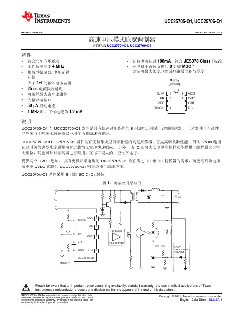
12348765ILIM FB VFF DISCHVDD OUT GND RCUCC25705-Q1,UCC25706-Q1ZHCS082–MAY 2011高速电压模式脉宽调制器查询样品:UCC25705-Q1,UCC25706-Q1特性•符合汽车应用要求•闭锁电流超过100mA ,符合JESD78Class I 标准•工作频率高于4MHz •业界最小占位面积的8引脚MSOP封装可最大限度地缩减电路板面积与厚度•集成型振荡器/电压前馈补偿D 封装•大于4:1的输入电压范围(顶视图)•25ns 电流限制延迟•可编程最大占空比钳位•光耦合器接口•50µA 启动电流•1MHz 时,工作电流为4.2mA说明UCC25705-Q1与UCC25706-Q1器件是具有快速过压保护的8引脚电压模式一次侧控制器。
上述器件可在高性能隔离与非隔离电源转换器中用作内核高速构建块。
UCC25705-Q1/UCC25706-Q1器件具有支持集成型前馈补偿的高速振荡器,可提高转换器性能。
针对25ns 输出延迟时间的典型电流感测可对过载情况实现快速响应。
此外,该IC 还可为实现更高保护功能提供可编程最大占空比钳位,其也可针对振荡器进行禁用,在尽可能大的占空比下运行。
提供两个UVLO 选项。
具有更低启动电压的UCC25705-Q1旨在满足DC 至DC 转换器的需求,而更高启动电压及更宽UVLO 范围的UCC25706-Q1则更适用于离线应用。
UCC2570x-Q1系列采用8引脚SOIC (D)封装。
图1.典型应用原理图Please be aware that an important notice concerning availability,standard warranty,and use in critical applications of Texas Instruments semiconductor products and disclaimers thereto appears at the end of this data sheet.UCC25705-Q1,UCC25706-Q1ZHCS082–ABSOLUTE MAXIMUM RATINGSover operating free-air temperature(unless otherwise noted)(1)(2)VALUE UNIT Supply voltage15VInput voltage(VFF,RC,ILIM)7VInput voltage(FB)15VInput current(DISCH)1mA Output current(OUT)dc±20mA Storage temperature,T stg–65to150°C Junction temperature,T J–55to150°CLead temperature(soldering,10sec)300°C (1)Stresses beyond those listed under“absolute maximum ratings”may cause permanent damage to the device.These are stress ratingsonly,and functional operation of the device at these or any other conditions beyond those indicated under“recommended operating conditions”is not implied.Exposure to absolute-maximum-rated conditions for extended periods may affect device reliability.(2)All voltages are with respect to GND.Currents are positive into,negative out of the specified terminal.Consult /packaging for moreinformation.RECOMMENDED OPERATING CONDITIONSover operating free-air temperature range(unless otherwise noted)VALUE UNITT A Operating ambient temperature–40to105°CORDERING INFORMATION TABLETOP-SIDE T A PACKAGE ORDERABLE PART NUMBERMARKING -–40°C to125°C SOIC-8–D Reel of2500UCC25706QDRQ125706Q-–40°C to125°C SOIC-8–D Reel of2500UCC25705QDRQ1PreviewESD RATINGS TABLEPARAMETER VALUE UNITHuman Body Model(HBM)1000V ESD Charged-Device Model(CDM)1000VMachine Model(MM)200VUCC25705-Q1,UCC25706-Q1 ZHCS082–MAY2011ELECTRICAL CHARACTERISTICSV DD=11V,V IN=30V,R T=47k,R DISCH=400k,R FF=14k,C T=220pF,C VDD=0.1µF,and no load on the outputs,T A= -–40°to125°C,(unless otherwise specified)PARAMETER TEST CONDITIONS MIN TYP MAX UNIT UVLO section(UCCx5705)Start threshold8.08.89.6V Stop threshold7.48.29.0V Hysteresis0.30.6 1.0V UVLO section(UCCx5706)Start threshold11.212.012.8V Stop threshold7.28.08.8V Hysteresis 3.2 4.0 4.5V Supply Current SectionStart-up current V DD=UVLO start–1V,V DD comparator off3090µAI DD active V DD comparator on,oscillator running at1MHz 4.2 5.0mA Line Sense SectionLow line comparator threshold0.95 1.00 1.15V Input bias current(VFF)–100100nA Oscillator SectionFrequency VFF=1.2V to4.8V0.9 1.0 1.1MHzVFF=1.2V,See(1) 1.2VCT peak voltageVFF=4.8V,See(1) 4.8VCT valley voltage See(1)0V Current Limit SectionInput bias current0.2–0.2–1µA Current limit threshold180200220mV Propagation delay,ILIM to OUT50mV overdrive2535ns Pulse Width Modulator SectionFB input impedance V FB=3V305090kΩMinimum duty cycle V FB<2V0%V FB=V DD,F OSC=1MHz707580% Maximum duty cycleV DISCH=0V,F OSC=1MHz93% PWM gain V FF=2.5V,MODE=112%/V Propagation delay,PWM to OUT65130ns Output SectionV OH I OUT=–5mA,V DD–output0.30.6VV OL I OUT=5mA0.150.4V Rise time C LOAD=50pF1025nsFall time C LOAD=50pF1025ns (1)Specified by design.FFFF DISCH 2R VFF VIN 2R R æö´»´ç÷´+èøUCC25705-Q1,UCC25706-Q1ZHCS082–MAY 2011PIN DESCRIPTIONSDISCH:A resistor to VIN sets the oscillator discharge current programming a maximum duty cycle.When grounded,an internal comparator switches the oscillator to a quick discharge mode.A small 100-pF capacitor between DISCH and GND may reduce oscillator jitter without impacting feed-forward performance.I DISCH must be between 25µA and 250µA over the entire V IN range.FB:Input to the PWM comparator.This pin is intended to interface with an optocoupler.Input impedance is 50-k Ωtypical.GND:Ground return pin.I LIM :Provides a pulse-by-pulse current limit by terminating the PWM pulse when the input is above 200mV.This provides a high speed (25ns typical)path to reset the PWM latch,allowing for a pulse-by-pulse current limit.OUT:The output is intended to drive an external FET driver or other high impedance circuits,but is not intended to directly drive a power MOSFET.This improves the controller ’s noise immunity.The output resistance of the PWM controller,typically 60Ωpull-up and 30Ωpull-down,will result in excessive rise and fall times if a power MOSFET is directly driven at the speeds for which the UCC2570x-Q1is optimized.RC:The oscillator can be configured to provide a maximum duty cycle clamp.In this mode the on-time is set by RT and CT,while the off-time is set by R DISCH and CT.Since the voltage ramp on CTis proportional to VIN,feed-forward action is obtained.Since the peak oscillator voltage is also proportional to VIN,constant frequency operation is maintained over the full power supply input range.When theDISCH pin is grounded,the duty cycle clamp is disabled.The RC pin then provides a low impedance path to ground CT during the off time.V DD :Power supply pin.This pin should be bypassed with a 0.1-µF capacitor for proper operation.The undervoltage lockout function of the UCC2570x-Q1allows for a low current startupmode and ensures that all circuits become active in a known state.The UVLO thresholds on the UCC25705-Q1are appropriate for a dc-to-dc converter application.The wider UVLO hysteresis of the UCC25706-Q1(typically 4V)is optimized for a bootstrap startup mode from a high impedance source.V FF :The feed-forward pin provides the controllerwith a voltage proportional to the power supply input voltage.When the oscillator is providing a duty cycle clamp,a current of 2×I DISCH is sourced from the V FF pin.A single resistor R FF between V FF and GND then set V FF to:When the DISCH pin is grounded and the duty cycle clamp is not used,the internal current source is disabled and a resistor divider from VIN is used to set VFF.In either case,when the voltage on V FF is less than 1.0V,both the output and oscillator are disabled.OUTVDDGND ILIMRCVFF FB DISCHUCC25705-Q1,UCC25706-Q1ZHCS082–MAY 2011Figure 2.Block DiagramFUNCTIONAL DESCRIPTIONOscillator and PWMThe oscillator can be programmed to provide a duty cycle clamp or be configured to run at the maximum possible duty cycle.The PWM latch is set during the oscillator discharge and is reset by the PWM comparator when the C T waveform is greater than the feedback voltage.The voltage at the FB pin is attenuated before it is applied to the PWM comparator.The oscillator ramp is shifted by approximately 0.65-V at room temperature at the PWM comparator.The offset has a temperature coefficient of approximately -–2mV/°C.The I LIM comparator adds a pulse by pulse current limit by resetting the PWM latch when V ILIM >200mV.The PWM latch is also reset by a low line condition (V FF <1.0V).All reset conditions are dominant;asserting any output will force a zero duty cycle output.Oscillator With Duty Cycle Clamp (MODE =1)The timing capacitor C T is charged from ground to V FF through R T .The discharge path is through an on-chip current sink that has a value of 30×I DISCH ,where I DISCH is the current through the external resistor R DISCH .Since the charge and discharge currents are both proportional to V IN ,their ratio,and the maximum duty cycle remains constant as V IN varies.FFV INFF FFON T T IN DISCHV 2R T R C where V R ´=a ´´a =»()T T DISCH OFF T DISCHC R ×R T 30R -R ´=a ´´1DISCHT T T DISCH11f R R C 30R -R =´a ´´+´ON DISCH ON OFF T T R Duty Cycle 1T T 30R æö==-ç÷+´èøUCC25705-Q1,UCC25706-Q1ZHCS082–MAY 2011Figure 3.Duty Cycle Clamp (MODE =1)The on-time is approximately:The off-time is:The frequency is:The maximum duty cycle is:FF(min)18V ==1.20V15IN(min)ON(max)T FF(min)TV T R V C ´=´TDISCH FF(min)T T IN(min)OFF(min)30R R V R C V1T ´=æöæö´´ç÷ç÷èøç÷+ç÷ç÷èø()FF(min)DISCHFF IN(min)V R R 2V 1´=´-UCC25705-Q1,UCC25706-Q1ZHCS082–MAY 2011Component Selection for Oscillator With Duty Cycle Clamp (MODE =1)For a power converter with the following specifications:•V IN(min)=18V •V IN(max)=75V •V IN(shutdown)=15V •F OSC =1MHz•MAX =0.78at V IN(min)In this mode,the on-time is approximately:•T ON(max)=780ns •T OFF(min)=220ns•1.Pick C T =220pF.2.Calculate R T .R T =51.1k Ω3.R DISCHR DISCH =383k Ω.I DISCH must be between 25µA and 250µA over the entire VIN range.With the calculated values,I DISCH ranges from 44µA to 193µA,within the allowable range.If I DISCH is toohigh,C T must be decreased.4.R FFThe nearest 1%standard value to the calculated value is 13.7k.V INFF ON T T INV T R C where V =a ´´a =T T 1f R C 75ns=a´´+UCC25705-Q1,UCC25706-Q1ZHCS082–MAY 2011Oscillator Without Duty Cyle Clamp (MODE =0)In this mode,the timing capacitor is discharged through a low impedance directly to ground.The DISCH pin is externally grounded.A comparator connected to DISCH senses the ground connection and disables both the discharge current source and V FF current source.A resistor divider is now required to set V FF .Figure 4.Ocsillator Without Clamp (MODE =0)In this mode,the on-time is approximately:The off-time is:T OFF ≈75ns The frequency is:FF(min)18V 1.2V 15==IN(min)FF(min)OSCT TV 175ns V F R C æö´-ç÷èø=UCC25705-Q1,UCC25706-Q1ZHCS082–MAY 2011Component Selection for Oscillator Without Duty Cycle Clamp (MODE =0)For a power converter with the following specifications:•V IN(min)=18V •V IN(max)=75V •V IN(shutdown)=15V •F OSC =1MHz With these specifications,1.Pick C T =220pF2.Calculate R T .-50-2525575100125Temperature –78910111213°CU V L O --T h r es h o l d s --V-502525575100125Temperature –8.08.18.28.38.48.58.68.78.88.9°CU V L O --Th r e s h o l d s --V--50-2525575100125Temperature –3.84.04.24.34.54.74.83.94.14.44.6°C I D D --m A-50-250255075100125Temperature 0.650.970.991.001.021.041.050.960.981.011.03–°CL o w -L i ne T h r e s h o l d --VUCC25705-Q1,UCC25706-Q1ZHCS082–MAY 2011TYPICAL CHARACTERISTICSUCC25705-Q1UVLO THRESHOLDSUCC25706-Q1UVLO THRESHOLDSvsvsTEMPERATURETEMPERATUREFigure 5.Figure 6.OPERATING CURRENT (AT 1MHz)LOW-LINE THRESHOLDvsvsTEMPERATURETEMPERATUREFigure 7.Figure 8.-50-25255075100125Temperature –0.901.001.100.951.05O s c i l l a t o r F r e q u e n c y --M H z°C-50-250255075100125Temperature 6876827078727480°CP r o g r a m m a b l e M a x i m u m D u t y C y c l e --%-50-2525575100125Temperature –180200220185205190195210215°C C u r r e n t -L i m i t T hr e s h o l d --m V-50-2525575100125Temperature –1525351729192331332127°CC u r r e n t -L i m i t P ro p D e l a y --n sUCC25705-Q1,UCC25706-Q1ZHCS082–MAY 2011TYPICAL CHARACTERISTICSPROGRAMMABLE MAXIMUMOSCILLATOR FREQUENCYDUTY CYCLEvsvsTEMPERATURETEMPERATUREFigure 9.Figure 10.CURRENT-LIMIT THRESHOLDCURRENT-LIMIT PROP DELAYvsvsTEMPERATURETEMPERATUREFigure 11.Figure 12.重要声明德州仪器(TI)及其下属子公司有权在不事先通知的情况下,随时对所提供的产品和服务进行更正、修改、增强、改进或其它更改,并有权随时中止提供任何产品和服务。
QTZ125G(FS6016)使用说明书要点

目录CONTENTS1、概述(Preface) (2)2、起重机技术性能(Technical & Parameters Of The Tower Crane) (5)3、起重机构造简述(Structure Description Of The Tower Crane) (8)4、起重机的安装与拆卸(行走式)(Installation & Disassembly Of The TowerCrane---Mobile) ···············································································35.5、独立固定式起重机的安装与拆卸(Installation & Disassembly Of The FreestandingStationary Crane) (63)6、起重机附着工作状态的安装与拆卸(Installation & Disassembly OfThe Attachment Working State Tower Crane) (64)7、起重机内爬工作状态的安装与拆卸(Installation & Disassembly OfThe ...Working State Tower Crane) . (71)8、起重机的使用(Usage Of The Tower Crane) (88)9、起重机的维护保养(Maintenance Of The Tower Crane) (90)10、附表一Table One 附带部件图、塔式起重机用钢丝绳明细表(Attaching Pictures OfThe Ports and List Of Wire Rope Of The Tower Crane) (94)11、附表二Table Two 各部润滑表(Parts Lubrication) (95)12、附表三Table Three 轴承明细表(List Of The Bearing) (97)13、附表四Table Four 主要部件重量表(Weight Of The Mainly Parts) . (98)14、QTZ系列塔机卸塔注意事项(Precautions for QTZ125(TC5613A)Tower CraneDismantle) (101)15、附图Attached Drawing One 有底架压重固定式基础图(一)~(二)(Stationary towercrane with undercarriage ballast installed according to the procedures shown as fig.(1)~(2) (106)16、附图Attached Drawing Two 直接固定式基础图(一)~(三)installed the stationarytower crane directly according to the procedures shown as fig.(1)~(3) (109)17、附图Attached Drawing Five内爬前独立固定基础图 foundation for innerclimbing forward stationary (111)概述(Preface)QTZ125G(FS6016)塔式起重机是根据JG/T5037《塔式起重机分类》标准设计的新型建筑用塔式起重机。
UCC3570
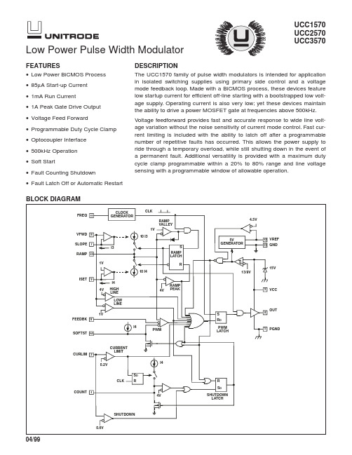
UCC1570UCC2570UCC3570Low Power Pulse Width ModulatorDESCRIPTIONThe UCC1570family of pulse width modulators is intended for application in isolated switching supplies using primary side control and a voltage mode feedback loop.Made with a BiCMOS process,these devices feature low startup current for efficient off-line starting with a bootstrapped low volt-age supply.Operating current is also very low;yet these devices maintain the ability to drive a power MOSFET gate at frequencies above 500kHz.Voltage feedforward provides fast and accurate response to wide line volt-age variation without the noise sensitivity of current mode control.Fast cur-rent limiting is included with the ability to latch off after a programmable number of repetitive faults has occurred.This allows the power supply to ride through a temporary overload,while still shutting down in the event of a permanent fault.Additional versatility is provided with a maximum duty cycle clamp programmable within a 20%to 80%range and line voltage sensing with a programmable window of allowable operation.10I310I4I3I4I4I41074119VFWDFREQ SLOPE RAMP ISET CLOCK GENERATOR1V4VHIGH LINE LOW LINE1VFEEDBK SOFTST CURLIM CURRENT LIMITCLKRAMP VALLEY RAMP PEAKRAMP LATCH4V1VS R5VGENERATOR4.5VVREF 15VGND13/9VVCCOUTPGNDPWM PWMLATCHR DS R0.2VCLKCOUNT 814214VSHUTDOWN LATCHSHUTDOWN0.6VR S D6121335S DBLOCK DIAGRAMFEATURES•Low Power BiCMOS Process •85µA Start-up Current •1mA Run Current•1A Peak Gate Drive Output •Voltage Feed Forward•Programmable Duty Cycle Clamp •Optocoupler Interface •500kHz Operation •Soft Start•Fault Counting Shutdown•Fault Latch Off or Automatic RestartSupply Voltage(Limit Supply Current to 20mA). . . . . . .Self Limiting at 15V Supply Current . . . . . . . . . . . . . . . . . . . . . . . . . . . . . . . . . . .+20mA Analog Inputs (CURLIM,VFWD,FEEBK). . . . . . . . . . . . . .6V Programming Current I SLOPE ,I ISET . . . . . . . . . . . . . . . . .–1mA Output Current I OUTDC . . . . . . . . . . . . . . . . . . . . . . . . . . . . . . . . . . . . .±180mA Pulse (0.5ms). . . . . . . . . . . . . . . . . . . . . . . . . . . . . . .±1.2ANote :All voltages are with respect to GND.Currents are posi-tive into the specified terminal.Consult Packaging Section of Databook for thermal limitations and considerations of pack-age.ABSOLUTE MAXIMUM RATINGSCONNECTION DIAGRAMSELECTRICAL CHARACTERISTICS:Unless otherwise stated, these specifications apply for T A = 0 to 70°C for theUCC3570, T A = –40 to 85°C for the UCC2570, T A =–55 to 125°C for the UCC1570,R ISET =100k,R SLOPE =121k,C FREQ =180pF,C RAMP =150pF,VCC=11V and T A =T J .PARAMETERTEST CONDITIONSMin Typ Max Units Reference VREFVCC =10 to 13V,I VREF = 0 to 2mA 4.95 5.1V Line Regulation VCC = 10 to 13V 210mV Load Regulation I VREF = 0 to 2mA 210mV Short Circuit Current VREF = 01050mA VCCVth (On)1213V Vth (Off)8910V Hysteresis 345V VCCI VCC = 10mA13.51516V I VCC Start VCC = 11V,VCC Comparator Off 85150µA I VCC RunVCC Comparator On11.5mATemperature Range Package UCC1570J –55°C to +125°C Ceramic Dip UCC2570D –40°C to +85°CSOICUCC2750N Plastic Dip UCC3570D 0°C to +70°CSOICUCC3570N Plastic Dip UCC3570QPLCCORDERING INFORMATIONELECTRICAL CHARACTERISTICS:Unless otherwise stated, these specifications apply for T A= 0 to 70°C for theUCC3570, T A= –40 to 85°C for the UCC2570, T A=–55 to 125°C for the UCC1570,R ISET=100k,R SLOPE=121k,C FREQ=180pF,C RAMP=150pF,VCC=11V and T A=T J.PARAMETER TEST CONDITIONS Min Typ Max Units Line SenseVth High Line Comparator 3.94 4.1V Vth Low Line Comparator0.961 1.04V lib (VFWD)0±100nA OscillatorFrequency90100110kHz Ramp GeneratorI RAMP/I SLOPE91011A/A–I RAMP/I ISET91011A/A Peak Ramp Voltage 3.84 4.2V Valley Ramp Voltage0.951 1.05V ISET Voltage Level0.951 1.05V Soft StartSaturation VCC= 11V,VCC Comparator Off25100mVI SOFTST/I ISET0.81 1.2A/A Pulse Width Modulatorlib(FEEDBK)0±100n A FEEDBK Zero Duty Cycle0.91 1.1VMaximum Duty Cycle, (Note 1) 3.84 4.2V Current Limitlib(CURLIM)0±100nA Vth Current Limit180200220mV Vth Shutdown500600700mV Fault CounterVth 3.84 4.2V Vsat0100mVI COUNT/I ISET0.81 1.2A/A Output DriverVsat High I OUT= –100mA0.41V Vsat Low I OUT= 100mA0.41V Rise/Fall Time C OUT= 1nF, (Note 1)20100nsNote 1:This parameter guaranteed by design but not 100% tested in production.VCC:Chip supply voltage pin.Bypass to PGND with a low ESL/ESR0.1µF capacitor plus a capacitor for gate charge storage.Lead lengths must be minimum.PGND:Ground pin for the output driver.Keep connec-tions less than2cm.Carefully maintain low impedance path for high current return.OUT:Gate drive output pin.Connect to the gate of a power MOSFET with a resistor greater than2Ω.Keep connection lengths under 2cm.VFWD:Voltage Feed Forward and Line Sense pin.Con-nect to input DC line using a resistive divider.SLOPE:Program the charging current for RAMP with a resistor from this pin to GND.This pin will follow VFWD.FEEDBK:Input to the pulse width modulator comparator. Drive this pin with an optocoupler to GND and a resistor to VREF.Modulation input range is from 1V to 4V.ISET:A resistor from this pin to GND programs RAMP discharge current,FREQ current,SOFTST current,and COUNT current.PIN DESCRIPTIONSRAMP:Ramp Pin.Connect a capacitor to GND.Rising slope is programmed by current in SLOPE.This slope is compared to FEEDBK for pulse width modulation.The falling slope is programmed by the current in ISET and used to limit maximum duty cycle.FREQ:Oscillator pin.Program the frequency with a ca-pacitor to GND.VREF:Precision5V reference,and bypass point for inter-nal circuitry.Bypass this pin with a1µF minimum capaci-tor to GND.GND:Analog ground.Connect to a low impedance ground plane containing all analog low current returns. SOFTST:Soft start pin.Program with a capacitor to GND.COUNT:Program the time that fault events will be toler-ated before shutdown occurs with a capacitor and resis-tor to GND.CURLIM:Current Limit Sense pin.Terminates OUT gate drive pulse for inputs over0.2V.Enables fault counting function(COUNT).For inputs over0.6V,the shutdown latch is activated.PIN DESCRIPTIONS(cont.)(Note:Refer to Typical Application for external compo-nent names.)All the equations given below should be considered as first order approximations with final values determined empirically for a specific application.Power SequencingVCC normally connects through a high impedance(R5) to the rectified line,with an additional path(R6)to a low voltage,bootstrap on the winding power transformer. VFWD normally connects to a divider(R1and R2)from the rectified line.For circuit activation,all of the following considerations are required:1.VFWD between 1V and 4V2.VCC has been under9V(to reset the shutdownlatch)3.VCC over 13VAt this time,the circuit will activate.I VCC will increase from its start up value of85µA to its run value of1mA. The capacitor on SOFTST is charged with a current de-termined by:–IVR SOFTST=14.When SOFTST rises above1V,output pulses will begin and I VCC will further rise to a level dictated by gate charge requirements asI VCC≈1mA+QTfs.With output pulses,the low voltage bootstrap winding should now power the controller.If VCC falls below9V,the controller will turn off and the start sequence will reset and retry.VCC ClampAn internal shunt regulator clamps VCC so that it will not exceed 15V.Output InhibitDuring normal operation,OUT is driven high at the start of a clock period and back low when RAMP either crosses FEEDBK or equals4V.If,however,any of the fol-lowing occur,OUT is immediately driven low for the re-mainder of the clock period:1.VFWD is outside the range of 1V to 4V2.CURLIM is greater than 0.2V3.FEEDBK or SOFTST is less than 1VNormal output pulses will not resume until the beginning of the next clock period in which none of the above con-ditions exist.Current LimitingCURLIM is monitored by two internal comparators.The current limit comparator threshold is0.2V.If the current limit comparator is triggered,OUT is immediately driven low and held low for the remainder of the clock cycle, providing pulse-by-pulse overcurrent control for exces-sive loads.This comparator also causes C F to be charged for the remainder of the clock cycle.The charg-ing current is–IVRCOUNT=14.If repetitive cycles are terminated by the current limit comparator causing COUNT to rise above4V,the shut-down latch is set.The COUNT integration delay feature will be bypassed by the shutdown comparator which has a0.6V threshold.The shutdown comparator immediately sets the shutdown latch.R F in parallel with C F resets the COUNT integrator following transient faults.R F must be greater than()()441•−RD MAX.APPLICATION INFORMATIONLatched ShutdownIf CURLIM rises above0.6V,or COUNT rises to4V,the shutdown latch will be set.This will force OUT low,dis-charge SOFTST and COUNT,and reduce I VCC to ap-proximately1mA.When,and if,VCC falls below9V,the shutdown latch will reset and I VCC will fall to85µA,allow-ing the circuit to restart.If VCC remains above9V,an al-ternate restart will occur if VFWD is momentarily reduced below1V.External shutdown commands from any source may be added into either the COUNT or CURLIM pins. Deadtime ControlThe voltage waveform on RAMP has independently con-trolled rising and falling edges.At the start of the clock period,RAMP is at1V and rises to4V.It then discharges back to1V and awaits the next clock period.OUT can only be high during the rising part of the waveform,while it is positively blanked off during the falling portion.Set-ting the–dV/dt slope by R4from ISET to GND estab-lishes a minimum deadtime as:td R C R=••034.Choose R4between20k and200k and C R greater than 50pF.In order to have a pulse at OUT in the next clock period,RAMP must fall to1V prior to the end of the cur-rent period.If it does not,OUT will remain low for the en-tire next clock period.Voltage FeedforwardThe+dV/dt on RAMP is made proportional to line volt-age.The slope is:()dVdtVFWDR C R=••103where VFWD is line voltage scaled by R1and R2.There-fore,a changing line voltage will accomplish an immedi-ate proportionate pulse width change without any action from the feedback amplifier.This will result in constant volt-second drive to the power transformer providing both international voltage operation,and excellent dynamic line regulation.VFWD is intended to operate over a4:1 range(1V to4V)with undervoltage and overvoltage sen-sors designed to drive OUT low if this range is exceeded. Choose R3 between 20k and 200k.APPLICATION INFORMATION (cont.)Frequency SetA capacitor from FREQ to GND will determine a constant clock frequency.Frequency is:()F R C T =•184.If required,frequency can be trimmed down from the above equation by the addition of R T from FREQ to GND.The reduction in frequency is a function of the ratio of R T/R4.R T should be greater than 2.4•R4for reliable op-eration.External synchronization can be accomplished by cou-pling a narrow pulse to a resistor inserted in series with the ground side of C T.The value should be less than R4/200and the synchronizing pulse width should be less than 5% of the oscillator period.External synchronization can also be accomplished by driving FREQ with an CMOS inverter.The inverter mustbe able to sink (4•I4)with at a voltage less than the 3.5V upper threshold of the oscillator.It must also be able to source 36•I4at a voltage greater than the 1.5V lower threshold of the oscillator.As long as FREQ is held high, the output is guaranteed to be low.Gate Drive OutputThe UCC1570is capable of 1A peak output current.By-pass VCC with at least 0.1µF directly to e a capacitor with low equivalent series resistance and in-ductance.The connection from OUT to the MOSFET gate should have a 2Ωor greater damping resistor and the length should be minimized.A low impedance con-nection must be established between the MOSFET source (or the ground side of the current sense resistor),the VCC bypass capacitor and PGND.PGND should then be connected by a single path (shown as RGND in the application) to GND.APPLICATION INFORMATION (cont.)APPLICATION INFORMATION (cont.)UCC1570UCC2570UCC3570UNITRODE CORPORA TION7 CONTINENTAL BLVD.•MERRIMACK, NH 03054TEL.(603) 424-2410FAX (603) 424-3460APPLICATION INFORMATION (cont.)IMPORTANT NOTICETexas Instruments and its subsidiaries (TI) reserve the right to make changes to their products or to discontinue any product or service without notice, and advise customers to obtain the latest version of relevant information to verify, before placing orders, that information being relied on is current and complete. All products are sold subject to the terms and conditions of sale supplied at the time of order acknowledgement, including those pertaining to warranty, patent infringement, and limitation of liability.TI warrants performance of its semiconductor products to the specifications applicable at the time of sale in accordance with TI’s standard warranty. Testing and other quality control techniques are utilized to the extent TI deems necessary to support this warranty. Specific testing of all parameters of each device is not necessarily performed, except those mandated by government requirements.CERTAIN APPLICATIONS USING SEMICONDUCTOR PRODUCTS MAY INVOLVE POTENTIAL RISKS OF DEATH, PERSONAL INJURY, OR SEVERE PROPERTY OR ENVIRONMENTAL DAMAGE (“CRITICAL APPLICATIONS”). TI SEMICONDUCTOR PRODUCTS ARE NOT DESIGNED, AUTHORIZED, OR WARRANTED TO BE SUITABLE FOR USE IN LIFE-SUPPORT DEVICES OR SYSTEMS OR OTHER CRITICAL APPLICATIONS. INCLUSION OF TI PRODUCTS IN SUCH APPLICATIONS IS UNDERSTOOD TO BE FULLY AT THE CUSTOMER’S RISK.In order to minimize risks associated with the customer’s applications, adequate design and operating safeguards must be provided by the customer to minimize inherent or procedural hazards.TI assumes no liability for applications assistance or customer product design. TI does not warrant or represent that any license, either express or implied, is granted under any patent right, copyright, mask work right, or other intellectual property right of TI covering or relating to any combination, machine, or process in which such semiconductor products or services might be or are used. TI’s publication of information regarding any third party’s products or services does not constitute TI’s approval, warranty or endorsement thereof.Copyright © 1999, Texas Instruments IncorporatedCopyright © Each Manufacturing Company.All Datasheets cannot be modified without permission.This datasheet has been download from :100% Free DataSheet Search Site.Free Download.No Register.Fast Search System.。
FURUNO FS2570MFHF电台中文说明书

第一章日本古野FURUNO FS-2570 MF/HF组合电台日本FURUNO古野公司生产的GMDSS中频/高频(MF/HF)组合电台主要有三种型号,150W的FS-1570组合电台,250W的FS-2570组合电台和400W的FS-5000组合电台,下面以FURUNO FS-2570 MF/HF组合电台为例介绍FURUNO组合电台的功能。
第一节面板控制键和指示灯介绍POWER(电源开关):开启/断开电源。
DISTRESS(遇险按钮):按住此按钮三秒以上发射遇险报警。
开始按时灯闪,大于三秒后灯亮。
收到遇险应答电报后灯灭。
如果按住此按钮少于三秒不会发射遇险报警。
CALL:发射除遇险外的呼叫。
ENTER KNOB(输入按钮和选择旋钮):无线电话时,旋转改变TX/RX信道、灵敏度、音量等,按一下是输入功能;DSC时,旋转选择菜单项目,按一下是输入功能。
CANCEL:取消错误的数据,恢复先前的菜单,消除音响报警,取消发射,删除错误信息。
1/RT/2182:按一下从平时值守的DSC屏幕转换到SSB无线电话设置屏幕,连续按两秒以上直接转换到2182.0KHZ的遇险无线电话通信屏幕。
2/DSC:编辑DSC发射电文。
3/TEST:进行日常试验。
4/IntCom:接通/关闭与其他控制单元FS-2570C的内部通信。
5/ACK/SQ:在DSC时,改变是自动发收妥通知还是手动发收妥通知,关键点,一般不要使用自动发收妥通知,因为这样会使操作员错过许多呼叫;在SSB时,打开/关闭静噪功能。
6/SCAN:在DSC的值守屏幕,启动/停止在DSC频率上的扫描值守功能。
7/喇叭:接通/断开喇叭。
8/PRINT:打印通信日志文件、当前显示屏(除DSC准备状态屏幕和无线电话屏幕)和测试结果。
9/灯光:调节面板亮度和液晶显示器(LCD)的对比度。
FILE/CURSOR:在DSC准备屏幕打开已存储的发送文件夹,选择要发送的电文;移动光标。
SHL-2570B贴标机操作规程
4贴标
4.1试贴标
4.1.1如下图,在自动运行画面按下“贴标”和“打印”按钮,操作面板上这两个按键由红色变为绿色。
4.1.2先不开转盘,先准备10支待贴标产品放在传送带上,人机界面上按下“启动”按钮,先试贴10支产品,查看贴签效果。
3.2.2输入对应登录密码,进入贴标机“自动运行画面”,如下图:
3.2.3点击“用户切换”可切换至其他操作用户,设备共有三个操作权限,详情如下:
操作员:仅可操作设备贴标、打印和转盘运行。
技术员:除操作员权限外,还可进行参数设定。
管理员:除技术员权限外,还可修改密码。
3.3参数设置
3.3.1点击“参数”可进入“参数设定”画面,如下图。在此界面修改打印时间,增加打印时间(每次增加不超过2毫秒),标签打印颜色会加深;减少打印时间(每次减少不超过2毫秒),标签打印颜色会变浅;其他不用设置。
2.1.2将标签尾端固定于标签底纸卷筒,锁上收纸固定块。
2.1.3注意:压标海绵块不能压得过紧,否则可能导致标签断裂。也不能过松,否则会导致印字时前时后。
2.2装置色带
先确认色带的正反方向,按照设备上的色带缠绕图位置放置色带,并将底部导带环高度移至适当位置,确实将色带拉顺,并锁上色带固定螺栓。
2.3装置印字码
3.3.2参数设定点击“选择记忆组”进入设备的“记忆组画面”,此界面可选择“系统检测”、“产量设定”、“手动操作”、“异常记录”等选项,如下图。即可对该记忆组的相关参数进行修改。
3.3.3确认标签已装好且连续不间断,点击“系统检测”开始执行,设备自动出3~5张标签执行检测,检测完成后须手动将出标签取出。如超过5张仍未检测完成,须设备关闭电源等待20秒再开机启动。
FS-0.5A-Ⅰ防坠器使用说明书
FS-0.5A-Ⅰ型防坠器使用说明书山东省济宁煤矿机械厂目录一、简介1、用途2、主要技术特征3、各部分构造及其作用(1) 抓捕器(2) 缓冲器(3) 制动绳、缓冲器及连接器(4) 拉紧装置二、在矿井安装防坠器1、准备工作2、缓冲器的安装3、制动绳的悬挂及浇注轴承合金4、悬挂罐笼及穿入制动绳5、制动绳在井底的固定与拉紧、缓冲绳的最后固定三、试验1、试验前的准备工作2、试验程序(1) 检查性试验(2) 静负荷试验(3) 脱钩试验(4) 试验后的恢复工作及试验报告四、维护检修1、日检(1) 抓捕器的检查(2) 制动绳的检查(3) 拉紧装置的检查(4) 缓冲装置的检查2、月修3、大修简介1、用途Fs一0.5A一1型防坠器是竖井罐笼上的一种安全装置。
在提升过程中,一旦提升钢丝绳断绳或连接装置断裂时,它能自动抓住制动绳,使罐笼平稳停住,不致坠入井底,从而保证人员的安全和提升设备不致损坏。
此防坠器与西安煤矿设计院所设计所的0.5吨单层单车钢丝绳罐道普通罐笼(TS0622(1)一301一00]配合使用。
2、主要技术特征3、各部分的构造及其作用该防坠器在结构上主要有安装在罐笼上部的抓捕器、井架上的缓冲器、井底水窝内的拉紧装置以及制动绳、缓冲绳和连接此二绳的连接器组成。
见图一。
图一防坠落器布置图(1)抓捕器:抓捕器的主要作用是当提升钢丝绳断绳时,能自动动作,并安全可靠的抓住制动绳,使断绳后的罐笼悬挂在制动绳上。
如图二所示:图二抓捕器抓捕器主要有楔型抓捕机构、传动机构和开动机构组成,其中传动机构有主拉杆6、横担8、连板9和叉杆1组成;开动机构由弹簧7等组成。
楔型抓捕机构(楔盒)如图二(a)所示;它由内壁板、外壁板、楔子,楔背和圆柱滚子所组成。
在罐笼正常运行时,由于提升钢丝绳的拉力作用,驱动弹簧处于压缩状态,楔型抓捕机构的楔子与制动绳之间有8mm的间隙,制动绳可以顺利通过,保证罐笼正常运行。
一旦发生断绳事故时,驱动弹簧伸张,带动叉杆围绕转轴旋转,并向上推动楔子,使楔子紧贴制动绳,在楔子与制动绳之间产生摩擦力,这个摩擦力使楔子继续向上移动,直到最后完全抓住制动绳,迫使罐笼平稳停住。
电力测功机使用说明书
普联CAC交流电力测功机使用说明书目录一、概述...................................................错误!未定义书签。
二、主要技术参数 ........................................错误!未定义书签。
三、测功机安装...........................................错误!未定义书签。
四、电缆...................................................错误!未定义书签。
五、布线...................................................错误!未定义书签。
六、产品使用的工作条件和环境条件...................错误!未定义书签。
七.联轴器尺寸...........................................错误!未定义书签。
八、应用实例..............................................错误!未定义书签。
1、发动机性能试验.........................................错误!未定义书签。
2、变速箱性能、寿命试验...................................错误!未定义书签。
一、概述CAC系列交流电力测功机是动力机械功率试验的负载。
标准的CAC系列交流电力测功机由一台交流电机,一套转矩、转速测量传感器、底座及与动力机械连接的法兰,一套可四象限运行的ACS交流变频调速与配电系统,一台交流电力测功机测控仪组成。
其工作原理是将交流电机发出的交流电经ACS变频器逆变为直流电然后再逆变为交流电上网。
ACS交流变频调速系统调节电机的上网电流来控制原动机的转速和扭矩。
如与我公司生产的FC2000系列测控系统配套使用时除了可以对各种旋转动力机械的转速、扭矩进行精确测量和控制,还可以对温度、压力、流量、电流、电压------等参数进行测量、控制。
Furuno RC18xx系列GMDSS控制台日常检测手册 说明书

FURUNO USA A3 GMDSS CONSOLE DAILY TEST MANUALMODEL: RC18xx SeriesFURUNO USATABLE OF CONTENTSThis manual contains the daily self-tests for all equipment in the Furuno USA GMDSS console. These tests are to assist in determining the daily operational status of console and its associated equipment.A daily test log is included and is to be used as a supplement for the current ship’s radio log.1. DMC-5 (1)2. DP-6 (2)3. DSC-60 (3)4. Felcom 15 (4)5. FM-8800 .................................................................... .56. FS-1570/FS-2570 (6)7. FS-5000 (7)8. IB-583 (8)9. Daily Test Log (9)1.1 DMC-51.1.1 Testing1) Press the [TEST] key to begin. 2) In 5 seconds the test will begin.3) For more detail, press the [ENT].All tests should be OK. Record all errors and contact your Furuno agent. 4) Press the [CANCEL]key to end.2.1 DP-62.1.1 Testing1) Press the [F6] key to begin.2) Use the arrow keys to select Change.3) Use the down arrow key to select Self Test.4) Press the [Enter] key to start the test.5) If NG appears, record the error and contact your Furuno agent.6) Press the [Esc] key to end.3.1 DSC-603.1.1 Testing1) Press the [3/TEST] key to begin.2) The test will run automatically and print the results.3) All tests should be OK. If any errors are shown, record them andcontact your Furuno agent.4) Press the [CANCEL] key to end.4.1 Felcom 154.1.1 Testing1) Log out the unit.2) Press the [F7], [7], and then [3] to enter the self-test.3) Select Yes, and press the [Enter] key.4) All tests should be OK. If any errors are shown, record them andcontact your Furuno agent.5) Press the [Esc] key to end.5.1 FM-88005.1.1 Testing1) Select a channel not in use. Press and hold down the PTT switchfor more than one second before starting the self test.2) Press the [SHIFT] key, then the [TEST] key. The test will now begin.3) If you did not press the PTT switch, NO CHECK will appear instead of OK.4) The Distress button and ALARM light will turn on and the alarm will sound.Press the [CANCEL] key once, to silence the alarm.5) Record any errors and contact your Furuno agent.6) Press the [CANCEL] key a second time to end the test.6.1 FS-1570/FS-25706.1.1 Daily Test1) At the DSC screen press the [3/TEST] key.2) Press the [3] key. The test will now begin.3) The audio alarm will sound and the test will print.4) Press the [CANCEL] to silence the alarm.5) Record any errors and contact your Furuno agent.6) Press the [CANCEL] key to end the test.7.1 FS-50007.1.1 Testing1) Press the [CANCEL] key.2) Press the [RCL] key.3) Enter 9900, then press the [ENT] key.4) When the test is complete the display should show OK.5) If an error code appears, record it and contact your Furuno agent.Daily Test Manual8.1 IB-5838.1.1 Testing1) Press the [F6] key to begin.2) Use the arrow keys to select Change.3) Use the down arrow key to select Self Test.4) Press the [Enter] key to start the test.5) If NG appears, record the error and contact your Furuno agent.6) Press the [Esc] key to end.8DAILY TEST LOGMonth YearDaySunday Monday Tuesday Wednesday Thursday Friday SaturdayOK OK OK OK OK OK OK DMC-5DP-6DSC-60Felcom 12FM-8800 #1FM-8800 #2FS-1570FS-2570FS-5000IB-583Initials:Notes:9。
夏普AQUOS S2说明书
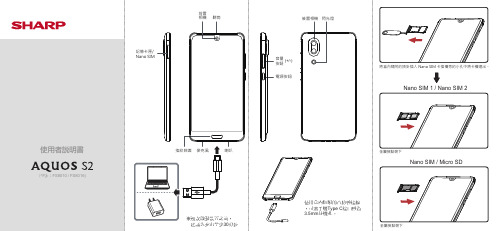
記憶卡匣/ Nano SIM前置電源按鈕音量 (+/-)按鈕後置相機閃光燈※初次啟動裝置之前,建議先充電至少30分鐘使用盒內隨附的音頻轉接線,可將手機Type C接口轉為3.5mm耳機孔。
使用電池的安全注意事項道路及環境安全飛航安全• 本手機電池不可拆,請勿自行拆裝,若不當更換會有爆炸之危險。
• 請依照當地法規回收或處理廢棄電池。
警語智慧財產權資訊免責條款保固聲明保固範圍SHARP 提供「產品保固聲明」,針對客戶向SHARP 或授權的代理經銷商,所購買合法授權標示SHARP 產品,提供產品保固服務。
SHARP 並無提供全球維修保固服務。
產品於正常環境使用之下,因原物料及加工過程中之瑕疵而導致故障,功能無法正常使用,提供一年的保固服務,產品的保固期限自該「機器」的購買日起算,消費者須出示原始購買日之購買證明始能享有保固服務。
保固期限內,發生不在「免責條款」內的自然損壞故障,則SHARP 將提供貴客戶免費的「維修服務」,任何經過維修後的機器,依舊是以最初購買機器時的保固期限為準,並不做延長。
針對超過保固期或是人為損害的維修品,對其同一問題點,提供三個月維修保固,「維修服務」指的是對故障機器內的零件,提供一對一的零件置換動作,以恢復機器正常運作;任何被更換下來的故障零件,其資產屬於SHARP 所有;消耗性和/或消耗性物品或零件例如:除可拆卸式電池為六(6)個月保固與不可拆卸式電池為十二(12)個月保固外,其他配件限於線材、耳機、電源變壓器(若有提供者),則為六(6)個月保固。
當機器外殼上的機器序號被撕毀或被不當更改時,則該機器將無法享有保固權益。
擅自除去或更動機器序號內零件之識別標籤,則該零件亦無法享有保固權益。
當機器出現下面幾種情形時,該機器將無法享有SHARP 原廠的保固權益:(1) 經過SHARP 判斷,機器因為被不當的使用、操作疏忽、不當安裝 維護、經由非SHARP 授權之人員拆卸、維修、擅自更改產品結構 使用非SHARP 原廠所提供的零件或裝置,所導致之故障損壞。
- 1、下载文档前请自行甄别文档内容的完整性,平台不提供额外的编辑、内容补充、找答案等附加服务。
- 2、"仅部分预览"的文档,不可在线预览部分如存在完整性等问题,可反馈申请退款(可完整预览的文档不适用该条件!)。
- 3、如文档侵犯您的权益,请联系客服反馈,我们会尽快为您处理(人工客服工作时间:9:00-18:30)。
FS1570 FS2570操作说明书命安全情况下,才可以发射遇险警报。
1.打开DISTRESS按钮盖,按下该键三秒钟打开下列画面,释放[DISTRESS]按钮2.等到遇险呼叫被发送之后,就会显示下面画面:3.发出声音报警,按[CANCEL]键可消音4.通过无线电话联系岸台的操作步骤如下(在双向控制系统,遇险警报已经发射之后,可通过任意控制单元进行通信.在完成遇险通信后,为恢复#1控制单元优先权,先关闭机器,才重新启动)a)说MAYDAY(遇险)三次b)说”这是……”船的名字和呼号三次c)说遇险的种类和需要的援助d)描述本船的详细情况(类型,船员数量等)和其他可以帮助营救的信息。
1OPERATIONAL OVERVIEW操作综述1.2Turning the Power On/Off打开/关闭电源按控制单元右边的[POWER]按键打开系统.再按一次关闭系统.在双向控制系统, 连接到发射单元CONTROLLER 1端口的控制单元有优先权,它控制No.1和No.2控制单元的电源.No.2控制单元电源开关只控制No.2注意:船电打开5分钟后才可以打开设备电源1.3Panel Dimmer, LCD Contrast面板亮度,LCD对比度1.按9键打开亮度/对比度窗口2.转动[ENTER]旋钮选择DIMMER或CONTRAST,按[ENTER]确认3.转动[ENTER]旋钮调节4.按[ENTER]键选择”EXIT[ENT]”关闭菜单1.4Indications1.4.1DSC standly screen DSC待发射画面按[6/SCAN]键显示DSC待发射画面1.4.2Radiotelephone screen无线电话画面按[1/RT/2182]键显示无线电话画面.这里可设置无线电话的项目1.5Loudspeaker扩音器1.按7键打开或关闭喇叭2.按下列步骤调节喇叭音量:a)按1键显示无线电话画面b)转动[ENTER]键选择VOLc)转动[ENTER]键选择音量大小1.6Scanning Routine DSC Frequencies扫描常规DSC频率利用DSC模式扫描频率,可按7.4节设置频率.扫描时无线电话和电报不起作用.1.按6键显示DSC待发射画面2.按6键启动/停止扫描1.7Automatic Acknowledge on/off打开/关闭自动应答当收到个人的,位置或查询呼叫,DSC自动应答功能/听筒自动发射应答信号给对方.(对于位置和查询呼叫,自动应答菜单里的项目自动打开以便自动应答).自动应答功能可在待发射画面时按5键打开或关闭1.8Manual Entry of Position and Time手动输入位置和时间如果没有EPFS(电子定位标系统)连接到此设备或EPFS出错时,手动输入位置和时间:1.在DSC待发射画面,按[#SETUP]键打开设置菜单2.转动[ENTER]键选择POSITION3.按[ENTER]打开INPUT TYPE菜单4.转动[ENTER]键选择MANUAL5.按[ENTER]键打开纬度窗口,利用数字键输入纬度.6.按[ENTER]键打开经度窗口,利用数字键输入经度.7.按[ENTER]键打开时间窗口8.输入UTC时间9.按[CANCEL]返回DSC待发射画面1.92 SSB RADIOTELEPHONE2.1Transmitting发射选择发射类别和频率,就可以按PTT发射信号,输出功率在屏幕上显示.2.1.1Choosing class of emission选择发射类别1 在无线电话画面,按下列选择发射类别:转动[ENTER]选择MODE(模式)转动[ENTER]选择相应模式:SSB无线电话,TLX电报窄带,AM调幅(AM模式不能发射)2AGC是根据模式自动选择.AGC FAST:无线电话,AGC OFF:电报窄带,AGC SLOW:调幅.可按下列步骤改变:a)转动[ENTER]选择AGCb)转动[ENTER]按钮选择OFF,SLOW或FAST2.1.2Choosing channel, frquency选择频道和频率Choosing channel选择频道1 转动[ENTER]选择CH,然后按[ENTER]键3用数字键输入频道,或转动[ENTER]旋钮输入频道Choosing frequency选择频率1 转动[ENTER]旋钮选择TX或RX2 用数字键输入频率2.1.3Tuning调谐当天线阻抗和发射阻抗相匹配时,才能产生最大发射功率.可通过天线调谐器调谐,使输出功率最大1 按住PTT或按[LOG/TUNE]键更换新的频率后,调谐过程大约2-5秒,调谐成功时,屏幕显示TUNE:OK2.1.4Using the handset利用话筒按住花筒的PTT即可讲话2.1.5Monitoring transceiver output power监视发射机输出功率在发射过程中,屏幕下方的IA条根据天调的反馈信号而变动.2.1.6Reducing transmitter power选择发射功率1 转动[ENTER]键选择LOW, MID或HIGH22.1.7Displaying IA,IC,VC,RF2.2Receiving接收2.2.1RF gain(sensitivity) adjustment射频增益调整正常使用时,灵敏度设为最大.如果在接收频道上的声音不清楚或其他信号干扰,调整灵敏度使声音变清楚.1 转动[ENTER]选择SEN2 转动[ENTER]调整灵敏度2.2.2S-meter信号强度指示器S-meter显示接收机的信号强度.注意:当AGC关闭时,S-meter不起作用.2.2.3Monitoring traffic on intended transmit frequency选择半双工信道,2.2.4Receiving AM broadcasting stations接收调幅广播1 按1键打开无线电话画面2 转动[ENTER]选择MODE3 转动[ENTER]选择AM4 转动[ENTER]选择RX5 输入接收频率2.2.5Squelch control, squelch frequency2.2.6Noise blanker静噪静噪功能是消除噪声,按下列步骤操作:1 在无线电话画面,按[#SETUP]键2 转动[ENTER]选择NB3 按[ENTER]键4 转动[ENTER]选择ON或OFF,按[ENTER]键5 按[CANCEL]键返回无线电话画面2.3Intercom内部通信FS-2570C的两个控制单元之间建立内部通信1 按1键显示无线电话画面2 拿起话筒3 按4键显示INTERCOM.被叫的话筒响.2.4Telex Communications电报窄带通信详见第8节2.5When Automatic Fails2.6User Channels2.72.8Speaker Setting in Off Hook拿起听筒时,可以打开或关闭扬声器。
默认设置是关闭,按下列步骤设置:1.在无线电话画面,按[#SETUP]打开SETUP菜单2.转动[ENTER]键选择OFFHOOKED,然后再按该键3.转动[ENTER]键选择ON或OFF4.按[CANCEL]关闭菜单3 DSC OVERVIEW3.1What is DSC?DSC是字母缩写,意思是数字选呼系统.它是一种在中高频的,船用发射遇险警报和一般呼叫、岸用发射应答信号的数字遇险和呼叫系统。
DSC遇险和安全警报在中高频波段,频率是2187.5,4207.5,6312.0,8414.5, 12577.0, 16804.5DSC站台通过无线电话发射和接收DSC普通和安全呼叫3.2DSC CallDSC呼叫一般分为两种类型:遇险和安全呼叫,常规呼叫.下面是这两种DSC呼Contents of a DSC call●Station ID本船ID和发送站台ID。
岸台ID以00开头,群ID以0开头。
●PriorityDistress:逼近危险物和立即要求支援Safety:站台即将发送一个包含重要航行信息或气象告警的呼叫Urgency:站台要发送紧急呼叫,该呼叫关系到船或人的安全,Business:各船之间的航行,目的等需要通信Routine:全呼●Communication type通信方式Telephone:单边带J3ENBDP-ARQ:NBDP终端的ARQNBDP-FEC:NBDP终端的FEC●Communication frequency发送信号岸台有指定分配的接收频率可供使用●Position位置可以自动或手动发送●DSC frequency如果呼叫类型是SAFETY,URGENCY或DISTRESS,选择DSC遇险频率●End codeDSC呼叫后面是ACK RQ(请求回答),ACK BQ(确认回答)或EOS(结束)3.2.1 Distress alert call and reply遇险警报呼叫和转发在遇险情况下,本船发送的呼叫的类型,利用[DISTRESS]键操作:1.[DISTRESS]键的LED灯开始是闪烁的,当按下该键超过3s后灯一直亮着?(如果少于3s,遇险警报没有发送,一旦警报发送就不能取消)2.无线电话自动设置DSC遇险频率和自动发送呼叫3.遇险警报发送之后(大约40s完成),发射机等待来自岸台的遇险应答(DIST ACK)这个一般在3分钟之内.(如果超过4-5分钟,遇险呼叫就重新发送)4.无线电话自动设置遇险通信频率,用于跟岸台进行通话.3.2.2 Individual call个别呼叫个别呼叫用于给一个具体站台发送呼叫Basic procedure (radiotelephone)1.编辑好呼叫内容,按[CALL]键发送,此设备等待应答呼叫2.在5分钟内接收到它站的应答呼叫,同时声音报警响起,按[CANCEL]键消音3.接收到应答呼叫之后,可以通过话筒进行语音通信3.3Audio Alarms当接收到遇险或常规警报时,声光报警同时出现,如果是遇险或紧急呼叫,要按[CANCEL]才能消音.其他呼叫在一秒之后自动消失.接收到呼叫时,声调会变,你3.4 Interpreting Call Displays上面表格提供接收和发射呼叫显示的必须信息3.4.1Receive calls下面是简单的遇险和个别接收呼叫.其他的接收呼叫跟个别呼叫类似.当接收到一个呼叫时,在屏幕下方出现闪烁的信息”INCOMING”Distress receive call下面是发送遇险和个别呼叫例子. 其他的发送呼叫跟个别呼叫类似.4DISTRESS OPERATIONS遇险操作4.1Sending Distress AlertGMDSS装有DSC终端,可以在危及生命的情况下发射遇险警报.岸台接收到遇险警报后,应发送一个应答呼叫给遇险船.然后就可以通过声音或电报进行通信.遇险警报的发送和应答呼叫的接收是自动完成的—仅仅按[DISTRESS]就可以.注意:遇险呼叫也可以通过电报遇险按钮IC-302-DSC发送.Russian version●发射遇险警报后会发出声音报警●在发送遇险警报过程中利用[CANCEL]键,按该键可在第五次发送之后停止.4.1.1 Sending distress alert by DISTRESS button, nature of distress not specified1.打开DISTRESS按钮盖子,按住[DISTRESS]键超过3s.该键变闪烁红色,同时发出蜂鸣声.屏幕显示遇险警报呼叫内容:本船遇险情况,位置,时间和DSC频率.在屏幕下方显示按住[DISTRESS]键的秒数.当按下超过3s后,持续发出蜂鸣声,同时按钮灯也亮.此时可以松开该按钮.2.显示改变如下面,大约需要40秒钟完成遇险警报的发送.时间在屏幕下方显示.此时,无线电话的输出功率自动调为最大.3.遇险警报发出后,屏幕改变如下,同时声音报警停止.直到接收到岸台发过来的应答呼叫.这大约需要1-2分45秒.此时,该设备不能接收任何呼叫,除了应答呼叫.发送的遇险警报记录在TX log 里4.当接收到应答呼号后,声音报警和屏幕改变如下,5.按[CANCEL]键可消音.同时显示遇险应答呼叫内容6.通过无线电话进行通信,按下列步骤操作.无线电话自动设置工作频率和发射等级a)说MAYDAY三次b)说”This is……”本船呼号和名字c)描述遇险类型和需要的支援d)描述本船的情况(类型,颜色,船员等)4.1.2 Sending distress alert by DISTRESS button, nature of distress specified如果有时间,可以编辑遇险类型,按下面步骤发送遇险警报:1.打开DISTRESS键盖子,按下该键,屏幕立即显示如下:2.转动[ENTER]旋钮选择遇险类型,然后再按[ENTER]键3.按[ENTER]键打开POS菜单.从这里可以自动后手动输入本船位置.INPUTTYPE选项中,位置数据可以选择AUTO,MANUAL或NO INFO.对于NO INFO,如果位置正确,按[ENTER]按钮两次,转到步骤10.对手动输入,继续下列步骤: 4.按[ENTER]打开INPUT TYPE菜单5.转动[ENTER]选钮选择MANUAL,如果不能确认本船位置,选择NO INFO,按[ENTER]跳到步骤106.按[ENTER]键打开纬度输入窗口,输入纬度.(如果需要,可以改变坐标:[1]键变成北;[2]键变成南)7.按[ENTER]键打开经度输入窗口,输入经度.(如果需要,可以改变坐标:[1]键变成东;[2]键变成西)8.按[ENTER]键打开时间窗口9.输入UTC时间10.显示COMPOSE MESSAGE,按[ENTER]键打开COM.TYPE菜单11.转动[ENTER]键选择TELEPHONE或NBDP-FEC12.按[ENTER]键打开DSC FREQ 菜单13.转动[ENTER]选择DSC频率(一般是2187.5kHz),然后按[ENTER]键.14.屏幕改变如下:15.按[DISTRESS]键3s发送遇险警报16.利用无线电话,按照步骤3-6。
