90系列温度探头
FMU90中文操作手册
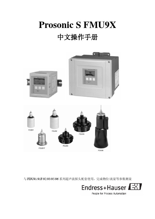
Prosonic S FMU9X中文操作手册与FDU91/91F/92/93/95/96系列超声波探头配套使用,完成物位/流量等参数测量物位测量中的应用:配备一个或两个超声波探头可对液体、糊状物、泥块、粉尘及表面粗糙的块状物料进行连续非接触式物位测量。
量程范围≦70m(根据不同的型号和使用场合决定测量范围);采用两个探头可完成差值、平均值以及总和的测量与计算。
流量测量中的应用:配备一个或两个超声波探头可对明渠和测量堰中的介质进行流量测量。
优点:六行纯文本液晶显示,简单的菜单引导式操作;自动识别FDU91/91F/92/93/95/96系列超声波探头,并且可与FDU8X系列探头配套使用;包络线显示可用于快速、简单的仪表故障判断;提供ToF-Tool-FieldTool Package 操作软件可使用户方便的对仪表进行操作、诊断和参数设定;内部预置常用的明渠/堰的流量测量线性化数据表,用户可根据情况自由选择,并根据线性化数据表计算流量;一、测量原理:BD:盲区;D:探头振膜表面到物料表面的距离;E:测量零点(0% ,空罐);F:最高物位(100% ,满罐);L:物位高度;V:物料的体积(或质量)探头向物料表面发射超声波脉冲信号。
物料表面反射回波,这部分回波又被探头所接收。
变送器计算探头发射和接收超声波脉冲信号的时间差t,由时间t和声速c可计算出探头振膜表面和物料表面的距离。
D=C * t/2通过计算出的D值可计算出理想状态下的物位L,体积V等。
1、盲区:物料的最高物位F不能进入盲区BD,传感器的特性决定了盲区内的回波信号将无法被接收到。
盲区的大小与所采用的探头型号有关。
2、干扰回波抑制:Prosonic S 具有干扰回波抑制功能,以确保干扰回波(如边缘,焊接点和安装过程造成的干扰)不会被误认为是实际的物位表面的反射回波信号。
3、物位测量的应用实例:4、通过HART的通讯连接:在标准型号中,HART信号是加载于第一输出电流之上的。
温度探头的选择及校准

• 水汽进入Pt100检测器 ,这会造成局部短路, 从而使测试值下降
蒸汽 +压力
要小心处理传感器 (1) 以延长其使用寿命 不要用力硬拉导线 ! 蒸汽+压力
不要在锋利的边缘周围拉扯线缆 !
要小心处理传感器 (2)
以延长其使用寿命
勿弯 折探针!
勿踩踏缆线或 让小车从上推过
细针式的传感器
• 直径3 毫米的针式探头可以穿透塞子 和器壁,以确保测量到软袋、玻瓶
和罐子内部的温度.
3 mm
• 双芯Pt100 传感器的直径为3毫米,
采用2×4的导线.
• 如灭菌容器中的内容物,关键问题 是测试内容物的温度,而不是外部
的温度
耐受蒸汽的传感器和线缆
• 高压高温蒸汽环境中, 探头、接合件和导线的 密封性十分重要。同时 ,导线最好柔软,便于 操作人员操作。
• 可见,不确定度、tolerance 在经较复杂的一系 列操作后能基本固定,而实际偏差则与每次测 量的状况直接相关,具有较大的可变性。
铂电阻定义和用途
• PT100是一个温度传感器,用白金(Pt)作成,是一种稳 定性和线性都比较好的铂丝热电阻传感器,可工作在 200℃ 至 650℃ 的范围。100表示它在0℃时电阻值为 100欧姆,在100℃时,约为138.5欧姆。
• 溯源国际温标 ITS-90,要求有以下知识... • …对实际温度的偏差 • …测量不确定度 • 有标准化的计算方法
– 应当理解可测量偏差(测定误差)与偶然误差之间的区别 – 测量误差 = 平均值-目标值 – (许多测试的不确定性形成正态分布。测试的二倍标准差即
是测定的不确定性。它大体上是所有测试值的95%。大约有 5%的结果会超出规定的不确定性以外。)见邮件
维萨拉工业测量产品手册说明书

维萨拉工业测量产品手册湿度 | 温度 | 露点 | 二氧化碳 | 沼气 | 油中水分 | 连续监测系统 |溶解气体分析系统 | 过氧化氢 | 压力 | 气象 | 服务支持观测让世界更美好维萨拉的工业测量业务领域产品能够帮助客户了解工艺过程。
我们的产品为客户提供准确可靠的测量数据,帮助客户做出优化工业过程的决策,从而提高过程效率、产品质量、生产力和产量,同时减少能源消耗、浪费和排放。
我们的监测系统还能帮助客户在受监管的环境中运营,以履行监管合规性。
维萨拉工业测量服务于多种类型的运营环境,从半导体工厂和高层建筑,到发电厂和生命科学实验室,对环境条件的可靠监测是实现成功运营的先决条件。
维萨拉的测量产品和系统广泛应用于监测温度、湿度、露点、气压、二氧化碳、汽化过氧化氢、甲烷、油中水、变压器油中溶解气体和液体浓度等参数。
我们的生命周期服务可在测量仪表的整个使用寿命内提供维护。
作为值得信赖的合作伙伴,我们通过在产品和系统生命周期中保证准确的测量数据来支持客户做出可持续的决策。
本产品目录对我们的产品进行整体的介绍,以帮助您选择适合您需求的产品。
如需更多信息,请通过以下方式联系我们:销售热线:400 810 0126电子邮箱:**********************公司网址:扫描二维码,关注维萨拉企业微信3目 录Indigo系列变送器Indigo200系列数据处理单元 (7)Indigo300数据处理单元 (9)Indigo510数据处理单元 (12)Indigo520数据处理单元 (15)用于抽检和校准的手持设备Indigo80手持式显示表头 (18)HMP80系列手持式湿度和温度探头 (21)DMP80系列手持式露点和温度探头 (23)HM70手持式湿度和温度仪 (26)HUMICAP® 手持式湿度温度仪表HM40系列 (29)DM70手持式露点仪 (33)MM70适用于现场检测的手持式油中微量水分和温度测试仪 (36)湿度和温度用于测量相对湿度的维萨拉HUMICAP® 传感器 (38)如何为高湿度应用选择合适的湿度仪表 (40)Insight PC机软件 (44)HMP1墙面式温湿度探头 (46)HMP3一般用途湿度和温度探头 (48)HMP4相对湿度和温度探头 (51)HMP5相对湿度和温度探头 (54)HMP7相对湿度和温度探头 (57)HMP8相对湿度和温度探头 (60)HMP9紧凑型湿度和温度探头 (63)TMP1温度探头 (66)适用于苛刻环境中湿度测量的HMT330系列温湿度变送器 (68)HMT370EX系列本安型温湿度变送器 (78)HMT310温湿度变送器 (84)HUMICAP® 温湿度变送器HMT120和HMT130 (87)适用于高性能暖通空调应用的HMW90系列湿度与温度变送器 (90)HMD60系列湿度和温度变送器 (92)HMD110/112和HMW110/112湿度和温度变送器 (96)适用于楼宇自动化高精度室外测量的HMS110系列温湿度变送器 (99)HMDW80系列温湿度变送器 (101)适用于楼宇自动化应用室外测量的HMS80系列温湿度变送器 (105)HMM100湿度模块 (107)适用于OEM应用的HMM105数字湿度模块 (109)HMM170温湿度模块 (111)INTERCAP® 温湿度探头HMP60 (113)4INTERCAP® 温湿度探头HMP63 (115)HUMICAP® 温湿度探头HMP110 (117)HUMICAP® 温湿度探头HMP113 (120)SHM40结构湿度测量套件 (122)HMK15湿度校准仪 (125)DTR500太阳辐射和雨水防护罩 (127)HMT330MIK气象安装套件 (129)适用于动力汽轮机进气测量的HMT300TMK汽轮机安装组件 (131)露点Vaisala DRYCAP® 传感器用于测量干燥过程中的湿度 (133)DMP5露点和温度探头 (135)DMP6露点探头 (138)DMP7露点和温度探头 (140)DMP8露点和温度探头 (142)DMT340系列露点和温度变送器 (145)适用于高温应用的DMT345和DMT346露点变送器 (151)DMT152露点变送器 (155)DMT143露点变送器 (157)DMT143L露点变送器 (160)用于冷冻干燥机的DMT132露点变送器 (162)DM70用DSS70A便携式采样系统和采样室 (164)DPT146露点和气压变送器 (166)DPT145多参数变送器 (168)二氧化碳适用于苛刻环境的维萨拉CARBOCAP® 测量传感器 (171)GMP343二氧化碳探头 (173)适用于CO2恒温箱的GMP231二氧化碳探头 (176)GMP251二氧化碳探头 (178)GMP252二氧化碳探头 (181)GM70手持式二氧化碳测试仪 (184)适用于苛刻通风要求应用的GMW90系列二氧化碳及温湿度变送器 (187)适用于智能控制通风系统 (DCV) 的GMW80系列二氧化碳、湿度和温度一体变送器 (190)按需控制通风系统中的GMD20系列二氧化碳变送器 (193)GMD110管道安装式二氧化碳变送器 (195)沼气MGP261多气体探头 (197)MGP262多气体探头 (199)油中水用于测量油中微水的维萨拉HUMICAP® 传感器 (201)MMP8油中水分探头 (203)MMT330系列油中微量水分与温度变送器 (205)5MMT310系列油中微量水分与温度变送器 (209)MMT162油中微量水分和温度变送器 (211)连续监测系统维萨拉viewLinc企业版服务器版本5.1 (213)AP10 VaiNet无线接入点 (215)用于连续监测系统的RFL100无线数据记录仪 (218)HMP115温湿度探头 (223)TMP115宽范围温度探头 (225)维萨拉温度与相对湿度数据记录仪系列DL2000 (227)维萨拉通用输入数据记录仪系列DL4000 (229)维萨拉多应用温度数据记录仪DL1016/1416 (231)维萨拉热电偶数据记录仪系列DL1700 (233)维萨拉中端温度、湿度及触点通道数据记录仪 (235)维萨拉vNet以太网供电数据记录仪接口 (238)溶解气体分析OPT100 Optimus™ 溶解气体分析(DGA)监测系统 (240)MHT410变压器油中微量水分、氢气和温度分析仪 (244)过氧化氢用于测量汽化过氧化氢、相对饱和度和相对湿度的维萨拉PEROXCAP® 传感器 (246)用于过氧化氢、湿度和温度测量的HPP270系列探头 (249)压力用于测量压力的维萨拉BAROCAP® 传感器 (253)PTU300气压、湿度和温度一体变送器 (255)适用于专业气象、航空与工业用户的PTB330数字式气压计 (260)气压传递标准PTB330TS (262)PTB210数字气压计 (265)PTB110气压计 (267)将风引起误差降低的SPH10/20静压头 (269)气象Vaisala用于工业应用测量的风和气象传感器技术 (271)风测量装置WA15 (273)WINDCAP® 超声波风传感器WMT700系列 (276)气象变送器WXT530系列 (278)服务支持面向仪表全生命周期服务 (280)67功能•数据处理单元 USB-C 端口支持使用通用 USB 电缆连接到维萨拉Insight PC 软件•数字和图形彩色显示屏(针对模拟型号提供可选的不带显示屏的款式)•IP65 外壳•24 V AC/DC 电源输入•Indigo201:3 个模拟输出(mA 或 V)•Indigo202:RS-485,带有Modbus ® RTU•2 个可配置的继电器维萨拉 Indigo200 系列数据处理单元是一种主机设备,它显示来自维萨拉 Indigo 兼容探头的测量值,同时也可通过模拟信号、Modbus RTU 通信或继电器将这些测量值传输到自动化系统。
物性探头一览表

A/DP
还评价饼干面团的硬度(稠度)特性。还可以 评价酵母的发酵力。
31 膜类产品
A/TG
拉伸装置,测量样品(食用膜,包装材料,口 香糖,铝膜)拉伸强度
特性变化情况即“bown life”特性
13 果蔬系列
P/5 测试样品的表皮硬度和果肉坚实度
14 肉制品系。对样品进行压缩 操作。评价水果的屈服强度,火腿肠和肉丸制 品的硬度和弹性等指标。
15 肉制品系列
HDP/BS
肉嫩度标准测试附件,包括两组刀头,分别为 Warner Bratzler 刀头和平装刀头,符合 USDA 和国家肉嫩度检测标准要求
回复性和弹性。
25
面团及面制品
HDP/3PB
三点弯曲测试装置,测断裂强度。测量蔬菜的 新鲜度和饼干,巧克力棒等产品的断裂强度。
26 面团及面制品
A/KIE
微型拉伸仪,测量面团和面筋的拉伸特性。包 括面团拉伸阻力,面团延伸度,拉伸功等技术 参数。为制团工艺,添加剂(氧化剂,盐乳化 剂和酶)的使用提供基础数据
8 通用探头系列
P/45C
45°锥形探头,检测固体样本延展性和涂布性。 评价黄油的硬度指标。
9 通用探头系列 P/60C 60°锥形探头
10 通用探头系列 P/0.25S 球型探头
11 通用探头系列 P/1S 球型探头
10 刀片剪切刀具,测试压力、剪切、挤压的混 12 通用探头系列 HDP/KS10 合操作,还用于早餐谷物食品,评价其浸水后
27
面团及面制品
A/LKB-F
评价面条硬度。符合谷物化学家协会标准 AACC16-50
28
面团及面制品
HDP/CFS
脆性断裂支撑台,测量脆性食品的酥脆性,例 如脆片。测量玉米脆片特性,符合 AIB 标准。
Omega OM-90系列胶囊温度与湿度数据记录仪用户指南说明书

e-mail:**************For latest product manuals: OM-90 SERIESPortable Temperature andShop online at User’s Gui d e***********************Servicing North America:U.S.A. Omega Engineering, Inc.Headquarters: Toll-Free: 1-800-826-6342 (USA & Canada only)Customer Service: 1-800-622-2378 (USA & Canada only)Engineering Service: 1-800-872-9436 (USA & Canada only)Tel: (203) 359-1660 Fax: (203) 359-7700e-mail:**************For Other Locations Visit /worldwideUser GuideContents1. Document Overview (3)2. Product Overview (4)3. Technical Specifications (6)4. Buttons and LED Indicators (7)5. Packaging List (8)6. Installation of the Software (9)7. Using the Software (10)7.1. Front Page (10)7.2. Main Page (11)7.3. Configuration of a Data Logger (Start on Disconnection) (12)7.4. Saving a Configuration File (14)7.5. Loading a Configuration from File (15)7.6. Retrieving Logged Data (16)7.7. Viewing Logged Data from File (17)7.8. Configuration of a Data Logger (Start at Specified Time) (19)7.9. Configuration of a Data Logger (Start using Button Press) (20)7.10. Configuration of a Data Logger (Real Time Logging) (21)8. Mounting Guidelines (22)9. Battery Replacement (22)10. Technical Support (22)1.Document OverviewThis guide is provided to distribute the following information:∙the main features of data logger∙how to install the software for the logger∙how to use the software for configuration, data extraction and data viewing ∙how to mount your data logger∙how to replace the battery for the data logger∙contact information should you have further technical questions2.Product OverviewThe OM-90 Series are compact temperature / humidity data loggers measuring just 35mm x 60mm x15mm. These data loggers are commonly used in transport applications including but not limited to transport of:∙sensitive/fragile items∙food∙animal/livestock∙plants∙chemicals∙medicines or organsThe OM-90 Series comes in two versions; OM-91 is a temperature only version and OM-92 is a temperature and humidity logger. This document applies for both versions.Figure 1: Introducing the OM-90 Series Data Loggers and softwareSuppose for example you would like to transport some delicate or fragile cargo from one location to another. By attachment of a data logger one can record temperature and humidity conditions during the journey. At the destination you can then extract the logged data using very simple software and see graphically or in raw data format the changes in environment over time.When you would like to guarantee that items are transported within particular environmental limits then one can also set operating ranges above or below which light indicators will be activated so that the user can become aware that the desired transportation conditions have been exceeded.Figure 2: Data Logger IndicatorsThe data logger offers accurate and repeatable logging for temperature and relative humidity. Temperature is measured to an accuracy of +0.3o C over the range +5o C to +60o C. Over the full range -30o C to +80o C the accuracy is +2.0o C. Relative humidity is measured to an accuracy of +2.0% over 20% to 80% humidity range and +3.0% over 0% to 100%. Both temperature and relative humidity are logged at a user configurable logging rate which can be set in software.The data logger is equipped with the largest logging memory when compared with comparable portable logging devices currently available. The data logger has provision for an impressive 65520 records, each of which is a time-stamped recording of temperature and humidity.-30o C to +80o C (-22o F to 176o F)+0.3o C (+5o C to +60o C)+0.5o F (41o F to 140o F)see accuracy curve in figure 30.01o C (0.2o F)0% to 100%+2.0% (20% to 80%)see accuracy curve in figure 30.01%CR2540 coin cellup to 4 years while logging 35mm x 60mm x 15mm16 characters3.Technical Specifications∙Temperature range∙Temperature accuracy (limited range)∙Temperature accuracy (-30o C to +80o C)∙Temperature resolution∙Humidity range (only on OM-92)∙Relative humidity accuracy (limited range)∙Relative humidity accuracy (0% to 100%)∙Relative humidity resolution∙Temperature alarms (minimum & maximum)∙Relative humidity alarms (minimum & maximum)∙Battery ∙Battery life ∙Physical size∙Software available on Windows XP, Vista, Windows 7, 8 & 10 (coming soon to Linux & MacOs)∙Logger identifier∙Logging space (includes time plus temperature & humidity) 65520 pointsFigure 3: Temperature and Humidity Accuracy4.Buttons and LED IndicatorsThe data logger includes one button located on the side of the logger. It is possible by configuration in the software to use this button as a way to start and stop logging. See section 7.9 Configuration of a Data Logger (Start using Button Press)Figure 4: Data Logger Start/Stop ButtonThe logger contains two LED indicators - LED left and LED right with the following functionality:Status LED∙When the logger starts logging then this LED pulses green once for 1 second.∙When logging this LED pulses green for 7 milliseconds and off for 6 seconds.∙When the logger stops then this LED pulses red for 1 second then off forever.Alarm LED∙When a temperature or humidity alarm is triggered this LED pulses red for 7 milliseconds and off for 6 seconds.Figure 5: Data Logger LED indicators5.Packaging ListYour data logger comes standard with the following items.∙One Data Logger unit (either OM-91 or OM-92)Figure 6: Data Logger Unit∙One CR2450 coin cell batteryFigure 7: CR2450 Coin Cell Battery and Install CD∙One USB cable – type A to micro-USB type BFigure 8: USB CableOne installation CD (Software is also available for download on the OM-90 web page)6.Installation of the SoftwareInstallation of the software is very simple. The data logger needs no special drivers since it is a USB HIDdevice and such devices can make use of the standard drivers that come with Windows. Simply install the software from the CDOR download and install the software from Omega's OM-90 web page. (look for the software icon). included with the data logger.In order to use this software consult the next section – Section 7 "Using the Software".ing the Software7.1.Front PageWhen the software is started the welcome screen appears and gives a brief introduction to the data loggers and what they can be used for.∙Click on the Configuration Wizard Button to start configuration of the logger.∙Click on the Graph Button if you want to view data graphically.∙Click on the Raw Data Button if you want to view logger data as a table.Figure 9: OM-90 Series Data Logger Software7.2.Main PageThe main page of the software consists of a configuration pane, a graphical pane and a spreadsheet pane. It is possible to have any of these enabled or disabled by the buttons located top left in the window. The panes will automatically start in an enabled or disabled view depending on the viewing mode select from the front page.Figure 10: Software Main PageButtons are also included for saving/loading configuration and logged data to and from file.There is also a button for selection between Celsius or Fahrenheit temperature scales.A connection indication on the right hand side becomes blue when your application is connected to a data logger and is greyed-out otherwise.Finally a home icon provides a link back to the front page.7.3.Configuration of a Data Logger (Start on Disconnection)Configuration of the data logger starts by specifying the device name. Up to 16 characters is allowed in the name.Figure 11: Configuration Step (Start on Disconnection)Next select the logger start to On Disconnection. There are other options (At Specified Time, Button Press and Real Time Logging) which will be discussed in later sections of this manual.Select the logging interval (this is the time between samples).For temperature logging then one needs to enable or disable the logging. In the case the temperature logging is enabled then one can also set alarm thresholds for which the alarm indication will signify that temperature limits have been exceeded.Similarly for humidity one needs to enable or disable the logging and configure the alarm limits.Finally to save the configuration setup to the data logger, press the Configure Button.Figure 12: Write Configuration to the LoggerOnce configured the software will show the logger time will be synchronized to the PC time. The logger firmware revision will also appear in the application.Once you disconnect the logger from the PC, logging will start automatically and at the configured logging interval. A green light will flash every 6 seconds to indicate that the unit is logging. The red light will flash also in the case that the temperature or humidity goes outside of the allowed limits and triggers the alarms.If the logger becomes full then all lights will stop flashing.7.4.Saving a Configuration FileConfigurations can be saved to file so that you can use the configuration next time or if you have multiple devices with the same configuration.Saving a configuration file is just a matter of selecting the save icon and filling out the file name. If the logger contains no logged data then it will only save the configuration settings. Configuration and logged data is stored in Comma Separated Value (CSV) format.Figure 13: Saving a Configuration to File7.5.Loading a Configuration from FileLoading a configuration file from disk is just a matter of selecting the open icon and selecting the configuration file name. This upload presents a simple way to configure multiple loggers with the same configuration. This ensures a common configuration and saves time/effort when configuring multiple devices.Figure 14: Loading a Configuration from FileRemember to press the configuration button if you want the configuration data held in the software to be written to your data logger.7.6.Retrieving Logged DataData can be retrieved from the logger by connecting to the logger and then pressing the read button at the bottom left of the software.Both the device configuration and logged data will immediately become uploaded and viewable in the configuration, graphical and spreadsheet views.Zooming in and out of the graphs can be achieved by the following controls:∙To Zoom In - Drag the left mouse button∙To Zoom Out - Click the right mouse button∙When zoomed in you can move around using the key-board arrows or the mouse scroll wheel To write data and configuration to file, press the save icon. Data and configuration is then stored in Comma Separated Value (CSV) format which can be edited by third party software such as Microsoft Excel or read back into the data logger software at a later point.Figure 15: Saving Logged Data to File7.7.Viewing Logged Data from FileIt is a simple matter to read back data from file (CSV format) into the software and view previous logs graphically or using the spreadsheet views. Simply press the open icon and then select the file which you would like to view.Figure 16: Retrieving Logged Data from FileFigure 17: Retrieving Logged Data from File (complete)7.8.Configuration of a Data Logger (Start at Specified Time)You can configure a device so that it starts at a specific time. Configure as per section 7.3 but select At Specified Time. Fill in the exact month, day, hour, minute and seconds when you want the logging to start.Remember to write the setup to the logger by pressing the Configure Button.When you have disconnected the logger and the time reaches the desired start time for the logging then the logger will begin to log. This is a perfect way to have multiple loggers start logging at exactly the same time.Figure 18: Configuration Step (Start at Specified Time)7.9.Configuration of a Data Logger (Start using Button Press)You can also configure the device so that it starts logging on a button press. Configure as per section 7.3 but select Button Press.Remember to write the setup to the logger by pressing the Configure Button.When you have disconnected the logger you can start logging by a simple button press. You will then see it is logging because the green light starts flashing every 6 seconds. You can also stop it using a button press – and all lights will stop flashing.Figure 19: Configuration Step (Start using Button Press)7.10.Configuration of a Data Logger (Real Time Logging)You may also use your data logger in Real Time Logging mode. Select the start logging to Real Time Logging with the appropriate logging interval. Next press start. You will then see the software take samples from the logger directly and display them on the table and graphs. This is a way to monitor temperature and humidity conditions directly from your PC instead of using the remote logging.Figure 20: Configuration Step (Real Time Logging)8.Mounting GuidelinesThere is no particular limitation with regard to transporting your data logger. The logger may be fastened to a transportation container or loosely packed.It is recommended however to keep some air space around the ventilation slots on the logger or else the logger may take longer to track humidity and temperature changes.9.Battery ReplacementYour data logger uses a CR2450 3V Lithium-Ion battery.In order to replace the battery:∙First un-mount the logger.∙Next the cover needs to unscrewed and removed.∙The old battery should then be removed and a new battery inserted. Please try not to touch any exposed electronics in the process.∙Finally attach the cover again with screws.10.Technical SupportFor technical support questions please contact Omega at:1-800-USA-WHEN (1-800-872-9436)*************************OMEGA’s policy is to make running changes, not model changes, whenever an improvement is possible. T his affords our customers the latest in technology and engineering.OMEGA is a registered trademark of OMEGA ENGINEERING, INC.© Copyright 2017 OMEGA ENGINEERING, INC. All rights reserved. T his document may not be copied, photocopied, FOR WARRANTY RETURNS, please have the following information available BEFORE contacting OMEGA:1. P urchase Order number under which the product was PURCHASED,2. M odel and serial number of the product under warranty, and3. Repair instructions and/or specific problems relative to the product.FOR NON-WARRANTY REPAIRS, consult OMEGA for current repair charges. Have the following information available BEFORE contacting OMEGA:1. Purchase Order number to cover the COST of the repair,2. Model and serial number of the product, and 3. Repair instructions and/or specific problems relative to the product.RETURN REQUESTS/INQUIRIESDirect all warranty and repair requests/inquiries to the OMEGA Customer Service Department. BEFORE RET URNING ANY PRODUCT (S) T O OMEGA, PURCHASER MUST OBT AIN AN AUT HORIZED RET URN (AR) NUMBER FROM OMEGA’S CUST OMER SERVICE DEPART MENT (IN ORDER T O AVOID PROCESSING DELAYS). The assigned AR number should then be marked on the outside of the return package and on any correspondence.T he purchaser is responsible for shipping charges, freight, insurance and proper packaging to preventbreakage in transit.WARRANTY/DISCLAIMEROMEGA ENGINEERING, INC. warrants this unit to be free of defects in materials and workmanship for a period of 13 months from date of purchase. OMEGA’s WARRANTY adds an additional one (1) month grace period to the normal one (1) year product warranty to cover handling and shipping time. This ensures that OMEGA’s customers receive maximum coverage on each product.If the unit malfunctions, it must be returned to the factory for evaluation. OMEGA’s Customer Service Department will issue an Authorized Return (AR) number immediately upon phone or written request. Upon examination by OMEGA, if the unit is found to be defective, it will be repaired or replaced at no charge. OMEGA’s WARRANT Y does not apply to defects resulting from any action of the purchaser, including but not limited to mishandling, improper interfacing, operation outside of design limits, improper repair, or unauthorized modification. T his WARRANT Y is VOID if the unit shows evidence of having been tampered with or shows evidence of having been damaged as a result of excessive corrosion; or current, heat, moisture or vibration; improper specification; misapplication; misuse or other operating conditions outside of OMEGA’s control. Components in which wear is not warranted, include but are not limited to contact points, fuses, and triacs.OMEGA is pleased to offer suggestions on the use of its various products. However, OMEGA neither assumes responsibility for any omissions or errors nor assumes liability for any damages that result from the use of its products in accordance with information provided by OMEGA, either verbal or written. OMEGA warrants only that the parts manufactured by the company will be as specified and free of defects. OMEGA MAKES NO OTHER WARRANTIES OR REPRESENTATIONS OF ANY KIND WHATSOEVER, EXPRESSED OR IMPLIED, EXCEPT THAT OF TITLE, AND ALL IMPLIED W ARRANTIES INCLUDING ANY W ARRANTY OF MERCHANTABILITY AND FITNESS FOR A PARTICULAR PURPOSE ARE HEREBY DISCLAIMED. LIMITATION OF LIABILITY: The remedies of purchaser set forth herein are exclusive, and the total liability of OMEGA with respect to this order, whether based on contract, warranty, negligence, indemnification, strict liability or otherwise, shall not exceed the purchase price of the component upon which liability is based. In no event shall OMEGA be liable for consequential, incidental or special damages.CONDITIONS: Equipment sold by OMEGA is not intended to be used, nor shall it be used: (1) as a “Basic Component” under 10 CFR 21 (NRC), used in or with any nuclear installation or activity; or (2) in medical applications or used on humans. Should any Product(s) be used in or with any nuclear installation or activity, medical application, used on humans, or misused in any way, OMEGA assumes no responsibility as set forth in our basic WARRANT Y /DISCLAIMER language, and, additionally, purchaser will indemnify OMEGA and hold OMEGA harmless from any liability or damage whatsoever arising out of the use of theProduct(s) in such a manner.Where Do I Find Everything I Need for Process Measurement and Control?OMEGA…Of Course!Shop online at TEMPERATUREM U Thermocouple, RTD & Thermistor Probes, Connectors,Panels & AssembliesM U Wire: Thermocouple, RTD & ThermistorM U Calibrators & Ice Point ReferencesM U Recorders, Controllers & Process MonitorsM U Infrared PyrometersPRESSURE, STRAIN AND FORCEM U Transducers & Strain GagesM U Load Cells & Pressure GagesM U Displacement TransducersM U Instrumentation & AccessoriesFLOW/LEVELM U Rotameters, Gas Mass Flowmeters & Flow ComputersM U Air Velocity IndicatorsM U Turbine/Paddlewheel SystemsM U Totalizers & Batch ControllerspH/CONDUCTIVITYM U pH Electrodes, Testers & AccessoriesM U Benchtop/Laboratory MetersM U Controllers, Calibrators, Simulators & PumpsM U Industrial pH & Conductivity EquipmentDATA ACQUISITIONM U Communications-Based Acquisition SystemsM U Data Logging SystemsM U Wireless Sensors, Transmitters, & ReceiversM U Signal ConditionersM U Data Acquisition SoftwareHEATERSM U Heating CableM U Cartridge & Strip HeatersM U Immersion & Band HeatersM U Flexible HeatersM U Laboratory HeatersENVIRONMENTALMONITORING AND CONTROLM U Metering & Control InstrumentationM U RefractometersM U Pumps & TubingM U Air, Soil & Water MonitorsM U Industrial Water & Wastewater TreatmentM U pH, Conductivity & Dissolved Oxygen Instruments。
OMEGA TX90系列温度传感器传输器说明书

N-39To OrderTX92-6 transmitter shown with optional RT mounting track and optional TX90-BRmounting bracket. Shown actual size.Miniature Temperature TransmittersThermocouple or RTD (Pt100) InputU Metal Case, RFI Shield U 2-Wire Transmitter U 4 to 20 mA Output U ±0.1% FS AccuracyUUpscale Break Protection U Non-IsolatedU Mounts in Protection HeadThe economical OMEGA ® TX91 and TX92 2-wire transmitters provide an output current of 4 to 20 mA, and are proportional to the mV signal of athermocouple or to a 2- or 3-wire RTD sensor input.The TX91 or TX92 are very compact and can mount directly within the OMEGA NB1 cast iron protection head. By having the transmitter near the sensor, the effects of electrical noise can be minimized and long runs of thermocouple wire can be eliminated.SpecificationsOutput Range: 4 to 20 mA DCZero and Span Adjustment Range: ±25%Accuracy: ±0.1% FS (includes effects of linearity, hysteresis and repeatability) referenced to the mV inputAmbient Temperature Range: -32 to 85°C (-25 to 185°F)Storage Temperature Range: -65 to 90°C (-85 to 193°F)Supply Voltage: 11 to 44 Vdc; 24 Vdc recommended Max Loop Vs – 11 V Resistance: 0.020ADimensions: 29 H x 45 mm D (1.125 x 1.75") (height includes terminal strip)Weight: 50 g (1.5 oz)T/C. Not linearized to temperature. (2) Non-Isolated unit for use with ungrounded probes.NB1TX shown with optional thermowell.NI/I/2/ABCD TX91 & TX92Entity Parameters Vmax. = 30 V Imax = 150 mACi = OµfOrdering Example: NB1TX-K6, TX91 transmitter for Type K thermocouple, 0 to 1000°F output range. Transmitter housed in NB1-CASS-14U-12 Type K probe.For complete information on NB1 thermocouple probes and PR-12 RTD probes, see 。
岛电90系列说明书

四. 用户的基本设置窗口
1) 传感器类型和范围/单位 [1-48]/[1-49]窗口
2) 调节输出正/反作用 [1-42]窗口
3)SSR(P型)和继电器接点(Y型)的输出比例周期 [1-10]窗口
七.选件功能
1) 设定值偏移(双设定):在[0-6]窗口修改SB数值,当调节器外部端子接点闭合时,仪表的设定值为[0-0]窗口的SV+SB,此时面板的SB/COM灯亮。接点断开后SB撤消,为[0-0]的SV值。SB可用于双设定值间的快速选择,例如:温室的白昼控制,加热系统的预热或保温用途。
2) 模拟变送输出(不能与通讯同时选择)
C.当测量值在设定值上下缓慢波动时,可适当增加积分时间或增大比例带。
D.当测量值在设定值上下频繁波动时,可适当减小微分时间。
PID算法外的其他方式:
手动更改PID参数设定窗口,有下述的调节方式:
位式调节:当P=OFF时,积分I和微分D参数被自动取消,出现位式灵敏度调整参数DF,用于调整位式动作宽度,例如:反作用时,设定值500℃,灵敏度10℃,“Y”型调节继电器接点在505℃时关断,在495℃或低于495℃时吸合。
输出限幅:可设对应PID号的输出下限O-L(0~99%)和上限O-H(1~100%)。例如: O-L设 20%和O-H 设80%,对应0~10V和4~20mA分别是2~8V和7.2~ 16.8mA。适用于限定阀门开度,避开如线性阀的非线性区,伺服动作范围、减小加热功率以及对特殊加热元件某升温段的功率限制等。限幅虽能减小超调,如果因调节量不足将影响调节速度造成欠调(如长时间温度不能到达)。对反作用的加热,会因维持下限输出造成连续超调,一般不设下限(0.0%)。
YCAC主要零部件手册

YCAC系列风冷冷水机组PARTS MANUAL约克广州空调冷冻设备有限公司机组的爆炸图及主要零部件清单YCAC 06/10 PACKYCAC 06 PACK系列NUMBER REMARK NO. DESCRITION Qty/Set PART1 板式换热器 CB52-14H(ALFA) 1 026G00073A0062 Y 型水过滤器 DN25(1" 50 目 ) 1 026G00080-007 随机附件3 NTC2M 温度传感器(改进外套) 3 035G00037-0194 TEV TDEX3 068H4151 DANFOSS 1 022G00002-0115 压缩机 COPELAND ZR40K3-PFJ 1 015G00001-0356 风扇 FB045-6EA.4C.2P 1 026G00072-0017 安全阀 G1/2" 6BAR 4615C60 1 022G00011-0018 自动补水阀 G1/2" 3110C12 1 022G00012-0019 自动放气阀 G3/8" 2161C38 2 022G00013-00110 微型球阀 G3/8" 1 022G00014-001 随机附件11 靶式流量开关 LKB-01BB 1 024G00009-002 随机附件12 H20PS 压力开关 2.8MPA 1 024G00013-006 高压侧13 H20PS 压力开关 0.05MPA 1 024G00013-007 低压侧14 水压差控制器 SFS 1-105 1 024G00015-00115 干燥过滤器 C-084-S 1 026G00029-01116 水泵 UPS25-80 ( 格兰富单相 ) 1 026G00071-00617 YCAC06PACK 水箱总成 1 362G55597-00218 高迪亚电路板 3PH-210 B型 1 025G00055-00919 高迪亚手操器 3PH-200 B型 1 025G00056-002YCAC 10 PACK系列NUMBER REMARK NO. DESCRITION Qty/Set PART1 热交换器 SWEP B25/22 1 026G00073A0012 Y 型水过滤器 DN25(1" 50 目 ) 1 026G00080-007 随机附件3 NTC2M 温度传感器(改进外套) 3 035G00037-0194 TEV TDEX4 068H4152 DANFOSS 1 022G00002-0125 谷轮压缩机 ZR47K3-PFJ-522 1 015G00001-0426 风扇 FB056-8EA.4F.2P 1 026G00072-0027 安全阀 G1/2" 6BAR 4615C60 1 022G00011-0018 自动补水阀 G1/2" 3110C12 1 022G00012-0019 自动放气阀 G3/8" 2161C38 2 022G00013-00110 微型球阀 G3/8" 1 022G00014-001 随机附件11 靶式流量开关 LKB-01BB 1 024G00009-002 随机附件12 H20PS 压力开关 2.8MPA 1 024G00013-006 高压侧13 H20PS 压力开关 0.05MPA 1 024G00013-007 低压侧14 水压差控制器 SFS 1-105 1 024G00015-00115 干燥过滤器 C-084-S 1 026G00029-01116 TOP-S30/10( 单相 ) 1 026G00071-00717 YCAC10B/10/12PACK 水箱总成 1 362G55597-00318 高迪亚电路板 3PH-210 B型 1 025G00055-00919 高迪亚手操器 3PH-200 B型 1 025G00056-002YCAC15--23YCAC 15系列NUMBER REMARK NO. DESCRITION Qty/Set PART1 热交换器 SWEP B25/22 1 026G00073A0012 Y 型水过滤器 DN25(1" 50 目 ) 1 026G00080-007 随机附件3 NTC2M 温度传感器(改进外套) 3 035G00037-0194 NTC3M 温度传感器(改进外套) 1 035G00037-017 热泵机组用,翅片感温探头5 压缩机 H23A62QDBEA 1 015G00001-0186 风扇 FB045-6EA.4C.2P 2 026G00072-0017 安全阀 G1/2" 6BAR 4615C60 1 022G00011-001 PACK机组用8 自动补水阀 G1/2" 3110C12 1 022G00012-001 PACK机组用9 自动放气阀 G3/8" 2161C38 2 022G00013-001 PACK机组用10 微型球阀 G3/8" 1 022G00014-001 PACK机组用,作为附件11 靶式流量开关 LKB-01BB 1 024G00009-002 随机附件12 H20PS 压力开关 2.8MPA 1 024G00013-006 高压侧13 H20PS 压力开关 0.05MPA 1 024G00013-007 低压侧14 水压差控制器 SFS 1-105 1 024G00015-00115 四通阀 VH40100) 1 025G00039-020 热泵机组用16 平衡贮液器 1.7L 1 026G00067A001 热泵机组用17 汽液分离器 5-8 匹 M10 1 026G00069A002 热泵机组用18 水泵 CH4-30 ( 格兰富 ) 三相 1 026G00071-012 格兰富水泵(PACK机组用)19 水泵 TOP-S30/10 ( 三相 ) 1 026G00071-001 WILO立式水泵(PACK机组用)20 YCAC15 水箱总成 1 362G55597-004 带PACK 的WILO 水泵机组用 21 YCAC15 PL/HPL 水箱总成 1 362G55597-009 带PACK 的格兰富水泵机组用 22 高迪亚电路板 3PH-212 B 型 1 025G00055-008 23 高迪亚手操器 3PH-200 B 型 1 025G00056-002YCAC 23系列NO. DESCRITION Qty/Set PART NUMBERREMARK1 热交换器 SWEP B25/341 026G00073A0022 Y 型水过滤器 DN25(1" 50 目 1 026G00080-007 随机附件3 NTC2M 温度传感器(改进外套) 3 035G00037-0194 NTC3M 温度传感器(改进外套) 1 035G00037-017 热泵机组用,翅片感温探头5 压缩机 H2BG094DBEE 1 015G00001-0196 风扇 FB045-6EA.4C.2P 2 026G00072-0017 安全阀 G1/2" 6BAR 4615C60 1 022G00011-001 PACK 机组用 8 自动补水阀 G1/2" 3110C12 1 022G00012-001 PACK 机组用 9 自动放气阀 G3/8" 2161C38 2 022G00013-001 PACK 机组用10 微型球阀 G3/8" 1 022G00014-001 PACK 机组用,作为附件 11 靶式流量开关 LKB-01BB 1 024G00009-002 随机附件 12 H20PS 压力开关 2.8MPA 1 024G00013-006 高压侧 13 H20PS 压力开关 0.05MPA 1 024G00013-007 低压侧 14 水压差控制器 SFS 1-105 1 024G00015-00115 四通阀 VH60100(RANCO JAPAN) 1 025G00039-022 热泵机组用 16 平衡贮液器 3L 1 026G00067A002 热泵机组用 17 汽液分离器 5-8 匹 M10 1 026G00069A002 热泵机组用18 水泵 CH4-30 ( 格兰富 ) 三相1 026G00071-012格兰富水泵(PACK 机组用) 19 水泵TOP-S50/10 (三相) 1 026G00071-002WILO 立式水泵(PACK 机组用)20 YCAC23 水箱总成 1 362G55597-005 PACK 机组用 21 高迪亚电路板 3PH-212 B 型 1 025G00055-008 22 高迪亚手操器 3PH-200 B 型 1 025G00056-002YCAC30--90YCAC 30系列NUMBER REMARK NO. DESCRITION Qty/Set PART1 热交换器 SWEP B25/22 2 026G00073A0012 Y 型水过滤器 DN25(1" 50 目 1 026G00080-007 随机附件3 NTC2M 温度传感器(改进外套)4 035G00037-0194 NTC3M 温度传感器(改进外套) 2 035G00037-017 热泵机组用,翅片感温探头5 压缩机 H23A62QDBEA 2 015G00001-0186 风扇 FB056-8EA.4F.2P 2 026G00072-0027 安全阀 G1/2" 6BAR 4615C60 1 022G00011-001 PACK机组用8 自动补水阀 G1/2" 3110C12 1 022G00012-001 PACK机组用9 自动放气阀 G3/8" 2161C38 2 022G00013-001 PACK机组用10 微型球阀 G3/8" 1 022G00014-001 PACK机组用,作为附件11 靶式流量开关 LKB-01BB 1 024G00009-002 随机附件12 H20PS 压力开关 2.8MPA 2 024G00013-006 高压侧13 H20PS 压力开关 0.05MPA 2 024G00013-007 低压侧14 水压差控制器 SFS 1-105 1 024G00015-00115 四通阀 VH40100 2 025G00039-020 热泵机组用16 平衡贮液器 1.1L 2 026G00067A005 热泵机组用17 汽液分离器 5-8 匹 M10 2 026G00069A002 热泵机组用18 水泵 MHI 403( 三相 ) 1 026G00071-023 WILO 卧式水泵(PACK机组用)19 水泵 CH4-40 ( 格兰富 )三相 1 026G00071-004 格兰富水泵(PACK机组用)026G00071-002 WILO立式水泵(PACK机组用)20 水泵TOP-S50/10 (三相) 1PACK机组用362G55597-00621 YCAC30 水箱总成 122 高迪亚电路板 3PH-212 B型 1 025G00055-00823 高迪亚手操器 3PH-200 B型 1 025G00056-002YCAC 45系列NUMBER REMARK NO. DESCRITION Qty/Set PART1 热交换器 SWEP B25/342 026G00073A0022 Y 型水过滤器 DN40(1-1/2"50 目 1 026G00080-008 随机附件3 NTC2M 温度传感器(改进外套)4 035G00037-0194 NTC3M 温度传感器(改进外套) 2 035G00037-017 热泵机组用,翅片感温探头5 压缩机 H2BG094DBEE 2 015G00001-0196 风扇 FB063-8EA.4I.2P 2 026G00072-0037 安全阀 G1/2" 6BAR 4615C60 1 022G00011-001 PACK机组用8 自动补水阀 G1/2" 3110C12 1 022G00012-001 PACK机组用9 自动放气阀 G3/8" 2161C38 2 022G00013-001 PACK机组用10 微型球阀 G3/8" 1 022G00014-001 PACK机组用,作为附件11 靶式流量开关 LKB-01BB 1 024G00009-002 随机附件12 H20PS 压力开关 2.8MPA 2 024G00013-006 高压侧13 H20PS 压力开关 0.05MPA 2 024G00013-007 低压侧14 水压差控制器 SFS 1-105 1 024G00015-00115 四通阀 VH60100(RANCO JAPAN) 2 025G00039-022 热泵机组用16 平衡贮液器 2.4L 2 026G00067A004 热泵机组用17 汽液分离器 5-8 匹 M10 2 026G00069A002 热泵机组用18 水泵 MHI 405( 三相 ) 1 026G00071-026 WILO 卧式水泵(PACK机组用)19 水泵 CH4-50( 格兰富 )三相 1 026G00071-013 格兰富水泵(PACK机组用)20 水泵TOP-S50/10 (三相) 1026G00071-002 WILO立式水泵(PACK机组用)362G55597-007PACK机组用21 YCAC45 水箱总成 122 高迪亚电路板 3PH-212 B型 1 025G00055-00823 高迪亚手操器 3PH-200 B型 1 025G00056-002YCAC 60系列NUMBER REMARK NO. DESCRITION Qty/Set PART1 热交换器 SWEP B25-502 026G00073A0032 Y 型水过滤器 DN40(1-1/2"50 目 1 026G00080-008 随机附件3 NTC2M 温度传感器(改进外套)4 035G00037-0194 NTC3M 温度传感器(改进外套) 2 035G00037-017 热泵机组用,翅片感温探头5 压缩机 H2BG124DBEE 2 015G00001-0026 风扇 FB063-6EA.4I.2P 2 026G00072-0047 TEV TDEX12.5 68H4165 DANFOSS2/4022G00002-006 单冷2个,热泵4个8 干燥过滤器 C-084-S 2/4026G00029-011 单冷2个,热泵4个9 靶式流量开关 LKB-01BB 1 024G00009-002 随机附件10 H20PS 压力开关 2.8MPA 2 024G00013-006 高压侧11 H20PS 压力开关 0.05MPA 2 024G00013-007 低压侧12 水压差控制器 SFS 1-105 1 024G00015-00113 四通阀 VH60100(RANCO JAPAN) 2 025G00039-022 热泵机组用14 平衡贮液器 5.2L 2 026G00066A001 热泵机组用15 汽液分离器 10-15 匹 2026G00069A001 热泵机组用16 高迪亚电路板 3PH-212 B型 1 025G00055-008 不是联控主机17 高迪亚手操器 3PH-200 B型 1 025G00056-002 不是联控主机18 模块控制板Mcb-8(双机热泵) 1 024G00019-007 联控主机YCAC 75系列NUMBER REMARK NO. DESCRITION Qty/Set PART1 热交换器 SWEP V25/502 026G00073A0042 Y 型水过滤器 DN50(2"50 目 ) ) 1 026G00080-009 随机附件3 NTC2M 温度传感器(改进外套)4 035G00037-0194 NTC3M 温度传感器(改进外套) 2 035G00037-017 热泵机组用,翅片感温探头5 压缩机 H25G144DBEE 2 015G00001-0036 风扇 FB063-6EA.4I.2P 2 026G00072-0047 TEV TDEX12.5 68H4165 DANFOSS 2/4022G00002-006 单冷2个,热泵4个8 干燥过滤器 C-084-S 2/4026G00029-011 单冷2个,热泵4个9 靶式流量开关 LKB-01BB 1 024G00009-002 随机附件10 H20PS 压力开关 2.8MPA 2 024G00013-006 高压侧11 H20PS 压力开关 0.05MPA 2 024G00013-007 低压侧12 水压差控制器 SFS 1-105 1 024G00015-00113 四通阀 VH60100(RANCO JAPAN) 2 025G00039-022 热泵机组用14 平衡贮液器 8.6L 2 026G00066A002 热泵机组用026G00069A001 热泵机组用15 汽液分离器 10-15 匹 216 高迪亚电路板 3PH-212 B型 1 025G00055-008 不是联控主机17 高迪亚手操器 3PH-200 B型 1 025G00056-002 不是联控主机18 模块控制板Mcb-8(双机热泵) 1 024G00019-007 联控主机YCAC 90系列NO. DESCRITION Qty/Set PARTNUMBER REMARK1 热交换器 SWEP B45/302 026G00073A0052 Y 型水过滤器 DN50(2"50 目 ) ) 1 026G00080-009 随机附件3 NTC2M 温度传感器(改进外套)4 035G00037-0194 NTC3M 温度传感器(改进外套) 2 035G00037-017 热泵机组用,翅片感温探头5 DANFOSS SM185 压缩机 2 015G00001-076 用于涡旋压缩机机组6 风扇 FC071-6EA.6K.1 2 026G00072-0057 TEV TDEBX20 68H8016 DANFOSS 2/4022G00002-002 单冷2个,热泵4个8 干燥过滤器 C-084-S 2/4026G00029-011 单冷2个,热泵4个9 靶式流量开关 LKB-01BB 1 024G00009-002 随机附件10 H20PS 压力开关 2.8MPA 2 024G00013-006 高压侧11 H20PS 压力开关 0.05MPA 2 024G00013-007 低压侧12 水压差控制器 SFS 1-105 1 024G00015-00113 四通阀 V12-3220T4-1IL 2 025G00039-003 热泵机组用14 平衡贮液器 8.6L 2 026G00066A002 热泵机组用026G00069A010 热泵机组用15 YCAC90H 10L 汽液分离器 216 高迪亚电路板 3PH-212 B型 1 025G00055-008 不是联控主机17 高迪亚手操器 3PH-200 B型 1 025G00056-002 不是联控主机18 模块控制板Mcb-8(双机热泵) 1 024G00019-007 联控主机19 压缩机 H2NG184DPE 2 015G00001-011 用于活塞压缩机机组YCAC 60-90水系统NUMBER REMARK NO. DESCRITION Qty/Set PART1 安全阀 G1/2" 6BAR 4615C60 1 022G00011-0012 自动补水阀 G1/2" 3110C12 1 022G00012-0013 自动放气阀 G3/8" 2161C38 2 022G00013-0014 水泵 CR16-30/2 格兰富三相 1 026G00071-005。
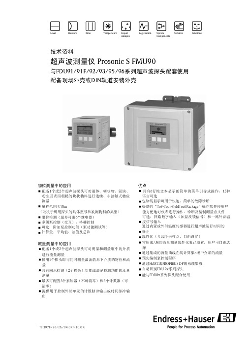
FMU90资料中文说明书
6
Endress + Hauser
Pro nson ic S FMU90
传感器输入
外部限位开关(可选) 外部温度传感器
输入
根据所采用变送器的具体型号,可在FDU91,FDU91F,FDU92,FDU93,FDU95和FDU96中选择 1个或2个探头与其配合使用。Prosonic S变送器能自动识别探头的具体型号。
TI 396F:适用于FDU91/91F/92/93/95/96系列探头 TI 189F:适用于FDU80/80F/81/81F/82/83/84/85/86系列探头
超声波探头内集成了一体化温度探头,以补偿由于超声波运行时间变化而导致的温度变化。 Prosonic S FMU 90可带一路外部温度传感器输入, (FMU90-********B ) *** ,可选以下传感器:
DC电压:35 VDC,100W AC电压:4A,250V,100VA(cosj=0.7)
可选:
保持(末次值) 励磁 去磁 预设值
断电反应 LED灯管2)
延时开启选择 前面板上的黄色LED灯指示相应继电器的工作状态,工作时闪烁。 报警继电器LED指示灯在正常工作时亮。 脉冲继电器LED灯在接收脉冲时闪烁。
用法(举例) 泵反馈信号(FMU 90-*3******B***及FMU 90-*4******B***) 泵费用控制(FMU 90-*3******B***及FMU 90-*4******B***) 计数器的开启/停止/复位(用于流量测量) (FMU 90-*2******B***及FMU 90-*4******B***) min/ max物 位检 测, 如L iquipha nt
D=c·t/2
通过计算出的D值大小,可计算出理想状况下,下列测量变量的数值: 物位L 体积V 通过测量堰或明渠的介质流量Q
日本岛电SR90系列温度调节器中文操作说明

日本岛电SR90系列温度调节器中文操作说明SR90系列温度调节器是一种广泛应用于工业和家庭的温度控制设备,可以精确地调节和控制温度。
本文将详细介绍SR90系列温度调节器的中文操作说明。
1.开箱检查2.连接电源将电源线插入SR90温度调节器的电源插槽。
然后将电源线的另一端插入电源插座,确保电源稳定。
启动电源后,屏幕会亮起。
3.设置温度单位启动SR90温度调节器后,首先需要设置温度单位。
按下菜单按钮进入菜单界面,然后使用方向键选择“温度单位”选项,并按下确认键。
选择所需的温度单位(如摄氏度或华氏度),再次按下确认键保存设置。
4.设置目标温度在菜单界面中,使用方向键选择“目标温度”选项,并按下确认键。
使用方向键增加或减少目标温度值,再次按下确认键保存设置。
5.设置温度控制模式在菜单界面中,使用方向键选择“温度控制模式”选项,并按下确认键。
选择所需的温度控制模式,如PID控制或ON/OFF控制。
6.设置温度调节器根据实际需求,可在菜单界面中设置其他参数,如报警温度范围、时间延迟等。
这些参数对于不同的应用场景可能有所不同,根据需要进行设置。
7.连接温度传感器将温度传感器插入SR90温度调节器的传感器插槽,并确保连接牢固。
传感器应正确安装在需要测量温度的位置。
8.测试运行完成以上设置后,按下系统调试键,温度调节器将开始运行。
在屏幕上可以看到当前温度、目标温度和调节模式等信息。
根据需要进行调整。
9.报警功能SR90温度调节器具有报警功能,在温度超出设定范围时会自动发出警报。
如果出现报警信息,请根据说明书进行相应操作。
10.关闭电源使用完毕后,请将电源线从电源插座中拔出,以确保安全。
维萨拉Veriteq温度数据记录器 1000 1400系列说明书

特点/优势▪行业领先的精度和准确度–0.15 °C ▪低温环境的理想选择–低至-25 °C ▪全天候印制报表▪电池可使用寿命长达10年▪可用同一型号进行验证和连续监测▪两年有限质保▪图表记录仪和硬连线系统的理想替代产品▪可追溯至NIST,A2LA认证校准▪全工作温度范围内的时基校准▪基于可调时间的记录▪咬合式记录仪底座方便网络连接▪三种可选探头提供高精度测量–从-90 °C至+70 °C 1000/1400系列温度数据记录仪包括用于受控环境的VL系列和用于非FDA/GxP行业的SP系列。
VL系列数据记录仪配合vLogVL软件一起,通过提供符合21CFR Part 11 规范要求的防篡改文件和加密电子记录,可以为FDA/GxP受控环境下的应用提供卓越、精度高的解决方案。
SP系列提供紧凑、易部署、测量精度高的记录装置供非FDA/GxP受控环境行业之用。
利用vLogSP软件下载、显示、分析和报告记录的环境数据,SP系列设计用于非FDA/GxP受控环境。
可选的基于浏览器的viewLinc软件为VL和SP系列数据记录仪提供24/7全天候多级报警通知和远程监测。
维萨拉Veriteq温度数据记录器 1000/1400系列应用监测和验证的理想选择:▪冰箱和冷冻箱(低至-90 °C)▪培养箱▪稳定性试验箱▪仓库▪环境条件VL-1400-44x记录跨度:1400-44x启动信道数采样间隔12 3410秒9.8天 4.9天 3.2天 2.4天1分钟 1.9个月29.6天19.7天14.8天5分钟9.8个月 4.9个月 3.2个月 2.4个月15分钟 2.4年 1.2年9.8个月7.4个月1小时9.7年4.8年3.2年2.4年记录跨度:1000-2xx启动信道数采样间隔1210秒 5.5天 2.7天1分钟 1.1个月16.7天5分钟 5.5个月 2.7个月15分钟 1.3年8.3个月1小时5.4年2.7年内部温度传感器系列传感器类型1000-21x高精度密封环氧NTC热电阻存储器数据采样容量1000-2XX 1400-44X48,100 12位 样本85,300 12位 样本存储器类型非易失性EEPROM存储器存储模式用户可选。
GF90

热式质量流量计 2
热式质量流量计
GF90 端子接线图
3
热式质量流量计
GF90 系列流量计型号说明
型号
GF90 插入式 认证标准
0 A B C * 铭牌
A B W * 标准温度和压力
GF92 在线式
0 A B C *
0 1 W *
不需要 FM 认证 CSA ATEX(EEx d IIC T4), CE 认证 其它
7.25” [184mm] 12” [305mm] 系统认证,用户定义
不需要 150 lb.,1½” 凸面法兰 300 lb.,1½” 凸面法兰 150 lb.,2” 凸面法兰 300 lb.,2” 凸面法兰 用户提供 系统认证,用户定义 其它
插入长度单位必须为英寸,精确到小数点后 1 位,其范围为:2.6”~120” max 如:插入长度为 6" 时,填入:0060;插入长度为 18.5" 时,填入:0185
2
B
25 ft. (7.5m)
3
C
50 ft. (15m)
W
W
系统认证,用户定义(导线电阻必须小于 8Ω)
6
4-20 mA,600Ω 最大负载 0-10 VDC,5000Ω 最小负载 0-5 VDC,2500Ω 最小负载 1-5 VDC,2500Ω 最小负载
数字信号:RS-232C 串行端口,可选 HART 或 Profibus 通讯。
开关点(双报警点):开关点可以通过对 GF90 或 GF92 编 程进行现场设定,可设置为高、低或上下限流量报警或者 高、低或上下限过程温度报警。继电器: 10A@115VAC/24VDC, 2A@230VAC。
电气封装: 标准封装为玻璃纤维 NEMA/CSA 4X。危险环境(Class I 和 II,Division 1 和 2,Group B,C,D,E,F 和 G;以 及 EEx d IIC)中采用铸铝和不锈钢封装,可以抗气候和腐 蚀的影响(NEMA/CSA 4X 和相当于 IP66)。 电气连接:1” FNPT。 系统认证:FM,CSA,CE Mark,ATEX(EExdIICT4), CPA。
温度仪表sr93说明书
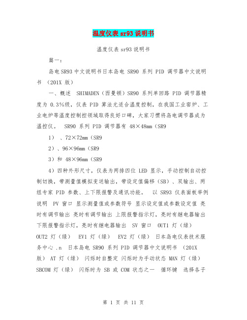
温度仪表sr93说明书温度仪表sr93说明书篇一:岛电SR93中文说明书日本岛电 SR90 系列 PID 调节器中文说明书(201X 版)一、概述 SHIMADEN(西曼顿)SR90 系列单回路 PID 调节器精度为 0.3%级,仪表 PID 算法尤适合温度控制,在我国工业窑炉、工业电炉等温度控制控领域取得良好口碑,大家习惯将岛电调节器成为温控仪。
SR90 系列 PID 调节器有48×48mm(SR91)、72×72mm(SR92)、96×96mm(SR93)和48×96mm(SR94)四种外形尺寸,仪表为两排四位 LED 显示,手动控制自动控制切换,带测量值模拟变送输出,带设定值偏移(SB)、双输出、两组专家 PID 参数、上下限报警及通讯功能。
以 SR93 仪表面板举例说明 PV 窗口显示测量值或参数符号显示设定值或参数设定值亮时有调节输出亮时有调节输出上限报警指示灯,亮时有继电器输出下限报警指示灯,亮时有继电器输出 SV 窗口 OUT1 灯(绿)OUT2 灯(绿) EV1 灯(绿) EV2 灯(绿)日本岛电仪表技术服务中心 .n 日本岛电 SR90 系列 PID 调节器中文说明书(201X 版) AT 灯(绿)闪烁时自整定闪烁时为手动状态 MAN 灯(绿)SBCOM 灯(绿)闪烁时为 SB 或 COM 状态之一循环键选择各子窗口和 0、1 窗口群之间的切换增加键增加数字或修改字符参数减少键增加数字或修改字符参数确认键数字或参数修改后的确认二、SR90 系列 PID 调节器参数设置及代码 SR90 系列 PID 调节器所有参数窗口可分为两个窗口群(0-×窗口群和 1-×窗口群)共60 个选件窗口,每个窗口可设置一个参数。
每个窗口采用了编号,例如传感器量程选择窗口,表示 1 号窗口群的第 48 号窗口。
按增减键修改参数时,面板 SV 窗口的小数点闪动,按“ENT”键确认修改后,小数点灭。
ZC-90系列高绝缘电阻测量仪
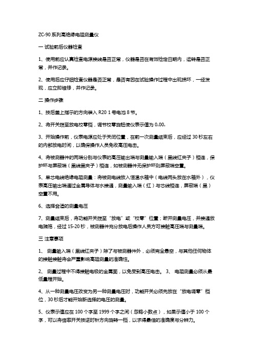
ZC-90系列高绝缘电阻测量仪一试验前后仪器检查1、使用前应认真检查电源接线是否正常,仪器是否在有效检定日期内,运转是否正常,并作记录。
2、使用后应仔细检查仪器是否正常,是否有因在试验操作过程中出现损坏,一经发现,应立即维修,并作记录。
二操作步骤1、按后盖上指示的方向装入R20 1号电池8节。
2、将开关拨至放电校零档,调节校零旋钮使仪表示值为0.00.3、开始操作前,仪表电源应处于关闭位置,在前一次测量结束后,应经过30秒左右的内部放电时间,以确保操作人员免收高压电击。
4、将被测器件的两端分别与仪表的高压输出端与测量输入端(黑线红夹子)相连,保护环与屏蔽端(黑线黑夹子)相连,如被测器件无保护环则屏蔽端空置。
5、单芯电线绝缘电阻测量:将被测电线放入恒温水箱中(电线两头放在水箱外),仪表高压输出端通过金属导体与水接通,测量输入端(红)与芯线相连,屏蔽端(黑)空置不用。
6、选择合适的测量电压7、测量结束后,将功能开关拨至“放电”或“校零”位置;断开测量电压,并接通放电贿赂,经过15-20秒,被测器件充分放电后操作人员方可接触高压端与测量端。
三注意事项1、测量输入端(黑线红夹子)除了与被测器件外,必须完全悬空,与其他任何物体的接触接触将会严重影响高阻测量的准确性。
2、测量过程中不得接触电极的金属面,以免受到高压电击。
3、电阻测量必须从最低量程开始。
4、从一种测量电压改变为另一种测量电压时,功能开关必须先放在“放电调零”档位,30秒后才能开始新选择的电压的测量。
5、仪表示值应在100个字至1999个字之间(忽略小数点),如果示值小于100个字,可以将倍率开关按逆时针方向旋转一档,以求得最佳的准确度与分辨力。
6、出现“:”或“×”符号时,仪表读数无效,零位可能暂时偏移,通常放置一段时间可以恢复。
四、日常维护1、将功能开关拨至电池档,输出电压拨至500V,打开电源开关此时电源指示灯亮,仪表显示数值为电池的电压值,吃电压应在8.5-12.5V照顾之间,如低于8.5V,显示屏上会出现“LOBAT”字样表示电池用完,必须充电或更新一、工作原理ZC-90系列高绝缘电阻测量仪(原名ZC-90系列绝缘电阻测试仪),是便携式数字显示高阻测量仪表,该仪表全面符合国家标准BG/T3048.5 电线电缆以及其他电工制品绝缘电阻的理想设备。
OM-90系列温湿度数据记录器产品介绍说明书

OM-92OM-91Portable Temperature and Humidity Data LoggersOM-90 SeriesU M odels for Temperature (OM-91) and Temperature/Humidity (OM-92)U I mmediate, Delayed (Specific Date/Time) or Pushbutton Start U R eal-Time Mode U U ser-Configurable High and Low Alarms U L ED Status Indicators U U SB Interface for Fast Data Transfer U C ompact, Light Weight, Easy-to-Use U L ong Battery Life The OM-90 Series are portable, battery operated, temperature (OM-91) and temperature/humidity(OM-92) data loggers. The OM-90 Series data loggers offer accurate and repeatable logging for temperature and relative humidity. Temperature is measured to an accuracy of ±0.3°C over the range of 5 to 60°C (41 to 140°F) and ±2.0°C over the full range of -30 to 80°C (-22 to 176°F). Relative humidity is measured to an accuracy of ±3.0% RH over the 20 to 80% RH range and ±5.0% RH over the0 to 100% RH range. Both temperature and relative humidity are logged at a user configurable logging rate which is software selectable.These data loggers are ideal for transportationapplications where it is necessary to document that the material in-transit has stayed within particular environmental limits. High/low alarm limits can be set above or below which LED indicators will be activated so that the user can become aware that the desired transportation conditions have been exceeded.Each data logger can be assigned a 16 character name. This can be helpful in applications where multiple data loggers are used and there is a need to distinguish between them (for example based on location).The data logger includes a very easy to use software application. The application is used for configuration of the logger, extraction of logger data, graphically viewing data, spread sheet analysis of data and saving data to file (typically in comma separated value CSV file format) for third party applications such as Microsoft Excel. The graphical user interface is completely intuitive in terms of configuring new devices andextracting data from a field device. When the user has multiple devices requiring the same setup then a logger setup from a saved configuration file can be preloadedinto the application to help expedite the process and ensure all loggers get setup identically. The application does not require any driver installations to connect to the data logger. Just install the software, run it and then connect the data logger.OM-91temperature data logger.OM-92temperature/humidity data logger.Windows ® software used for data logger configuration and data display in graphical or tabular format.SPECIFICATIONSTemperatureRange: -30 to 80°C (-22 to 176°F) Resolution: 0.01°CAccuracy: ±0.3°C from 5 to 60°C (41 to 140°F) Calibration Accuracy @ 25°C ±20°C: ±0.1°COrdering Example: OM-92-NIST, temperature/humidity data logger with single point NIST calibration certificate.Humidity (OM-92 Only) Range: 0 to 100% RH Resolution: 0.01% RHA ccuracy: ±3% over 20 to 80% RH range; ±5% RH below 20% RH or above 80% RHC alibration Accuracy @ 25% RH: ±1.8% RH @ 25% RH MemoryOM-91: 65,520 temperature measurements O M-92: 65,520 temperature and 65,520 humidity measurementsStart Modes: Immediate start on disconnect from PC, delayed start (scheduled date/time) or pushbutton start Recording Mode: Stop on memory full; when datalogger operation is start/stopped by user intervention via button press, last memory location is retainedRecording Interval: 1 sec, 10 sec, 30 sec, 1 min, 10 min, 30 min, 1 hr (software selectable)Software Compatibility:Windows XP/Vista/7 and 8 (32-bit and 64-bit)Real Time Logging: Displays real time data when connected to a PCReal Time Clock: Time automatically synced to PC Battery Backup: Continues to keep time when off Accuracy: 0.50 sec/day (~3 min/year)Alarms: High and Low alarms for temperature and humidity; dedicated alarm LED indicator LED Indicators: Alarm and status LEDsDevice ID: Each data logger can have a 16 character name assignedConnections: 0.9 m (3') USB Micro-B to PC cable (included)Power: 3V lithium CR2450 battery included (user replaceable)Battery Life: Over 4 year battery life while logging Bypass Mode: Unit is powered from USB when connected to conserve the batteryDimensions: 53 H x 33 W x 15 mm D (1.38 x 2.36 x 0.6")Weight: 25 g (0.9 oz)OM-92OM-91。
G&L SIY 90流量开关

LED功能及设定(模拟量型)
模拟量输出型流量传感器,输出 为4…20mA,正比于流速,输出为
非线性。每个传感器有两个旋 纽,一个为"上限(20mA)"一个为"
下限(4mA)",用于输出设定.
红色LED亮: 流量小于最 低限。 输出<4mA
绿色LED亮: 表明流量处 于设定范围 内。 4mA<输出 <20mA
△接线方式:
M12接插件/直接附2米线可选 2)
△材质:
探头: 不锈钢
外壳: PBT
△重量:
0.4kg
注: 1)模拟量输出型只有直流供电
2)模拟量输出型只有M12接插件, 交流供电型只有直接附线
G1/4连接螺纹
G1/2连接螺纹
开关量输出型
模拟量输出型
G&L-Electronic Germany co., Ltd.
E-mail:dgglsh021@
流量
LED功能及设定(开关量型)
红色LED亮: 断流或流速 低于设定值 开关释放 或模拟量处 于4mA
黄色LED亮: 流速等于设 定值开关动 作
电子式流量开关(传感器) SIY 90 标准系列
黄色及绿色 LED亮: 流速大于设 定值,绿灯 变亮越多表 明流速越大
最大80mA
△流量指示:
LED排 (6个)
△设定方式:
电位计设定
△耐压范围:
100bar
△温度梯度:
4℃/s
△响应时间:
1--13s,典型值2s
△初始化时间:
8s
△电气保护:
反相,短路,过载保护
△防护等级:
IP67
△介质温度:
E+H FMU90中文说明书
TI 396F:适用于FDU91/91F/92/93/95/96系列探头 TI 189F:适用于FDU80/80F/81/81F/82/83/84/85/86系列探头
超声波探头内集成了一体化温度探头,以补偿由于超声波运行时间变化而导致的温度变化。 Prosonic S FMU 90可带一路外部温度传感器输入, (FMU90-********B ) *** ,可选以下传感器:
1)适用于带流量测量软件的仪表型号(FMU 90-*2**********)。 2)适用于带显示操作单元的仪表型号。
8
Endress + Hauser
Pro nson ic S FMU90
PROFIBUS DP 接口
供电电压 / 功率消耗 / 电流消耗 电气隔离 保险丝
Endress + HSA认证 的F DU83、FDU84、FDU 85及 FD U86探头与 FM U90变送器相配合 使用时,系统不一定满足上述防爆认证要求。
Prosoinc S FMU90带四路输入用于输入外部限位开关信号(FMUFMU 90-********B***)
开关量可选: 外部无源限位开关(N C/NO开关) 0:<8V;1:>16V
Endress + Hauser
3
物位测量的应用实例
鹦鹉90系列理化指标
鹦鹉90系列理化指标
【实用版】
目录
1.鹦鹉 90 系列简介
2.理化指标概述
3.鹦鹉 90 系列理化指标具体内容
4.总结
正文
【1.鹦鹉 90 系列简介】
鹦鹉 90 系列,是我国某知名品牌推出的一款高性能智能家居设备。
该系列产品凭借着其优秀的性能和便捷的操作,受到了广大消费者的喜爱。
【2.理化指标概述】
理化指标,是指对物质的物理和化学性质进行检测和测量的参数。
对于鹦鹉 90 系列这样的智能家居设备,其理化指标主要包括尺寸、重量、材质、工作温度、工作湿度等。
【3.鹦鹉 90 系列理化指标具体内容】
鹦鹉 90 系列的理化指标如下:
- 尺寸:长 x 宽 x 高(mm):200x100x300
- 重量:约 5kg
- 材质:abs 工程塑料
- 工作温度:-10℃至 45℃
- 工作湿度:10% 至 90%
这些理化指标体现了鹦鹉 90 系列的尺寸适中,便于携带和安装;重
量适中,保证设备稳定性的同时,也便于搬运和移动;材质选用 abs 工程塑料,具有良好的耐热性和耐腐蚀性;工作温度和工作湿度范围宽广,适应各种环境。
- 1、下载文档前请自行甄别文档内容的完整性,平台不提供额外的编辑、内容补充、找答案等附加服务。
- 2、"仅部分预览"的文档,不可在线预览部分如存在完整性等问题,可反馈申请退款(可完整预览的文档不适用该条件!)。
- 3、如文档侵犯您的权益,请联系客服反馈,我们会尽快为您处理(人工客服工作时间:9:00-18:30)。
拧入式热电阻,配有插拔式连接器
TB 90.2004
传感器插件
装配 测量 电路 传感元件
抗震型标准化传感器插件 单支 >2线制, 4线制 双支 > 2线制
Pt 100, Pt 500, Pt 1000 B级 (标准) , A级
拧入式热电阻,配有插拔式连接器
TB 90.2004
保护管
材质 l 直径 插深 过程连接
TB 90.2810
夹持连接
球形焊台 牛奶管螺纹
焊台
Varivent 连接
Ingold 连接
接线方式
不锈钢接线头
塑料接线头
塑料接线盒
食品工业/制药业用热电阻
TB 90.2810
使用场合/应用行业
食品机械行业 食品制造商 制药业
石化,化工行业用热电阻
TB 90.2810
特点
温度测量范围 -200...+600 °C 多种接线盒可选 (有隔爆型 EEx „d“ ) 过程连接 > 螺纹 > 法兰 > 焊接 保护管材质:不锈钢、钛、钽、哈氏合金 因康镍合金. 保护管涂层: 取聚四氟乙烯, halar 传感器插件可换 单/双支 一体化温度变送器可选 (有本安型 EEx „i“ ) 可提供测试证书
TB 90.2305
特点
温度测量范围-50...+260 °C 多种连接电缆 电缆保护器 多种样式的手柄 不锈钢保护管, material Nr. 1.4571 测量点 > 锥形 > 斜角 两线制或四线制 蒸汽密封和压力 高机械强度
刺入式热电阻 JUMO - 食品温度测量
TB 90.2305
使用场合/应用行业
本安防爆型
EEx ia II C T6 配有本安防爆型变送器 4...20 mA 信号输出 可以用在1区
通用过程热电阻
TB 90.2810
质保证书 3.1 B
质量保证测试包括以下内容
材质测试 压力测试 泄漏测试 精度测试/校验 绝缘电阻测试
通用过程热电阻
TB 90.2810
使用场合/行业
化学工业 化工设备供应商 过程技术工程设计院 石化行业 制药业 炼油厂
90系列温度探头
温度探头 食品工业用热电阻 化学工业用热电阻 插头连接式热电阻(抗震热电阻) 刺入式热电阻(食品行业) 插入式热电阻(测蒸汽) 槽热电阻 烤箱用热电阻(带)
温度传感器 铂电阻—玻璃封装 铂电阻—陶瓷封装 铂电阻—箔片封装 铂电阻—SMD表面安装
食品工业/制药业用热电阻
TB 90.2810
特点
温度测量范围 -50...+250 °C 多种接线盒 可选
保护等级 IP 54...IP 65
过程连接 ( CIP - 应用 )
> 夹持连接
> 牛奶管螺纹安装
> 焊接座
>焊接座
> Varivent-连接
> Ingold-连接
不锈钢保护管
单/双支 (A级传感器) 一体化温度变送器
食品工业/制药业用热电阻
刺入式热电阻
TB 90.2305
刺入式热电阻
TB 90.2305
主要应用
烹饪和熏制设备
精加工设备和烤箱
刺入式热电阻
TB 90.2305
市场要求
食品应用 - 必须为中性材质 高机械强度 高抗震性 温度 - 抗冲击性(骤冷骤热) 蒸汽-密封性 压力 -耐压性 供货的迅速性
刺入式热电阻 JUMO - FOOD温度测量
工作温度
不锈钢
Mat. Ref. 1.4571 8 mm 50, 100, 150, 250 mm… (以50mm为单位增加) G 1/4 , G 3/8 , G 1/2 管螺纹 M 18x1,5 , M 20x1,5 1/2 - 14 NPT -50...+200 C°
拧入式热电阻,配有插拔式连接器
汽车、卡车、压缩行业用热电阻
用于震动性环境以及测量 要求非常严格的场合 电连接:卡锁连接 直形或角形连接器
汽车、卡车、压缩行业用热电阻
• 用于震动性环境以及测量 要求非常严格的场合 带配套电缆的温度探头
拧入式热电阻,配有插拔式连接器
TB 90.2004
使用场合/应用行业
挤压机 齿轮和变速箱制造造 制冷系统,制冷单元 机器制造商, 有轨车辆制造商 机动车辆制造商
TB 90.2004
应用
Germanischer Lloyd 劳埃德船级社认证 使用在封闭性环境 与产热产品配用 高抗震性能
4 g , 5 - 200 Hz 可安装在内燃机或挤压机上
可提供其它认证
拧入式热电阻,配有插拔式连接器
TB 90.2004
使用场合/应用行业
柴油发动机 海军柴油发动机 GL 变速箱 紧急备用电机 区域供热站 制冷系统,制冷设备
石化,化工行业用热电阻
TB 90.2810
过程连接
螺纹 G 1/2 ; 1 pipe NPT
法兰 C DN 25 PN 40 C DN 40 PN 40
保护套 D1 / D2 D4 / D5
石化,化工行业用热电阻
TB 90.2810
隔爆型
EEx d II C T6 可以用在1区
通用过程热电阻
TB 90.2810
肉类加工设备制造商 公共食堂设备供应商 屠宰场 制药业
微型刺入式热电阻
TB 90.2305
微型刺入式热电阻
TB 90.2305
食品加工和精制业核心温度测量 温度测量范围 -100...+200 °C 保护管 不锈钢, 插深 30...80 mm 传感器插件 Pt 100 B级两线制或三线制 电连接 硅胶或聚四氟乙烯电缆 蒸汽密封和压力密封 保护等级 IP 67 高机械强度 抗温度冲击性
汽车、卡车、压缩行业用热电阻
应用
拧入式热电阻,配有插拔式连接器
TB 90.2004
拧入式热电阻,配有插拔式连接器
TB 90.2004
装配图
插拔连接器 传感器插件
保护管
拧入式热电阻,配有插拔式连接器
TB 90.2004
插拔式连接器
材质 保护等级 连 9 , PG 11 125 C°
拧入式热电阻,配有插拔式连接器
TB 90.2004
特点
温度测量范围 -50...+300 °C 安全可靠的插拔式连接端子 保护等级 IP 65 过程连接 > 螺纹 保护管材质多种多样 高抗震性抗冲击性 配件 与之配套的连接器和硅胶电缆
汽车、卡车、压缩行业用热电阻
用于震动性环境,以及测量 要求十分严格的场合 温度测量范围 -50...+300 °C 过程连接: 英制、公制或 NPT螺纹 保护管材质 黄铜,不锈钢,特种涂层 传感元件t Pt 100, 500, 1000 Cl.B, NTC, KTY 插拔式连接器 高抗震性 保护等级 IP 65, IP 69k
