电磁锁安装指南说明书
M420、M450、M490和M400系列单电磁锁安装指南说明书

Features
Automatic Voltage Selection (AVS) Magnet immediately detects 12VDC or 24VDC when power is connected.
Anti-Tamper Switch (ATS) An indication is provided should the magnet cover become unsecured from lock.
LHR
OR RHR
2 Install MBS indicator (optional, plus models ONLY).
2a Remove cover.
3 Install ATS (optional, plus models ONLY)
3a Remove end block and wiring cover.
ON
Cautions indicate potentially hazardous conditions, which if not avoided or corrected, may cause minor or moderate injury.
Cautions may also warn against unsafe practices.
Trims
Basic Auto Voltage Selection (AVS) for 12 or 24VDC
Plus Basic features + Door Position Switch (DPS), Magnetic Bond
Warnings and Cautions
WARNING
Warnings indicate potentially hazardous conditions, which if not avoided or corrected, may cause death or serious injury.
电磁锁安装方法 很清楚!

电磁锁(磁力锁)的标准安装方法一.外开门的表面安装方法:(参照图一至图八)第一步:首先用螺丝刀打开盖板,再用六角扳手打边板,准备安装(见图一)第二步:拿出安装纸板,将纸板沿着虚线折叠按图二所示方法把纸板放到所需装锁的位置,然后把需要打孔的地方做上记号后打孔.第三步:A.继铁板的固定(参见图三)将内六角螺丝插入继铁板中,把橡胶华司置与两片金属华司之间,然后套在内六角螺丝上。
将继铁板插入门上打的三个孔中,同时把香菇头从门的另一面插入,利用六角扳手将继铁板锁在门上。
B.边板的固定(参见图三)把边板用两个半圆头螺丝固定在先前打孔的门框上(固定在边板的长形孔中)。
注意:不要将边板锁紧,让其能前后能移动以利于安位置的修正。
C.修正边板的位置使边板与继铁板的位置合适,目的使锁主体能与继铁板紧密的接触。
D:固定锁主体与边板锁紧边板的半圆头螺丝后,再锁上所有的沉头螺丝,然后再卸下半圆头螺丝,在适当的位置钻孔以便接线。
最后用六角扳手把锁主体锁在边板上。
(参见图四)第四步:按照说明书的指示接线。
第五步:盖上盖板,把小铝柱体塞进锁主体参见图五的螺丝孔中。
参见图六图七与图八所示为典型的外开门外置式的安装式样★安装注意事项在安装继铁板的时候,不要把它锁紧,让其能轻微摇摆以利于和锁主体自然的结合。
二、内开门的表面安装(ZL型支架的安装方法):解决外装磁力锁的内装问题。
内开门做表面安装时需要有辅助配件来协助安装,我们选用富有装饰性的优质进口铝材来制做这种安装配件:Z&L支架。
每套Z&L支架含三块铝材配件,其中较长的一块L1是配给锁主体使用;另外两块较短的Z2、Z3配给继铁板用。
Z2是安装在门上的,边上有五个沉孔,是用于固定在门上;Z3是用于固定继铁板的,边上有三个孔,中心孔应与继铁板的中心孔对齐.下面介绍安装方法。
a. 先将Z&L支架中的L1支架放在装锁的位置上,用M5*25的自攻螺丝固定于门框或墙面上。
箱变专用电磁门锁说明书

DSN型电磁门锁安装使用说明书
1,产品用途和使用范围
本产品是一种防止高压开关设备电气误操作的电控机构联锁装置,主要供高低压开关柜、箱式变柜门以及其他需要安全联锁的地方实现强制联锁,防止误入带电间隔和防误操作的发生,是发电和供电部门不可缺少的闭锁装置。
2,产品原理
本产品是应市场需求,推出的与本公司前几种产品不一样的电磁锁。
电磁锁内自带闭锁装置,无需跟高压带电显示闭锁装置连接,直接从变压器低压侧或者PT 低压侧取电(220V、110V),当电磁锁不通电时,按下按钮转动把手即可打开柜门。
当电磁锁通电时,任何方法均无法打开(除非把锁破坏性拆除)。
紧急情况下,可以用随机附带的紧急解锁钥匙打开柜门。
(解锁钥匙必须专人保管)3,工作条件
周围空气温度:上限:+40℃,下限:一般地区-10℃,高寒地区-25℃。
海拔高度:安装地区海拔不高于1000m。
环境湿度:空气相对湿度日平均不大于95%、月平均值不大于90%。
环境条件:无明显污秽、无易燃、易爆、化学腐蚀和盐雾及无经常性剧烈振动场所。
开孔图:。
电磁锁安装指南说明书

电磁锁安装使用说明书(双孔)
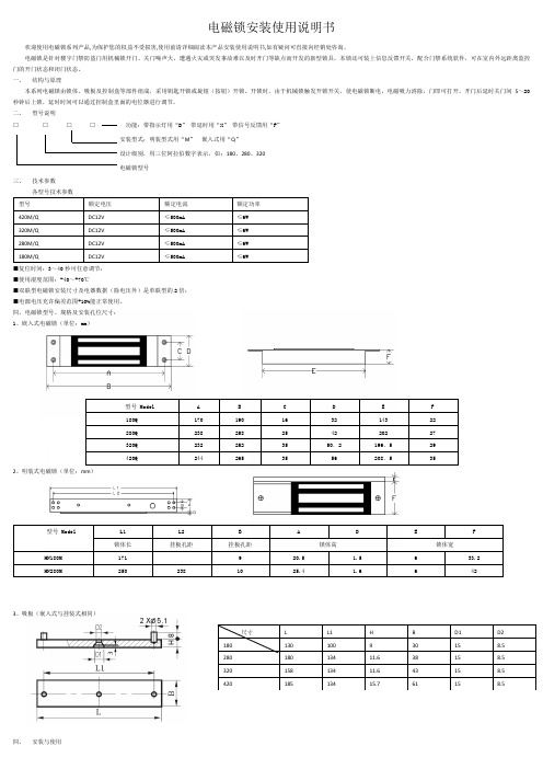
电磁锁安装使用说明书欢迎使用电磁锁系列产品,为保护您的权益不受损害,使用前请详细阅读本产品安装使用说明书,如有疑问可直接向经销处咨询。
电磁锁是针对楼宇门禁防盗门用机械锁开门、关门噪声大,遭遇火灾或突发事故难以及时开门等缺点而开发的新型锁具。
本锁还可装上信息反馈开关,配合门禁系统软件,可在室内外远距离监控门的开门状态和闭门状态。
一、结构与原理本系列电磁锁由锁体、吸板及控制盒等部件组成,采用钥匙开锁或旋钮(按钮)开锁。
开锁时,由于机械锁触发开锁开关,使电磁锁断电,电磁吸力消除,门即可打开。
开门后延时关门间5~20秒钟后上锁,延时时间可以通过控制盒里面的电位器进行调节。
二、型号说明□□□□功能:带指示灯用“D”带延时用“X”带信号反馈用“F”安装型式:明装型式用“M”嵌入式用“Q”设计级别,用三位阿拉伯数字表示,如:180、280、320电磁锁型号三、技术参数型号额定电压额定电流额定功率420M/Q DC12V ≤500mA≤6W320M/Q DC12V ≤500mA≤6W280M/Q DC12V ≤500mA ≤6W180M/Q DC12V ≤500mA ≤6W■复位时间:3~40秒可任意调节;■使用湿度范围:-40~+70℃■双联型电磁锁安装尺寸及电器数据(除电压外)是单联型的2倍;■电源电压充许偏差范围+10%能正常使用。
四、电磁锁型号、规格及安装孔位尺寸:1、嵌入式电磁锁(单位:mm)型号 Model A B C D E F180Q 170 190 16 32 143 22280Q 238 258 25 42 202 27320Q 232 252 35 50.2 196.5 29420Q 244 265 35 56 208.5 352、明装式电磁锁(单位:mm)型号 Model L1 L2 B A D E F锁体长挂板孔距挂板孔距锁体高锁体宽HN180M 171 9 20.5 1.5 6 33.2HN280M 250 238 10 25.4 1.6 6 423、吸板(嵌入式与挂装式相同)尺寸L L1 H B D1 D2180 130 100 9 30 15 8.5280 180 134 11.6 38 15 8.5320 158 134 11.6 43 15 8.5420 185 134 15.7 61 15 8.5四、安装与使用1、控制盒的安装①安装方法:控制盒装在门的房间内侧面,锁头朝门外。
电磁锁安装图文
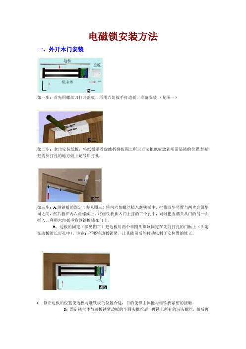
电磁锁安装方法一、外开木门安装第一步:首先用螺丝刀打开盖板,再用六角扳手打边板,准备安装(见图一)第二步:拿出安装纸板,将纸板沿着虚线折叠按图二所示方法把纸板放到所需装锁的位置,然后把需要打孔的地方做上记号后打孔.第三步:A.继铁板的固定(参见图三)将内六角螺丝插入继铁板中,把橡胶华司置与两片金属华司之间,然后套在内六角螺丝上。
将继铁板插入门上打的三个孔中,同时把香菇头从门的另一面插入,利用六角扳手将继铁板锁在门上。
B.边板的固定(参见图三)把边板用两个半圆头螺丝固定在先前打孔的门框上(固定在边板的长形孔中)。
注意:不要将边板锁紧,让其能前后能移动以利于安位置的修正。
C.修正边板的位置使边板与继铁板的位置合适,目的使锁主体能与继铁板紧密的接触。
D:固定锁主体与边板锁紧边板的半圆头螺丝后,再锁上所有的沉头螺丝,然后再卸下半圆头螺丝,在适当的位置钻孔以便接线。
最后用六角扳手把锁主体锁在边板上。
(参见图四)第四步:按照说明书的指示接线。
第五步:盖上盖板,把小铝柱体塞进锁主体参见图五的螺丝孔中。
参见图六图七与图八所示为典型的外开门外置式的安装式样。
安装注意事项在安装继铁板的时候,不要把它锁紧,让其能轻微摇摆以利于和锁主体自然的结合。
二、内开门的表面安装内开门做表面安装时需要有辅助配件来协助安装,我们选用富有装饰性的优质进口铝材来制做这种安装配件:Z&L支架。
每套Z&L支架含三块铝材配件,其中较长的一块L1是配给锁主体使用;另外两块较短的Z2、Z3配给继铁板用。
Z2是安装在门上的,边上有五个沉孔,是用于固定在门上;Z3是用于固定继铁板的,边上有三个孔,中心孔应与继铁板的中心孔对齐.下面介绍安装方法。
a. 先将Z&L支架中的L1支架放在装锁的位置上,用M5*25的自攻螺丝固定于门框或墙面上。
b.用六角扳手将锁主体锁在L1支架上。
c. 对应于L1支架的位置把Z2支架固定在门上。
d. 将继铁板插入Z1的三个孔中假固定,然后门关好,使磁铁和继铁板紧密吻合,确定Z1、Z2 的衔接位置。
镇江市电工器材厂 DSN3型系列户内电磁锁 说明书

w w w.dg q cc.c om051182976667w ww.dg q cc.co mw w w.dg q cc.c om051182976667w ww.dg q cc.co mw w w.dg q cc.c om051182976667w ww.dg q cc.co m DSN3型系列户内电磁锁安装使用说明书镇江市电工器材厂w w w .d g q c c .c o m 0511********ww w .d g q c c .c o m w667ww w c c .co m w w w .d g q c c .c o m 0511********ww w .d g q c c .c o m 1.概述1.1产品主要用途和适用范围DSN 口型户内电磁锁为户内防止电气误操作的闭锁装置,适用于户内固定式高压开关柜、手车柜的隔离开关和接地装置等高压开关设备的操动机构和柜门的闭锁装置,特别适用于WBF-III 型微机,闭锁装置,防止电气误操作事故的发生。
1.2使用环境条件:a.环境温度:上限+40℃,下限-lO ℃,高寒地区-25℃;b.海拔高度不超过2500m ;c.湿度:相对湿度日平均值不大于95%,月平均值不大于90%;J.使用场所应无火灾爆炸危险,化学腐蚀及经常的剧烈震动;e.特殊环境由用户和制造厂协商解决。
1.3产品型号和名称1.4主要技术参数和规格2.结构和工作原理2.1结构:DSN 口型系列电磁锁分柜门电磁锁、刀闸电磁锁、接地电磁锁三种,由机械和电气两部分组成。
机械部分包括锁(壳)体、盖板、锁栓、解锁钥匙等,电气部分包括指示灯、电磁铁、行程开关、辅助开关、接线插座等。
2.2工作原理:采用间吸式原理,电磁锁在有电压时,指示灯亮,按下行程开关,串联的线圈通电,锁栓释放,电磁锁便可开锁,辅助开关同时得到锁具开或关的状态。
型号名称电压(V)锁栓行程(mm)锁栓直径(mm)DSN□-MZ(MY)柜门电磁锁AC:220DC48、110、220≥1010DSN□-DZ(DY)刀闸电磁锁同上≥109DSN□-J接地电磁锁同上棒插到位/w ww .d g q c c .c o m 0511*******7w ww.d gq c c .co m w w w .d g q c c .c o m 0511********w w w .d g q c c .c o m w w w .d g q c c .c o m 0511********w w w .d g q c c .c o m 特殊情况下,电磁锁无电压时需开锁,可借助解锁钥匙解锁,电磁锁的接线原理见图1。
EMLOCK电磁锁安装说明书
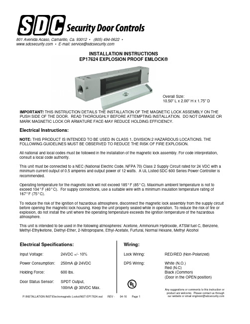
Any suggestions or comments to this instruction or product are welcome. Please contact us through INSTALLATION INSTRUCTIONSEP17624 EXPLOSION PROOF EMLOCK®Electrical Instructions:NOTE: THIS PRODUCT IS INTENDED TO BE USED IN CLASS 1, DIVISION 2 HAZARDOUS LOCATIONS. THE FOLLOWING GUIDELINES MUST BE OBSERVED TO REDUCE THE RISK OF FIRE EXPLOSION.All national and local codes must be followed in the installation of the magnetic lock assembly. For code interpretation, consult a local code authority.This unit must be connected to a NEC (National Electric Code, NFPA 70) Class 2 Supply Circuit rated for 24 VDC with a minimum current output of 0.5 amperes and output power of 12 watts. A UL Listed SDC 600 Series Power Controller is recommended.Operating temperature for the magnetic lock will not exceed 185° F (85° C). Maximum ambient temperature is not to exceed 104° F (40° C). For supply connections, use a suitable wire with a minimum insulation temperature rating of 167° F (75° C).To reduce the risk of the ignition of hazardous atmosphere, disconnect the magnetic lock assembly from the supply circuit before opening the magnetic lock housing. Keep the unit properly sealed while in operation. To reduce the risk of fire or explosion, do not install the unit where the operating temperature exceeds the ignition temperature of the hazardous atmosphere.This unit is intended to be used in the following atmospheres: Acetone, Ammonium Hydroxide, ATSM fuel C, Benzene,Methyl-Ethylketone, Diethyl-Ether, 2-Nitropropane, Ethyl-Acetate, Furfural, Normal Hexane, Methyl AlcoholElectrical Specifications:Input Voltage:24VDC +/- 10%Power Consumption:250mA @ 24VDC Holding Force:600 lbs.Door Status Sensor:SPDT Output,100mA @ 30VDC Max.801 Avenida Acaso, Camarillo, Ca. 93012 • (805) 494-0622 ••E-mail:***********************IMPORTANT! THIS INSTRUCTION DETAILS THE INSTALLATION OF THE MAGNETIC LOCK ASSEMBLY ON THE PUSH SIDE OF THE DOOR. READ THOROUGHLY BEFORE ATTEMPTING INSTALLATION. DO NOT DAMAGE OR MARK MAGNETIC LOCK OR ARMATURE FACE-MAY REDUCE HOLDING EFFICIENCY.Wiring:Lock Wiring:RED/RED (Non-Polarized)DPS Wiring:White (N.O.)Red (N.C)Black (Common)(Door in the OPEN position)Overall Size:10.50" L x 2.00" H x 1.75" DNOTE: A 2-½" (64 mm) reveal is required to assure rigid mounting of the EP17624.See Figure 1 elevation profiles to determine mounting application requirements for each individual application.Figure 1 – Magnetic Lock Mounting To FrameDPS MAGNET*NOTE: NOT TO SCALEFILLERPLATE(END CAP FIELD REVERSIBLE)Figure 1ASTANDARD (PREFERRED) INSTALLATIONREINFORCEMENT BY OTHERSWITH FILLER PLATEFigure 1B AS SHOWNDPS WIRINGWHT – N/O BLK – COM RED – N/CSTEP 4.Insert one (1) spring washer over 5/16"-18 "special" shoulder bolt, insert bolt through armature. Add three (3) conical spring washers and one (1) flat washer over shoulder bolt. See Figure 2 - details for each type of installation. All parts must be assembled properly before installing armature to the door. Install the complete armature assembly on the door per Figure 2 details.STEP 5.Tighten shoulder screw(s) securely with allen wrench. (Do not overtighten.)NOTE: ALL ARMATURES ARE NORMALLY EQUIPPED WITH A PERMANENT MAGNET ON ONE END. BE CERTAIN TOINSTALL ARMATURE SO DPS MAGNET LINES UP WITH THE DOOR POSITION SWITCH INSIDE THE HOUSING OF MAGNETIC LOCK ASSEMBLY.Figure 2 –Armature Mounting To Door(s)REINFORCED DOORWOOD DOORFigure 2CFigure 2B C LC LSTEP 1.Mark door(s) according to armature location template and dimensions on Page 2.STEP 2.Drill and prep holes in door per armature template on Page 2 and door type below:2A. For THRU BOLT mounting in hollow metal door(s) drill 11/32" (9 mm) DIA. hole thru door, enlarge hole in outside face to 1/2" (13 mm) DIA.2B. For THRU BOLT mounting in solid core wood door(s), drill 11/32" (9 mm) DIA. hole thru door(s), enlarge hole in outside face to 1/2" (13 mm) DIA., 1" (25 mm) deep.2C. For REINFORCED DOOR (Minimum 3/8" (10 mm) thickness) drill and tap thru reinforcement for 5/16"-18 screw.STEP 3.Gently tap the (2) 3/16" (5 mm) diameter spring pins into rear side of armature(s).STEP 7.Mark frame per EMLock template and dimensions on Page 2.STEP 6.Remove housing cover of maglock assembly by removing the two (2) phillips screws on the front face of the maglock, and the (2) phillips screws on the back of the housing.STEP 8.Drill two (2) #7 thru holes and tap for 1/4-20 machine screws per the EMLock template. Attach maglock assembly to the frame using either (2) #14 sheet metal screws OR (2) 1/4"-20 machine screws and external tooth lock washers, tighten only enough to hold the unit in place. (If filler plate is used, assure that the screws go through both the filler plate and the door frame.)STEP 9. Run electrical conduit per NFPA 70 into conduit hole with 1/2-14 NPT.STEP 10.Make all electrical connections per applicable wiring instructions. Use wire nuts, crimp connectors or solder to assure good connections.STEP 11.Energize EMLock assembly. Adjust assembly so door is snug against door stop; Tighten two (2)preliminary screws in Step 8 securely.STEP 12.De-energize system. Using mounting plate as template, drill #21 drill and tap for 10-32 screws (minimum two (2) places). Install screws and tighten securely. Re-energize system, recheck alignment of EMLock assembly to armature by opening and closing door(s).STEP 13.Re-install EMLock housing cover.RU LISTEDL24 VOLTS D.C. 0.25 AMP 6.0 WATTS OPERATING TEMPERATURE 85 DEGREE CENTIGRADE MAXIMUM AMBIENT TEMPERATURE 40 DEGREE CENTIGRADE FOR SUPPLY CONNECTIONS USE 75 DEGREE CENTIGRADE WIRE THIS UNIT MAY BE USED IN THE FOLLOWING ATMOSPHERE:ACETON, AMMONIUM HYDROXIDE, ASTM FUEL C, BENZENE,METHLY ETHYL KETONE, DIETHYL EHTER, 2-NITRO-PROPANE,ETHYL ACETATET, FURFURAL, NORMAL HEZANE, METHYL ALCOHOLCAUTION:TO REDUCE THE RISK OF IGNITION OF HAZARDOUS ATMOSPHERES,DISCONNECT THE DOOR HOLDER FROM THE SUPPLY CIRCUIT BEFORE OPENING. KEEP TIGHTLY CLOSED WHEN IN OPERATION.TO REDUCE THE RISK OF FIRE OR EXPLOSION, DO NOT INSTALL WHERE THE MARKED OPERATION TEMPERASTURE EXCEEDS IGNITINO TEMPERATURE OF HAZARDOUS ATMOSPHERES.UNIT MUST BE CONNECTED TO A N.E.C. CLASS 2 SUPPLY CIRCUIT MAGNETIC LOCK: 17XHD SERIES.DOOR HOLDER FOR USE IN HAZARDOUS LOCATIONS Class 1 Div 2ISSUE # U-557。
美国三星公司产品号2600系列安全门电磁锁安装说明书

2599-220
2600-402 2600-410 2600-413 2600-414 2600-439 2600-528 2600-619 2600-731 2600-810 2601-161 2601-162 2601-290 2601-292 2601-293 2601-305 2601-355 2615-154 2615-181 2616-000 2616-002 2616-003 2616-004
6500-105 Box 2620-409 Nut 4X
2616-580 Nut 4X
2600-810 Bushing 1200-028 Outlet
DRAWN Tpham
DATE
11/11/20
DWG. NO.
6550-380
C REV.
NAME Swing Gate Oper 1HP 115V Primary
2616-018 Screw 4X
3130-023 Terminal
3129-002 Cover
2616-003 Screw 4X
2600-414 Terminal
DRAWN Tpham
DATE
11/11/20
DWG. NO.
6550-380
C REV.
NAME Swing Gate Oper 1HP 115V Primary
Bushing 7/8 Poke Thru Flaps Collar 1 1/2" ID
Motor Assy 1HP Model 6550 Belt - 62" BX-62
Pulley 18 3/4" Cast Iron BK190H Hub 1" Dia for Pulley 18 3/4" Gearbox Sw Gate 6550 Spacer Nylon 5/8"L x 3/8"ID Bolt Hex Head 5/16-18x1 Bolt Hex Head 1/2-13 x 1 1/2 Screw Phillips Head 6-32x1/4 Screw Phillips Head 6-32x1/2 Screw Phillips Head 6-32x3/4 Screw Phillips Head 6-32 x 1.0
磁力锁安装说明
安装说明…………………………………………………………………………………………………………本节主要介绍磁力门锁的安装方法。
磁力门锁主要有内置式、外置式两种安装方法。
内置式是指锁被埋嵌在门框里,与门浑然一体,外观上看不出,此种安装方式对门框尺寸有要求;外置式是指锁装在门框外,安装灵活方便,一般不受门类的限制。
我们使用的门以其打开的方式可分为内开式、外开式及双开式、移门;以其制作材料的不同可分为木门、玻璃门、铁门、铝合金门等类。
为适合不同门类的安装,我们提供相应的配件以达到安装方便的目的。
一.外开式门的安装方法1.表面安装(外置式)参照图一至图八1-1 木门、铁门、铝合金门的安装方法。
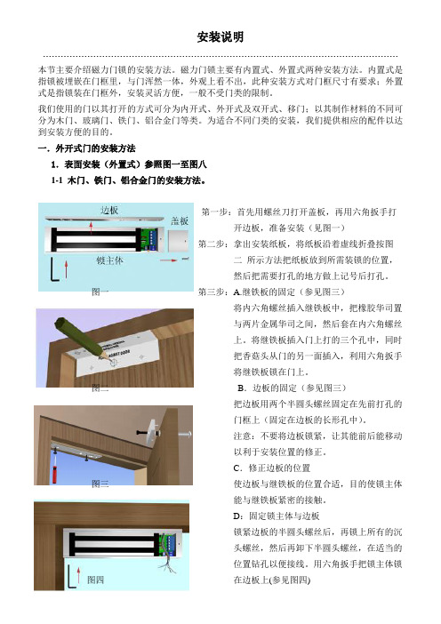
第一步:首先用螺丝刀打开盖板,再用六角扳手打开边板,准备安装(见图一)第二步:拿出安装纸板,将纸板沿着虚线折叠按图二所示方法把纸板放到所需装锁的位置,然后把需要打孔的地方做上记号后打孔。
图一第三步:A.继铁板的固定(参见图三)将内六角螺丝插入继铁板中,把橡胶华司置与两片金属华司之间,然后套在内六角螺丝上。
将继铁板插入门上打的三个孔中,同时把香菇头从门的另一面插入,利用六角扳手将继铁板锁在门上。
图二B.边板的固定(参见图三)把边板用两个半圆头螺丝固定在先前打孔的门框上(固定在边板的长形孔中)。
注意:不要将边板锁紧,让其能前后能移动以利于安装位置的修正。
C.修正边板的位置图三使边板与继铁板的位置合适,目的使锁主体能与继铁板紧密的接触。
D:固定锁主体与边板锁紧边板的半圆头螺丝后,再锁上所有的沉头螺丝,然后再卸下半圆头螺丝,在适当的位置钻孔以便接线。
用六角扳手把锁主体锁图四在边板上(参见图四)图五 图六 第四步:按照说明书的指示接线。
第五步:盖上盖板,把小铝柱体塞进锁主体 参见图五 的螺丝孔中。
参见图六图七 图八图七与图八所示为典型的外开门外置式的安装式样。
★ 安装注意事项在安装继铁板的时候,不要把它锁紧,让其能轻微摇摆以利于和锁主体自然的结合。
多玛卡巴 MUTO 电磁锁 (Elock MEM4400) 安装说明书 接线指南
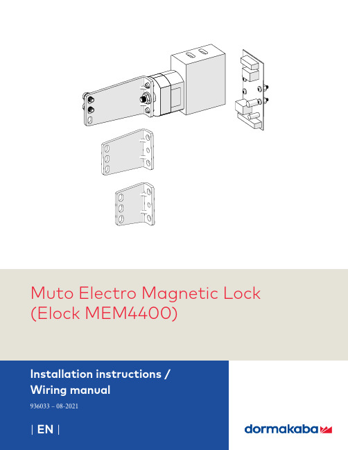
Muto Electro Magnetic Lock (Elock MEM4400)dormakaba MUTO Electro Magnetic LockTable of Contents Installation InstructionsTable of contents1 Technical specifications 31.1 Overview 31.1.1 General information 31.1.2 Intended use 31.1.3 Glass requirements and fittings 31.1.4 Requirements for glass panel 31.1.5 Safety instructions 31.1.6 Symbols used - Safety/Installation 31.1.7 Maintenance, care, repair 31.1.8 Disposal 31.2 Specifications - technical data 41.3 Dimensions 42 Installation instructions 42.1 Overall 42.2 Secure armature bracket to rollers:to glass or wood doors 52.3 Secure terminal block to door frame 62.4 Secure mag lock to wall/door frame structure 63 Change handing of mag lock 73.1 Change handing 74 Wiring the circuit board 84.1 Wiring diagram 81.1 O verviewThese instructions are for installation of MUTOPREMIUM sliding door system XL150 / XL80 / XL120 for the following mounting and style versions:1. Wall or Ceiling mount1.1.1 General information • dormakaba requires use of tempered monolithic ortempered laminated glass.• dormakaba glass hardware is not suitable forapplication in rooms where chemicals (e.g. chlorine) are used as indoor swimming pools, saunas or salt-water pools.• Never move sliding panels faster than walkingspeed and always stop the door manually before it reaches end position.• Do not slide doors with excessive force. Installlimiting stop to prevent door from opening too far.1.1.2 Intended use • For sliding door in dry indoor areas only • For manual slowly opening and closing only1.1.3 Glass requirements and fittings • The substructure/wall must be able to bearpermanent loads and be level (max. tolerance: 1/16” [2] per 39” [1m]).• Fasteners must be sufficiently dimensioned for thesubstructure/wall and weight of the door.• When adjusting glass components, always stick tothe required clearance for the respective hardware. Adjust clearance so glass does not come in contact with any hard surfaces such as glass, metal or concrete.• Do not use excessive force when installing theglass (avoid over tightening screws).1.1.4 Requirements for glass panel • dormakaba requires use of fully tempered glass,which complies with ASTM C 1036 and ASTM C 1048. Secondary heat soaking processes are optional but not required. This applies to both tempered monolithic and tempered laminated glass.• Clamping area must be flat and uncoated (noself-cleaning coating!)• Never use glass with conchoidal fractures and/ordamaged edges.1.1.5 Safety instructions • Installation requires two people.• Only properly qualified and specially trained staffare authorized to mount dormakaba glass hardware.•Due to crushing hazards and possible injury caused by breakage of glass during mounting,corresponding protective clothing (especially gloves and protective goggles) is required.•Work on electrical equipment and 240/120 VAC wiring installation must be performed ONLY by qualified personnel.1.1.6Symbols used - Safety/InstallationCAUTIONMounting components must meet therequirements of substructure/wall and door weight. Please read the technical information for fittings.Electric shock warning!CLOSING EDGE1.1.7 Maintenance, care, repair • Immediately replace damaged parts.• Always use original dormakaba parts.• Clean clamping area with alcohol-based standardcommercial cleaning agent before mounting the glass hardware.• Use a damp clothe for occasional cleaning,especially the track.• Always use silicone - and oil-free cleaners (e.g.acetone).• Check glass hardware at regular intervals forproper positioning and smooth operation and correct adjustment.• High traffic door systems require inspection byproperly qualified staff (specialized companies or installation firms.)1.1.8 DisposalDisposal in accordance with local, state and nationalregulations.1 Technical specifications2.1 Overall2Installation instructions1.1 MEM4400 mag lock 1.2 Circuit board1.3 Armature 1.4 Armature bracketFig. 1NOT TO SCALE1.2 Specifications - technical data1.3 DimensionsFig. 21.21.11.41.32“[48]2-11/16“[68]3-1/2“[88]For all MUTO XL150 less DMonly applicationsFor MUTO XL120 SC only applicationsFor MUTO XL150/80 DMonly applications2.2 Secure armature bracket to rollers: to glass or wood doors Fig. 3Fig. 63.1 Change handing3 Change handing of mag lock4.1Wiring diagramMEM Lock Wirng to PCB Wire color4 Wiring the circuit board。
电磁锁安装规范.

一.外开门的表面安装方法:(参照图一至图八)第一步:首先用螺丝刀打开盖板,再用六角扳手打边板,准备安装(见图一)第二步:拿出安装纸板,将纸板沿着虚线折叠按图二所示方法把纸板放到所需装锁的位置,然后把需要打孔的地方做上记号后打孔。
第三步:A.继铁板的固定(参见图三)将内六角螺丝插入继铁板中,把橡胶华司置与两片金属华司之间,然后套在内六角螺丝上。
将继铁板插入门上打的三个孔中,同时把香菇头从门的另一面插入,利用六角扳手将继铁板锁在门上。
B.边板的固定(参见图三)把边板用两个半圆头螺丝固定在先前打孔的门框上(固定在边板的长形孔中)。
注意:不要将边板锁紧,让其能前后能移动以利于安位置的修正。
C.修正边板的位置使边板与继铁板的位置合适,目的使锁主体能与继铁板紧密的接触。
D:固定锁主体与边板锁紧边板的半圆头螺丝后,再锁上所有的沉头螺丝,然后再卸下半圆头螺丝,在适当的位置钻孔以便接线。
最后用六角扳手把锁主体锁在边板上。
(参见图四)第四步:按照说明书的指示接线。
第五步:盖上盖板,把小铝柱体塞进锁主体参见图五的螺丝孔中。
参见图六图七与图八所示为典型的外开门外置式的安装式样二、内开门的表面安装 (ZL型支架的安装方法):解决外装磁力锁的内装问题。
内开门做表面安装时需要有辅助配件来协助安装,我们选用富有装饰性的优质进口铝材来制做这种安装配件:Z&L支架。
每套 Z&L支架含三块铝材配件,其中较长的一块L1是配给锁主体使用;另外两块较短的 Z2、Z3配给继铁板用。
Z2是安装在门上的,边上有五个沉孔,是用于固定在门上;Z3是用于固定继铁板的,边上有三个孔,中心孔应与继铁板的中心孔对齐.下面介绍安装方法。
a. 先将Z&L支架中的L1支架放在装锁的位置上,用M5*25的自攻螺丝固定于门框或墙面上。
b.用六角扳手将锁主体锁在L1支架上。
c. 对应于L1支架的位置把Z2支架固定在门上。
d. 将继铁板插入Z1的三个孔中假固定,然后门关好,使磁铁和继铁板紧密吻合,确定Z1、Z2 的衔接位置。
AZM 161CC_12 03RI_024_B1 电磁锁安装说明书

13.06.2016 05:09:52hDatasheet AZM 161CC12/03RI024B1Solenoid interlock / AZM 161I / AZM 161IB1(Minor differences between the printed image and the original product may exist!)• Compact design• Interlock with protection against incorrect locking.• Individual coding• Coding level "High" according to ISO 14119• Doubleinsulated • High holding force • Long life• 130 mm x 90 mm x 30 mm • 1 Cable entry M 20 x 1.5• Cage clamps• Manual release from side• Particularly suitable for sliding doorsOrdering detailsProduct type description AZM 161CC12/03RI024B1Article number101212388EAN code 4030661393728eCl@ss 27272603ApprovalApprovalBG USA/CAN CCCClassificationStandardsEN ISO 138491B 10d Normallyclosed contact (NC) 2.000.000Mission time 20 Y earsnoticeGlobal PropertiesProduct name AZM 161IStandardsEN 6094751, BGGSET19Compliance with the Directives (Y/N) Y es Number of actuating directions 3 pieceActive principle electromechanical Individual coding Coding level "High" according to ISO 14119Duty cycle Magnet 100 %Materials Material of the housings glassfibre reinforced thermoplastic, Plastic selfextinguishing, Material of the actuator Stainless steel Material of the contacts SilverHousing coating NoneWeight480 gMechanical dataDesign of electrical connection Cage clampsCable section Min. Cable section1 x 0,25 mm² Max. Cable section1 x 1.5 mm², flexibleMechanical life> 1.000.000 operationsnotice All indications about the cable section are including the conductorferrules.Emergency unlocking device (Y/N)NoManual release (Y/N)Y esEmergency release (Y/N)NoLatching force30 NPositive break force30 Npositive break travel10 mmClamping force F2000 NMax. Actuating speed2 m/sMinimum actuating radius150 mmActuating frequency max. 1000 / hAmbient conditionsAmbient temperature Min. environmental temperature−25 °C Max. environmental temperature+60 °CProtection class IP67 to IEC/EN 60529Electrical dataDesign of control element Normally open contact (NO), Opener (NC)Switching principle Creep circuit elementNumber of auxiliary contacts1 pieceNumber of safety contactsPower to unlock Y esPower to lock NoRated control voltage U s24 VAC/DCPower consumption max. 10 WRated impulse withstand voltage U imp4 kVRated insulation voltage U i250 VThermal test current I the6 AUtilisation category AC15: 230 V / 4 ADC13: 24 V / 2,5 AMax. fuse rating6 A gG Dfuse To DIN EN 602691ATEXExplosion protection categories for gases NoneExplosion protected category for dusts NoneMiscellaneous dataApplicationssliding safety guard,removable guard,hinged safety guardDimensionsDimensions of the sensor Width of sensor130 mm Height of sensor90 mm Length of sensor30 mmnoticeOn hinged guards, minimum actuating radius at 90° to the plane of the actuator 180 mmminimum actuating radius on hinged guards in line with the plane of the actuator 150 mmThe actuator is not available separately.The axis of the hinge should be 5 mm above the top edge of the safety switch and in the same plane Manual release• For manual release using M5 triangular key, available as accessory• For maintenance, installation, etc.Included in deliveryIncluded in delivery• Individually coded actuator• tamperproof screws• Slot sealing plugsDiagramNote Diagrampositive break NC contactactiveno activeNormallyopen contactNormallyclosed contactOrdering suffixThe applicable ordering suffix is added at the end of the part number of the safety switch.Order example: AZM 161CC12/03RI024B11637...16370,3 µm goldplated contactsDocumentsOperating instructions and Declaration of conformity (en) 562 kB, 20.01.2016Code: mrl_azm161i_enOperating instructions and Declaration of conformity (jp) 767 kB, 12.04.2016Code: mrl_azm161i_jpOperating instructions and Declaration of conformity (nl) 511 kB, 15.08.2012Code: mrl_azm161i_nlOperating instructions and Declaration of conformity (da) 504 kB, 27.08.2012Code: mrl_azm161i_daOperating instructions and Declaration of conformity (de) 565 kB, 20.01.2016Code: mrl_azm161i_deOperating instructions and Declaration of conformity (pl) 589 kB, 06.04.2016Code: mrl_azm161i_plOperating instructions and Declaration of conformity (es) 444 kB, 09.03.2016Code: mrl_azm161i_esOperating instructions and Declaration of conformity (pt) 510 kB, 27.08.2012Code: mrl_azm161i_ptOperating instructions and Declaration of conformity (sv) 498 kB, 27.08.2012Code: mrl_azm161i_svOperating instructions and Declaration of conformity (cs) 586 kB, 19.04.2016Code: mrl_azm161i_csOperating instructions and Declaration of conformity (it) 562 kB, 19.04.2016Code: mrl_azm161i_itOperating instructions and Declaration of conformity(fr) 567 kB, 28.04.2016Code: mrl_azm161i_frEAC certification (ru) 809 kB, 05.10.2015Code: q_6040p17_ruImagesProduct photoDimensional drawing (miscellaneous)Dimensional drawing (miscellaneous)Actuating radiusActuating radiusK.A. Schmersal GmbH & Co. KG, Möddinghofe 30, D42279 WuppertalThe data and values have been checked throroughly. Technical modifications and errors excepted. Generiert am 13.06.2016 05:09:52h Kasbase 3.2.2.F.64I。
EW8310 ISEW8310 早期警报电磁锁安装指南说明书

ISEW8310PCN15020R03/17GRInstallation InstructionsPLEASE DELIVER ALL INSTALLATION INSTRUCTIONS TO THE END-USER UPON COMPLETION OF THE INSTALLATION.1. Mount the electromagnetic lock to the door frame asoutlined on the installation template included with the product. Armature Plate Mounting Notes:1) It is essential that this plate pivot slightly on the mounting bolt to allow proper alignment with the magnet surface. If not aligned, the lock may lose holding force or not lock at all.2) The rubber washer on the head of the mounting bolt should project slightly beyond the surface of the armature plate. It will expand when power is removed and break the air vacuum between the plate and magnet. If removed or trimmed, the lock will appear to have some holding force even when power is removed.For added safety, thread locking compound has been provided for the armature plate bolt and the four captive electromagnetic lock mounting screws.WARNING: Improper installation, maintenance, inspection or usage of the product or any related accessories or parts may cause the electromagnetic lock, armature plate and associated hardware to disengage and fall, causing serious bodily injury and property damage. Rutherford Controls Int’l Inc. and/or Rutherford Controls Int’l Corp. will not be liable to the installer, purchaser, end user or anyone else for damage or injury to person or property due to improper installation, care, storage, handling, maintenance, inspection, abuse, misuse or act of God or nature involving this product or any related accessories or parts.2. Route the power supply connecting wire through the doorframe and into the wire access hole in the top of the magnet housing. Connecting wire should be of sufficient gauge for the lock being installed and the distance being run. See table for current draw specifications and wiring gauge chart.3. See system overview and switching options.© 2017 RUTHERFORD CONTROLS INT’L | dormakaba Group•PHONE:1.800.265.6630•FAX:1.800.482.9795•E-MAIL:****************************2* A drop in voltage will also generate the same status indicators as forced open. Shutting down the system power is required for reset. If power is removed entirely, the fail safe Early Warning Lock releases and all indicators shut down. The door is secured by the mechanical latching only until power is restored and the Early Warning Lock resets.3:12VDC to 24VDC 12VDC - Max 0.58A 24VDC - Max 0.29ALocal Alarm Output: SPDT 1.0A 120VAC, 2A 30VDCRemote Alarm Output: DPDT: 1.0A 120VAC, 2A 30VDC ENVIRONMENTAL:Not for use in outdoor environments.Circuit board operating temperature: 14 to 140˚F (-10 to 60˚C)NOTE: The EW8310 electromagnetic lock must be powered with a filtered and regulated DC power supply rated 12 to 24V. RCI recommends our 10 Series Power Supplies and full line of switching devices.The magnet warranty is 10 years.Specifications subject to change without notice. To Ensure Instant Release All switching devices must be wired in between the DC power source and the positive terminal of the lockas illustrated in Fig 2.Switching the negative power supply line will not allow the lock torelease immediately. RCI electromagnetic locks contain MOV’s for surge suppression and do not require any additional suppression to be added during installation. The installation of diodes across the lock input terminals will cause a delay in release.Fig. 2 – Power ConnectionsLow Voltage DetectionEach circuit board includes a low voltage detection circuit that is enabled when shipped from the factory. This feature will cause the Local Alarm relay and status LED to activate and the Remote Alarm relay to de-energize should the lock input voltage drop below 9.0VDC. That signals a monitored system or guard station that the holding force of the lock may have been compromised.WT WT/BKCircuit Board ConnectionsHD4: N/O momentary request to exit switch(7 second built in release)BZ: 9VDC output to Buzzer max 100mAHD2: Same as Remote A belowJP2: Jumper off to enable low voltage detection(factory default)Jumper on to disable low voltage detectionHD3 Main HarnessRST: Connect the brown and brown/white leads toreset switch- DC: DC power wires; black is negative (-) andRed is positive (+)Remote A Purple is common (C)Orange is normally closed (NC)Blue is normally open (NO)Local: Grey is common (C)Green is normally open (NO)Pink is normally closed (NC)Wiring DiagramDiagram reflects status with power on and door opened.4PER CODEREQUEST TO EXIT (REX) SHOWNEW8310 Early Warning Electromagnetic LockInstallation Instructions (Continued)5Alternate Access Control Wiring DiagramDiagram reflects status with power on and door opened.A mechanical latching device is recommended in conjunctionwith the Early Warning 8310 to maintain security during a power failure.NOTE: 1.) Unlock time is determined by the access control device.2.) The access control device mustbe set for fail safe operation.Override Connection for two EW8310 unitsReset and Override Wiring forDouble DoorsDiagram reflects status with power onand door openedReset Connection for two EW8310 unitsNOTE: By using either remote relay and the local relay, you can have the alarm sound after the nuisance delay for 30 seconds or if the door is forced open. Alarm will not sound in any other condition.CN/CC N/0REMOTE LOCAL6EW8310 Early Warning Series Troubleshooting GuideP ROBLEM SOLUTIONRemove anti-tamper screw and cavity screw. Insert supplied Allen wrench intomounting bolt holes in the bottom of the lock housing and turn. (See Fig.1)Check power supply. DC power should be within 12-24VDC.Check connections at power supply, connected releasing devices, lock terminals and lock circuit board to magnet core.Check to see that armature plate is correctly aligned with the electromagnetic lock.If there is improper alignment, make a 1/4” turn of the armature plate mounting bolt and check for alignment.Make sure to follow the armature mounting instructions on the template and page 1 of this install. This generally indicates that the lock is either operating on AC voltage or there is some AC voltage present in the DC supply. A properly filtered and regulated DC power supply is required to achieve optimal operation from the lock.Ensure that switching devices are interrupting the DC power and not the AC power supply voltage.Ensure rubber washer on armature plate mounting bolt has not been removed or damaged.Check that switching device interrupts the positive wire and not the negative wire (See Fig. 2).Remove any Diodes or other suppression devices that may be installed.Cannot remove the lock mounting bracket fromtop of magnet for installation. Lock is installed but has no holding force at all.Lock has enough holding force to lightly hold a screwdriver or set of pliers but door will not lock.Lock is operating and locking but the armature plate is “humming” against the surface of the lock.Lock is not releasing immediately upon removal of powerProduct Mounting Accessories GuideUsed in a narrow head jamb situation or for center-hung doors. Any place where there is insufficient frame depth to mount the lock.The Early Warning uses the same angle bracket as the RCI standard 8310.Available in several different sizes and finishes.Required wherever there is insufficient space on the frame header to mount the lock. The lock mounts to the underside of the “L” bracket and the “L” bracket then gets mounted to the doorframe.Available in several different sizes and finishes.Used to provide extra mounting space in a hollow metal or wood frame where the door stop of the frame is not thick enough to allow a lock to be installed.The Early Warning uses the same filler bars as the RCI standard 8310.Available in several different widths.For use when an obstruction in the door prevents the installation of the armature plate at a proper height. If the armature plate needs to be lowered then a spacer bar can be used to lower the lock from the frame.Available in several different thickness.For use with doors that do not permit the armature plate to be mounted low enough to meet the magnet surface. Eg: Some aluminum framed commercial glass doors. The armature holder can be mounted to whatever frame is available and the armature plate in turn mounted to the holder.Available in both flat (shown) and pocket styles.Angle Bracket“L” BracketFiller BarsSpacer BarsArmature HolderPARTUSAGEEXAMPLE7Accessories may impact holding force.(Separate installation instructions provided with accessories.)WIRE GAUGE SELECTIONSWire Gauge Chart courtesy of Electronic Locking Devices by John L. Schum8© 2017 RUTHERFORD CONTROLS INT’L | dormakaba Group•PHONE:1.800.265.6630•FAX:1.800.482.9795•E-MAIL:****************************。
磁力锁说明书
1、吸力强,磁吸力为280kg。
本锁利用优质电工材料和先进加工工艺制造而成,外型美观,吸力强,无剩磁。
2、无机械磨损,克服一般要机械锁和电子锁缺陷,使用寿命长。
3、电源为12/24伏双直流电压入口。
4、启动电流0.45A,持续电流为0.45A,温升为室温+15℃。
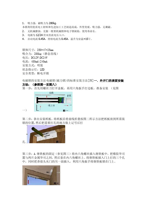
锁体尺寸:250*47*25mm吸合力:280kg(静态直线)电压:DC12V\DC24V电流:480mA\240mA安装方式:明装状态指示灯:LED安全类型:断电开锁电磁锁的安装方法电磁锁(磁力锁)的标准安装方法[图]一.外开门的表面安装方法:(参照图一至图八)第一步:首先用螺丝刀打开盖板,再用六角扳手打边板,准备安装(见图一)第二步:拿出安装纸板,将纸板沿着虚线折叠按图二所示方法把纸板放到所需装锁的位置,然后把需要打孔的地方做上记号后打孔.第三步:A.继铁板的固定(参见图三)将内六角螺丝插入继铁板中,把橡胶华司置与两片金属华司之间,然后套在内六角螺丝上。
将继铁板插入门上打的三个孔中,同时把香菇头从门的另一面插入,利用六角扳手将继铁板锁在门上。
B.边板的固定(参见图三)把边板用两个半圆头螺丝固定在先前打孔的门框上(固定在边板的长形孔中)。
注意:不要将边板锁紧,让其能前后能移动以利于安位置的修正。
C.修正边板的位置使边板与继铁板的位置合适,目的使锁主体能与继铁板紧密的接触。
D:固定锁主体与边板锁紧边板的半圆头螺丝后,再锁上所有的沉头螺丝,然后再卸下半圆头螺丝,在适当的位置钻孔以便接线。
最后用六角扳手把锁主体锁在边板上。
(参见图四)第四步:按照说明书的指示接线。
第五步:盖上盖板,把小铝柱体塞进锁主体(参见图五)的螺丝孔中。
参见图六图七与图八所示为典型的外开门外置式的安装式样★安装注意事项在安装继铁板的时候,不要把它锁紧,让其能轻微摇摆以利于和锁主体自然的结合。
二、内开门的表面安装(ZL型支架的安装方法):解决外装磁力锁的内装问题。
内开门做表面安装时需要有辅助配件来协助安装,我们选用富有装饰性的优质进口铝材来制做这种安装配件:Z&L支架。
电磁锁安装手册E-941Sx系列说明书
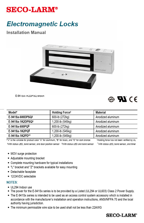
Electromagnetic LocksInstallation ManualE-941SA-1K2DPSQ shown‡With status LED, bond sensor, and door position sensor §With status LED and bond sensor**With status LED, bond sensor, and timerMOV surge protectionAdjustable mounting bracketComplete mounting hardware for typical installations "L" bracket and "Z" brackets available for easy mounting Detachable faceplate 12/24VDC selectableNOTES:UL294 Indoor useThe power for the E-941Sx series is to be provided by a Listed (UL294 or UL603) Class 2 Power Supply. The E-941Sx series is intended to be used as an access control system accessory which is installed in accordance with the manufacturer’s installation and operation instructions, ANSI/NFPA 70 and the local authority having jurisdiction.The minimum permissible wire size to be used shall not be less than 22AWGSECO-LARM Electromagnetic LocksHex-headmounting screws Steel washers x2Armature screw Mounting plate Short self-tapping screws x2Door spacer Armature plate Rubber washer Long self-tapping screws x4 Sexnut boltArmature plateholder* Electromagnet Tamper caps x2 Guide pinsParts List1x Electromagnet 1x Armature plate 2x Short self-tapping screws 1x Armature screw 2x Steel washers 1x Rubber washer 4x Long self-tapping screws 1x Sexnut bolt 2x Guide pins 1x Door spacer 2x Hex-head mounting screws 1x Mounting plate 2x Tamper caps 2x Hex wrenches 1x Armature plate holder* 1x Manual 1xTemplateSpecificationsHolding Force 600-lb1,200-lb.Operating voltage12/24 VDC Currentdraw 12VDC 500mA 24VDC 270mABond sensorSPDT relay, 1A@30VDC Door position sensor Reed switch, 0.2A@12VDC Operating temperature32°~120° F (0°~49° C)DimensionsMagnet913/16"x111/16"x1" (250x43x25 mm) 101/2"x27/16"x19/16" (267x62x40 mm) Armature71/4"x11/2"x 1/2" (185x38x12 mm) 71/4"x27/16"x5/8" (184x62x16 mm)Destructive attack Level I Line Security Level I Standby power Level I EnduranceLevel IVOverview*Armature plate holder for E-941Sx-600DPSQ and E-941Sx-1K2DPSQ onlySECO-LARM Electromagnetic LocksInstallation ApplicationsWhen mounting the electromagnet, it may be necessary to use a "Z" and "L" bracket, an"L" bracket, a "U" bracket, and/or plate spacers, depending on the location and the type of door and frame.Use the diagram below to help decide whether or not an optional bracket will be necessary for installation.Installation Notes1. Read this installation manual thoroughly. A clear understanding of the product and this manual will make installation much easier.2. The electromagnetic lock is designed for indoor use ONLY.3. The most suitable mounting location for the electromagnetic lock may require the use ofadditional SECO-LARM accessories such as Z-brackets, L-brackets, and/or spacer plates. Please see the diagram on page 3 to decide if a particular application requires any mounting accessories.4. Do not run power wires and signal wires in the same conduit as this may cause interference.5. Do not install a diode in parallel with the electromagnetic lock as this may cause a delay when releasing the door as well as cause residual magnetism.6. The best location to install the electromagnetic lock is on the inside of the door that is being secured with the wiring concealed in the frame to prevent tampering with the unit.7. The minimum permissible wire size to be used shall not be less than 22AWG.Typical InstallationPlate Spacers"L" Bracket"L" Bracket and "Z" bracket "U" BracketArmature Mounting PlateSECO-LARM Electromagnetic LocksInstallationIdeal mounting locationDoor framee a hammer to lightly tap the two guide pins into the guide pin holes on the armature plate.4.Place the template against the door and frame. Markwhere the holes are to bedrilled.Door frameTemplateDoor5.Drill holes in the frame andthe door as shown on the template and in step #6 below. The smaller holes on the door should not go all the way through. Door frameDoorSee step#6 below6.Depending on the type of door being protected, drill holes according to the diagrams below:Drill a 5/16" hole (8mm) diameter hole through the armature-plate side of the door for the armature screw. Then drill a 5/8" (16mm) diameter hole for the sexnut screw on the opposite side of the door.Drill a 1/4" hole (6.8mm) diameter and 1" (25mm) deep hole, tap for M8x1.25 thread.Drill a 5/16" hole (8mm) diameter hole in the door for the armature screw and drill a 1/2" (12.7mm) diameter and 1" (25mm) deep hole from the opposite side for the sexnut screw Reinforced doorSolid-core doorHollow metal door5/8" (16mm) 5/16" (8mm) 1/4" (6.8mm) for M8x1.25 thread 1/2516SECO-LARM Electromagnetic LocksInstallation (Continued)7.Put a rubber washer between the two metal washers and place them over the armature screw between the armature plate and the armature plate holder. This allows the plate to pivot around the screw to compensate for door misalignment.The rubber washer is sandwiched between the two metal washers and all three are placed betweenarmature plate holder.Metal washers8.Tighten the armature screw enough so that the armature plate can withstand a break-inattempt, but loose enough so that thearmature plate can pivot slightly. Make sure the anti-spin guide pins are in the two guide pin holes.Guide pinsArmature screw TIPUse a thread-locking compound on the armature screw to ensure a long-lasting installation.Guide pins9.Screw the two short self-tapping screws through the mounting plate’s slotted holes, but do not over-tighten them. Keeping them loose will allow for adjustment of the plate so that the long edge of the mounting plate and the armature plate are parallel. See the diagram below.Armature plateMounting plate90°Short self-tapping screws10.Once the mounting plate position is correct, use the four long self-tapping screws topermanently mount the mounting plate. 11.Drill the cable access hole. Run the wiring through the cable access hole in the mounting plate and through the hole in thedoor frame.SECO-LARM Electromagnetic LocksInstallation (Continued)12.Remove the cover from the front of the electromagnet. Run the power leadsthrough the large cable access hole.13.Push the electromagnet against themounting plate so the electromagnet ends are flush with the ends of the mounting plate. Use the Hex wrench to screw the hex-head mounting screws through the bottom of theelectromagnet into the mounting bracket.14.Cut the wires so they are long enough to connect with the terminal block. Set the voltage using the selection jumpers based on your input voltage. NOTESFailure to correctly set the input voltage may cause damage to the lock.Connect switching devices like push-to-exitswitches between the power source and the positive terminal on the lock. Connecting switching devices to the negative terminal may cause a delay in unlocking. Position 2 jumpers on all four pins for 12VDC operation (default)Position a jumper on the two center pins for 24VDC operationVoltage Selection Jumpers15.Connect the power and other wires according to the wiring diagram on page 7. Test the unit. Then replace the front cover and install the hex-head tamper caps (x2).NOTE: This should be the very last step after all steps are confirmed, since once the tamper caps are in place, they are verydifficult to remove.SECO-LARM Electromagnetic LocksWiring DiagramNOTESConnect switching devices like push-to-exit switches between the power source and the positive terminal of the lock. Connecting them to the negative terminal may cause a delay in unlocking.Maximum Distance from Power SourceFor a complete chart, visit Wiring DiagramA fail-safe lock unlocks when power is lost so that, in case of an emergency such as a fire in the building, the fail-safe lock will automaticallyunlock allowing personnel to escape quickly.NOTE: All field wiring must be within the protected area.Maglock (Fail-safe)* (Indoor)Key Switch (Outdoor)N/C Exit Button (Indoor) Keypad (Outdoor)Access ControlUnitControl Device+ – Power Supply 12/24 VDCN.C.COM N.O. –+= 12VDC = 24VDCVoltage jumpersSECO-LARM Electromagnetic LocksTroubleshootingDoors lock, but can easily be forced openMake sure the electromagnet and armature plates are properly aligned.Make sure the contact surfaces of the electromagnet and armature plates are clean and free from rust.Check the power leads with a meter, and make sure 12VDC or 24VDC is present.Make sure the rubber washer is installed and free from damage. Delay in door releasingThe electromagnet is fitted with a metal oxide varistor to prevent interference, so do not install a second diode.Ensure that the control device is connected between the power source and the positive terminal of the lockSECO-LARM® U.S.A., Inc.16842 Millikan Avenue, Irvine, CA 92606 Website: PITGW1LIMITED LIFETIME WARRANTY: This SECO-LARM product is warranted against defects in material and workmanship while used in normal service for the lifetime of the product. SECO-LARM’s obligation is limited to the repair or replacement of any defective part if the unit is returned, transportation prepaid, to SECO-LARM. This Warranty is void if damage is caused by or attributed to acts of God, physical or electrical misuse or abuse, neglect, repair or alteration, improper or abnormal usage, or faulty installation, or if for any other reason SECO-LARM determines that such equipment is not operating properly as a result of causes other than defects in material and workmanship. The sole obligation of SECO-LARM and the purchaser’s exclusive remedy, shall be limited to the replacement or repair only, at SECO-LARM’s option. In no event shall SECO-LARM be liable for any special, collateral, incidental, or consequential personal or property damage of any kind to the purchaser or anyone else. For all other countries, the warranty is 1 (one) year.NOTICE: The SECO-LARM policy is one of continual development and improvement. For that reason, SECO-LARM reserves the right to change specifications without notice. SECO-LARM is also not responsible for misprints. All trademarks are the property off SECO-LARM U.S.A., Inc. or their respective owners. Copyright © 2022 SECO-LARM U.S.A., Inc. All rights reserved.California Proposition 65 Warning: These products may contain chemicals which are known to the State of California to cause cancer and birth defects or other reproductive harm. For more information, go to . IMPORTANT: Users and installers of this product are responsible for ensuring that the installation and configuration of this product complies with all national, state, and local laws and codes. SECO-LARM will not be held responsible for the use of this product in violation of any current laws or codes.IMPORTANT WARNING: Incorrect mounting which leads to exposure to rain or moisture inside the enclosure could cause a dangerous electric shock, damage the device, and void the warranty. Users and installers are responsible for ensuring that this product is properly installed and sealed.。
AZM 170-11ZRK-ST-2197 24 VAC DC 电磁锁电机安装说明书

26.10.2016 06:11:04hDatasheet AZM 17011ZRKST2197 24VAC/DCSolenoid interlock / AZM 170 Preferred typ(Minor differences between the printed image and the original product may exist!)• Thermoplastic enclosure • Doubleinsulated • Compact design• 90 mm x 84 mm x 30 mm• Interlock with protection against incorrect locking.• Long life• High holding force• Manual release from side • Connector M12, 4poleOrdering detailsProduct type description AZM 17011ZRKST2197 24 VAC/DC Article number 101141425EAN code 4030661121918eCl@ss 27272603ApprovalApprovalBG USA/CAN CCCClassificationStandards EN ISO 138491B 10d Opener (NC) 2.000.000Mission time 20 Y earsnoticeGlobal PropertiesProduct name AZM 170StandardsEN 6094751, BGGSET19Compliance with the Directives (Y/N) Y es Number of actuating directions2 pieceActive principle electromechanicalDuty cycle Magnet 100 %Materials Material of the housings Plastic, glassfibre reinforced thermoplastic, selfextinguishing Material of the contacts SilverHousing coating NoneWeight295 gMechanical dataDesign of electrical connection Connector M12Mechanical life> 1.000.000 operationsEmergency unlocking device (Y/N)NoManual release (Y/N)Y es bottom rightEmergency release (Y/N)NoLatching force30 NPositive break force8.5 Npositive break travel11 mmClamping force F1000 NMax. Actuating speed2 m/sAmbient conditionsAmbient temperature Min. environmental temperature−25 °C Max. environmental temperature+60 °CProtection class IP67 to IEC/EN 60529Electrical dataDesign of control element Normally open contact (NO), Opener (NC)notice changeover contact with double break, type Zb or 2NC contacts, with galvanically separated contactbridgesSwitching principle Creep circuit elementNumber of auxiliary contacts1 pieceNumber of safety contacts1 piecePower to unlock Y esPower to lock NoRated control voltage U s24 VAC/DCPower consumption max. 10 WRated impulse withstand voltage U imp4 kVRated insulation voltage U i250 VThermal test current I the10 AUtilisation category AC15: 230 V / 4 A, DC13: 24 V / 4 AMax. fuse rating6 A gG DfuseATEXExplosion protection categories for gases NoneExplosion protected category for dusts NoneMiscellaneous dataApplicationssliding safety guard,removable guard,hinged safety guardDimensionsDimensions of the sensor Width of sensor108 mm Height of sensor75.5 mm Length of sensor30 mmnoticeIndividual coding available on requestManual release from side• For manual release using M5 triangular key, available as accessory• Additional manual release on sideDiagramNote Diagrampositive break NC contactactiveno activeNormallyopen contactNormallyclosed contactSwitch travel diagramNotes Switch travel diagramContact closedContact openSetting rangeBreak pointPositive opening sequence/ angleVS adjustable range of NO contactVÖ adjustable range of NC contactN after travelOrdering suffixThe applicable ordering suffix is added at the end of the part number of the safety switch.Order example: AZM 17011ZRKST2197 24 VAC/DC1637...16370,3 µm goldplated contacts...ST2431connector M12 , Individual solenoid monitoringOrdering codeAZM 170(1)(2)Z(3)K(4)(5)(6)(7)(1)without IDC method of terminationSK Screw connection(2)111 Normally open contact (NO) / 1 Opener (NC)022 Opener (NC)12/0.01 Normally open contact (NO), 2 Opener (NC) / (3)without Latching force 5 NR Latching force 30 NI Individual coding(4)without Power to unlockA Power to lock(5)without cable glandST Connector M12 x 1ST2431Connector M12 x 1, Individual solenoid monitoring(6)24VAC/DC U s 24 VAC/DC110VAC U s 110 VAC230VAC U s 230 VAC(7)without Manual release2197Manual release from side (Power to unlock)1637goldplated contactsAZM 170ST and AZM 170SKAZM 170ST(1)Z(2)K(3)(4)(5)024AZM 170SK(1)Z(2)K(3)(4)(5)024(1)11/111 Normally open contact (NO), 1 Opener (NC) / 1Normally open contact (NO), 1 Opener (NC) 11/021 Normally open contact (NO), 1 Opener (NC) / 2Opener (NC)12/001 Normally open contact (NO), 2 Opener (NC) / 12/111 Normally open contact (NO), 2 Opener (NC) / 1Normally open contact (NO), 1 Opener (NC) 12/021 Normally open contact (NO), 2 Opener (NC) / 2Opener (NC)02/012 Opener (NC), / 1 Opener (NC), 02/102 Opener (NC), / 1 Normally open contact (NO), (2)without Latching force 5 NR Latching force 30 N(3)without Power to unlockA Power to lock(4)1637goldplated contacts(5)2197Manual release for Power to unlockDocumentsOperating instructions and Declaration of conformity (fr) 611 kB, 29.04.2016 Code: mrl_azm170_frOperating instructions and Declaration of conformity (de) 595 kB, 25.04.2016 Code: mrl_azm170_deOperating instructions and Declaration of conformity (it) 645 kB, 09.04.2010 Code: mrl_azm170_itOperating instructions and Declaration of conformity (nl) 720 kB, 23.09.2010 Code: mrl_azm170_nlOperating instructions and Declaration of conformity (en) 611 kB, 25.04.2016 Code: mrl_azm170_enOperating instructions and Declaration of conformity (jp) 843 kB, 23.08.2016 Code: mrl_azm170_jpOperating instructions and Declaration of conformity (pl) 590 kB, 11.02.2015 Code: mrl_azm170_plOperating instructions and Declaration of conformity (da) 582 kB, 07.08.2012 Code: mrl_azm170_daOperating instructions and Declaration of conformity (es) 609 kB, 22.06.2016 Code: mrl_azm170_esBGtest certificate (en) 260 kB, 09.12.2015Code: z_m17p02BGtest certificate (de) 257 kB, 09.12.2015Code: z_m17p01CCC certification (en) 933 kB, 16.08.2016Code: q_371p02CCC certification (cn) 932 kB, 16.08.2016Code: q_371p03EAC certification (ru) 809 kB, 05.10.2015Code: q_6040p17_ruImagesDimensional drawing (basic component)Detail photoDetail photoSystem componentsActuator101122893 AZ 17/170B1• Particularly suitable for sliding doors101137406 AZ 17/170B12245• Particularly suitable for sliding doors• Damps vibration on guard device101122895 AZ 17/170B5• Particularly suitable for sliding doors101139788 AZ 17/170B11• Particularly suitable for sliding doors101139789 AZ 17/170B15• Particularly suitable for sliding doors101123391 AZM 170B6• Particularly suitable for hinged guards• For very smal actuating radii• The direction of actuation can be selected byapplicable insertion of the insertAccessories101208493 AZM 170B CENTERING GUIDE• for AZ 17 and AZM 170101100887 TRIANGULAR KEY TKM5• For manual release using M5 triangular key, availableas accessory• For maintenance, installation, etc.ConnectorAK4M12• Prewired cable• 4poleSK4M12• Connector without cable• 4poleAK4M12• Prewired cable• 4poleSK4M12• Connector without cable• 4poleK.A. Schmersal GmbH & Co. KG, Möddinghofe 30, D42279 WuppertalThe data and values have been checked throroughly. Technical modifications and errors excepted. Generiert am 26.10.2016 06:11:05h Kasbase 3.2.5.F.64I。
镇江市科捷电器 DSN-J 接地开关电磁锁 说明书

DSN-J接地开关电磁锁
1、结构
DSN(W)□型系列电磁锁按照使用功能分为电磁门锁、电磁刀闸锁和接地开关电磁锁三大类。
所有电磁锁均由机械和电气两部分组成。
机械部分包括锁体、盖板、锁栓、解锁钥匙等,电气部分包括指示灯、闭锁电磁铁、行程开关、接线座等。
电磁门锁和电磁刀闸锁可以带程序,以便与我公司生产的JSN(W)1A型机械程序锁联锁。
锁具内可以带辅助开关,以反映锁栓位置。
可以制作反相电磁锁,以满足有电闭锁、无电开销的要求(与常规电磁锁相反)。
2、安装方法
卸下锁两端M5螺母、平垫、弹垫;
从柜门内向外插入安装孔内,调整拧螺母;。
- 1、下载文档前请自行甄别文档内容的完整性,平台不提供额外的编辑、内容补充、找答案等附加服务。
- 2、"仅部分预览"的文档,不可在线预览部分如存在完整性等问题,可反馈申请退款(可完整预览的文档不适用该条件!)。
- 3、如文档侵犯您的权益,请联系客服反馈,我们会尽快为您处理(人工客服工作时间:9:00-18:30)。
电磁锁安装指南说明书
一、前言
感谢您选择本产品,本指南将详细介绍电磁锁的安装步骤以及注意事项。
请在开始安装之前仔细阅读本说明书,并按照指引进行操作。
二、电磁锁概述
电磁锁是一种常用的电动锁具,广泛应用于门禁系统中。
它由固定在门框上的锁体和安装在门上的电磁铁组成,通过电流控制锁体与电磁铁的吸合和释放。
电磁锁具有快速响应、高安全性等特点,适用于各种门控场所。
三、安装步骤
以下为电磁锁的安装步骤,请按照顺序进行操作:
1. 准备工作
在进行电磁锁安装之前,确保以下准备工作已完成:
- 确保门框和门板之间的间隙符合电磁锁的尺寸要求。
- 准备好所需的工具和安装配件,如电钻、螺丝刀、螺丝等。
- 关闭门禁系统的电源,确保操作安全。
2. 安装电磁铁
a) 选择合适的位置安装电磁铁,确保其与门上的锁体相对应。
b) 使用电钻在门上钻孔,并确保孔洞深度适合安装螺丝。
c) 将电磁铁安装在门上,通过螺丝固定并紧密连接。
3. 安装锁体
a) 选择合适的位置安装锁体,确保其与电磁铁相对应。
b) 使用电钻在门框上钻孔,并确保孔洞深度适合安装螺丝。
c) 将锁体安装在门框上,通过螺丝固定并紧密连接。
4. 接线连接
a) 定位电磁铁和锁体上的电源接线端子,并打开接线端子盖板。
b) 根据电磁锁配套的接线图,连接电源线、开关线和地线,并确保连接牢固。
c) 关闭接线端子盖板,确保接线安全可靠。
5. 调试测试
安装完成后,重新打开门禁系统的电源,并进行如下测试:
a) 测试电磁锁的吸合与释放功能,确保工作稳定可靠。
b) 测试门禁系统的开关控制,确保电磁锁与系统配合良好。
四、注意事项
在安装电磁锁时,需要注意以下事项:
1. 安全第一
在进行安装前,请确保门禁系统的电源已关闭,以免发生电击等
危险。
2. 遵循规范
按照本说明书提供的步骤进行安装,不得随意更改或省略任何步骤。
3. 注意电源适配
根据产品规格和工作电压需求,选择适当的电源接入方式。
4. 防止潮湿环境
请将电磁锁安装在防潮、干燥的环境中,避免雨水直接浸泡。
5. 定期检查维护
已安装的电磁锁需要定期检查并进行维护,保持其正常工作状态。
五、总结
本指南详细介绍了如何正确安装电磁锁,并提供了安装步骤、注意
事项等相关信息。
在安装过程中,请严格按照步骤操作,注意安全事项,以确保电磁锁的正常工作和长久使用。
祝您安装顺利,如有任何疑问,请联系本产品客服。
