电缆样本
无卤低烟电力电缆样本(优选.)

具有很高的安全特性,同时在使用和废弃处理时不会对环境造成危害。
无卤低烟低毒阻燃特性
烟密度
PH 值
电导率
阻燃等级
毒性指数
(最小透光率)≥%
≥
≤,μs/mm
60
4.3
10
A、B、C
<5
2. 导体工作温度:
长期容许工作温度:90℃
短路时最高工作温度(最长持续时间不超过 5s):250℃
3. 敷设时环境温度:不低于 0℃
1589
3635
3487
1652
1948
4499
4315
2019
2388
5816
5581
2564
3034
7218
6928
3143
3722
9174
8800
3960
4708
11651 11179
4964
5908
109
107
97
101
122
119
105
110
156
153
124
130
198
193
147
155
型号
WDN-YJY WDZCN-YJY WDZBN-YJY WDZAN-YJY WDZC-YJY23 WDZB-YJY23 WDZA-YJY23 WDZC-YJLY23 WDZB-YJLY23 WDZA-YJLY23 WDN-YJY23 WDZCN-YJY23 WDZBN-YJY23 WDZAN-YJY23 WDZC-YJY33 WDZB-YJY33 WDZA-YJY33 WDZC-YJLY33 WDZB-YJLY33 WDZA-YJLY33 WDN-YJY33 WDZCN-YJY33 WDZBN-YJY33 WDZAN-YJY33
电力光缆产品样本

539 kg/km 99 kN 0.899 Ω/km 38.4 kA2・s 13.4×10⁻⁶/℃ 153.1 kN/mm2
673 kg/km 125 kN 0.724 Ω/km 59.8 kA2・s 13.4×10⁻⁶/℃ 153.8 kN/mm2
结构:双层绞线的中心铝包钢管光纤单元结构 结构示意图 订货型号 光纤最大芯数 光纤单元规格 光缆外径 承载截面积 自重 标称抗拉强度 (RTS) 20℃直流电阻 短路电流容量 (40~200℃) 线膨胀系数 杨氏模量 OPGW(L)-1S 12(M83/R99-38) 12 芯 φ4.0 mm φ20.0 mm 234 mm2 1531 kg/km 292 kN 0.350 Ω/km 282 kA2・s 13.1×10⁻⁶/℃ 158.8 kN/mm2 OPGW(L)-1S 30(M83/R99-38) 30 芯 φ4.5 mm φ22.5 mm 295 mm2
光纤单元的结构示意图
蚊纤 疰猢 讵
荇锈 钢 畏
铝
茌层
光纤单元规格
不锈钢管直径 (mm) 2.5 2.7 3.0 3.2 3.3 3.4 3.6 3.8 中心光纤单元结构 最大光纤数量 12 20 30 36 40 40 48 48 最大光纤余长 5.0‰ 5.0‰ 5.0‰ 5.0‰ 5.0‰ 6.0‰ 6.0‰ 6.5‰ 层绞光纤单元结构 最大光纤数量 24 30 36 48 48 48 48 48 最大光纤余长 2.6‰ 2.7‰ 3.3‰ 3.0‰ 3.9‰ 4.0‰ 4.7‰ 5.2‰
结构:双层绞线的层绞不锈钢管光纤单元结构 结构示意图 订货型号 光纤最大芯数 光纤单元规格 光缆外径 承载截面积 自重 标称抗拉强度 (RTS) 20℃直流电阻 短路电流容量 (40~200℃) 线膨胀系数 杨氏模量 OPGW-2S1/30(M107/R66-97) 30 芯 φ2.7 mm φ13.85 mm 107 mm
TMC低压电缆样本
Doc.No TMCSS-05025Issued Date Dec. 22, 2005Page. No 1 of 38SPECIFICATIONDocument Title :0.6/1kV HALOGEN FREE POWER & CONTROL CABLES(FLAME RETARDANT / FIRE RESISTANCE)Type designation :0.6/1kV TI, 0.6/1kV TFOI0.6/1kV BI, 0.6/1kV BFOI1 2005. 12. 22 Revised & updated by DNV comments0 2005. 8. 22 First issueREV. DATE DESCRIPTION Prepared by Checked by Approved bySpecialized Company for Offshore&Marine CablesPage 2 of 38 1. SCOPEThis specification covers 0.6/1kV (U0/U) flame retardant or fire resistance, low smoke and halogen free power, lighting and control cables which shall be in accordance with IEC 60092-350 and IEC 60092-353.2. REFERENCE STANDARDIEC Pub. 60228 Conductors of insulated cablesIEC Pub. 60092-350 Low voltage shipboard power cablesGeneral construction and test requirementsIEC Pub. 60092-353 Single and multicore non-radial field power cables with extruded solidinsulation for rated voltage 1kV and 3kVIEC Pub. 60092-351 Insulating materials for shipboard power cables.IEC Pub. 60092-359 Sheathing materials for shipboard power and telecommunication cablesIEC Pub. 60332-1 Tests on electric cables under fire conditionsPart 1 : Test on a single vertical insulated wire or cableIEC Pub. 60332-3-22 Tests on electric cables under fire conditionsPart 3-22 : Test for vertical flame spread of vertically-mounted bunchedwires or cables - Category AIEC Pub. 60331-21 Tests for electric cables under fire conditionsPart 21 : Procedures and requirements - Cables of rated voltage up toand including 0.6/1.0kVIEC Pub. 60754-1,2 Test on gases evolved during combustion of materials from cables.Part 1 : Determination of the amount of halogen acid gas.Part 2 : Determination of degree of acidity of gases evolved duringthe combustion of materials taken from electric cables by measuringpH and conductivity.IEC 61034-1,2 Measurement of smoke density of electric cables burning under defined conditions Part 1 : Test apparatus.Part 2 : Test procedures and requirements.Page 3 of 38 3. CABLE TYPE AND DESIGNATIONThe type and symbols of cables are as given in following tables.Table 1. Type and DesignationsCable type Designation Attached table No.0.6/1kV Single ~ Multi core, XLPE insulated, SHF1 sheathed Flameretardant power & control cable0.6/1kV TI 1-1 ~ 1-7 0.6/1kV Single ~ Multi core, XLPE insulated, Lapped inner covering,Plain annealed copper wire braid armoured, SHF1 sheathed Flameretardant power & control cable0.6/1kV TFOI 2-1 ~ 2-70.6/1kV Single ~ Multi core, Mica/glass taped, XLPE insulated, SHF1sheathed Flame retardant & Fire resistance power & control cable0.6/1kV BI 3-1 ~ 3-7 0.6/1kV Single ~ Multi core, Mica/glass taped, XLPE insulated, Lappedinner covering, Plain annealed copper wire braid armoured, SHF1sheathed Flame retardant & Fire resistance power & control cable0.6/1kV BFOI 4-1 ~ 4-7Table 2. Symbols of materialsInsulation InnerCovering Armour Sheath T XLPEB Mica + XLPE FNon-hygroscopicmaterialOCopper wirebraidIHalogen free thermoplasticcompound (SHF1)4. CONSTRUCTION AND MATERIALThe construction and material of cable shall be as follows;4.1. ConductorThe conductor shall be stranded circular conductor composed of plain annealed copper wire in accordance with IEC Pub. 60228, Class2.4.2. Fire-resisting layer (Fire resistance cable only)The fire-resisting layer shall be mica/glass tape applied by lapping helically on the conductor.Page 4 of 384.3. InsulationThe insulation shall consist of an extruded layer of cross-linked polyethylene (XLPE) and shall comply with the requirement of IEC 60092-351.The average thickness of insulation shall be not less than the specified value given in the table. The thickness at any place may be less than the specified value provided the difference does not exceed0.1㎜ + 10%of the specified value.4.4. CablingThe required number of cores shall be cabled together with suitable lay length.Non-hygroscopic material may be applied to the center and the interstice between cores to form a compact circular shape. Suitable binder tape may be applied over the cabled cores.4.5. Inner covering ( TFOI & BFOI Type only )The inner covering shall be non-hygroscopic suitable tapes.The approximate thickness of the inner covering shall be 0.4mm for fictitious diameter over laid-up cores up to and including 40mm and 0.6mm for lager diameter.4.6. Armour ( TFOI & BFOI Type only )The armour shall be braided plain annealed copper wires.The diameter of wire shall comply with the value given in the table and all individual measured values shall be not smaller than 90% of the nominal value minus 0.03 mm, and not greater than 110%of the average value plus 0.03 mm.The coverage density of braid shall be not less than 90% when tested by clause 11.6 (b) ofIEC 60092-350. Suitable tape(s) may be applied over the armour at manufacturer's option.4.7. SheathThe sheath shall be an extruded layer of halogen free thermoplastic compound and shall comply with requirements of designation SHF1 in IEC 60092-359.The average thickness of the sheath shall be not less than the specified nominal value given in the table and the minimum thickness at any point shall not fall below 85%of the nominal value by more than 0.1mm.As a rule, the color of sheath shall be "Black".The other color of sheath may be applicable when purchaser required.5. IDENTIFICATIONPage 5 of 38No. of cores Method 1 (without ground core) Method 2 (with ground core) 1C Black - 2C Red , Black -3C / 3G Red , Yellow, Blue Red , Yellow, Yellow/Green4C / 4G Red , Yellow, Blue, Black Red , Yellow, Blue, Yellow/Green5 and over (5G and over) Black number on White insulationBlack number on White insulation PlusYellow/GreenNote) 1. The letter "-G" means that the cable has the earth core.2. Yellow/Green means green base colored insulation with yellow stripe.3. Any other color scheme may be applicable when purchaser required.6. TESTThe following test shall be carried out in accordance with IEC 60092-350, IEC 60092-353 and this specification.6.1.Routine testRoutine tests shall be carried out all cables manufactured, and shall be in accordance with specified standards.6.1.1.Conductor resistance test per clause 10.2 of IEC 60092-350.6.1.2. High voltage test per clause 10.3 of IEC 60092-350.6.1.3.Insulation resistance test per clause 10.4 of IEC 60092-350.6.2. Special testThe following special test shall be carried out in accordance with specified standards.6.2.1. Conductor examination test per clause 11.3 of IEC 60092-350.6.2.2. Check of dimension test per clause 11.4 to 11.7 of IEC 60092-350.6.2.3. Hot set test per clause 11.8 of IEC 60092-350.6.2.4. Low temperature test per clause 11.9 of IEC 60092-350.Page 6 of 38 6.3. Type test, electricalThe following electrical type test shall be carried out in accordance with specified standards.6.3.1. Insulation resistance test per clause 12.2 of IEC 60092-350.6.3.2. High voltage test for 4h per clause 12.4 of IEC 60092-350.6.4. Type test, non-electricalThe following non-electrical type test shall be carried out in accordance with specified standards.6.4.1. Measurement of thickness of insulation test per clause 13.1 of IEC 60092-350.6.4.2. Measurement of thickness of sheath test per clause 13.2 of IEC 60092-350.6.4.3. Non-electrical characteristics of insulation test per clause 13.3 and 13.11 ofIEC 60092-350.6.4.4. Non-electrical characteristics of sheath test per clause 13.4, 13.7, 13.8, 13.9 and 13.18 of IEC60092-350.6.4.5. Additional ageing test on pieces of completed cable per clause 13.5 of IEC 60092-350.6.4.6. Flame retardant test per IEC 60332-1.6.4.7. Flame retardant test for IEC 60332-3-22 Category A'6.4.8. Fire resisting test per IEC 60331-21. (Applied to Fire resistance cables only)6.4.9. Smoke emission test per IEC 61034-2.The minimum value shall be 60%.6.4.10. Oil Resistant(Immersion) test per clause 13.12 of IEC 60092-350. (at purchaser’s request)The test condition shall be 70±2℃, 4hour6.4.11. Cold Bending test (at -40℃) and cold impact (at -35℃) test shall be carried out inaccordance with CSA C22.2 No.38, No.0.3 (at purchaser’s request)Page 7 of 38 7. MARKING ON CABLEThe cable shall be marked with the following informations through the length of cable.The marking shall be repeated at least every 1 meter.The other information can be added in marking when purchaser required.7.1. Rated voltage7.2. Cable type7.3. Cable size7.4. Application standard (if necessary)7.5. Manufacturer's name7.6. Year of manufacture7.7. Length of cable in meterex) 0.6/1kV TFOI 95SQMM x 3C TMC 2005 0001M8. MARKING ON DRUMOn a flange of the drum, necessary information such as manufacturer's name, cable type, size, rated voltage, length of cable, drum no., gross weight, net weight, etc. shall be printed. An arrow shall be printed on the drum with suitable instructions to show the direction of rotation of the drum.9. PACKINGThe completed cable shall be placed on the wooden drum in such a manner that it will be protected from damages during transportation. The both ends of the complected cable be sealed by cap.Page 8 of 38APPENDIX ACHARACTERISTICS OF INSULATION (Comply with IEC 60092-351)Materials XLPE Maximum rated conductor temperature(℃)90Electrical characteristicsInsulation resistance constant K i(㏁·㎞)a) at 20 ℃Minimumb) at maximum operating temperature Minimum 3670 3.67Mechanical characteristics Without ageingTensile strength Minimum N/㎟ Elongation at break Minimum % 12.5 200After ageing in air ovenTemperature ℃Duration hours Tensile strengtha) Minimum value N/㎟b) Variation Maximum % Elongation at breaka) Minimum value %b) Variation Maximum % 135±2 168-±25-±25Particular characteristics Hot set testTemperature ℃Time under load Minute Mechanical stress N/㎠Elongation under load Maximum %Permanent elongation Maximum % 200±3 15 20 175 15Page 9 of 38APPENDIX BCHARACTERISTICS OF SHEATH (Comply with IEC 60092-359)Materials SHF1 Maximum rated conductor temperature(℃)85 Mechanical characteristicsWithout agingTensile strength Minimum N/㎟ Elongation at break Minimum % 9.0 120After aging in air ovenTemperature ℃Duration hours Tensile strengtha) Minimum value N/㎟b) Variation Maximum %c) Percentage of value found on the unaged specimenMinimum %Elongation at breaka) Minimum value %b) Variation Maximum %c) Percentage of value found on the unaged specimenMinimum % 100±2 1687.0 ±30-110 ±30-Particular characteristicsPressure test at high temperatureTemperature ℃ Duration under load - for cable having an outer diameter 〈 12.5mm hours - for cable having an outer diameter 〉12.5mm hours Maximum permissible deformation % 80±24 6 50Heat shock testTemperature ℃ Duration hours Result of heat shock test150±31No crackPage 10 of 38APPENDIX BCHARACTERISTICS OF SHEATH (cont)Materials SHF1Maximum rated conductor temperature(℃)85Behaviour at low temperaturesBending test(for cables with outer diameter upto and including 12.5mm)Temperature ℃ Duration hours Result of bending test-15±216 No crackElongation test (for cables not subjected to the bending test)Temperature ℃Duration hours Elongation at rupture Minimum % -15±24 20Cold impactTemperature ℃Duration hours Result of cold impact test-15±216 No crackMechanical characteristics A)After immersion in hot oil (IEC 60811-2-1. clause 10)Temperature ℃Duration hours Minimum variationa) Tensile strength %b) Elongation % 70±2 4±40 ±40Amount of halogen acid gas Maximum mg/g (%) 5 (0.5)Smoke light transmittance Minimum % 60Cold resistant (CSA C22.2 No.38, No.0.3) B)Bending testTemperature ℃ Duration hours Result of bending testCold impactTemperature ℃Duration hours Result of bending test-40±14No crack-35±14No crackDoc. No. TMCSS-05025Page 11 of 38 T a b l e1-1* CONSTRUCTION1. Conductor : Plain annealed copper wires2. Insulation : XLPE3. Sheath : SHF1* NOTE1. A suitable tape may be applied on the conductor.* REFERENCE1. Rated voltageU0/U(U m) = 0.6/1(1.2) kV2. Max. rated conductor temperature : 90℃3. Color of sheath : BlackDoc. No. TMCSS-05025Page 12 of 38 T a b l e1-21. Conductor : Plain annealed copper wires2. Insulation : XLPE5. Sheath : SHF13. Cabling (with filler)4. Binder tape* CONSTRUCTION* NOTE1. A suitable tape may be applied on the conductor.* REFERENCE1. Rated voltageU0/U(U m) = 0.6/1(1.2) kV2. Max. rated conductor temperature : 90℃3. Color of sheath : BlackDoc. No.TMCSS-05025 Page13 of 38T a b le 1-3* CONSTRUCTION 1. Conductor : Plain annealed copper wires 2. Insulation : XLPE 5. Sheath : SHF13. Cabling (with filler)4. Binder tape* NOTE1. A suitable tape may be applied on the conductor.* REFERENCE1. Rated voltageU 0/U(U m ) = 0.6/1(1.2) kV2. Max. rated conductor temperature : 90℃3. Color of sheath : BlackDoc. No. TMCSS-05025Page 14 of 38 T a b l e1-41. Conductor : Plain annealed copper wires2. Insulation : XLPE5. Sheath : SHF13. Cabling (with filler)4. Binder tape* CONSTRUCTION* NOTE1. A suitable tape may be applied on the conductor.* REFERENCE1. Rated voltageU0/U(U m) = 0.6/1(1.2) kV2. Max. rated conductor temperature : 90℃3. Color of sheath : BlackDoc. No. TMCSS-05025Page 15 of 38 T a b l e1-51. Conductor : Plain annealed copper wires2. Insulation : XLPE5. Sheath : SHF13. Cabling (with filler)4. Binder tape* CONSTRUCTION* NOTE1. A suitable tape may be applied on the conductor.* REFERENCE1. Rated voltageU0/U(U m) = 0.6/1(1.2) kV2. Max. rated conductor temperature : 90℃3. Color of sheath : BlackDoc. No. TMCSS-05025Page 16 of 38 T a b l e1-6* Cable construction is the same Attached Table 1-5Doc. No. TMCSS-05025Page 17 of 38 T a b l e1-7* Cable construction is the same Attached Table 1-5Doc. No. TMCSS-05025Page 18 of 38 T a b le2-11. Conductor : Plain annealed copper wires2. Insulation : XLPE5. Sheath : SHF13. Inner covering (lapped)4. Armour : Braid of copper wires* CONSTRUCTION* NOTE1. A suitable tape may be applied on the conductor.2. A suitable tape may be applied on the armour.3. The material of armour can be copper alloy wire forcopper wire. When purchaser required.* REFERENCE1. Rated voltageU0/U(U m) = 0.6/1(1.2) kV2. Max. rated conductor temperature : 90℃3. Color of sheath : BlackDoc. No. TMCSS-05025Page 19 of 38 Table 2-21. Conductor : Plain annealed copper wires2. Insulation : XLPE5. Armour : Braid of copper wires3. Cabling (with filler)4. Inner covering (lapped)6. Sheath : SHF1* CONSTRUCTION* NOTE1. A suitable tape may be applied on the conductor.2. A suitable tape may be applied on the armour.3. The material of armour can be copper alloy wire forcopper wire. When purchaser required.* REFERENCE1. Rated voltageU0/U(U m) = 0.6/1(1.2) kV2. Max. rated conductor temperature : 90℃3. Color of sheath : BlackDoc. No. TMCSS-05025Page 20 of 38 T a b le2-31. Conductor : Plain annealed copper wires2. Insulation : XLPE5. Armour : Braid of copper wires3. Cabling (with filler)4. Inner covering (lapped)6. Sheath : SHF1* CONSTRUCTION* NOTE1. A suitable tape may be applied on the conductor.2. A suitable tape may be applied on the armour.3. The material of armour can be copper alloy wire forcopper wire. When purchaser required.* REFERENCE1. Rated voltageU0/U(U m) = 0.6/1(1.2) kV2. Max. rated conductor temperature : 90℃3. Color of sheath : BlackDoc. No. TMCSS-05025Page 21 of 38 T a b le2-41. Conductor : Plain annealed copper wires2. Insulation : XLPE5. Armour : Braid of copper wires3. Cabling (with filler)4. Inner covering (lapped)6. Sheath : SHF1* CONSTRUCTION* NOTE1. A suitable tape may be applied on the conductor.2. A suitable tape may be applied on the armour.3. The material of armour can be copper alloy wire forcopper wire. When purchaser required.* REFERENCE1. Rated voltageU0/U(U m) = 0.6/1(1.2) kV2. Max. rated conductor temperature : 90℃3. Color of sheath : BlackDoc. No. TMCSS-05025Page 22 of 38 T a b le2-51. Conductor : Plain annealed copper wires2. Insulation : XLPE5. Armour : Braid of copper wires3. Cabling (with filler)4. Inner covering (lapped)6. Sheath : SHF1* CONSTRUCTION* NOTE1. A suitable tape may be applied on the conductor.2. A suitable tape may be applied on the armour.3. The material of armour can be copper alloy wire forcopper wire. When purchaser required.* REFERENCE1. Rated voltageU0/U(U m) = 0.6/1(1.2) kV2. Max. rated conductor temperature : 90℃3. Color of sheath : BlackDoc. No. TMCSS-05025Page 23 of 38 T a b le2-6* Cable construction is the same Attached Table 2-5Doc. No. TMCSS-05025Page 24 of 38 T a b le2-7* Cable construction is the same Attached Table 2-5Doc. No. TMCSS-05025Page 25 of 38 T a b l e3-11. Conductor : Plain annealed copper wires2. Fire resisting tape4. Sheath : SHF13. Insulation : XLPE* CONSTRUCTION* NOTE1. A suitable tape may be applied on the fire-resisting tape.* REFERENCE1. Rated voltageU0/U(U m) = 0.6/1(1.2) kV2. Max. rated conductor temperature : 90℃3. Color of sheath : BlackDoc. No. TMCSS-05025Page 26 of 38 T a b l e3-21. Conductor : Plain annealed copper wires2. Fire resisting tape5. Binder tape3. Insulation : XLPE4. Cabling (with filler)6. Sheath : SHF1* CONSTRUCTION* NOTE1. A suitable tape may be applied on the fire-resisting tape.* REFERENCE1. Rated voltageU0/U(U m) = 0.6/1(1.2) kV2. Max. rated conductor temperature : 90℃3. Color of sheath : BlackDoc. No. TMCSS-05025Page 27 of 38 T a b le3-31. Conductor : Plain annealed copper wires2. Fire resisting tape5. Binder tape3. Insulation : XLPE4. Cabling (with filler)6. Sheath : SHF1* CONSTRUCTION* NOTE1. A suitable tape may be applied on the fire-resisting tape.* REFERENCE1. Rated voltageU0/U(U m) = 0.6/1(1.2) kV2. Max. rated conductor temperature : 90℃3. Color of sheath : BlackDoc. No. TMCSS-05025Page 28 of 38 T a b l e3-41. Conductor : Plain annealed copper wires2. Fire resisting tape5. Binder tape3. Insulation : XLPE4. Cabling (with filler)6. Sheath : SHF1* CONSTRUCTION* NOTE1. A suitable tape may be applied on the fire-resisting tape.* REFERENCE1. Rated voltageU0/U(U m) = 0.6/1(1.2) kV2. Max. rated conductor temperature : 90℃3. Color of sheath : BlackDoc. No. TMCSS-05025Page 29 of 38 T a b l e3-51. Conductor : Plain annealed copper wires2. Fire resisting tape5. Binder tape3. Insulation : XLPE4. Cabling (with filler)6. Sheath : SHF1* CONSTRUCTION* NOTE1. A suitable tape may be applied on the fire-resisting tape.* REFERENCE1. Rated voltageU0/U(U m) = 0.6/1(1.2) kV2. Max. rated conductor temperature : 90℃3. Color of sheath : BlackDoc. No. TMCSS-05025Page 30 of 38 T a b l e3-6* Cable construction is the same Attached Table 3-5Doc. No. TMCSS-05025Page 31 of 38 T a b l e3-7* Cable construction is the same Attached Table 3-5Doc. No. TMCSS-05025Page 32 of 38 T a b le4-11. Conductor : Plain annealed copper wires2. Fire resisting tape5. Armour : Braid of copper wires3. Insulation : XLPE4. Inner covering (lapped)6. Sheath : SHF1* CONSTRUCTION* NOTE1. A suitable tape may be applied on the fire-resisting tape.2. A suitable tape may be applied on the armour.3. The material of armour can be copper alloy wire forcopper wire. When purchaser required.* REFERENCE1. Rated voltageU0/U(U m) = 0.6/1(1.2) kV2. Max. rated conductor temperature : 90℃3. Color of sheath : BlackDoc. No. TMCSS-05025Page 33 of 38 T a b le4-21. Conductor : Plain annealed copper wires2. Fire resisting tape6. Armour : Braid of copper wires3. Insulation : XLPE4. Cabling (with filler)7. Sheath : SHF15. Inner covering (lapped)* CONSTRUCTION* NOTE1. A suitable tape may be applied on the fire-resisting tape.2. A suitable tape may be applied on the armour.3. The material of armour can be copper alloy wire forcopper wire. When purchaser required.* REFERENCE1. Rated voltageU0/U(U m) = 0.6/1(1.2) kV2. Max. rated conductor temperature : 90℃3. Color of sheath : BlackDoc. No. TMCSS-05025Page 34 of 38 T a b le4-31. Conductor : Plain annealed copper wires2. Fire resisting tape6. Armour : Braid of copper wires3. Insulation : XLPE4. Cabling (with filler)7. Sheath : SHF15. Inner covering (lapped)* CONSTRUCTION* NOTE1. A suitable tape may be applied on the fire-resisting tape.2. A suitable tape may be applied on the armour.3. The material of armour can be copper alloy wire forcopper wire. When purchaser required.* REFERENCE1. Rated voltageU0/U(U m) = 0.6/1(1.2) kV2. Max. rated conductor temperature : 90℃3. Color of sheath : BlackDoc. No. TMCSS-05025Page 35 of 38 T a b le4-41. Conductor : Plain annealed copper wires2. Fire resisting tape6. Armour : Braid of copper wires3. Insulation : XLPE4. Cabling (with filler)7. Sheath : SHF15. Inner covering (lapped)* CONSTRUCTION* NOTE1. A suitable tape may be applied on the fire-resisting tape.2. A suitable tape may be applied on the armour.3. The material of armour can be copper alloy wire forcopper wire. When purchaser required.* REFERENCE1. Rated voltageU0/U(U m) = 0.6/1(1.2) kV2. Max. rated conductor temperature : 90℃3. Color of sheath : BlackDoc. No. TMCSS-05025Page 36 of 38 T a b le4-51. Conductor : Plain annealed copper wires2. Fire resisting tape6. Armour : Braid of copper wires3. Insulation : XLPE4. Cabling (with filler)7. Sheath : SHF15. Inner covering (lapped)* CONSTRUCTION* NOTE1. A suitable tape may be applied on the fire-resisting tape.2. A suitable tape may be applied on the armour.3. The material of armour can be copper alloy wire forcopper wire. When purchaser required.* REFERENCE1. Rated voltageU0/U(U m) = 0.6/1(1.2) kV2. Max. rated conductor temperature : 90℃3. Color of sheath : BlackDoc. No. TMCSS-05025Page 37 of 38 T a b le4-6* Cable construction is the same Attached Table 4-5Doc. No. TMCSS-05025Page 38 of 38 T a b le4-7* Cable construction is the same Attached Table 4-5。
港机电缆电子样本(新)
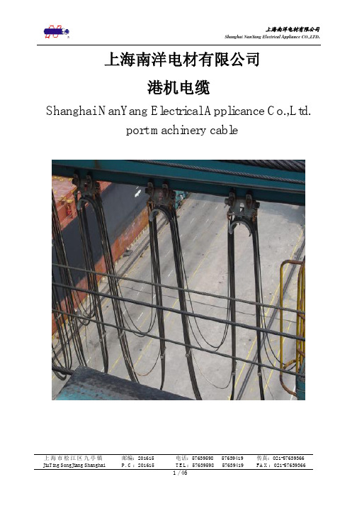
上海南洋电材有限公司
港机电缆
Shanghai NanYang Electrical Applicance Co.,Ltd. port machinery cable
上海市松江区九亭镇 JiuTing SongJiang Shanghai
轨道交通(铁路机车)车辆电缆长期为全国各机车(轨道交通)车辆厂定点提供配套, 技术性能和质量水平达到 UIC895 国际铁路联盟规范和 AARS501 美国铁路协会标准的水平。 2006 起开发了高新轨道交通电缆成功配套于我国第一代 200 公里;300 公里时速的高速动 车组。同时还试制开发了达到欧洲环境标准的低烟无卤地铁电缆为广州地铁、上海地铁等 项目配套。
在管理上建立了有效的质保和环保体系,于 1996 年获得 ISO 9002-94 标准的质量体系 证书,2002 年 11 月获得 ISO 9001-2000 标准的质量体系证书,2006 年获得了 ISO14001-2004 标准的环境体系证书。公司设有设备齐全的中心试验室,可进行物理机械性能,电气绝缘 性能、热、氧老化、单根/成束阻燃/耐火、橡胶硫化、成品曲绕以及烟气、卤素的检验测定 和导体、橡胶、塑料、化工材料的理化测定,全面保证了产品质量的稳定。
High flexible festoon optical fiber cable
拖链n cables
Energy chain control cable
拖链用屏蔽型动力电缆 Energy chain shielded power cable 拖链用动力电缆 Energy chain power cable 拖链用通讯(总线/编码)电缆 Energy chain communications (bus / coding) cable 高柔性拖链用光缆 High flexible energy chain system optical fiber cable
电缆清册样本
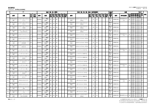
专
长度 (米)
芯 线
芯 线
芯 线
123
芯 线 4
业 标 记
版 次
50 1 2
0
备注
2
00CJF00AA001X 过热蒸汽至辅汽母管电动
B02
门已关
DI
00CRA07
四机公用#36远 程I/O
A1
A2
B2
00CJF00AA001G 过热蒸汽至辅汽母管电动门
F001
接线盒
编号
终点(盘、柜、箱、仪表、执行机构等)
端子 端子 端子 端子 端子 屏蔽 排号 号1 号2 号3 号4 端子
典型 控制 接线
图
编号
00CRA07
四机公用#36远 程I/O
A1
A1
B1
00CJF00AA001G 过热蒸汽至辅汽母管电动门
F001
接线盒
11 12
K060101
K0902C100
电缆
型号及规范
G01
门远方控制方式
DI
00CRA07
四机公用#36远 程I/O
A1
A4
B4
00CJF00AA001G 过热蒸汽至辅汽母管电动门
F001
接线盒
17 18
K060101
K0902C100
78
0
5
00CJF00AA002X B01
过热蒸汽总管电动门全开
DI
00CRA07
四机公用#36远 程I/O
A1
A5
13 14
K060101
KF00AA002X 过热蒸汽总管电动门执行
G03
机构故障
补偿电缆选型样本

补偿电缆选型样本补偿电缆选型样本补偿电缆 Compensational Cable热电偶用补偿导线、补偿导向与补偿电缆是在一定温度范围内具(包括常温)有与所匹配的热电偶的热电动势值相同的一对或多对带有绝缘层的导线或电缆,用它们连接热电偶与测量装置,以补偿它们与热电偶连接处的温度变化所产生的误差,补偿导线与补偿电缆分为延长型和补偿型两种。
Compensational Wire & Cable for ThermocoupleCompensational wire & cable are cables & wires with one pair or multi-pair and insulated layer with the same Pyro-EMF value of matched thermocouple within certain temperature. They are used to connect thermocouple and measuring devices to compensate the error resulting from temperature change on connection part. They are divided into two type including extension type and compensational type.一、生产执行标准GB/T4989-94及JB/T7495-94Executive standard: GB/T4989-94 & JB/T7495-94 Working ConditionWire & cable with fluoroplastic insulation and sheath: -60℃ for fixed installation, -20℃ for non-fixed installation Wire & cable with PVC insulation and sheath: -40℃ for fixed installation, -15℃ for non-fixed installation 3、允许弯曲半径: a)有铜带屏蔽的补偿电缆,应不小于电缆外径的16倍; b)其它结构的补偿电缆,应不小于电缆外径的10倍。
ACCC导线样本
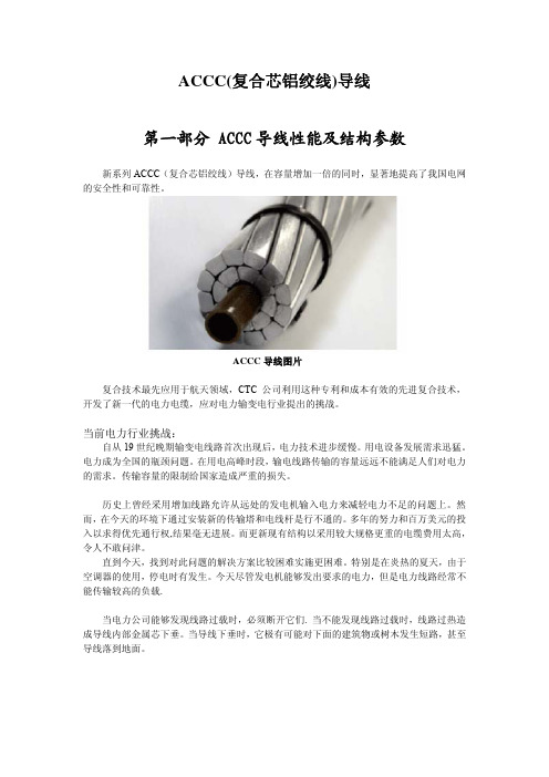
ACCC(复合芯铝绞线)导线第一部分 ACCC导线性能及结构参数新系列ACCC(复合芯铝绞线)导线,在容量增加一倍的同时,显著地提高了我国电网的安全性和可靠性。
ACCC导线图片复合技术最先应用于航天领域,CTC公司利用这种专利和成本有效的先进复合技术,开发了新一代的电力电缆,应对电力输变电行业提出的挑战。
当前电力行业挑战:自从19世纪晚期输变电线路首次出现后,电力技术进步缓慢。
用电设备发展需求迅猛。
电力成为全国的瓶颈问题。
在用电高峰时段,输电线路传输的容量远远不能满足人们对电力的需求。
传输容量的限制给国家造成严重的损失。
历史上曾经采用增加线路允许从远处的发电机输入电力来减轻电力不足的问题上。
然而,在今天的环境下通过安装新的传输塔和电线杆是行不通的。
多年的努力和百万美元的投入以求得优先通行权,结果毫无进展。
而更新现有结构以采用较大规格更重的电缆费用太高,令人不敢问津。
直到今天,找到对此问题的解决方案比较困难实施更困难。
特别是在炎热的夏天,由于空调器的使用,停电时有发生。
今天尽管发电机能够发出要求的电力,但是电力线路经常不能传输较高的负载.当电力公司能够发现线路过载时,必须断开它们. 当不能发现线路过载时,线路过热造成导线内部金属芯下垂。
当导线下垂时,它极有可能对下面的建筑物或树木发生短路,甚至导线落到地面。
运行中的ACCC导线电力行业的革新解决途径:CTC公司已经设计试验了新一代的复合芯铝绞线,它由轻型的复合芯、外层缠绕高性能的梯形成型铝线组成。
与常规的钢芯铝绞线相比,在相同的外径时,复合芯铝绞线外层允许缠绕超过28%的导电铝线。
成品重量与常规的钢芯铝绞线相似,它能够利用现有线路结构而不需改造。
复合芯铝绞线(ACCC),作为新型导线,能够传输钢芯铝绞线两倍的电流。
CTC公司生产的复合芯,经过许多独立实验室的试验,使用专利的压延工艺进行制造。
许多预拉伸的玻璃和碳纤维用高性能的热固性树脂系统予以浸渍,然后通过加热模迅速固化成形。
电缆选型样本
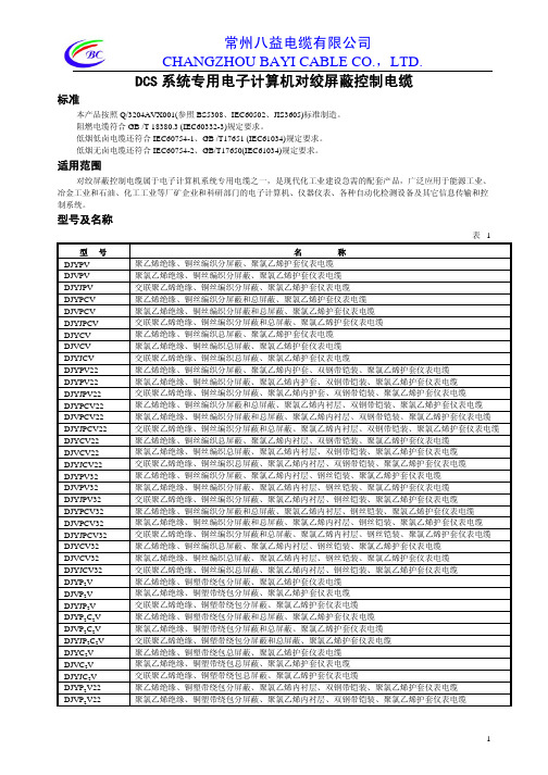
交联聚乙烯绝缘、铜丝编织分屏蔽和总屏蔽、聚氯乙烯内衬层、钢丝铠装、聚氯乙烯护套仪表电缆
聚乙烯绝缘、铜丝编织总屏蔽、聚氯乙烯内衬层、钢丝铠装、聚氯乙烯护套仪表电缆
聚氯乙烯绝缘、铜丝编织总屏蔽、聚氯乙烯内衬层、钢丝铠装、聚氯乙烯护套仪表电缆
交联聚乙烯绝缘、铜丝编织总屏蔽、表2
3
常州八益电缆有限公司 CHANGZHOU BAYI CABLE CO.,LTD.
续表2
项目
代号
说明
( 省略 )
无要求
阻燃特性
/SA
/SB
成束阻燃 低烟低卤成束阻燃
聚乙烯绝缘、铜塑带绕包分屏蔽、聚氯乙烯护套仪表电缆
聚氯乙烯绝缘、铜塑带绕包分屏蔽、聚氯乙烯护套仪表电缆
交联聚乙烯绝缘、铜塑带绕包分屏蔽、聚氯乙烯护套仪表电缆
聚乙烯绝缘、铜塑带绕包分屏蔽和总屏蔽、聚氯乙烯护套仪表电缆
聚氯乙烯绝缘、铜塑带绕包分屏蔽和总屏蔽、聚氯乙烯护套仪表电缆
交联聚乙烯绝缘、铜塑带绕包分屏蔽和总屏蔽、聚氯乙烯护套仪表电缆
聚氯乙烯绝缘、铜丝编织分屏蔽、聚氯乙烯内衬层、钢丝铠装、聚氯乙烯护套仪表电缆
交联聚乙烯绝缘、铜丝编织分屏蔽、聚氯乙烯内衬层、钢丝铠装、聚氯乙烯护套仪表电缆
聚乙烯绝缘、铜丝编织分屏蔽和总屏蔽、聚氯乙烯内衬层、钢丝铠装、聚氯乙烯护套仪表电缆
聚氯乙烯绝缘、铜丝编织分屏蔽和总屏蔽、聚氯乙烯内衬层、钢丝铠装、聚氯乙烯护套仪表电缆
交联聚乙烯绝缘、铝塑带绕包总屏蔽、聚氯乙烯护套仪表电缆
聚乙烯绝缘、铝塑带绕包分屏蔽、聚氯乙烯内衬层、双钢带铠装、聚氯乙烯护套仪表电缆
聚氯乙烯绝缘、铝塑带绕包分屏蔽、聚氯乙烯内衬层、双钢带铠装、聚氯乙烯护套仪表电缆
交联聚乙烯绝缘、铝塑带绕包分屏蔽、聚氯乙烯内衬层、双钢带铠装、聚氯乙烯护套仪表电缆
2020年(电力行业)电缆样本

(电力行业)电缆样本A架空绞线┃铝绞线(GB/T1179-2008)┃铜绞线(企业标准)┃钢绞线(GB1200-88)┃铝包钢绞线(GB/T1179-2008)┃钢芯铝绞线(GB/T1179-2008)┃铝包钢芯绞线(GB/T1179-2008)┃防腐钢芯铝绞线(GB/T1179-2008)┃扩径钢芯铝绞线(企业标准)┃铝钢扩径空芯导线(企业标准)┃耐热铝合金钢芯铝绞线(企业标准) ┃特轻型大截面钢芯铝绞线(企业标准)1 用途本系列产品适用于架空电力输配线路的电能输送,是电网的重要主要组成部分。
2 名称、型号和使用条件3 代表产品结构钢芯铝绞线铝包铜芯铝绞线线4 主要结构性能参数JL (LJ)铝绞线结构性能参数表JT (TJ)铜绞线结构性能参数表JG1A (GJ)钢绞线结构性能参数表JLB1A (JLB20A)、JLB2 (JLB27)、JLB40铝包铜绞线结构性能参数表JLHA1、JLHA2铝合金绞线结构性能参数表JL/G1A钢芯铝绞线、JL/G1AF防腐钢芯铝绞线结构性能参数表注:防腐钢芯铝绞线的计算重量,应在上表内规定值中增加防腐涂料的重量,其增值为:钢芯涂防腐涂料者增加2%,内部铝钢各层涂防腐涂料者增加3%。
JLHA1/G1A、JLHA2/G1A钢芯铝合金绞线结构性能参数表JL/LB1A(JL/LB20A)铝包钢芯铝绞线结构性能参数表NRLH60GJ耐热铝合金钢芯铝绞线结构性能参数表(导电率60%IACS)LGJQT特轻型大截面钢芯铝绞线结构性能参数表LGJK扩经钢芯铝绞线结构性能参数表LGKK铝钢扩径空芯导线结构性能参数表5 裸导体载流量在不同海拔高度及环境温度下的综合校正系数B超高压电力电缆┃额定电压66kV交联聚乙烯绝缘电力电缆(企业标准)┃额定电压110kV交联聚乙烯绝缘电力电缆(GB/T11017.2-2002)1 用途本系列产品适用于工频额定电压48/66kV及64/110kV输配电系统的电能配送。
阻燃电线电缆样本数量计算公式
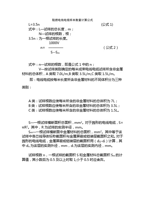
阻燃电线电缆样本数量计算公式
L=3.5n (公式1)
式中:L—试样的总长度,m;
N—试样的根数,根;
3.5n:为一根试样的长度。
1000V
n= ————(公式2)
S--S m
式中:n—试样的根数,即是公式1中的n;
V—按试样类别确定的每米成束电线电缆试样所含非金属材料的总体积,A类取7.0L/m,B类取3.5L/m,C类取1.5L/m。
即:电线电缆按每米长度所含非金属材料的不同体积分为三种类别:
A类:试样根数应使每米所含的非金属材料的总体积为7L;
B类:试样根数应使每米所含的非金属材料的总体积为3.5L;
C类:试样根数应使每米所含的非金属材料的总体积为1.5L。
S—一根试样横断面积总面积,mm2。
对于园形的电线电缆,S=πR2。
其中,R为试样的实测半径,mm。
S m—一根试样横断面中金属材料的总面积,mm2。
其中等于该试样中各芯线导体标称截面积与金属屏蔽或铠装层截面积之和。
对于园形的电线电缆,金属屏蔽或铠装层的截面积用(d O-d i)计算,其中d o 为该层的实测外径,mm,d i为该层的实测内径,mm。
试样根数n,一根试样的截面积S和金属材料总截面积S m的计算值,其小数后为0.5及以上时取1,小于0.5时应舍弃。
YJV交联聚乙烯绝缘电力电缆样本
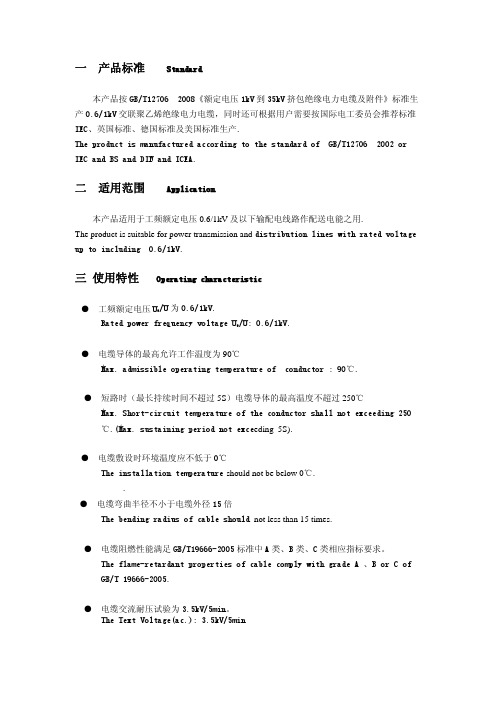
● 电缆弯曲半径不小于电缆外径 15 倍 The bending radius of cable should not less than 15 times.
Aluminum conductor XLPE insulated steel tape armoured PVC sheathed power
YJV23
cable.
For laying in doors、
铜芯交联聚乙烯绝缘钢带铠装聚乙烯护套电力电缆
in tunnels and in cable
Copper conductor XLPE insulated steel tape armoured PE sheathed power cable. trench,, able to bear external
Aluminum conductor XLPE insulated PVC sheathed power cable. 铜芯交联聚乙烯绝缘聚乙烯护套电力电缆
Copper conductor XLPE insulated PE sheathed power cable 铝芯交联聚乙烯绝缘聚乙烯护套电力电缆
For laying in doors, in tunnels and in cable trenches, able to bare external mechanical forces and certain pulling force.
五 生产范围
Production Range of Cable
● 短路时(最长持续时间不超过 5S)电缆导体的最高温度不超过 250℃ Max. Short-circuit temperature of the conductor shall not exceeding 250 ℃.(Max. sustaining period not exceeding 5S).
上缆藤仓~船用控制电缆样本
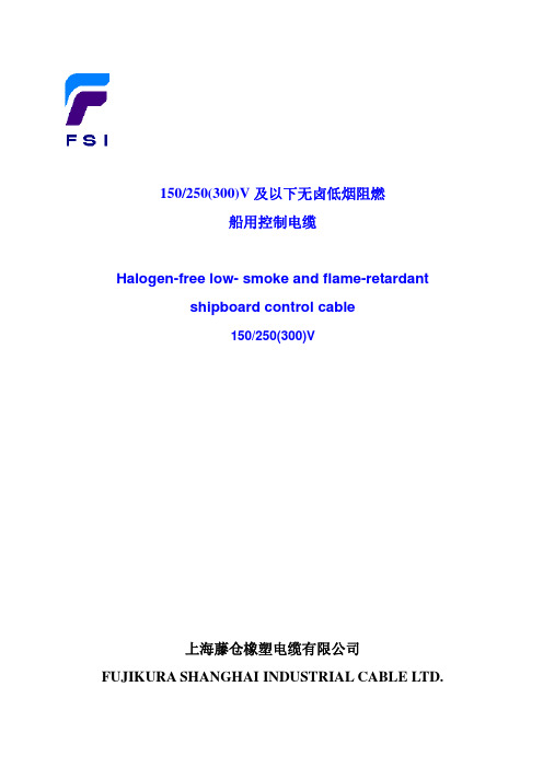
The bending radius for the cable installation
电缆结构特征 Cable construction features
电缆外径 mm Overall diameter of cable
金属编织铠装型 Metal braided armoured
非铠装型 Non-armoured
max. Ω/km
不镀锡
copper
镀锡
Tinned copper
26.0
26.3
19.2
19.3
12.8
12.9
7.86
8.02
船用电缆生产范围 Production range of shipboard cable
型号 Type (SC)
CKJPF,CKJPJ CKJ86,CKJ85 CKJPF86,CKJPJ85
14.0
132
176
238
5 x 1.5
10.5
12.0
11.2
12.5
13.9
15.5
153
201
303
7 x 1.5
11.5
12.5
12.1
13.5
14.9
16.5
192
245
356
10 x 1.5
14.5
16.0
15.7
17.0
18.1
19.5
282
389
491
12 x 1.5
15.0
16.5
电 缆 结 构 图 CONSTRUCTION OF CABLE
CKJPF/SC、CKJPJ/SC
CKJ86/SC、CKJ85/SC
1 1
YJV电力电缆规格选型

20.9 6 519. 1.83 3.08
5 × 16
5.1
1.0
1.8
23.8 839. 2 1.15 1.91
8 671.
1180 1
5 × 25 5 × 35 5 × 50
6.4
1.2
1.8
28.4 1749 943. 0.73 1.20
7.6
1.2
2.0
32.5 2318 5 0.52 0.87
e
ss
rof
Kg/km
/km
cable
Mm2
mm
Mm
Mm
Mm YJV YJL YJV YJLV KV/5min
V
4×1.5+1×1.0 4 1.38
0.7
1.8 11.8 165 - 12.1 -
1 15.8
3×300 + 1× 3*
150
1*
20.5 14.5
3×400 + 1× 3
185
1
25.7 17.6
3×400 + 1× 3*
185
1*
23.5 16.0
1.4 47.3 52.5 7991 4758 0.12 0.21
1.1
0.27 0.44
1.6 51.2 56.6 9357 5468 0.10 0.16
导体标称截面 导体直径 绝缘厚度 护套厚 电缆近似 电缆近似 导体最大直流电 试验电压
Nom.cross-sect Diammeter Insulati 度
外径
重量
阻
Test
ion
ofconduct on
Sheath Approx. Approx. Max.d.cresista Voltage(a.
耐高温电缆样本

耐高温(阻燃)电力电缆High Temperature Resistant (Flame Retardant) Power Cable本产品适用于额定电压0.6/1kV及以下的高温范围和恶劣环境内,作电气设备电能传输线。
It is used as power transmission cable for electric equipments of rated voltage 0.6/1kV or lower in bad environment or that with high temperature.一、生产执行标准采用企业标准Executive standard:enterprise standard二、使用特性Performance in Usage1、额定电压UO/U: 0.6/1kV。
2、电缆允许最高工作温度: 氟塑料绝缘及护套为200℃; 氟塑料绝缘耐热105聚氯乙烯护套为105℃;氟塑料绝缘硅橡 胶护套为180℃。
3、短路时(最长持续间不超过5S)电缆导体的最高温度不 超过250℃。
4、电缆敷设温度应不低于-15℃。
5、电缆的弯曲半径如下:单芯电缆:其弯曲半径不小于 电缆外径的20D。
三芯电缆:其弯曲半径不小于电缆外径的15D。
6、氟塑料绝缘及护套型电力电缆具有优异的耐化学腐蚀 性、耐高温及阻燃性。
1: Rated voltage UO/U: 0.6/1kV2: Max.working temperature allowed by cable is 200℃ for cable with fluoroplastic insulation and sheath, 105℃ for cable with fluoroplastic insulation,105℃ heat resistanc and PVC sheath, and 180℃ for cable with fluo-roplastic insulation and silicon rubber sheath.3: Max temperature of cable conductor is no more than 250℃ during short circuit (The longest lasting time is no more than 5s).4: Temperature for installation is no less than -15℃.5: Bending radius of cable as follows:It is no less than 20 times that of cable outer diam- eter for cable with single coreIt is no less than 15 times that of cable outer diameter for cable with 3 cores6: Power c able with f luoroplastic insulation and sheath has good features of chemical corrosion resis- tance, high temperature resistance and flame retardance.三、电缆的型号名称 Type and Description1、电缆的型号名称如表1 Type and Description in Table 1Table 1注:型号中“22”表示钢带铠装,如需钢丝铠装结构应将型号中的“22”改为“32”即可。
- 1、下载文档前请自行甄别文档内容的完整性,平台不提供额外的编辑、内容补充、找答案等附加服务。
- 2、"仅部分预览"的文档,不可在线预览部分如存在完整性等问题,可反馈申请退款(可完整预览的文档不适用该条件!)。
- 3、如文档侵犯您的权益,请联系客服反馈,我们会尽快为您处理(人工客服工作时间:9:00-18:30)。
1、瓦形线芯成缆计算公式:
两等截面圆形绝缘线芯成缆外径:D=2d
三等截面圆形绝缘线芯成缆外径:D=2.154d
四等截面圆形绝缘线芯成缆外径:D=2.414d
五等截面圆形绝缘线芯成缆外径:D=2.7d
3+1(主线为扇形),其成缆外径近似公式D=2.31h
4芯(为扇形),其成缆外径近似公式D=2.2h
3芯(为扇形),其成缆外径近似公式D=2.11h
3+2、4+1(主线为瓦形),其成缆外径近似公式D=2h+d(园形线芯外径)三大一小圆形:D=(3*d大+d小)*0.61
四大一小圆形:D=(4*d大+d小)*0.54
三大二小瓦形、四大一小瓦形:D=2.1547*h瓦高+d小
2、成缆并线模的选用计算公式:
一、圆形线芯成缆并线模的选用计算公式公式:
①、2等芯D=2d ②、3等芯D=2.16d
③、4等芯D=2.42d ④、5等芯D=2.7d
⑤、6(7)等芯D=3d ⑥、3*1芯D=2.4(3d大+d小)/4
⑦、3+2芯D=2.7(3d大+2d小)/5 ⑧、4+1芯D=2.7(4d大+d 小)/5
二、扇形线芯成缆并线模的选用计算公式公式:
①、2等芯D=2d ②、3等芯D=2.16d
③、3+1芯D=2.31(3d大+d小)/4 ④、4等芯D=2.31d
⑤、5等芯D=2.42d ⑥、4+1芯D=2.42(4d大+d小)/5 ⑦、3+2芯D=2.42(3d大+2d小)/5
例如:YJV 3×240+2×120 240线芯扇高21mm,120线芯15.2mm,那么我们成缆的理论外径为2.42×(3×21+2×15.2)÷5=45.2,我们就可以选用45mm或46mm的模具了。
注:以上D表示成缆外径,d表示圆形线芯直径或扇形高度。
为方便成缆时快速准确的选用并线模,此计算方式以作参考。
多芯电缆圆形绝缘线芯成缆外径计算公式及推导:
设绝缘线芯外径为d, 成缆外径为D,成缆外径计算公式及推导如下:
电缆直径计算公式
三大一小圆形:D=(3*d大+d小)*0.61
四大一小圆形:D=(4*d大+d小)*0.54
三大一小圆形、四大一小圆形:D=2.1547*h瓦高+d小
五大一小计算公式D=0.5*(5D大+D小)
三大四小圆形,做1+6排列,其中一小放中芯,外层大小间隔排列,外径怎么算如:ycw 3*2.5+4*0.75。
还有就是,放置中间的小线芯外径有没有要求,是大线芯外径的?%时(范围),比较全适,成缆圆整。
五大一小计算公式:D=0.5*(5D大+D小)
三大一小圆形:D=(3*d大+d小)*0.61
四大一小圆形:D=(4*d大+d小)*0.54
三大一小圆形、四大一小圆形:D=2.1547*h瓦高+d小
三大二小”线芯结构的成缆外径的计算
“三大二小”线芯结构的成缆外径的计算,通常采用查图解曲线表的方法[1],然而计算精度很难保证。
特别是利用“电子表格”进行结构计算时非常不方便。
因此,本文利用Mathcad软件的计算方法。
1.原理如图一所示,设“三大二小”的大绝缘线芯直径为d1,小绝缘线芯直径为d2,绝缘线芯的成缆外径为D。
令
:在△OO1O2中,由余弦定理得:
从图一可知:
其中:
综合(1)、(2)、(3)式得:
整理,得:
2.计算“三大二小”线芯结构的成缆外径、空隙系数及空隙面积众所周知,“三大二小”线芯结构成缆外径在区间,所以值必须在范围内。
令,则(4)变换为:
由(5)式可见,我们还不能用一般方法来求解方程的根值,然而用Mathcad软件的Root函数求解求“三大二小”线芯结构成缆外径、空隙系数及空隙面积的方程的根则非常容易。
3.计算“三大二小”线芯结构成缆外径、空隙系数的经验公式利用计算“三大二小”线芯结构成缆外径的方法,可以构成与对应表格(见a与b等关系矩阵A),同时利用Mathcad编程语言,进行多项式拟合,即得到计算“三大二小”线芯结构成缆外径的经验公式。
其程序如下:
4.结论综上所述,快速计算“三大二小”线芯结构成缆外径,不论采用图表法,还是经验公式,都能给出正确结果。
与“电子表格”软件进行结构尺寸计算相比,能收到事半功倍的效果。
希望大家喜欢,错漏之处敬请指教。
22条简单易懂的电线电缆知识...最适合新手看的哦...
1.绞合节距是电缆某元件以螺旋形旋转一周时沿轴向所前进的距离
2.绞入率是指在一个节距内单线的实际长度与绞线节距长度的差与节距长度之比
3.影响扇形绞合导体截面积的过程参数有单线根数、单线直径、绞合节距、扇形高度
4.标称截面是用以表示系列规格的一种近似的截面
5.线合导体其节距的改变是通过更换绞笼或牵引主从齿轮搭牙来实现的
6.挤塑是将配制成的塑料混合物,连续均匀挤包在导体或电缆芯上的过程
7.屏蔽是将电场磁场限制在电缆内或电缆元件内,并保护电缆免受外电场、磁场影响的屏蔽层.
8.影响挤出质量的主要因素有
1)塑料本身的质量(即原材料质量);
2)挤出机的性能;
3)挤出温度;
4)收放线张力;
5)主机及牵引速度;
6)芯线预热塑料挤出后的装置-模具(模具的几何形状结构设计和尺寸、温度高低、压力大小等主要决定)
9.绕包工序主要有1)电缆芯直径D(绕包前缆芯直径);2)绕包升角;3)绕包节距;4)绕包间隙;5)绕包带宽度
10.影响J45挤塑机绝缘线芯绝缘偏心的主要因素有1)导线不平滑或椭圆;2)模芯太大;3)模芯与模套位置未调好;4)模芯口至出口距离太短
11.电线电缆发生击穿可能的原因有1)绝缘原材料本身的介电强度不符合产品要求;2)绝缘层中含有杂质、气泡;3)电线电缆绝缘偏芯;
4)机械损伤绝缘;5)导体表面有毛刺、断头等
12.绝缘电阻与体积电阻率在概念上有绝缘电阻描述一种绝缘结构的绝缘性能,如每公里电线的绝缘电阻是多少;体积电阻率描述绝缘材料的优劣程度即绝缘特性区别
13.外护套过程检验项目有1)护套材料;2)平均厚度;3)最薄点厚度;4)护套横断面;5)工频火花试验;6)外表标志;7)外观;8)电缆外径和f值
14.f值是电缆或电缆某元件垂直于轴线的同一截面上测得的最大和最小直径之差
15.最薄点厚度是电缆某元件任一横断面上的最小厚度
16.抽样试验是制造厂按制造批量抽取完整的电线电缆,并从其上切取试样或元件进行的试验
17.成缆检查绝缘线芯质量主要有1)绝缘线芯的导线规格和结构;2)绝缘厚度和外径尺寸是否符合标准;3)绝缘颜色或打印编号是否符合标准。
4)检查产品标识及检验状态标识
18.使用工频火花机时要注意1)火花机的电极箱壳体应接地;2)试验电极的两端应接地保护电极;3)安全保护连锁装置,保证在开启试验电极时,自动断开高压电源;4)在使用前应检查安全保护连锁装置,信号铃必须能正常动作;5)操作火花机,应输出电压为零的情况下,关好电极箱,进行启动,试验电压逐步升到额定值;6)被试验电线的导电线芯或屏蔽,应可靠的接地。
若有击穿及时复位;7)应定期对火花机的输出电压的稳定性灵敏度进行校验测试等事项
19.导体、绝缘体和半导体:导电能力很强的物体称为导体。
凡不能导电的物体都叫绝缘体。
`导电性能介于导体和绝缘之间这类物体叫做半导体
20、超导体是电流在导体内流动时,由于导体本身电阻的存在,会在导体内引起发热产生损耗,从而限制了导电的能力。
有些导体在低于某一温度时,自身电阻会完全消失,我们将这类金属导体称为超导体21.电阻:电流在导体内流动时所受到的阻力称为电阻
22.批量是指批中所包含的单位产品数;样本大小是指样本中所包含的样本单位数
节径比:节径比分理论节径比和实用节径比,所谓的节径比就是节距(绞距)与直径的比值,若这个直径是节圆直径,所得的结果就是理论节径比,若采用绞合直径来计算,得到的结果就是实用节径比。
在理解理论节径比的时候,还要注意一个感念,那就是节圆!节圆就是在同一个绞合层中的导体圆心的轨迹就称为节圆,其直径就是节圆直径!就是节圆直径=绞合外径-导体直径(前提是:绞合导体的单根导体直径相等)
绞合系数:是指在一个绞合节距内,绞合单线的实际长度与绞线节距长度之比绞入率:就是指在一个绞合节距内,绞合单线的实际长度与绞合节距长度的差值与绞合节距的比值!。
