操作手册 Omega
Omega 产品用户指南说明书

e-mail:**************User’s GuideTQ504Torque TransducerShop online atINDEX1.Applications and typical attributes ...............................................Page 12.Description of the measurement system ......................................Page 12.1Mechanical design .................................................................Page 12.2Electrical design .....................................................................Page 22.3Angle-of-rotation transducer ...............................................Page 33.Electrical connection of the torque transducer ............................Page 43.1Connector pin assignments ..................................................Page 53.1.1Signals, angle outputs ...........................................................Page 63.2Laying of the output signal cables ......................................Page 63.3Placement of conductors in cable ........................................Page 64.Mechanical installation of the torque transducer........................Page 84.1Suggestions for installation ..................................................Page 85.Mechanical calibration .....................................................................Page 95.1Assembly of a simple calibrating setup............................Page 105.2Sample calculation of lever arm length.............................Page 105.3Electrical calibration.............................................................Page 116.Maintenance......................................................................................Page 117.Troubleshooting guide for transducer shaft...............................Page 12See Data Sheet for technical specificationsi1.Applications and typical attributes• Torque transducer with inductive angular position measurement system.• Measurement of constant and variable torques.• Torque measurement on a rotating shaft.• For laboratory, production and quality assurance applications.• Built- in instrument amplifier.• Built- in angle-of-rotation transducer.2.Description of the measurement system2.1Mechanical design• The transducer consists of a stator through which a bearing-mounted shaft passes.• A certain length of the shaft is utilized to convert the torque into a proportional torsional angle.• This torsional angle or angle of twist is measured between the two ends of this shaft length by an inductive (wave-form) angular position measurement system.• The inductive angular position measurement system converts the angle of twist into a proportional electrical signal.1• The electrical power for operation of the inductive angular positionmeasurement system, which rotates along with the shaft, is provided by meansof a rotary transformer.• The electrical output signal, which is proportional to the torque, is transferredto the stator by a second rotary transformer.• The connection box on the stator contains the electronics, the power supplyunit, and the instrument amplifier.2.2Electrical designThe built-in electronics comprise the following functional groups:• Oscillator for generation of the AC input voltage• Preamplifier for the output signal• Phase-sensitive rectifier for conversion of the AC output signal into a DCvoltage• Output amplifier22.3Angle-of-rotation transducer1.Rotating shaft2.Encoder disk3.Double-arm photoelectric barrier4.Open-collector output (external pull-up resistor required)*Features:• 360 slots in the encoder disk• Two double-arm photoelectric barriers 90°apart.• Number of pulses generated proportional to angle of rotation.* The ohmic value of the resistor depends on the maximum speed of rotation andthe cable length (e.g. 1500 rpm and a 4 m cable, R=3.3kΩ).33. Electrical connection of the torque transducer• Cable type: at least 12 conductors, e.g. LIYCY12 x 0.14• Max. cable length: 15 m43.1 Connector pin assignmentsDescription of interface for Type, art.-no.: 7203Angle outputs: open collector outputs with internal 10k Ωpull-up to +Vop Built in connector: Binder Series 680, type 09-0331-80-12 or equivalent Cable diagram with plugs on both sides5Top view of connector on transducer3.1.1Signals, angle outputs3.2Laying of the output signal cables-Note on safety-• Do not lay together with control lines or lines carrying a high current.• Do not lay close to strong electromagnetic fields, e.g. those of transformers,welding equipment, contactors, motors, etc.• If the above is unavoidable, the cables must be laid in grounded heavygage steel conduit.• At the transducer, lay the cables in a sling in order to prevent vibration-induced damage to them.3.3Placement of conducters in cableIn order to prevent the measurement signal being distorted by the angle pulses,the corresponding conductors should be separated within the cable.6The cable length has virtually no influence on the measurement signal, but in the case of the angle outputs the external pull-up resistances must be properly adjusted.74.Mechanical installation of the torque transducerTransducer with fixed stator:2 holes are provided in the transducer housing for this purpose.• Use displaceable couplings as both shaft ends that are capable of accommodating angular, radial and axial misalignment.• Good results have been obtained with miniature couplings stiff against torsion such as those described in data sheet 8303.At torques of 50 Nm or greater, it is also possible to install the transducer without fixed stator:• In this case, use flexible couplings at both ends.Caution:during installation no impermissibly high torques may beallowed to arise between the two ends of the torque transducer shaft.4.1Suggestions for installationTransducer with fixed stator and couplings able to accommodate angular, radial and axial misalignment at both ends.8This type of installation is possible at torques of 50 Nm and greater.5.Mechanical calibrationTo perform this, a calibration setup with lever arm and weights is needed tocreate a torque.Steps for calibration:a)Apply the rated torque to the transducer, then remove the load again.b)Precisely adjust the transducer to the zero point.c) Apply a known torque to the transducer.d) Set the indicator to the proper value.Recording of a calibration curve:a) Calibrate the transducer as described above.b) Progressively apply greater torques to the transducer in steps of 1/10 up tothe full rated torque. Then gradually remove the torque in the same way. Ateach step, wait at least 30 seconds for the torque reading to stabilize, and thenrecord.95.1A simple calibrating setup5.2Sample calculation of lever arm length10eg. m = 1 kg. Mt = 10 NmL =10Nm sec 21 kg _ 9.80665= 1,0197 m5.3Electrical calibrationA calibration control facility is integrated in the transducer to permit electrical calibration.Procedure for electrical calibration:• Remove all mechanical loads from the transducer (no torque).• Apply the calibration voltage Vc to pin K referenced to pin E.• An output signal corresponding to the rated torque will be emitted.6.Maintenance• Type IE transducers require virtually no maintenance.• The service life expectancy of the bearings within the rated temperature range is approx. 20,000 hours.• The service life expectancy of the bearing within the operating temperature range is approx. 10,000 hours.• The bearings can only be replaced in the factory.• For high-precision applications: recalibrate the transducer once annually (calibration at the factory or using an appropriate calibration setup).• Once a month, check the cable connectors to make sure that they are securely seated.• Check the cables for damage once a month.117.Troubleshooting guide for transducer shaft12ProblemProbable causesRemedial actionShaft does not rotate Bearings are defective due to:freelya) Torsional or flexional vibrations b) Excessive axial or radial loads Return to factoryc) Old or soiled bearings d) Bent shaft Zero point displacement Rotational vibration Readjust zero point on ≤2 %Shock forcesinstrument amplifier Zero offset between 2%Transducer has been overloaded The zero point can be and 5% of range Shock forcesrecalibrated once at Rotational vibrationthe instrument amplifier Transducer has Transducer has been overloaded hysteresis between by changing loads or rotational Return to factoryclockwise and counter-Rotation vibrationclockwise torqueNOTES: 13WARRANTY/DISCLAIMEROMEGA ENGINEERING, INC. warrants this unit to be free of defects in materials and workmanship for a period of 13 months from date of purchase. OMEGA’s WARRANTY adds an additional one (1) month grace period to the normal one (1) year product warranty to cover handling and shipping time. This ensures that OMEGA’s customers receive maximum coverage on each product.If the unit malfunctions, it must be returned to the factory for evaluation. OMEGA’s Customer Service Department will issue an Authorized Return (AR) number immediately upon phone or written request. Upon examination by OMEGA, if the unit is found to be defective, it will be repaired or replaced at no charge. OMEGA’s WARRANTY does not apply to defects resulting from any action of the purchaser, including but not limited to mishandling, improper interfacing, operation outside of design limits, improper repair, or unauthorized modification. This WARRANTY is VOID if the unit shows evidence of having been tampered with or shows evidence of having been damaged as a result of excessive corrosion; or current, heat, moisture or vibration; improper specification; misapplication; misuse or other operating conditions outside of OMEGA’s control. Components which wear are not warranted, including but not limited to contact points, fuses, and triacs.OMEGA is pleased to offer suggestions on the use of its various products. However, OMEGA neither assumes responsibility for any omissions or errors nor assumes liability for any damages that result from the use of its products in accordance with information provided by OMEGA, either verbal or written. OMEGA warrants only that the parts manufactured by it will be as specified and free of defects. OMEGA MAKES NO OTHER W ARRANTIES OR REPRESENTATIONS OF ANY KIND WHATSOEVER, EXPRESS OR IMPLIED, EXCEPT THAT OF TITLE, AND ALL IMPLIED WARRANTIES INCLUDING ANY WARRANTY OF MERCHANTABILITY AND FITNESS FOR A PARTICULAR PURPOSE ARE HEREBY DISCLAIMED. LIMITATION OF LIABILITY: The remedies of purchaser set forth herein are exclusive, and the total liability of OMEGA with respect to this order, whether based on contract, warranty, negligence, indemnification, strict liability or otherwise, shall not exceed the purchase price of the component upon which liability is based. In no event shall OMEGA be liable for consequential, incidental or special damages.CONDITIONS: Equipment sold by OMEGA is not intended to be used, nor shall it be used: (1) as a “Basic Component” under 10 CFR 21 (NRC), used in or with any nuclear installation or activity; or (2) in medical applications or used on humans. Should any Product(s) be used in or with any nuclear installation or activity, medical application, used on humans, or misused in any way, OMEGA assumes no responsibility as set forth in our basic WARRANTY/DISCLAIMER language, and, additionally, purchaser will indemnify OMEGA and hold OMEGA harmless from any liability or damage whatsoever arising out of the use of the Product(s) in such a manner.RETURN REQUESTS/INQUIRIESDirect all warranty and repair requests/inquiries to the OMEGA Customer Service Department. BEFORE RETU RNING ANY PRODU CT(S) TO OMEGA, PU RCHASER MU ST OBTAIN AN AU THORIZED RETU RN (AR) NU MBER FROM OMEGA’S CU STOMER SERVICE DEPARTMENT (IN ORDER TO AVOID PROCESSING DELAYS). The assigned AR number should then be marked on the outside of the return package and on any correspondence.The purchaser is responsible for shipping charges, freight, insurance and proper packaging to prevent breakage in transit.FOR WARRANTY RETURNS, please have the following information available BEFORE contacting OMEGA:1.Purchase Order number under which the productwas PURCHASED,2.Model and serial number of the product underwarranty, and3.Repair instructions and/or specific problemsrelative to the product.FOR NON-WARRANTY REPAIRS,consult OMEGA for current repair charges. Have the following information available BEFORE contacting OMEGA: 1. Purchase Order number to cover the COSTof the repair,2.Model and serial number of the product, and3.Repair instructions and/or specific problemsrelative to the product.OMEGA’s policy is to make running changes, not model changes, whenever an improvement is possible. This affords our customers the latest in technology and engineering.OMEGA is a registered trademark of OMEGA ENGINEERING, INC.© Copyright 2002 OMEGA ENGINEERING, INC. All rights reserved. This document may not be copied, photocopied, reproduced, translated, or reduced to any electronic medium or machine-readable form, in whole or in part, without the prior written consent of OMEGA ENGINEERING, INC.Where Do I Find Everything I Need for Process Measurement and Control?OMEGA…Of Course!Shop online at TEMPERATUREⅪߜThermocouple, RTD & Thermistor Probes, Connectors, Panels & AssembliesⅪߜWire: Thermocouple, RTD & ThermistorⅪߜCalibrators & Ice Point ReferencesⅪߜRecorders, Controllers & Process MonitorsⅪߜInfrared PyrometersPRESSURE, STRAIN AND FORCEⅪߜTransducers & Strain GagesⅪߜLoad Cells & Pressure GagesⅪߜDisplacement TransducersⅪߜInstrumentation & AccessoriesFLOW/LEVELⅪߜRotameters, Gas Mass Flowmeters & Flow ComputersⅪߜAir Velocity IndicatorsⅪߜTurbine/Paddlewheel SystemsⅪߜTotalizers & Batch ControllerspH/CONDUCTIVITYⅪߜpH Electrodes, Testers & AccessoriesⅪߜBenchtop/Laboratory MetersⅪߜControllers, Calibrators, Simulators & PumpsⅪߜIndustrial pH & Conductivity EquipmentDATA ACQUISITIONⅪߜData Acquisition & Engineering SoftwareⅪߜCommunications-Based Acquisition SystemsⅪߜPlug-in Cards for Apple, IBM & CompatiblesⅪߜDatalogging SystemsⅪߜRecorders, Printers & PlottersHEATERSⅪߜHeating CableⅪߜCartridge & Strip HeatersⅪߜImmersion & Band HeatersⅪߜFlexible HeatersⅪߜLaboratory HeatersENVIRONMENTALMONITORING AND CONTROLⅪߜMetering & Control InstrumentationⅪߜRefractometersⅪߜPumps & TubingⅪߜAir, Soil & Water MonitorsⅪߜIndustrial Water & Wastewater TreatmentⅪߜpH, Conductivity & Dissolved Oxygen InstrumentsM2958/0602。
Omega CN100 产品说明书

OCW-3,OMEGACARESM可将标准的2年保修期延长至5年。
CN102J-1000F,下限报警监测器,J型热电偶输入,量程0 ~ 1000°F。
CN102K-2000F,下限报警监测器,K型热电偶输入,量程0 ~ 2000°F。
M-71
CN102RTD-1000F
0 ~ 1000°F
CN101R-1650C
N/A
0 ~ 1650°C
CN101R-3000F
N/A
0 ~ 3000°F
配备操作手册。
* 填入后缀,“C”代表°C量程,“F”代表°F量程。
订购示例:CN101J-250F,上限报警监测器,J型热电偶输入,量程0 ~ 250°F。
警。每个输入通道都是独立的,具有各 自的设定值。CN100扫描每个通道,如
CN100系列
果出现报警,扫描将停止并且单个SPDT
继电器将改变状态;在按下手动复位按 钮后,扫描将恢复,该继电器恢复常 态。CN102下限报警型号还具有内置冷
CN100可接受6个热电偶或RTD输入。 探头单独销售。KQSS-14G-12。请访问
6通道监测器
经济实惠,1⁄8 DIN,上限或下限报警
CN101J-250F, 图片小于实际 尺寸。
U 持续扫描多个输入,确 定是否存在报警条件
U 多达6个单独输入
U 每个输入通道都有单独 设定值
U 需手动复位的单锁定继 电器,可限制应用
CN100温度监测器让操作人员能够持续
监测6个热电偶输入,提供上限或下限报
CN102J-1000F
0 ~ 1000°F
(24 Vdc)、3A @ 240 Vac
CN101K-500C
CN102K-500C
OMEGA用户手册 (11)
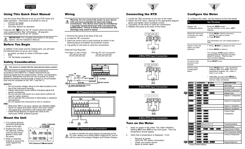
Using This Quick Start ManualUse this Quick Start Manual to set up your RTD meter and begin operation. Information is provided on how to:•Connect ac power •Connect the RTD •Set basic options for operationcharacters shown are for the “B” version.Before You BeginIn addition to the meter and the related parts, you will need the following items to set up your meter:•ac power, as listed on meter’s ID/Power Label •RTD •1/8” flat blade screwdriverSafety Considerationaccordance with EN61010-1 (Safety requirements forelectrical equipment for measurement, control, and laboratory standard). Remember that the unit has no power-on switch.Building installation should include a switch or circuit-breaker that must be compliant to IEC 947-1 and 947-3.SAFETY:•Do not exceed voltage rating on the label located on the top of the instrument housing.•Always disconnect power before changing signal and power connections.•Do not use this instrument on a work bench without its case for safety reasons.•Do not operate this instrument in flammable or explosive atmospheres.•Do not expose this instrument to rain or moisture.EMC:•Whenever EMC is an issue, always use shielded cables. •Never run signal and power wires in the same conduit.•Use signal wire connections with twisted-pair cables.•Install Ferrite Bead(s) on signal wire close to the instrument if EMC problems persist.Mount the Unit1.Cut a panel opening using the dimensions shown to the right.2.Position the unit in the opening, making sure the front bezel gasket is flush with the panel.3.Slide on retaining bracket to secure the meter against the panel.23456DP25B-RTD and DP25-RTDProgrammable Digital RTD MeterMQS3733/0206It is the policy of OMEGA to comply with all worldwide safety and EMC/EMI regulations that apply. OMEGA is constantly pursuing certification of its products to the European New Approach Directives. OMEGA will add the CE mark to every appropriate device upon certification.The information contained in this document is believed to be correct but OMEGA Engineering, Inc. accepts no liability for any errors it contains, and reserves the right to alter specifications without notice.TRADEMARK NOTICE:® ®, and,are trademarks of OMEGA WARNING:These products are not designed for use in, and should not be used for, patient connected applications.Engineering, Inc.。
Omega FL-1900系列旋阀流量表操作手册说明书

FL-1900 Series Rotameters Operator’s Manual:INSTRUCTIONSHEET M0360/0201SECTION 1 INTRODUCTION1.1GENERAL DESCRIPTIONOMEGA®Series FL-1900 Rotameters provide aneconomical and efficient means of flow rate indicationwhen accuracy is not critical. Typical applicationsinclude purging, seal oil systems, bearing lubrication,and cooling water flow indication.Engineering design makes them especially suitablefor use with corrosive liquids and gases, andinstallation in corrosive atmospheres.The Series FL-1900 Rotameters are furnished with acontrol valve, but are available without the valve.Indicator body and supported frame are constructedfrom stainless steel. Sealing parts are manufacturedfrom vinylidene fluoride resin (Kynar). O-ring sealsare Viton-A. The meter is totally enclosed within acover of high impact polycarbonate (Lexan).1.2SPECIFICATIONThe following specifications apply to all models.CAUTIONDo not use this meter in excess of the specified values PRESSURE RATINGS:200 psig maximumTEMPERATURE RATING:250°F maximumREPEATABILITY:±0.5 % of full scaleACCURACY: Meter specified to have an accuracyof ±10 % of maximum scale from100 % to 10% of scale reading.Conforms to ISA R.P. 16.1,Specification 10-S-10DIMENSION:See Figure 1.1METERING TUBE:Borosilicate glassEND FITTINGS:316SSWINDOW SHIELD:High Impact PlasticFLOA T STOPS:T eflonTUBE P ACKING:VitonO - RINGS:VitonSCALE:65mm direct reading for air or water SECTION 2 INSTALLATION2.1RECEIPT OF EQUIPMENTWhen the equipment is received, the outside packingcases should be checked for any damage incurredduring shipment. If the packing case is damaged, thelocal carrier should be notified at once regarding hisliability.Remove the envelope containing the shipping list.Carefully remove the equipment from the packingcase. Make sure spare or replacement parts are notdiscarded with the packing material. Inspect fordamaged or missing parts.2.2RETURN SHIPMENTDo not return any merchandise without an AuthorizedReturn (AR) number. Call OMEGA Customer ServiceDepartment at (203) 359-1660.CAUTIONIt is recommended that this publication be read in its entirety beforeperforming any operation. Failure to understand and follow theseinstructions could result in serious personal injury and/or damageto the equipmentWARNINGGlass metering tubes are designed for operation up to the maximum operating pressures and temperatures as specified herein. Due to the inherent brittle characteristic of glass and conditions beyond our control, tube breakage could result below specified operating conditions. Possible glass tube breakage represents a potential hazard to operating personnel; therefore, operator protection should be supplied where operating pressures may exceed 50 psig.. A safety shield constructed of 1/2inch acrylic plastic may be used or the glass tube meter maybe replaced with an all metal (armored)meter.Figure 1.1 Dimension Diagram2.3FILTER INSTALLATIONIt is recommended that a filter with a rating of two (2) micronsbe installed on the inlet side of the meter. This filter will reducethe amount of foreign matter that could impair operation ofmeter.2.4INSTALLATION OF METERa.Check the control valve is fully closed.b.Check the valve body is fully seated in meterframe. Finger tighten if necessary.c.Slowly tip meter back and forth and check thatfloat has freedom to move.d.Remove dust covers from the inlet and outlet connections.e.Install inlet and outlet line connections. Inletconnection is at the zero end of the meter.2.5CONTROL V AL VE REPOSITIONING PROCEDUREThe user may desire to change the control valve fromthe inlet side of the meter to the outlet side. If meteris installed in the line, make sure that flow is stoppedto the meter. Failure to do this may result in a safetyhazard.a.Disconnect inlet and outlet lines to meter.b.Remove metering tube and seal spindle. Refer toparagraph 4.3c.Remove check ball from inside seal spindle.Retain check ball for future use.d.Install seal spindle in meter body. Refer toparagraph 4.4e.Turn meter 180°from original position so controlvalve is now on outlet and seal spindle is on inlet.f.Install metering tube. Refer to paragraph 4.4g.Connect inlet and outlet lines to meter.SECTION 3 OPERATION3.1GENERALAfter the meter has been installed it is ready foroperation. During operation make sure that metertemperature and pressure specifications are not exceeded,as stated in paragraph 1.2When the valve stem knob is turned counterclockwise tothe stop, the valve is fully open. Flow indication ismeasured using the center of the float as the referencepoint. A check valve is incorporated within the sealspindle. The check valve prevents reverse flow throughthe meter when upstream flow is stopped. When thecontrol valve is installed on the outlet of the meter, thecheck valve is not included.SECTION 4 MAINTENANCE4.1GENERALNo periodic maintenance, oiling, or cleaning is requiredfor the meter or meter components when it is used innormal applications. It may be necessary to remove themetering tube and components for cleaning when variousliquids have stained or left a deposit.It is recommended that the meter and meter componentsbe ultrasonically cleaned if possible. If ultrasonic cleaningis not available, use a suitable solvent. Tube and float maybe cleaned with a pipe cleaner or similar accessory.Figure 4.2 Float Stop Installation DiagramModel No.Float RangeGPH W A TER*PressureDrop Inches W ater **FL-1951 FL-1952 FL-1953 FL-1954 FL-1955 FL-1956 FL-1957 FL-1958 FL-1959 FL-1960 FL-1961 FL-1962Glass316SS316SSGlass316SSGlass316SSGlass316SSGlass316SSCarboloy0.01 - 0.140.05 -0.50.1 - 1.00.05 - 0.70.10 - 1.60.2 - 2.00.5 - 4.01.0 - 9.02.0 -171.0 - 112.0 - 203.0 -301.84.019.522.318.318.745109385132525890Air Flow Given At 14.7 psia and 700 F**Pressure Drops Are ApproximateFigure 5.1 Exploded View, FL-1900。
Omega Platinum 36 MM 铂金表带说明书

DP32Pt, D P16Pt, D P8Pt温度和过程仪表本文档中所含的信息正确可信,但是 O MEGA 对于其中包含的任何错误不承担任何责任,并保留修改规格的权利,恕不另行通知。
目录1. 简介 (6)1.1 (6)1.2 注意 项 (7)1.3 接线说明 (8)1.3.1 连 (8)1.3.2 连 电 (9)1.3.3 连接输入 (9)1.3.4 带报警继电器的装置上的连 输 (11)2. 导航 (11)2.1 按钮动作说明 (11)2.2 菜单结构 (11)2.3 1 级菜单 (12)2.4 菜单循环流 (12)3. 完整菜单结构 (12)3.1 初始化模式菜单 (INIt) (12)3.2 编程模式菜单 (PRoG) (16)3.3 运行模式菜单 (oPER) (17)4. 参考章节:初始化模式 (INIt) (18)4.1 输入配置 (INIt > I NPt) (18)4.1.1 热电偶输入类型 (INIt > I NPt > t.C.) (18)4.1.2 电阻式温度检测器 (RTD) 输入类型 (INIt > I NPt > R td) (19)4.1.3 热敏电阻输入类型配置 (INIt > I NPt > t HRM) (20)4.1.4 过程输入类型配置 (INIt > I NPt > P RoC) (20)4.2 显示读数格式 (INIt > R dG) (21)4.2.1 小数点格式 (INIt > R dG > d EC.P) (21)4.2.2 温度单位 (INIt > R dG > °F°C) (21)4.2.3 滤波器 (INIt > R dG > F LtR) (22)4.2.4 标准色 (INIt > R dG > N CLR) (22)4.2.5 亮度 (INIt > R dG > b RGt) (22)4.3 激励电压 (INIt > E CtN) (22)4.4 通讯 (INIt > C oMM) (23)4.4.1 协议 (INIt > C oMM > U Sb, E tHN, S ER > P Rot) (23)4.4.2 地址 (INIt > C oMM > U Sb, E tHN, S ER > A ddR) (24)4.4.3 串行通讯参数 (INIt > C oMM > S ER >C.PAR) (24)4.5 安全功能 (INIt > S Fty) (26)4.5.1 通电确认 (INIt > S Fty > P woN) (26)4.5.2 运行模式确认 (INIt > S Fty > o PER) (26)4.5.3 设定值限值 (INIt > S Fty > S P.LM) (26)4.5.4 回路断开超时 (INIt > S Fty > L Pbk) (26)4.5.5 开路 (INIt > S Fty > o.CRk) (27)4.6 手动温度校准 (INIt > t.CAL) (27)4.6.1 动温 调 (INIt > t.CAL > N oNE) (27)4.6.2 手动温度校准偏差调整 (INIt > t.CAL > 1.PNt) (27)4.6.3 手动温度校准偏差和斜率调整 (INIt > t.CAL > 2.PNt) (27)4.6.4 温度冰点校准 (INIt > t.CAL > I CE.P) (28)4.7 将所有参数的当前配置保存在一个文件中 (INIt > S AVE) (28)4.8 加载文件中所有参数的配置 (INIt > L oAd) (28)4.9 显示固件修订编号 (INIt > V ER.N) (28)4.10 更新固件修订 (INIt > V ER.U) (28)4.11 重置为出厂默认参数 (INIt > F.dFt) (28)4.12 密码保护初始化模式访问 (INIt > I.Pwd) (29)4.13 密码保护编程模式访问 (INIt > P.Pwd) (29)5. 参考章节:编程模式 (PRoG) (29)5.1 设定值 1 配置 (PRoG > S P1) (29)5.2 设定值 2 配置 (PRoG > S P2) (29)5.3 报警模式配置 (PRoG > A LM.1, A LM.2) (30)5.3.1 报警类型 (PRoG > A LM.1, A LM.2 > t yPE) (30)5.3.2 绝对或偏差报警 (PRoG > A LM.1, A LM.2 > t yPE > A b.dV) (31)5.3.3 报警上限参考值 (PRoG > A LM.1, A LM.2 > t yPE > A LR.H) (31)5.3.4 报警下限参考值 (PRoG > A LM.1, A LM.2 > t yPE > A LR.L) (31)5.3.5 报 颜 (PRoG > A LM.1, A LM.2 > A.CLR) (32)5.3.6 报警高高/低低偏差值 (PRoG > A LM.1, A LM.2 > H I.HI) (32)5.3.7 报警锁定 (PRoG > A LM.1, A LM.2 > L tCH) (32)5.3.8 报 开 闭 (PRoG > A LM.1, A LM.2 > C tCL) (33)5.3.9 报警通电行为 (PRoG > A LM.1, A LM.2 > A.P.oN) (33)5.3.10 报警开启延迟 (PRoG > A LM.1, A LM.2 > d E.oN) (33)5.3.11 报警关闭延迟 (PRoG > A LM.1, A LM.2 > d E.oF) (33)5.4 输出通道配置 (PRoG > d tR1 或 P RoG > d tR2) (33)5.4.1 输出通道模式 (PRoG > d tR1, d tR2 > M odE) (33)6. 参考章节:运行模式 (oPER) (34)6.1 正常运行模式 (oPER > R UN) (34)6.2 更改设定值 1 (oPER > S P1) (34)6.3 更改设定值 2 (oPER > S P2) (35)6.4 清除锁定报警 (oPER > L.RSt) (35)6.5 显示最低读数 (oPER > V ALy) (35)6.6 显示最高读数 (oPER > P EAk) (35)6.7 待机模式 (oPER > S tby) (35)7. 规格 (36)7.1 输入 (36)7.2 输出(带“-‐AL” 配置,可选) (36)7.3 通讯(标配 U SB, 可选串行和以太网) (36)7.4 隔离 (36)7.5 常规 (37)8. 认证信息 (39)1.简介1.1本手册的第 1 节将介绍后面板连接和接线说明。
Omega PCL432 手持电压校准器操作手册说明书

PCL432Voltage CalibratorOperator’s ManualM1891/0994GENERAL DESCRIPTIONThe OMEGA®PCL432 Hand-Held Voltage Calibrator is designed to be a complete process voltagecalibrator delivering high accuracy in a small, easy to use package. Its microprocessor based circuitrygives the user a large number of input/output options and operating modes without unnecessarycomplexity.Commonly used outputs (up to 3) can be stored in the PCL432’s non-volitile memory for quick recall. In addition, an auto-step mode allows the calibrator to step through the selected setpoints at a user defined dwell time of 5 to 60 seconds.INSTALLATIONUNPACKINGRemove the Packing List and verify that you have received all equipment. If you have any questions about the shipment, please call the OMEGA Customer Service Department at 1-800-622-2378 or (203) 359-1660.When you receive the shipment, inspect the container and equipment for any signs of damage. Note any evidence of rough handling in transit. Immediately report any damage to the shipping agent.NOTE: The carrier will not honor any claims unless all shipping material is saved for theirexamination. After examining and removing contents, save packing material and carton in theevent reshipment is necessary.Check to see if your calibrator kit is complete. It should include:1. Carrying case (Qty=1)2. T est leads (Qty=1 set)3. 9V battery (Installed)4. Operator’s Manual (Qty=1)SET-UPBefore beginning, become familiar with the keypad layout and the configuration of the input/output jacks.Remember, these jacks are used in multiple configurations so pay careful attention to how the test leads are connected for the specific application.CJS0994RAF2BAOPERATING PROCEDURE1. Turn on power and select the desired range by depressing the “RANGE SELECT” key, then place theslide switch in the desired position (Read or Source).2. Connections are made as follows:Red Jack - Positive Input/OutputBlack Jack - Negative Input/Output3. The and keys adjust the output value up or down. Holding the ramp keys continuously forseveral seconds will increase the scroll rate. Going beyond the endpoints will cause the output to wraparound, thus allowing a quick return to either end of the scale.4. Three calibration points can be stored in non-volatile memory by scrolling to the desired output,depressing the Store key, and then the desired setpoint key.5. The auto step will automatically step through the stored setpoints at pre-defined intervals. When theauto-step key is first depressed, the display will indicate the dwell time (in seconds) between steps.The factory set value is 15 seconds but you can set this value, from 5 to 60 seconds, by usingthe and keys when the dwell time is being displayed. Once you have scrolled to the desireddwell time, release the or key and wait approximately 3 seconds until the calibrator begins toautomatically step through the 3 setpoints. The calibrator will continue the stepping process until anykey is pressed. Your chosen dwell time will remain in a non-volatile memory location until you chooseto change it.OPERATING CONSIDERATIONS AND PRECAUTIONS1. When operating in the voltage source mode, the PCL432 has the capability to drive loads up to 20 mAas shown in Figure 1.Minimum Resistance:200 mV Range - 10 ohm20 V Range - 1 KohmFigure 1 - Voltage Source Mode2. When reading a voltage, the PCL432 can measure over a range of 0-200 mV or 0-20 Volts.Connections are shown in Figure 2.Figure 2 - Voltage Loop ReadingsACCURACYThe PCL432 is checked against an NIST traceable reference before shipment to verify that each range falls within the 0.05%, ±1 count, of full scale accuracy specification. Long term accuracy should remain within 0.1%, ±1 count, of FSR. All of these ratings are based on a 25°C ambient temperature. A change of 10°C will cause approximately a 1000 ppm change (based on 100 ppm/C temp.) in the output or the equivalent of a 0.1% output change. Therefore, allowances must be made for error caused by wide temperature variations.SPECIFICATIONS Input/output Ranges0 to 200 mV 0 to 20 Volts Accuracy±0.05% ±1 LSD Maximum Load Driving±20 mA Operating Modes ReadorSource Operating T emperature0 to 50°C (32 to 122°F)Storage T emperature-20 to 60°C (-4 to 140°F)T emperature Stability0.01% F .S./°C Setpoints3 user programmed calibration points stored in non-volatile RAM.Power9V alkaline battery Auto Step FunctionT oggle through SP1, SP2 and SP3 with user defined display.Case Size1.43” x 3.15” x 5.7” (36.3 x 80.0 x 144.8mm)Weight 12 oz (340g)MAINTENANCEGenerally, with normal usage, this calibrator should hold its rated specifications for at least 6 months.Beyond this, it should remain within 0.05% of FSR over its useful life, provided it is not abused or tampered with. If after the stated warranty period, the device falls out of calibration, it can be returned to OMEGA Engineering, Inc. for re-calibration.}0-200.0 mV 0-20.00 V。
Omega 产品说明书.pdf_1718753297.219075

MQS5058/0113e-mail:**************For latest product manuals:W A R R A N T Y /D I S C L A I M E RO M E G A E N G I N E E R I N G , I N C ., w a r r e n t s t h i s u n i t t o b e f r e e o f d e f e c t s i n m a t e r i a l s a n d w o r k m a n s h i p f o r a p e r i o d o f 13 m o n t h s f r o m d a t e o f p u r c h a s e . O M E G A ’s W A R R A N T Y a d d s a n a d d i t i o n a l o n e (1) m o n t h g r a c e p e r i o d t o t h e n o r m a l o n e (1) y e a r p r o d u c t w a r r a n t y t o c o v e r h a n d l i n g a n d s h i p p i n g t i m e . T h i s e n s u r e s t h a t O M E G A ’s c u s t o m e r sr e c e i v e m a x i m u m c o v e r a g e o n e a c h p r o d u c t .I f t h e u n i t m a l f u n c t i o n s , i t m u s t b e r e t u r n e d t o t h e f a c t o r y f o r e v a l u a t i o n . O M E G A ’s C u s t o m e r S e r v i c e D e p a r t m e n t w i l l i s s u e a n A u t h o r i z e d R e t u r n (A R ) n u m b e r i m m e d i a t e l y u p o n p h o n e o r w r i t t e n r e q u e s t . U p o n e x a m i n a t i o n b y O M E G A , i f t h e u n i t i s f o u n d t o b e d e f e c t i v e , i t w i l l b e r e p a i r e d o r r e p l a c e d a t n o c h a r g e . O M E G A ’s W A R R A N T Y d o e s n o t a p p l y t o d e f e c t s r e s u l t i n g f r o m a n y a c t i o n o f t h e p u r c h a s e r , i n c l u d i n g b u t n o t l i m i t e d t o m i s h a n d l i n g , i m p r o p e r i n t e r f a c i n g , o p e r a t i o n o u t s i d e o f d e s i g n l i m i t s , i m p r o p e r r e p a i r , o r u n a u t h o r i z e d m o d i fi c a t i o n . T h i s W A R R A N T Y i s V O I D i f t h e u n i t s h o w s e v i d e n c e o f h a v i n g b e e n t a m p e r e d w i t h o r s h o w s e v i d e n c e o f h a v i n g b e e n d a m a g e d a s a r e s u l t o f e x c e s s i v e c o r r o s i o n ; o r c u r r e n t , h e a t , m o i s t u r e o r v i b r a t i o n ; i m p r o p e r s p e c i fi c a t i o n ; m i s a p p l i c a t i o n ; m i s u s e o r o t h e r o p e r a t i n g c o n d i t i o n s o u t s i d e o f O M E G A ’s c o n t r o l . C o m p o n e n t s i n w h i c hw e a r i s n o t w a r r a n t e d , i n c l u d e b u t a r e n o t l i m i t e d t o c o n t a c t p o i n t s , f u s e s , a n d t r i a c s .O M E G A i s p l e a s e d t o o f f e r s u g g e s t i o n s o n t h e u s e o f i t s v a r i o u s p r o d u c t s . H o w e v e r , O M E G A n e i t h e r a s s u m e s r e s p o n s i b i l i t y f o r a n y o m i s s i o n s o r e r r o r s n o r a s s u m e s l i a b i l i t y f o r a n y d a m a g e s t h a t r e s u l t f r o m t h e u s e o f i t s p r o d u c t s i n a c c o r d a n c e w i t h i n f o r m a t i o n p r o v i d e d b y O M E G A , e i t h e r v e r b a l o r w r i t t e n . O M E G A w a r r a n t s o n l y t h a t t h e p a r t s m a n u f a c t u r e d b y t h e c o m p a n y w i l l b e a s s p e c i fi e d a n d f r e e o f d e f e c t s . O M E G A M A K E S N O O T H E R W A R R A N T I E S O R R E P R E S E N T A T I O N S O F A N Y K I N D W H A T S O E V E R , E X P R E S S E D O R I M P L I E D , E X C E P T T H A T O F T I T L E , A N D A L L I M P L I E D W A R R A N T I E S I N C L U D I N G A N Y W A R R A N T Y O F M E R C H A N T A B I L I T Y A N D F I T N E S S F O R A P A R T I C U L A R P U R P O S E A R E H E R E B Y D I S C LA I M E D . L I M I T A T I O N O F L I AB I L I T Y : T h e r e m e d i e s o f p u r c h a s e r s e t f o r t h h e r e i n a r e e x c l u s i v e , a n d t h e t o t a l l i a b i l i t y o f O M E G A w i t h r e s p e c t t o t h i s o r d e r , w h e t h e r b a s e d o n c o n t r a c t , w a r r a n t y , n e g l i g e n c e , i n d e m n i fi c a t i o n , s t r i c t l i a b i l i t y o r o t h e r w i s e , s h a l l n o t e x c e e d t h e p u r c h a s e p r i c e o f t h e c o m p o n e n t u p o n w h i c h l i a b i l i t y i s b a s e d . I n n oe v e n t s h a l l O M E G A b e l i a b l ef o r c o n s e q u e n t i a l , i n c i d e n t a l o r s p e c i a l d a m ag e s .C O ND I T I O N S :E q u i p m e n t s o l d b y O M E G A i s n o t i n t e n d e d t o b e u s e d , n o r s h a l l i t b e u s e d : (1) a s a “B a s i c C o m p o n e n t ” u n d e r 10 CF R 21 (N R C ), u s e d i n o r w i t h a n y n u c l e a r i n s t a l l a t i o n o r a c t i v i t y ; o r (2) i n m e d i c a l a p p l i c a t i o n s o r u s e d o n h u m a n s . S h o u l d a n y P r o d u c t (s ) b e u s e d i n o r w i t h a n y n u c l e a r i n s t a l l a t i o n o r a c t i v i t y , m e d i c a l a p p l i c a t i o n , u s e d o n h u m a n s , o r m i s u s e d i n a n y w a y , O M EG A a s s u m e s n o r e s p o n s i b i l i t y a s s e t f o r t h i n o u r b a s i c W A R R A N T Y /D I S C L A I M E R l a n g u a g e , a n d , a d d i t i o n a l l y , p u r c h a s e r w i l l i n d e m n i f y O M E G A a n d h o l d O M E G A h a r m l e s s f r o m a n y l i a b i l i t y o r d a m a g e w h a t s o e v e r a r i s i n g o u to f t h e u s e o f t h e P r o d u c t (s ) i n s u c h a m a n n e r .R E T U R N R E Q U E S T S /I N Q U I R I E SD i r e c t a l l w a r r a n t y a n d r e p a i r r e q u e s t s /i n q u i r i e s t o t h e O ME G A C u s t o m e r S e r v i c eD e p a r t m e n t . BEF O R E R E T U R N I NG A N Y P R O D U C T (S ) T O O M E G A , P U R CH A S E R M U S T O B T AI N A N A U T H O R I Z E D R E T U R N (A R ) N U M B E R F R O M O M E G A ’S C U S T O M E R S E R V I C E D E P A R T M E N T (I N O R D E R T O A V O I D P R O C E S S I N G D E L A Y S ). T h e a s s i g n e d A R n u m b e r s h o u l d t h e n b e m a r k e d o n t h e o u t s i d e o f t h e r e t u r n p a c k a g e a n d o n a n y c o r r e s p o n d e n c e .T h e p u r c h a s e r i s r e s p o n s i b l e f o r s h i p p i n g c h a r g e s , f r e i g h t , i n s u r a n c e a n d p r o p e rp a c k a g i n g t o p r e v e n t b r e a k a g e i n t r a n s i t .F O R W A R R A N T Y R E T U R N S , p l e a s e h a v e t h e f o l l o w i n g i n f o r m a t i o n a v a i l a b l e B E F O R E c o n t a c t i n g O M EG A .1. P u r c h a s e o r d e r n u m b e r w h i c h t h e p r o d u c t w a s P U R CH A S E D ,2. M o d e l a n d s e r i a l n u m b e r o f t h e p r o d u c t u n d e r w a r r a n t y , a n d 3. R e p a i r i n s t r u c t i o n s a n d /o r s p e c i fi c p r o b l e m s r e l a t i v e t o t h e p r o d u c t .O M E G A ’s p o l i c y i s t o m a k e r u n n i n g c h a n g e s , n o t m o d e l c h a n g e s , w h e n e v e r a ni i m p r o v e m e n t i s p o s s i b l e . T h i s a f f o r d s c u s t o m e r s t h e l a t e s t t e c h n o o g y a n d e n g i n e e r i n g .O M E G A i s a r e g i s t e r e d t r a d r m a r k o f O M E G A E N G I N E E R I N G , I N C .© C O P Y R I G H T 2013 O M E G A E N G I N E E R I N G , I N C . A l l r i g h t s r e s e r v e d . T h i s d o c u m e n t m a y n o t b e c o p i e d , p h o t o c o p i e d , t r a n s l a t e d , o r r e d u c e d t o a n y e l e c t r o n i c m e d i u m -r e a d a b l e f o r m , i n w h o l e o r i n p a r t , w i t h o u t t h e p r i o r w r i t t e n c o n s e n t o f O M E G AE N G I N E E R I N G , I N C .F O R N O N -W A R R A N T Y R E T U R N S , c o n s u l tO M E G A f o r c u r r e n t r e p a i r c h a r g e s . H a v et h e f o l l o w i n g i n f o r m a t i o n a v a i l a b l e B E F O R Ec o n t a c t i n g O M E G A .1. P u r c h a s e O r d e r n u m b e r t o c o v e r t h eC O S T o f t h e r e p a i r ,2. M o d e l a n d s e r i a l n u m b e r o f t h e p r o d u c t a n d3. R e p a i r i n s t r u c t i o n s a n d /o r s p e c i fi c p r o b l e m sr e l a t i v e t o t h e p r o d u c t .U .S .A .:O m e g a E n g i n e e r i n g I n c ., O n e O m e g a D r i v e , P .O .B o x 4047I S O 9001 C e r t i fi e dS t a m f o r d , C T 06907-0047 U S AT o l l -F r e e : 1-800-826-6342 T E L : (203) 359-1600F A X : (203) 359-7700 e -m a i l : i n f o @o m e g a .c o mC a n a d a :976 B e r g a rL a v a l (Q u e b e c ) H 7L 5A 1, C a n a d aT o l l -F r e e : 1-800-826-6342 T E L : (514) 856-6928F A X : (514) 856-6886 e -m a i l : i n f o @o m e g a .c o mF o r i m m e d i a t e t e c h n i c a l o r a p p l i c a t i o n a s s i s t a n c e :U .S .A . a n d C a n a d a : S a l e s S e r v i c e : 1-800-826-6342/1-800-T C -O M E G AC u s t o m e r S e r v i c e : 1-800-622-2378/1-800-622-B E S T E n g i n e e r i n g S e r v i c e : 1-800-872-9436/1-800-U S A -W H E N M e x i c o /T E L : 001 (203) 359-1660 F A X : 001 (203) 359-7700L a t i n A m e r i c a :e -m a i l : e s p a n o l @o m e g a .c o mS e r v i c i n g C h i n a :C h i n a :1698 Y i S h a n R o a d , U n i t 102M i n H a n g D i s t r i c tS h a n g h a i , C h i n a 201103 P .R .C . H o t l i n e : 800 819 0559/400 619 0559e -m a i l : i nf o @c n .o m eg a .c o mS e r v i c i n g E u r o p e :B e n e l u x :T o l l -F r e e : 0800 099 3344 T E L : +31 20 347 21 21 F A X : +31 20 643 46 43e -m a i l : s a l e s @o m e g a e n g .n lC z e c h R e p u b l i c :F r y s t a t s k a 184733 01 K a r v i n á, C z e c h R e p u b l i cT E L : +420-59-6311899 F A X : +420-59-6311114 e -m a i l : i n f o @o m e g a s h o p .c zF r a n c e :T o l l -F r e e : 0805 541 038 T E L : 01 57 32 48 17F A X : 01 57 32 48 18e -m a i l : e s a l e s @o m e g a .f rG e r m a n y /A u s t r i a :D a i m l e r s t r a s s e 26D -75392 D e c k e n p f r o n n , G e r m a n yT o l l -F r e e : 0800 8266342 T E L : +49 (0) 7056 9398-0F A X : +49 (0) 7056 9398-29 e -m a i l : i n f o @o m e g a .d eU n i t e r K i n g d o m : O M E G A E n g i n e e r i n g , L t d .I S O 9001 C e r t i fi i e dO n e O m e g a D r i v e , R i v e r B e n d T e c h n o l o g y C e n t r e , N o r t h b a n kI r l a m , M a n c h e s t e r M 44 5B D U n i t e d K i n g d o mT o l l -F r e e : 0800-488-488 T E L : +44 (0) 161 777-6611F A X : +44 (0) 161 777-6622 e -m a i l : s a l e s @o m e g a .c o .u kI t i s t h e p o l i c y o f O M E G A E n g i n e e r i n g , I n c . t o c o m p l y w i t h a l l w o r l d w i d e s a f e r y a n d E M C /E M I r e g u l a t i o n s t h a t a p p l y . O M E G A i s c o n s t a n l y p u r s u i n g c e r t i fi c a t i o n o f i t s p r o d u c t s t o t h e E u r o p e a n N e w A p p r o a c h D i r e c t i v e s . O M E G A w i l l a d d t h e C E m a r k t o e v e r y a p p r o p r i a t e d e v i c e u p o n c e r t i fi c a t i o n .T h e i n f o r m a t i o n c o n t a i n e d i n t h i s d o c u m e n t i s b e l i e v e d t o b e c o r r e c t , b u t O M E G A a c c e p t s n o l i a b i l i t y f o r a n ye r r o r s i t c o n t a i n s , a n d r e s e r v e s t h e r i g h t t o a l t e r s p e c i fi c a t i o n s w i t h o u t n o t i c e .W A R N I N G : T h e s e p r o d u c t s a r e n o t d e s i g n e d f o r u s e i n , a n d s h o u l d n o t b e u s e d , f o r h u m a n a p p l i c a t i o n s .Where Do I Find Everything I Need for Process Measurement and Control?OMEGA... Of Course!Shop online at SMTEMPERATUREThermocouple RTD & Thermister Probes Connectors, Panels & Assemblies Wire: Thermocouple, RTD & Thermister Calibrators & Ice Point References Recorders, Controllers & Process Monitors Infrared PyrometersPRESSURE, STRAIN AND FORCETransducers & Strain Gages Load Cells & Pressure Gages Displacement Transducers Instumentation & AccessoriesFLOW/LEVELRotameters Gas Mass Flowmeters & FlowComputers Air Velocity Indicators Turbine/Paddlewheel Systems Totalizers & Batch ControllersPH/CONDUCTIVITYpH Electrodes Testers & Accessories Benchtop/Laboratory Meters Controllers, Calibrators, Simulators & Pumps Industrial pH & Conductivity EquipmentDATA ACQUISTIONData Acquistion & Engineering Software Communications-Based Acquistion Systems Plug-in Cards for Apple, IBM, & Compatibles Data Logging Systems Recorders, Printers, & PlottersHEATERSHeating Cable Cartridge & Strip Heaters Immersion & Band Heaters Flexible Heaters Laboratory HeatersENVIRONMENTALMONITORING AND CONTROLMetering & Control Instrumentation Refractometers Pumps & Tubing Air, Soil & Water Monitors Industrial Water & Wastewater Treatment pH Conductivity & Dissolved Oxygen InstrumentsOM-EL-ENVIROPAD-TCThermometer With Built-inData Logging and GraphingCopyright Omega Engineering, Inc. 2013 Issue 1 01/13Connecting The ThermocoupleTo turn on simply press the button situated below the screen. To turn off, press and hold the button.There is a thermocouple connector port at the top of the OM-EL-ENVIROPAD-TC logging pad. Insert the thermocouple into this port.The device is configured to a K type probe. If you wish to use a J, N or T type probe select the button and choose the correct probe type.Select the button to record and save temperature readings as and when required.Spot Check MeasurementViewing Previous DataSettingsData LoggingSelect the button to record and save temperature readings at set intervals. Full Set-Up includes selecting sample rate, setting alarms and when you want the device to start recording data Quick Set-Up takes you straight to recording data.Select the button to view previouslysaved data and choose the required file. Data can be viewed in a graphical or table format.Select the button to set temperature units, time, date and probe type.Transfer Data onto a PCRechargingConnect the OM-EL-ENVIROPAD-TC logging pad to the PC via the USB cable provided.The PC will detect that the device has been connected. Locate the files from the OM-EL-ENVIROPAD-TC drive you wish to download and copy them to your PC. Files can be opened in Excel ® for further analysis.The cable provided with the device is used for data transfer and recharging. The OM-EL-ENVIROPAD-TC logging pad will automatically start recharging once it is connected to a PC or USB mains adapter .。
OMEGA DPF6000 DPF5000产品说明书

User’s GuideShop on line ate-mail:**************It is the policy of OMEGA to comply with all worldwide safety and EMC/EMI regulations that apply. OMEGA is constantly pursuing certification of its products to the European New Approach Directives. OMEGA will add the CE mark to every appropriate device upon certification.The information contained in this document is believed to be correct, but OMEGA Engineering, Inc. accepts no liability for any errors it contains, and reserves the right to alter specifications without notice.WARNING: These products are not designed for use in, and should not be used for, patient-connected applications.This device is marked with the international caution symbol. It is important to read the Setup Guide before installing or commissioning this device as the guide contains important information relating to safety and EMC.This device is marked with the international caution symbol. It is important to read the Setup Guide before installing or commissioning this device as the guide containsimportant information relating to safety and EMC.!NOTES:___________________________________________________________________________ ___________________________________________________________________________ ___________________________________________________________________________ ___________________________________________________________________________ ___________________________________________________________________________ ___________________________________________________________________________ ___________________________________________________________________________ ___________________________________________________________________________ ___________________________________________________________________________ ___________________________________________________________________________ ___________________________________________________________________________ ___________________________________________________________________________ ___________________________________________________________________________ ____________________________________________________________________________ ____________________________________________________________________________ ____________________________________________________________________________ ____________________________________________________________________________ ____________________________________________________________________________ ____________________________________________________________________________ ____________________________________________________________________________ ___________________________________________________________________________ ___________________________________________________________________________ ___________________________________________________________________________ ___________________________________________________________________________ ___________________________________________________________________________ ___________________________________________________________________________ ___________________________________________________________________________ ___________________________________________________________________________ ___________________________________________________________________________ ___________________________________________________________________________ ___________________________________________________________________________ ____________________________________________________________________________ __________________________________________________________________________ ___________________________________________________________________________11NOTES:___________________________________________________________________________ ___________________________________________________________________________ ___________________________________________________________________________ ___________________________________________________________________________ ___________________________________________________________________________ ___________________________________________________________________________ ___________________________________________________________________________ ___________________________________________________________________________ ___________________________________________________________________________ ___________________________________________________________________________ ___________________________________________________________________________ ___________________________________________________________________________ ___________________________________________________________________________ ____________________________________________________________________________ ____________________________________________________________________________ ____________________________________________________________________________ ____________________________________________________________________________ ____________________________________________________________________________ ____________________________________________________________________________ ____________________________________________________________________________ ___________________________________________________________________________ ___________________________________________________________________________ ___________________________________________________________________________ ___________________________________________________________________________ ___________________________________________________________________________ ___________________________________________________________________________ ___________________________________________________________________________ ___________________________________________________________________________ ___________________________________________________________________________ ___________________________________________________________________________ ___________________________________________________________________________ ____________________________________________________________________________ __________________________________________________________________________ ___________________________________________________________________________15Direct all warranty and repair requests/inquiries to the OMEGA Customer Service Department. BEFORE RETURNING ANY PRODUCT(S) TO OMEGA, PURCHASER MUST OBTAIN AN AUTHORIZED RETURN (AR) NUMBER FROM OMEGA’S CUSTOMER SERVICE DEPARTMENT (IN ORDER TO AVOID PROCESSING DELAYS). The assigned AR number should then be marked on the outside of the return package and on any correspondence.The purchaser is responsible for shipping charges, freight, insurance and proper packaging to prevent breakage in transit.FOR WARRANTY RETURNS, please have the following information available BEFORE contacting OMEGA:1.Purchase Order number under which the productwas PURCHASED,2.Model and serial number of the product underwarranty, and3.Repair instructions and/or specific problemsrelative to the product.FOR NON-WARRANTY REPAIRS,consult OMEGA for current repair charges. Have the following information available BEFORE contacting OMEGA:1. Purchase Order number to cover the COSTof the repair,2.Model and serial number of product, and3.Repair instructions and/or specific problemsrelative to the product.OMEGA’s policy is to make running changes, not model changes, whenever an improvement is possible. This affords our customers the latest in technology and engineering.OMEGA is a registered trademark of OMEGA ENGINEERING, INC.© Copyright 2007 OMEGA ENGINEERING, INC. All rights reserved. This document may not be copied, photocopied, reproduced, translated, or reduced to any electronic medium or machine-readable form, in whole or in part, without the prior written consent of OMEGA ENGINEERING, INC.Where Do I Find Everything I Need forProcess Measurement and Control?OMEGA…Of Course!Shop on line at TEMPERATUREⅪߜThermocouple, RTD & Thermistor Probes, Connectors, Panels & AssembliesⅪߜWire: Thermocouple, RTD & ThermistorⅪߜCalibrators & Ice Point ReferencesⅪߜRecorders, Controllers & Process MonitorsⅪߜInfrared PyrometersPRESSURE,STRAIN AND FORCEⅪߜTransducers & Strain GaugesⅪߜLoad Cells & Pressure GaugesⅪߜDisplacement TransducersⅪߜInstrumentation & AccessoriesFLOW/LEVELⅪߜRotameters, Gas Mass Flowmeters & Flow ComputersⅪߜAir V elocity IndicatorsⅪߜTurbine/Paddlewheel SystemsⅪߜTotalizers & Batch ControllerspH/CONDUCTIVITYⅪߜpH Electrodes, Testers & AccessoriesⅪߜBenchtop/Laboratory MetersⅪߜControllers, Calibrators, Simulators & PumpsⅪߜIndustrial pH & Conductivity EquipmentDATA ACQUISITIONⅪߜData Acquisition & Engineering SoftwareⅪߜCommunications-Based Acquisition SystemsⅪߜPlug-in Cards for Apple, IBM & CompatiblesⅪߜDatalogging SystemsⅪߜRecorders, Printers & PlottersHEATERSⅪߜHeating CableⅪߜCartridge & Strip HeatersⅪߜImmersion & Band HeatersⅪߜFlexible HeatersⅪߜLaboratory HeatersENVIRONMENTALMONITORING AND CONTROLⅪߜMetering & Control InstrumentationⅪߜRefractometersⅪߜPumps & TubingⅪߜAir, Soil & Water MonitorsⅪߜIndustrial Water & Wastewater TreatmentⅪߜpH, Conductivity & Dissolved Oxygen InstrumentsM913/100711361ML-99E。
Omega 产品参考手册说明书

Where Do I Find Everything I Need for Process Measurement and Control? OMEGA…Of Course!Shop online at SMTEMPERATUREThermocouple, RTD & Thermistor Probes,Connectors, Panels & AssembliesWire: Thermocouple, RTD & ThermistorCalibrators & Ice Point ReferencesRecorders, Controllers & Process MonitorsInfrared PyrometersPRESSURE, STRAIN AND FORCETransducers & Strain GagesLoad Cells & Pressure GagesDisplacement TransducersInstrumentation & AccessoriesFLOW/LEVELRotameters, Gas Mass Flowmeters & Flow Computers Air Velocity IndicatorsTurbine/Paddlewheel SystemsTotalizers & Batch ControllerspH/CONDUCTIVITYpH Electrodes, Testers & AccessoriesBenchtop/Laboratory MetersControllers, Calibrators, Simulators & PumpsIndustrial pH & Conductivity Equipment DATA ACQUISITIONData Acquisition & Engineering SoftwareCommunications-Based Acquisition SystemsPlug-in Cards for Apple, IBM & CompatiblesData Logging SystemsRecorders, Printers & PlottersHEATERSHeating CableCartridge & Strip HeatersImmersion & Band HeatersFlexible HeatersLaboratory HeatersENVIRONMENTAL MONITORINGAND CONTROLMetering & Control InstrumentationRefractometersPumps & TubingAir, Soil & Water MonitorsIndustrial Water & Wastewater TreatmentpH, Conductivity & Dissolved Oxygen InstrumentsM4770/0509e-mail:**************For latest product manuals:User’Shop online atMADE IN TAIWANHHB1800Wireless BorescopeServicing North America:U.S.A.:ISO 9001 CertifiedOMEGA Engineering, Inc., One Omega Drive, P.O. Box 4047, Stamford, CT 06907-0047 USA Toll-Free: 1-800-826-6342TEL: (203) 359-1660FAX: (203) 359-7700e-mail:**************Canada:976 BergarLaval (Quebec), Canada H7L 5A1Toll-Free: 1-800-826-6342TEL: (514) 856-6928FAX: (514) 856-6886e-mail:*************For immediate technical orapplication assistance:U.S.A. and Canada:Sales Service: 1-800-826-6342/1-800-TC-OMEGA Customer Service: 1-800-622-2378/1-800-622-BEST Engineering Service: 1-800-872-9436/1-800-USA-WHEN Mexico:En Español: 001 (203) 359-7803FAX: (001) 203-359-7807e-mail:**************.mx*****************OMEGAnet ®l i a m -e t e n r e t n I ec i v r e S e n i L -n O mo c.a g e m o @o f n i m o c .a g e m o It is the policy of OMEGA Engineering, Inc. to comply with all worldwide safety and EMC/EMI regulations that apply. OMEGA is constantly pur-suing certification of its products to the European New Approach Directives. OMEGA will add the CE mark to every appropriate device upon certification. The information contained in this document is believed to be correct, but OMEGA accepts no liability for any errors it contains,and reserves the right to alter specifications without notice.WARNING: These products are not designed for use in, and should not be used for, human applications.Benelux:Managed by the United Kingdom Office Toll-Free: 0800 099 3344 TEL: +31 20 347 21 21FAX:+31206434643e-mail:**************Czech Republic:Frystatska 184, 733 01 Karviná, Czech Republic Toll-Free: 0800-1-66342 TEL: +420-59-6311899FAX: +420-59-6311114 e-mail:*****************OMEGA’s policy is to make running changes, not model changes, whenever an improvement is possible. This affords our customers the latest in technology and engineering.OMEGA is a registered trademark of OMEGA ENGINEERING, INC.© Copyright 2009 OMEGA ENGINEERING, INC. All rights reserved. This document may not be copied, photocopied, reproduced,translated, or reduced to any electronic medium or machine-readable form, in whole or in part, without the prior written consent of OMEGA ENGINEERING, INC.RETURN REQUESTS / INQUIRIESDirect all warranty and repair requests/inquiries to the OMEGA Customer Service Department. BEFORE RETURNING ANY PRODUCT(S) TO OMEGA, PURCHASER MUST OBTAIN AN AUTHORIZED RETURN (AR) NUMBER FROM OMEGA’S CUSTOMER SERVICE DEPARTMENT (IN ORDER TO AVOID PROCESSING DELAYS). The assigned AR number should then be marked on the outside of the return package and on any correspondence. The purchaser is responsible for shipping charges, freight, insurance and proper packaging to prevent breakage in transit. Servicing Europe:FOR WARRANTY RETURNS, please have the following information available BEFORE contacting OMEGA:1.Purchase Order number under which the product wasPURCHASED,2.Model and serial number of the product under warranty, and 3.Repair instructions and/or specific problems relative to the product.FOR NON-WARRANTY REPAIRS, consult OMEGA for current repair charges. Have the followinginformation available BEFORE contacting OMEGA:1. Purchase Order number to cover the COST of the repair,2.Model and serial number of the product, and 3.Repair instructions and/or specific problems relative to the product.France:Managed by the United Kingdom Office Toll-Free: 0800 466 342 TEL: +33 (0) 161 37 29 00FAX:+33(0)130575427e-mail:**************Germany/Austria:Daimlerstrasse 26D-75392 Deckenpfronn, GermanyToll-Free: 0 800 6397678 TEL: +49 (0) 7059 9398-0FAX:+49(0)70569398-29e-mail:*************United Kingdom: ISO 9001 Certified OMEGA Engineering Ltd.One Omega Drive, River Bend Technology Centre, Northbank, Irlam, ManchesterM44 5BD England Toll-Free: 0800-488-488TEL: +44 (0)161 777-6611FAX: +44 (0)161 777-6622e-mail:**************.ukCONTENTSProduct Features-----------------------------------------------2 Before Use--------------------------------------------------------4 System Modes---------------------------------------------------5 Multi-function keys-----------------------------------------6 Manual On Screen----------------------------------------- 7 DELETE ALL--------------------------------------------------7 VIDEO OUTPUT--------------------------------------------- 7 DATE/TIME SETUP-----------------------------------------8 LANGUAGE---------------------------------------------------8 VIDEO FORMAT ---------------------------------------------8 AUTO POWER OFF-----------------------------------------8 Channel Adjusting----------------------------------------------9 Operating Instructions--------------------------------------10 Power On/Off-----------------------------------------------10 Change from Wireless to Direct Mode-----------------10 Control Handle Indicator Lights----------------------11 Taking Photos----------------------------------------------11Video Recording-------------------------------------------11 Viewing photos/videos----------------------------------12 Setting Time/Date-----------------------------------------12 Setting Time Display-------------------------------------13 Viewing on a TV monitor-------------------------------13 Setting video format-------------------------------------14 Deleting a specific photo (Browse mode only)-14 Deleting all photos---------------------------------------15 Setting auto power off-----------------------------------15 Re-charging the battery-------------------------------------16 Creation of Memory Card Folder--------------------17 Specifications--------------------------------------------------18 Troubleshooting-----------------------------------------------20 Insertion Tube Maintenance-------------------------------20 Cautions for Use----------------------------------------------21WARRANTY/DISCLAIMEROMEGA ENGINEERING, INC. warrants this unit to be free of defects in materials and workmanship for a period of 13 months from date of purchase. The OMEGA WARRANTY adds an additional one (1) month grace period to the normal one (1) year product warranty to cover handling and shipping time. This ensures that OMEGA’s customers receive maximum coverage on each product.If the unit malfunctions, it must be returned to the factory for evaluation. OMEGA’s Customer Service Department will issue an Authorized Return (AR) number immediately upon phone or written request. Upon examination by OMEGA, if the unit is found to be defective, it will be repaired or replaced at no charge. OMEGA’s WARRANTY does not apply to defects resulting from any action of the purchaser, in cluding but not limited to mishandling, improper interfacing, operation outside of design limits, improper repair, or unauthorized modi fication. This WARRANTY is VOID if the unit shows evidence of having been tampered with or shows evidence of having been damaged as a result of excessive corrosion; or current, heat, moisture or vibration; improper specification; misapplication; or misuse or other operating conditions outside of OMEGA’s control. Components in which wear is not warranted, include but are not limited to contact points, fuses, an d triacs. OMEGA is pleased to offer suggestions on the use of its various products. However, OMEGA neither assumes responsibility for any omissions or errors nor assumes liability for any damages that result from the use of its products in accordance with information provided by OMEGA, either verbal or written. OMEGA warrants only that the parts manufactured by the company will be as specified and free of defects. OMEGA MAKES NO OTHER WARRANTIES OR REPRESENTATIONS OF ANY KIND WHATSOEVER, EXPRESSED OR IMPLIED, EXCEPT THAT OF TITLE, AND ALL IMPLIED WARRANTIES INCLUDING ANY WARRANTY OF MERCHANTABILITY AND FITNESS FOR A PARTICULAR PURPOSE ARE HEREBY DISCLAIMED. LIMITATION OF LIABILITY: The remedies of purchaser set forth herein are exclusive, and the total liability of OMEGA with respect to this order, whether based on contract, warranty, negligence, indemnification, strict liability or otherwise, shall not exceed the purchase price of the component upon which liability is based. In no event shall OMEGA be liable for consequential, incidental or special damages. CONDITIONS: Equipment sold by OMEGA is not intended to be used, nor shall it be used: (1) as a “Basic Component” under 10 CFR 21 (NRC), used in or with any nuclear installation or activity; or (2) in medical applications or used on humans. Should any Product(s) be used in or with any nuclear installation or activity, medical application, used on humans, or misused in any way, OMEGA assumes no responsibility as set forth in our basic WARRANTY/DISCLAIMER language, and, additionally, purchaser will indemnify OMEGA and hold OMEGA harmless from any liability or damage whatsoever arising out of the use of the Product(s) in such a manner.Product Features1 – Handle(1) Insert Tube(2) On/Off Switch & Light Source Adjustment (3) Camera Lens (4) Insert Tube Connector2 – Console (2) SNAP (4) PREVIOUS (5)NEXT(6) OK/MENU (7) ESC (8) SD Port (9) Video Output (10) AC Jack(Please read the entire instruction manual before usage)Handle/Controllereh t f ono i t an i mu l l iy bdewo l l o f”k c i l c“ar aehadjacent green light.the console for 3 seconds until the image isdisplayed on the monitor.STEP 4 - Aim the camera lens at the selected object.Press SNAP to capture a .jpg image, orDirect or Wireless transmitting modesYour HHB1800 provides two transmitting modes, “Direct Mode” and “Wireless Mode”.Direct Mode – Simply insert the insertion tube controller into the USB socket located on the back of theconsole. This will automatically activate the Direct Mode transmitting mode. During Direct Mode, allimages are transmitted through the wired socket, not wirelessly. This can be helpful when working in anarea where other high frequency wireless equipment is being used because there will be no interferencewith the video signal.Note: The system returns to Preview Mode automatically after 10 seconds without any response in Manual Model.»Multi-function keysEach console button performs a unique function depending upon the Mode in which the system is being operated.(Figure.5)(Figure.6)Manual On ScreenThe user may press the OK/MENU button in Manual Mode to execute desired commands as indicated below.DELETE ALLVIDEO OUTPUT DATE/TIME SETUP LANGUAGE VIDEO FORMAT AUTO POWER OFFDELETE ALLAfter initiating this command, select “yes” or “no” by pressing up or down arrow buttons. To delete all, select “yes”. Exit by pressing the OK/MENU button.VIDEO OUTPUTThis command will send the video signal out through the AV port. The monitor will turn black until you execute this command again.MANUALTIME SETUPDISPLAY OFF2000/01/101 10:22:22TIME SET (Figure.7)(Figure.8)(Figure.9)MENUPOWER OFFMANUAL MENUMANUAL MENUDATE/TIME SETUPUse the arrow buttons to select Year/Month/Day or number, or pressSNAP to decrease. Select “DisplayON” to print the date on the photo.LANGUAGEUse this command to select the desired language.VIDEO FORMATSet up your video format.AUTO POWER OFFSet the auto power off feature to your desired length of time.Channel AdjustingThe HHB1800’s handle and console must be on the same channel during wireless transmission. Adjustthe channel by using a small slotted screw driver following the direction of the arrow sign as shown below.Users may refer to the following table to choose a suitable channel.Channel Arrow Indication Frequency 19,12414MHz 2A,22432MHz 3C,42450MHz 48,02468MHzOperating Instructions Power On/OffControl Handle Indicator LightsLight Indication Status DescriptionGreen In useWorking under full batteryDark Red Low batteryPlease recharge the battery when the dark red light appears during usage Orange Charging while in use Charging while in use Red Charging while power off Charging while power offNoneFull battery (during power-off)The light dims when the battery is fully chargedTaking PhotosPress button during Preview mode to take the photo.Or, continue pressing the button to show the photo that had just been taken.Image Status: Returns to preview Mode automatically after photo is taken.Video Recording(Figure.13)(Figure.14)5.Press for next adjustment.6.Repeat step 4 and 5 until the correct time/date are set.7.Press OK/MENU to complete the set up.Setting Time Display1.Press OK/MENU2.Press or to move to “Date/Time” command.3.Press OK/MENU4.Press or for “Display” option.5.Press to switch the “Display” function between ON/OFF.6. Press OK/MENU to complete set up.7. Press ESCto return to Preview mode.Viewing on a TV monitor1. Plug the included AV cord into the AV socket located on the right side of the console.Notice: Please plug the other end of the AV cord into the “AV in” socket on the external monitor.Note: User may return to Preview mode anytime by pressing button regardless of working under Browse modeor Manual mode.Viewing photos/videos1. Press or during preview mode.Image Status: Display the latest photo/video.2. Press or again to view the oldest or second to last photo/video.Image Status: All files will be stored according to the time sequence of photo capture/video recording.Note: When viewing videos, the video will be displayed automatically until it ends and then the next photo or videowill be displayed.Setting Time/Date1.Press OK/MENU2.Press or to move to Date/Time command.3.Press OK/MENU to initiate the command.4.Press to increase the number or to decrease./(Figure.15)(Figure.16)MANUALMENU TIME SETTIME SET2000/02/1417:30:51DISPLAYOFFDISPLAYNOT DISPLAY2000/01/10 10:22:22(Figure.17)2.Press OK/MENU3.Press or to move to “Video output” option.4.Press OK/MENUImage Status: image will be transmitted to the external monitor.Setting video format1.Press OK/MENU2.Press or to move to “Video Format” option.3.Press OK/MENU4.Press or to select NTSC/PAL.5.Press OK/MENUDeleting a specific photo (Browse mode only)1. Enter Browse mode, then press or to locate the photo or video you wish to delete.2. Press OK/MENUImage Status: “Delete yes or no” options(Figure.18)DELETEyes no(Figure.19)3. To select your option, press orImage Status: The selected option flashes.4. Press OK/MENU to execute your selected option or press ESC to cancel.Deleting all photos1. Press OK/MENU during Preview mode.Image Status: Showing the Main Menu2. Press or for “Delete All” command.3. Press OK/MENUImage Status: “yes” or “no” option appears4. Use or to select “yes”.5. Press OK/MENU to execute.Setting auto power off1.PressOK/MENU (during Preview mode.)2.Press or for “Auto power off” command.3.Press OK/MENU(Figure.20)(Figure.21)TIME SET POWER OFFMANUAL MENU4.Press or to select desired time length or choose “Disable”.5.Press OK/MENUThe console will automatically turn off if it has not been used for this preset length of time.Re-charging the batteryRe-charging the Console battery onlyPlug the adapter into the outlet and plug the power jack into the socket on the console.Combined Console and Handle re-chargingInsert the handle into the rear slot of the console to re-charge both simultaneously.Re-charging the Handle Controller onlyConnect the handle controller to a PC or Laptop using a standard Mini USB cable for re-charge. Caution: 1. Turn off the console and handle during re-charging.2. Ensure the power of PC/Laptop is turned on during re-charging by USB cable.3. Ignore the “found new hard drive” message during re-charg by USB cable.•••Creation of Memory Card FolderThe following information applies to the included SD card only. All photos and videos are stored in the [100MEDIA] folder under the [DCIM] folder. All files will be named according to the time/date setup.• Users should complete the time/date setup before usage in order to achieve accurate file management. • The time/date is pre-set to 2007/1/1. Users may identify this when the file name begins with the digits 11.• File names are not labeled by serial number. They are labeled according to the current time/date.• Both photos and videos are named in the same way but with different file extensions, .jpg and .asf.SpecificationsCamera System and Insertion TubeInsertion tubes diameter 5.5 mmRescolution325(H)*250(V)Housing SteelLight Source White LEDLength OBEDIENT 3.3', 6.6', 9.8' (1M, 2M, 3M) SOFT METAL3.3', 6.6', 9.8', 16.4', 32.8', 98.4' (1M, 2M, 3M, 5M, 10M,30M)Field of View Horizontal field angle 46 ºVertical field angle 34ºDiagonal field angle 56ºDepth of Field (DOF)0.4” ~ 2.4”Water Resistant Only the Insertion tube is water resistantWorking Temperature 32°F to 131°FConsoleDimension139.3 * 34.9 * 31.8 mmWeight 220gWireless Transceiver Frequency 2.4GHz 4channels (2414MHz 2432 MHz 2450MHz468MHz)Battery Rechargeable Li-Polymer battery 3.7VBrightness Control VariableAudio Integrated microphoneTroubleshooting2. Can turn on the unit but the image does not appear on the monitorPlease check the insertion tube connector or simply re-connect the insertion tube to correct the problem.3.Unable to capture photos/videoPlease check the status of the SD card. Users will not be able to capture photos or video if the SD card is not installed properly or if it is full, write protected or damaged.Insertion Tube Maintenance1.To avoid danger, please do not put the insertion tube into any flammable liquid or gas.2.The insertion tube contains a series of small wires that control the optics and electronics ofthe camera tip. To ensure long-term reliability, do not bend the insertion tube more than 180 degrees, and always bend the insertion tube in as large an arc as possible during usage and storage.3.Camera Lens cleaningUser may clean the camera lens with a cotton swab and small amount of cleaning naphtha Cautions for Usewriting speed SD cards for better video quality.avoid dangers.- Do not use the HHB1800 in a fuel tank or other dangerous environment such as a gasoline or alcohol storage tank.- Do not use any corrosive liquid for cleaning, such as alcohol.- Do not try to disassemble the product. This presents a shock hazard and could damagethe unit.- Do not bend the insertion tube over 180 degrees rigidly during usage or storage.- Please use only recommended components or accessories.Unapproved accessoriesand components may cause damage.- Please do not use the HHB1800 in a medical facility or on an airplane, as the wireless signal may interfere with other critical equipment nearby.- Avoid direct exposure to sunlight for long periods of time.- Store the system in a cool, dry and well-ventilated place.。
- 1、下载文档前请自行甄别文档内容的完整性,平台不提供额外的编辑、内容补充、找答案等附加服务。
- 2、"仅部分预览"的文档,不可在线预览部分如存在完整性等问题,可反馈申请退款(可完整预览的文档不适用该条件!)。
- 3、如文档侵犯您的权益,请联系客服反馈,我们会尽快为您处理(人工客服工作时间:9:00-18:30)。
安装使用说明Omega轴向中开蜗壳式离心泵本使用说明书包括基本介绍及注意事项。
在泵的安装、电路的连接及泵运行之前,请仔细阅读本说明书。
当涉及到各机组零件时,请务必参照所有其它使用说明书。
在安装的过程中,必须保证断开电源。
以免泵机组突然启动。
目录0 概述 10.0 安全 1 0.1 安全指示的标志 1 0.2 人员限定及培训 1 0.3 不遵守安全细则 1 0.4 安全意识 1 0.5 对操作人员/用户的安全细则 1 0.6 对维护、检查和安装的安全细则 2 0.7 不允许的备件制造和更换 2 0.8 不允许的工况 21.0 运输 2 1.1 安全细则 2 1.2 运输 2 1.2.1 用起吊泵机组 22.0 产品及附件介绍 2 2.1 技术特性 2 2.2 型号意义 2 2.3 零件设计 2 2.3.1 泵壳 2 2.3.2 叶轮 3 2.3.3 泵轴 3 2.3.4 轴封 3 2.3.5 轴承及润滑 3 2.4 安装形式 3 2.5 附件 3 2.6 尺寸及数量 33.0 现场安装 3 3.1 安全细则 3 3.2 装配前的检查 3 3.3 泵/机组的安装 3 3.3.1 安装(现场安装) 3 3.3.2 泵和电机带公共底座的安装 3 3.3.3 泵和电机的调整 3 3.3.4 泵转子防护装置的拆卸 4 3.4 管路连接 4 3.4.1 辅助管路 4 3.4.2 联轴器防护罩 4 3.5 最后的检查 44.0 运行运行、、启动/停机 4 4.1 运行前的检查 4 4.2 轴封 4 4.3 排气 4 4.4 运行 4 4.4.1 检查转子的转向 4 4.4.2 启动 5 4.4.3 泵工作范围 5 4.5 停机/保管/维修 5 4.5.1 新泵的保管 5 4.5.2 长期停止使用时应采取的措施 54.6 保管后的运行 65.0 维护/维修 6 5.1 一般规定 6 5.2 维护/检查 6 5.2.1 运行管理 6 5.2.2 轴封的维护 6 5.2.3 轴承的维护 6 5.3 拆卸 6 5.3.1 基本规定及建议 6 5.3.2 拆卸准备 6 5.4 重新装配7 5.5 附件/零件更换说明8 5.5.1 轴封的更换8 5.5.2 泵体密封环和叶轮密封环的更换8 5.6 一些部件的特殊说明10 5.6.1 填料密封10 5.6.2 机械密封11 5.7 备件16 5.7.1 备件的购买16 5.7.2 备件的建议17 5.7.2.1 建议备件量175.7.2.2 转子部件的互换性176.0 故障及排除18 6.1 概述186.2 故障及排除187.0日常维护及检查周期228.0 联轴器22本使用说明书包括基本介绍及注意事项。
在泵的安装、电路的连接及泵运行之前,请仔细阅读本说明书。
当涉及到各机组零件时,请务必参照所有其它使用说明书。
0概述KSB生产的这种泵是根据先进技术开发出来的,产品经过连续的质量控制,编写本使用说明书的目的是为了便于熟悉泵以及它的特定用法。
本说明书含有关于泵可靠、安全及有效运行的重要介绍,请务必按照使用说明书所要求的去做,这对于确保泵的可靠、寿命及安全来说极其重要。
本使用说明书并没有考虑到当地的规定,操作人员、包括那些请来安装的人员,都必须严格遵守这些规定。
泵运行时所输送的介质、流量、流速、密度、压力、温度和电机转速一定不能超过技术文件中所规定的极限值,以确保泵的运行能符合本说明书及合同文件中的规定。
铭牌上标明了泵型号/规格、运行数据、工厂/系列编码;有疑问或重复订购,特别是在订购备件时,请参照这些数据。
如果您需要本手册以外的其它介绍或说明,或者泵万一发生故障时,请与KSB公司最近的用户服务中心联系。
0.0安全本使用说明书含有基本介绍,在装配、运转、维修时,必须参照它们。
在安装和运转之前,安装人员和专门的负责人和操作人员都必须阅读和理解本使用说明书。
不仅要遵守“安全”这一节中的安全细则,而且安全指示要画在特定的标题下面。
0.1安全指示的标志如果不遵守本手册中的安全细则,可能对人员造成危害;所以用危险符号将其特殊标出,符号为:此符号符合DIN4844-W8标准触电危险警告符号为:词:用来引起注意:如果不遵守安全细则,就会导致机器发生故障、功能不安全。
还有一些指示直接标在机器上,例如:-表示运转方向的箭头;-表示管路连接的标志。
这些指示必须执行,并且必须一直标在醒目的地方。
0.2人员限定及培训人员限定及培训泵在运行、维修、检查和装配时,所有参与这些工作的人员都必须够资格做这些工作。
操作人员必须明确负责人、主管人和监督人。
如果操作人员还不具备必要的处理问题能力,就必须进行适当的培训和指导。
若有必要,可委托本公司来负责操作人员的培训。
另外,操作人员还负责确保各负责人完全理解使用说明书的内容。
0.3不遵守安全细则不遵守安全细则不遵守安全细则会对人的安全、环境和机器本身造成危害,同时也会受到罚款以及赔偿损失。
应该特别注意,如果不遵守安全细则,可能会导致:-重要的机器或机组功能丧失;-规定的维修和维护工作中断;-电、机械以及化学的影响会对人员造成危 害;-有害物质的泄漏会对环境造成危害。
0.40.4 安全意识安全意识安全意识一定遵守本手册中的安全细则、有关国家制定的健康和安全细则、以及对操作人员所指定的工作、运行和安全细则。
0.5对操作人员对操作人员//用户的安全细则用户的安全细则任何能造成危害的热冷元件必须由操作人员安装防护装置。
机器运行时,为了防止运动零件(例如联轴器)直接接触,一定不要将防护装置拆下。
注 意意!为了避免对人和环境造成的危害,所输送的有害介质(例如易爆炸的,有毒的,热的介质)的泄漏(如轴封处的泄漏)必须妥善处理,并且必须遵守有关法定的规定。
电的危害性必须排除,这里是指适合于不同国家和当地能源公司的有关安全细则。
0.6 对维护对维护、、检查和安装的安全细则必须确保所有的维护、检查和安装工作要由指定的、合格的并且对本说明书相当熟悉的专业人员执行。
这些工作必须在停机时进行,并且必须遵守本手册的停机规章制度。
当输送对健康有害的介质时,泵和泵机组必须消毒。
紧接着完成以下的工作:所有相关的安全保护装置必须重新安装,重新启动。
机器重新运行之前请查阅“运行”一节中的说明。
0.7 不允许的备件制造和更换与本公司商量之后,零部件才被允许更换。
KSB公司提供的原备件和附件是安全的。
因使用其它零件而造成的损失,本公司概不负责。
0.8 不允许的工况如果泵机组按照指定的用法使用,严格按照本使用说明书的要求进行操作,那么就能保证泵安全可靠的运行。
在任何情况下,一定不要超过数据表里的极限值。
1.0 运输1.1 安全细则机组的运输需要适当的准备和处理。
理。
请参照以下的说明和安全细则。
1.2 运输在任何情况下,运输时建议采用水平放置,因为这样可以确保无论以什么方式运输,例如:公路运输、铁路运输或船运等等,机组都可以放置安稳而无任何危险。
运输时,机组应当牢固的放在托运器货架上,所有容易松动的,可拆卸的零件都应当牢固可靠。
1.2.1 用起重机起吊泵机组电机起吊孔仅用于起吊电机而不能能起吊机组,用起重机起吊泵机组时,要注意拉力的方向,角度不要大于90°,两边分别使用起吊绳,正确的起吊方法如下图所示。
2.0 产品及附件介绍2.1 技术特性KSB公司Omega泵是一种卧室安装,单级双吸轴向中开蜗壳式离心泵,连接法兰是根据GB、DIN、ISO、BS或ANSI标准,按优先系列选用制造的。
它主要是用于自来水厂、灌溉和排涝泵站,电厂、工业供水系统、空调系统、船坞、消防系统以及其它许多领域。
2.2 型号意义表示型号表示出口直径(mm)表示叶轮公称直径(mm)2.3 零件设计2.3.1 泵壳轴向中开蜗壳式泵带有可更换的密封环。
泵壳下半部分的进出口法兰在同一水平面上(直线型)。
2.3.2 叶轮径向双吸叶轮是根据用户需要设计和制造的。
如果需要的话,叶轮也可以带有密封环,径向双吸叶轮可平衡大部分轴向力。
2.3.3 泵轴轴完全密封以防止液体泄露,轴套深入密封区。
2.3.4 轴封驱动端或自由轴承端的轴封按使用说明书“轴封”一节设计。
2.3.5 轴封及润滑按照设计和运行数据的要求,泵装有轴承和润滑系统。
自由端轴承装有轴套,这样可以在不拆除转子或泵壳的情况下快速的更换轴承。
2.4 安装形式卧式安装,请参阅使用说明书“安装”一节。
2.5 附件泵的附件根据各有关使用说明书而定。
2.6 尺寸及重量要想知道泵的尺寸及重量,请参阅泵装配图。
3.0 现场安装3.1 安全细则在危险地段工作的电力设备须遵 守 守防爆规定,铭牌上已标明了这一点 点。
如果设备装在危险地段,请务必遵守当地有关防爆规定、设备检验台合格规定以及负责认可的管理机构所定的规定。
检验台合格证必须放在靠近泵机组运转的地方。
3.2 装配前的检查根据“尺寸表/装配图”给定的尺寸,所有必要的装配工作须准备好。
按照DIN1045或与之相当的标准,混凝土基础必须有足够的强度以确保装配安全可靠。
将机组放在基础上之前,混凝土基础必须坚固、表面应光滑平整。
3.3 泵/机组的安装3.3.1 安装安装((现场安装现场安装))1)安装之前混凝土基础必须坚固,表面应光滑平整。
2)把地脚螺栓插入底座上的螺孔,把泵放在基础上,用水平仪在轴端或出口端调整水平,在底座和基础间靠近地脚螺栓处必须垫垫块。
3)泵调整好水平后,给地脚螺栓灌浆,当砂浆坚固后,均匀的拧紧螺栓,并重新调整水平,然后给底座灌浆。
3.3.2 泵和电机带公共底座的安装泵的安装必须由经过培训的,对 水 水泵安装富有经验的人员进行。
泵和电机带公共底座的安装形式: 1)测量并记下泵的位置。
2)把泵机组放在基础上,地脚螺栓插入基础中并调整。
基础和底座之间保留4-5cm 间隙。
3)对基础螺栓灌浆并让其坚固。
4)用调整螺钉精确的调整机组,并在联轴器处对中。
5)均匀的拧紧地脚螺栓。
6)对底座灌浆,重新检查,如果有必要的话重新调整(用垫片)。
3.3.3 泵和电机的调整必须确保泵和电机在联轴器处精确对中。
即使泵和电机作为一个完整的机组提供,如有必要也需对中。
方法:如果联轴器的轴向和径向偏差不超过0.10mm ,那么可以认为泵机组已很好的对中,每次在联轴器两端均匀旋转量具90°,用游标卡尺或千分尺检查,所有点的读数必须均匀。
泵起动之前,要检查运行数据,以确保铭牌上的数据,例如:工作压力、频率、输送的液体温度等,与合同上的数据及系统数据相符。
3.3.4 泵转子防护装置的拆卸对卧式安装的泵来说,根本不需要拆卸防护装置,因为这种泵没有装防护装置。
3.4 管路连接不要把泵本身当作管路的支撑点。