B2F系列伸缩器使用说明书
B2F系列伸缩器使用说明书
管道伸缩节使用说明书(VSSJA-2双法兰限位伸缩器)目录一、概述………………………………………………二、用途及特点………………………………………三、主要技术参数……………………………………四、基本结构及工作原理……………………………五、阀门的安装连接…………………………………六、试验、运行、调试及维护………………………七、故障分析及排除方法……………………………一、概述:该系列B2F型(又名VSSJA-2)管道伸缩节是我公司在吸收国内外先进技术的基础上研制开发的新型管路伸缩节,该系列伸缩节设计新颖合理、结构简单紧凑、密封性能好、装卸方便,伸缩限位牢固可靠,使用寿命长。
二、用途及特点:本系列管路伸缩节,可广泛适用于石化、冶金、电站、给排水系统、煤气等系统上作管道附件连接,便于管道拆装维修。
其特点是:1.该系列产品设计结构合理、简单紧凑、密封性能可靠,不受空间位置的影响,可在管道上任意安装。
2.在原有管路松套式伸缩接头的基础上增设了伸缩限位机构,在最大伸缩量处用螺母锁定,只要不卸掉螺母,伸缩管就不会拉脱。
3.该产品能够吸收允许范围内的管道轴向位移和承受管道内的压力形成的推力。
三、主要技术参数:管路伸缩节主要技术参数、性能规范表四、基本结构及工作原理:1、基本结构:管路伸缩节由主体、压盘、伸缩管、密封圈、防脱机构、螺栓、螺母等主要零部件组成。
主要零件材料:2、该管路伸缩节的工作原理是:安装在管道上后,拧紧压盘螺栓,使压盘压紧密封圈,从而使密封圈紧压在伸缩管的外围起密封作用。
安装时其限位螺栓应松开,出厂位置安装,即可实现一定的伸缩量。
五、管路伸缩节的安装连接:1、产品在安装前首先进行以下工作:①清洁伸缩节上附着的污物。
②核对工况与伸缩节的性能参数是否相符。
③检查伸缩节各部位紧固件是否有运输途中造成的松动或损坏。
2、安装连接管路伸缩节时,保证管道与伸缩节中心线同心,两侧法兰面的平行度及与管道轴线的垂直度要保证;安装该伸缩器的两端管路必须固定,安装牢固,同时并紧防脱螺栓限位端头的两个螺母,安装时按照出厂位置长度安装即可保证伸缩节一定的伸缩量,安装后调整上紧限位螺母,即可实现管路系统运行时一定的伸缩位移量。
伸缩接头的各种型号介绍

0.6Mpa
D1 130 150 170 200 225 280 335 395 445 495 550 600 705 810 920 1020 1120 1340 1560 1660 1760 1970 2180 2390 2600 2810 3020 3220 3430 30 285 340 395 445 505 565 615 670 780 895 1015 1115 1230 1455 1675 — 1915 2115 2325 2550 2760 2960 3180 3405 — — —
1.0Mpa
D1 145 160 180 210 240 295 350 400 460 515 565 620 725 840 950 1050 1160 1380 1590 — 1820 2020 2230 2440 2650 2850 3070 3290 — — —
N-d 4-Φ18 8-Φ18 8-Φ18 8-Φ18 8-Φ18 8-Φ22 8-Φ22 12-Φ22 12-Φ22 16-Φ26 20-Φ26 20-Φ26 20-Φ30 24-Φ30 24-Φ33 28-Φ33 28-Φ36 32-Φ40 36-Φ42
— 40-Φ48 44-Φ48 48-Φ48 52-Φ56 56-Φ56 60-Φ56 64-Φ56 68-Φ60
340 105
350 130
590 220 600 240
伸缩 量 50 50 65
130
140
-第 2 页-
D 160 190 210 240 265 320 375 440 490 540 595 645 755 860 975 1075 1175 1405 1630 1730 1830 2045 2265 2475 2685 2905 3115 3315 3525 3735 3970
伸缩器铺设及养护说明

伸缩器吊装、运输、铺设及养护说明一标志、包装、吊装、运输、储存1.标志1.1整组调节器应带明显的永久性标志。
1.2在基本轨上应在零伸缩量位置喷印标记。
1.3钢垫板应在易于观察的部位按图纸规定标出清晰的不易损标记。
1.4成组交货的调节器应由制造厂签发出厂合格证,并提供铺设图。
2.包装2.1非金属件应装入同一箱体内,不得与金属件混装。
2.2备用的紧固件应按类别采用包装箱包装运输。
2.3包装箱内应有装箱单,包装箱外应标注产品名称、规格、数量及主要零件名称或装箱编号。
2.4调节器组装合格后,应将尖轨、基本轨、钢垫板等组装件固定在一起,整体发运。
2.5备用尖轨和基本轨运输时,应妥善包装,防止碰伤。
3.吊装3.1尖轨与基本轨组装件在装卸作业时应采用起重机械或专用吊具在标明的起吊点起吊,不应产生塑性变形。
3.2禁止任意或单点起吊及人工推撬装卸作业,严禁碰、摔、掷。
4.运输尖轨和基本轨组装件的运输应采用不致使其产生塑性变形的运输方式。
5.储存5.1码放尖轨与基本轨组件的场地应平整。
码垛层数不应多于4层,每层用不小于60m M 60mm木质垫块垫实垫平,垫块应按高度方向垂直设置,垫块间距不大于4m,均匀布置。
5.2调节器采用平板车或专用车辆运输。
装车时,如多层码垛,每层应采用木质垫块垫实垫平;组装有钢垫板的轨枕,层间垫块的高度应高于钢垫板。
5.3所有的零部件在运输、储存时应采取防雨措施。
二铺设要求1.组装时螺母扭矩要求:基本轨轨撑螺栓300〜350 N.m尖轨轨撑螺栓400〜450 N.m2.铺设时,当钢轨需调高时,可在钢垫板和塑料垫板之间加垫调高垫板。
3.调节器铺设时,如果轨温在设计锁定轨温范围内,则基本轨处于零伸缩量位置;否则,应根据实测轨温和钢梁的纵向伸缩量确定预留伸缩量。
如果产品出厂时已按用户要求设置了预留伸缩量,则在调节器、产品包装和产品说明中应做明显标志。
4.调节器铺设时,应与两端线路钢轨焊联。
当采用具有顶锻措施的焊接型式时,不得在基本轨、尖轨、轨撑及轨撑螺栓组装状态下进行焊接,且应在焊接完成后及时恢复基本轨预留伸缩量位置和尖轨尖位置。
伸缩器技术说明
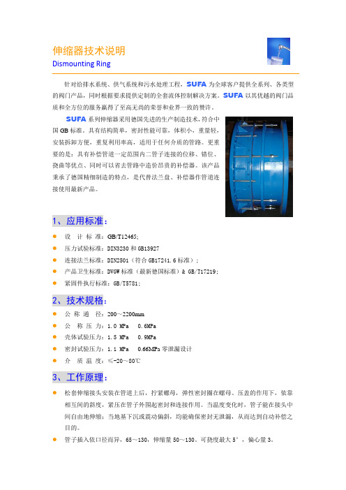
伸缩器技术说明Dismounting Ring针对给排水系统、供气系统和污水处理工程,SUFA为全球客户提供全系列、各类型的阀门产品,同时根据要求提供定制的全套流体控制解决方案。
SUFA以其优越的阀门品质和全方位的服务赢得了至高无尚的荣誉和业界一致的赞许。
SUFA系列伸缩器采用德国先进的生产制造技术,符合中国GB标准。
具有结构简单,密封性能可靠,体积小,重量轻,安装拆卸方便,重复利用率高,适用于任何介质的管路。
更重要的是:具有补偿管道一定范围内二管子连接的位移、错位、挠曲等优点、同时可以省去管路中造价昂贵的补偿器。
该产品秉承了德国精细制造的特点,是代替法兰盘、补偿器作管道连接使用最新产品。
1、应用标准:●设计标准:GB/T12465;●压力试验标准:DIN3230和GB13927●连接法兰标准:DIN2501(符合GB17241.6标准);●产品卫生标准:DVGW标准(最新德国标准)& GB/T17219;●紧固件执行标准:GB/T5781;2、技术规格:●公称通径:200~2200mm●公称压力:1.0 MPa 0.6MPa●壳体试验压力:1.5 MPa 0.9MPa●密封试验压力:1.1 MPa0.66MPa零泄漏设计●介质温度:≤-20~80℃3、工作原理:●松套伸缩接头安装在管道上后,拧紧螺母,弹性密封圈在螺母、压盖的作用下,依靠相互间的斜度,紧压在管子外围起密封和连接作用。
当温度变化时,管子能在接头中间自由地伸缩;当地基下沉或震动偏斜,均能确保密封无泄漏,从而达到自动补偿之目的。
●管子插入依口径而异,65~130,伸缩量50~130。
可挠度最大5°,偏心量3。
●主要用于闸阀、蝶阀、止回阀、球阀、截止阀等各种阀门及各种设备与管子的连接。
介质水、油、气等。
4、材质选用:●本体及压盖采用整体浇铸式结构,树酯砂铸造。
材质球墨铸铁GGG50,符合DIN1693要求,强度大于500MPa,延伸率大于10。
VSSJ-C2F-6C伸缩节使用说明书
VSSJ‐C2F‐6C型双法兰连接传力伸缩接头使用说明书铁岭市求精阀门厂二○一三年四月目 录1.主要用途2.结构特点3.执行标准4.工作原理、主要结构、外形及连接尺寸5.主要零部件材料6.保管、安装及使用7.注意事项8.通讯方式1.主要用途伸缩节是管线连接的常用且必须的附件。
本系列伸缩节主要用于介质温度≤80℃的输水管路上,安装在阀门或者其它设备的一侧,用于方便阀门或设备的拆卸和维修。
2.结构特点2.1法兰连接,结构简单,调整灵活,安装方便;2.2对于上下游管道的错位、偏角有一定的补偿作用;2.3伸缩量可根据用户的要求灵活设计,节省安装空间,降低设备成本;2.4各个零部件采用不同的材料配置即可产生多种组合,适应不同用户要求。
3.性能规范双 法 兰 伸 缩 节 性 能 规 范公称压力 0.25 0.6 1.0 1.6 2.5 4.0 MPa试验压力 强度 0.375 0.90 1.50 2.40 3.75 6.00温度常温 密封 0.300 0.75 1.25 2.00 3.00 5.00 常温工作压力(MPa)P80.250 0.60 1.00 1.60 2.50 4.00 ≤80℃ 适用介质 水、海水、油品适用温度 ≤80℃4.执行标准4.1设计制造按照GB/T 12465‐2000标准;4.2法兰连接按照GB/T 9113.1‐2000标准;4.3压力试验按照GB/T 13927‐2008标准。
5.主要结构、工作原理、外形及连接尺寸5.1主要结构:本伸缩节由法兰管、密封圈、法兰压盖、贯通螺柱、螺母、伸缩管、压盖螺柱、压盖螺母等组成。
如图1.5.2工作原理:本伸缩节一般安装在阀门(或其它设备)的上游侧。
即伸缩节的上游为管道法兰,下游为阀门。
本伸缩节的贯通螺柱分别深过管道配对法兰和阀门配对法兰的背面,通过螺母,实现上下游管道和阀门设备的对接。
需要拆卸阀门时,先把贯通螺柱无方头端(法兰管一侧)的配对法兰背后的螺母松开,再将伸缩管一侧的螺母向法兰管方向松开,然后固定贯通螺柱的方头,旋转伸缩管配对法兰背面的螺母,使法兰管端向伸缩管端移动。
双法兰限位伸缩接头-技术说明教学提纲
双法兰限位伸缩接头-
技术说明
1、B2F(VSSJA-2)型双法兰松套限位伸缩接头(外型图)
2、本厂生产的伸缩接头的工作压力为1.0MPa,设计制作均符合GB/T12465--2007。
标准。
出厂均有严格的检验手段,能满足各种运行工况在水泵校验等状况下不会产生纵向位移。
法兰符合GB/T9115-2000标准。
3、产品特点:
(1)本次合同生产伸缩接头:本体,短管、螺柱、采用Q235,;密封圈采用丁晴橡胶;压盖、螺母等均采用Q235材质。
(2)由于同一类型的全部伸缩接头均为本厂生产,毛坯统一订货,同一型号伸缩接头的零部件,易损件均能互换。
伸缩接头醒目处均注明闸门型号、口径、工作压力。
4、主要产品结构尺寸表:
限位伸缩接头主要由松套伸缩接头和限位短管等构件组成。
它能防止管道因超量位移导致补偿接头的泄漏或损坏。
主要用于在允许位移范围内吸收轴向位移和承受压力推力的管道松套连接。
1—本体 2—密封圈 3—压盘 4—限位螺杆 5—螺母 6—限位短管 7—螺柱
双法兰松套限位伸缩接头
尺寸连接表
公称通径管子外径外形尺寸
伸缩量
法兰连接尺寸Dw L L1
0.6MPa 1.0MPa
D D1 n-d。
D D1 n-d。
65 76
340 105 50
160 130 4-¢14 185 145 4-¢18 80 89 190 150 4-¢18 200 160 8-¢18。
什么是伸缩器 伸缩器安装 伸缩器使用范围
什么是伸缩器伸缩器安装伸缩器使用范围伸缩器也称伸缩节、膨胀节、补偿器。
伸缩器在一定范围内可轴向伸缩,也能在一定的角度内克服管道对接不同轴向而产生的偏移,能极大的方便阀门管道的安装与拆卸,在管道允许伸缩量中可以自由伸缩,一旦越过其最大伸缩量就起到限位的作用,确保管道的安全运行。
伸缩器在一定范围内可轴向伸缩,也能在一定的角度内克服管道对接不同轴向而产生的偏移,能极大的方便阀门管道的安装与拆卸,在管道允许伸缩量中可以自由伸缩,一旦越过其最大伸缩量就起到限位,确保管道的安全运行。
主要为保障管道安全运行,具有以下作用:补偿吸收管道轴向、横向、角向热变形;吸收设备振动,减少设备振动对管道的影响;吸收地震、地陷对管道的变形量。
1. 伸缩器为各种给排水管道、水塔、水泵、水表、阀门的安装拆换提供了极大方便,给长距离管路因温差伸缩起到了很好的调节作用。
2. 伸缩器内管材分为铸铁( HT )、镀锌( DX )和钢制( SF )三种。
工作压力分 PN6 、 PN10 、PN16 三种。
3. 安装前须松开压盘螺栓,将该产品拉至安装长度,然后用对角法拧紧,切勿压偏,如架空使用,两端须安装相应的固定支架。
4. 法兰连接采用 GB4216.3 - 4126.5 标准。
5. 如选用其它规格可另行生产。
伸缩器连接方式:法兰连接、焊接两种,直埋式伸缩器(非地沟、设井安装时)一般采用焊接。
伸缩器安装注意事项:1、伸缩器在安装前应先检查其型号、规格及管道配置情况,必须符合设计要求。
2、对带内套筒的伸缩器应注意使内套筒子的方向与介质流动方向一致,铰链型伸缩器的铰链转动平面应与位移转动平面一致。
3、需要进行“冷紧”的伸缩器,预变形所用的辅助构件应在管路安装完毕后方可拆除。
4、严禁用伸缩器变形的方法来调整管道的安装超差,以免影响伸缩器的正常功能、降低使用寿命及增加管系、设备、支承构件的载荷。
5、安装过程中,不允许焊渣飞溅到波壳表面,不允许波壳受到其它机械损伤。
消防伸缩节安装工艺

消防伸缩节安装工艺以下是我写的关于消防伸缩节安装工艺,仅供参考:何为消防伸缩节消防伸缩节又称管道伸缩器,管道伸缩接头。
消防伸缩节是泵、阀门,管道等等设备连接部署与管道连接的新产品,通过全螺栓把它们连接成一个整体,并有一定的位移量,这样在安装和维修的时候就可以凭据现场安装尺寸进行测试,在工作时,可以把轴向推力传送到整个管道系统。
这样不仅能提高工作效率,而切对泵、阀们等管道设备连接起到保护作用。
消防伸缩节分类BF型单法兰限位伸缩节、AY型压盖式伸缩节、B2F型双法兰限位伸缩节、AF型法兰式松套伸缩节、CF单法兰传力接头、BY型压盖式限位伸缩节、C2F双法兰传力接头、CC2F型可拆式双法兰传力接头等。
消防伸缩节安装规范消防伸缩节在五金管道中所使用的时候主要为长距离的管路因为温度差距所引起的伸缩提供了较大的方便,该产品由于具有良好的综合性能,所以常用于阀门,消防,化工等管道系统中,消防伸缩节在安装的时候首先需要注意以下几点:1、管道缩节在安装前应先检查其型号、规格及管道配置情况,必须符合设计要求。
2、对带内套筒的伸缩器应注意使内套筒子的方向与介质流动方向一致,铰链型伸缩器的铰链转动平面应与位移转动平面一致。
3、需要进行“冷紧”的伸缩器,预变形所用的辅助构件应在管路安装完毕后方可拆除。
4、严禁用伸缩器变形的方法来调整管道的安装超差,以免影响伸缩器的正常功能、降低使用寿命及增加管系、设备、支承构件的载荷。
5、消防伸缩节在安装的过程中,不允许焊渣飞溅到波壳表面,不允许波壳受到其它机械损伤。
6、消防伸缩节在管系的安装完毕之后,应该尽快拆除波伸缩器上用作安装运输的黄色辅助定位构件及紧固件,并按设计要求将限位装置调到规定位置,使管系在环境条件下有充分的补偿能力。
7、消防伸缩节所有活动元件不得被外部构件卡死或限制其活动范围,应保证各活动部位的正常动作。
8、水压试验时,应对装有伸缩器管路端部的次固定管架进行加固,使管路不发生移动或转动。
重卡用FK2型伸缩硬杆变速操纵系统安装使用说明书

FK2型变速操纵器产品说明书上海惟译汽配制造有限公司FK2型变速操纵器性能介绍目录一、技术背景 (1)二、技术特性 (1)A、伸缩硬杆直接传动手动变速操纵系统 (1)B、换力器分段传动手动变速操纵系统 (3)三、特性介绍 (4)1、操纵器特性介绍 (4)2、伸缩主杆&副杆特性介绍 (5)3、换力器特性介绍 (6)四、安装 (7)1、驾驶室端安装 (7)2、变速箱端安装 (9)3、在驾驶室倾翻状态下操纵器与伸缩杆连接 (16)五、调试 (19)1、操纵器部分免调试 (19)2、变速器部分 (19)3、伸缩杆部分 (20)六、使用及维护 (21)1、驾驶室的翻转 (21)2、各球节维护 (22)3、变速操纵机构维护 (23)4、部件维修及置换 (24)七、常见故障&排除方法 (25)1、操纵器窜动&自然脱档 (25)2、伸缩铝管变形弯曲 (26)3、中间换力器托座变形断裂 (27)4、换挡(前后)空行程状态 (27)5、选档(左右)行程偏大 (28)一、技术背景重型汽车在不断的改进过程中,传统的手排硬杆变速操纵系统改变为软轴传动。
由于传统的硬杆操纵器无法实现与驾驶室整体倾翻影响到驾驶室的密封性能,无法解决室外粉尘的入侵。
北方奔驰在21世纪初在国内首先采用伸缩硬杆解决了操纵器与驾驶室整体倾翻的技术问题。
到目前重型汽车驾驶室已采用四气囊避震装置,提高驾乘人员的舒适度。
驾驶室避震性能的提高意味着驾驶室与底盘的非对称运动增强,由此造成车辆行驶不良路面时,造成操纵杆急剧晃动变速器自然脱档,凡具有优良避震性能的驾驶室就无法配置硬杆变速操纵系统,淘汰硬杆改为手排软轴操纵系统,软轴操纵解除了硬杆操纵存在的问题,但是长期运行中软轴操纵受到环境影响而有如下几个问题:A、变速操纵的耗力软轴大于硬杆,尤其是使用半年以上,传动效率低、伴随着耗力增大。
B、受到柴油机排气系统温度的侵蚀,严重影响软轴的使用寿命。
伸缩器

伸缩器(补偿器)安装指导由于输送介质温度的高低或周围环境的影响,管道在安装与运转时温度很高,必然引起管道长度和直径相应的变化,当温度差产生额热应力超过管材的允许压力时,使管子处于随时有损坏或危险状态之下,因此必须在管路上安装一定的装置来使管子有伸缩的余地,这就是为热胀冷缩用的伸缩器。
方形伸缩器安装注意事项:1、方形伸缩器组对时,应在平台上或平地上拼接。
2、垂直安装时,如输送介质为液体,应在伸缩器的最低点装疏水装置。
伸缩器两侧的第一支架宜设在距伸缩器弯头的弯曲起点0.5~1m处,支架的活动支架,不得设导向支架。
3、安装伸缩器为了减少热应力和提高热补偿能力,必须对伸缩器进行预拉伸,输送热介质的管道需冷拉,输送冷介质需冷压。
管道的预拉或预压应在两个固定支架之间的管道安装完毕并与固定支架连接牢固以后进行,预拉伸或预压缩的焊口离开伸缩器的起弯点应大于2mm,并应将伸缩器两臂同时拉伸或压缩。
4、管道支段设置伸缩器的最大距离。
5、方形伸缩器的预拉伸。
方形伸缩器安装前应进行预拉伸。
拉伸的方法,一种是用千斤顶将方形伸缩器顶开,另一种是常用的拉管器法。
在拉伸前,先将两端的固定支架焊牢,伸缩器两端的直管与连接管的末端之间应预留一定的间隙,其间隙值应等于设计补偿量的1/4。
然后用拉管器安装在两个待焊的接口上,收紧拉管器螺栓,拉开伸缩器直到管子接口对齐,并把它点焊好方可拆除拉伸器。
波形伸缩器:波形伸缩器因其强度较弱,补偿能力小,轴向推力大,适用于管径大于150mm以上及压力低于0.6MPa的管道。
波形伸缩器由钢板制成,其外形如下:波形伸缩器安装注意事项:1、波形伸缩器安装前应检查其各部尺寸是否符合要求,波形伸缩器表面不得有裂纹、凹凸、轧痕等缺陷。
并按设计规定压力,进行水压试验,合格后方可安装。
2、安装时,应注意伸缩器的方向。
伸缩器内的衬套外壳焊接的一端,应朝向坡度的上方,以防冷凝水大量流到波形皱折的凹槽中。
3、伸缩器的拉伸和压缩,应在平地上分次逐渐进行,拉伸或压缩应按照施工图规定数值进行,在待接管道上留出伸缩器的位置,再用拉管器将伸缩器拉长或缩短后,与管子连接。
伸缩器系列技术说明书

伸缩器系列VSSJA平面法兰式送套伸缩节头单法兰限位伸缩接头VSSJA-1双法兰限位伸缩节头VSSJA-2VSSJAF双法兰传力伸缩接头VSSJAFG单法兰传力伸缩接头SSJB压盖式伸缩接头波纹补偿器SQ4G双盘伸缩器GJQ橡胶伸缩器型号编制说明工作原理及用途松套伸缩接头安装在管道上以后,拧紧螺母,弹性密封圈在螺母、压盖的压力下,依靠相互间的斜度,紧压在管子外围起密封和链接作用。
当温度变化时,管子能在接头中间自由地伸缩,当地基下沉,船舶振动偏斜,它均能确保密封无渗漏,从而达到自动补偿的目的。
VSSJA系列VSSJA平面法兰式送套伸缩节头VSSJA结构图单法兰限位伸缩接头VSSJA-1VSSJA-1结构图双法兰限位伸缩节头VSSJA-2VSSJA-2结构图用途VSSJA型可广泛与蝶阀、闸阀、止回阀、截止阀等配套使用,可降低工程费用能有效解决阀门装卸困难。
主要用于管道与阀门链接,带有限位螺栓,可防止管道在外部作用力及热胀冷缩引起的内部作用较大时,拉脱伸缩接头,造成不必要的管道泄漏事故。
主要部件表主要结构尺寸传力伸缩接头作用及用途该接头能把因自然条件或工作条件造成的管道轴向推力和拉应力,通过螺栓从管道的这一端传递到整个管道,使应力分撒,避免造成管道设备的损坏。
VSSJAFG单法兰传力伸缩接头VSSJAFG结构图VSSJAF双法兰传力伸缩接头VSSJAF结构图主要部件表双盘伸缩器产品性能及用途该伸缩接头采用国标制造,重量轻,补偿量大,结构简单新一代伸缩器,它能有效的补偿管道因热胀冷缩造成的管道位移和折扣。
并能和各种阀门配套使用,使阀门装卸更便捷,使管线运行更安全、可靠,也可根据需要增加限位或防拉脱螺栓。
双盘伸缩器SQ4GSQ4G结构图主要部件表主要结构尺寸橡胶伸缩器GJQ型可曲绕橡胶接头又叫减震器、软接头等。
该产品是金属管道的柔性联接器,由内胶层、棉纶帘子布增强、外胶层复合的橡胶球体和松套金属法兰组成。
杜弗利自动球型阀门BV2-F1系列说明说明书

D 4.250 4.620 5.000 6.500 7.000 7.500 8.000 9.000
E 7.720 7.720 9.550 11.690 11.690 15.910 20.550 20.550
D
A
ACT. SR2 SR3 SR4 SR4 SR6 SR7 SR8 SR9
Series BV2-F1 ball valves offer ANSI 150# flanged ends for easy installation. 1/2˝ through 4˝ sizes are standard for great flow rates with minimal pressure drop. The valve features a blowout-proof stem for added safety, reinforced TFE seats and seals for longer life, and a 316SS (ASTM A351 GR CF8M) ball for better performance. Actuators are direct mounted, creating a compact assembly for tight spaces. Double o-ring stem seals assure leak-free operation. The BV2-F1 Series is an economical automated valve package with either an electric or pneumatic actuator. Electrically actuated models are weatherproof, NEMA 4, powered by standard 115 VAC supply, and are available in either two-position or proportional control. Two-position actuators use the 115 VAC input to drive the valve open or closed, while the modulating actuator accepts a 4 to 20 mA input for infinite valve positioning. Actuator features thermal overload protection and a permanently lubricated gear train. The pneumatic double acting actuator uses an air supply to drive the valve open and closed. The actuator has two supply ports with one driving the valve open and the other driving the valve closed. Spring return pneumatic actuators use the air supply to open the valve and internally loaded springs return the valve to the closed position. Also available is the SV3 solenoid valve to electrically switch the air supply pressure between the air supply ports for opening and closing the valve. Actuators are constructed of anodized and epoxy coated aluminum for years of corrosion free service.
双法兰限位伸缩器在管道上的作用
双法兰限位伸缩器在管道上的作用
双法兰限位伸缩器是一种用于管道系统的装置,主要作用是实现管道系统的伸缩和限位。
具体作用包括:
1. 起缓冲作用:双法兰限位伸缩器可以在管道系统中起到缓冲作用,吸收由于管道的热胀冷缩或振动引起的应力和变形。
它可以灵活地伸缩,避免了管道系统的堵塞、断裂等问题。
2. 限位作用:双法兰限位伸缩器可以限制管道系统的伸缩范围,防止过度伸缩导致管道的破裂和泄漏。
它可以根据管道系统的需要进行调整,保证管道在合适的伸缩范围内工作。
3. 减少振动和噪音:双法兰限位伸缩器可以减少管道系统中的振动和噪音,提高系统的稳定性和工作效率。
它可以吸收管道系统中的冲击和震动,并将其转化为弹性形变,从而减轻系统的振动和噪音。
4. 调节安装误差:双法兰限位伸缩器可以用来调节管道系统的安装误差。
在安装管道系统时,往往难以保证各个管道的精确对齐,而限位伸缩器可以通过其伸缩功能,将管道的位置进行微调,使之达到理想的安装效果。
总之,双法兰限位伸缩器在管道上的作用主要包括实现管道的伸缩和限位、起缓冲作用、减少振动和噪音以及调节安装误差等。
它可以提高管道系统的稳定性、耐用性和安全性,保证管道的正常运行。
手动液压伸缩器操作规程

手动液压伸缩器操作规程一、用途和结构特点1.用途手动液压伸缩器主要用于安装在计量系统或需要进行长度调整的管路中,补偿系统或管路中因更换流量计或管道组合件等产生的长度变化,满足系统管路的正常运行。
手动液压伸缩器也适用于介质较脏需要经常清洗的工况管道。
2、结构特点及示意图手动液压伸缩器两端与管道中采用法兰连接,该伸缩器使管道的装拆、调整非常方便,其最大伸缩距离为100mm+20mm,也可根据用户伸缩长度的需求进行特殊设计、订货。
详细结构见下面示意图:图一:手动液压伸缩器结构示意图件1—伸缩器内筒;件2—调整丝杆;件3—螺母;件4—防尘圈;件5—伸缩器外筒;件6—组合密封;件7—油缸;件8—不锈钢输油管;件9—手动液压站;图二:手动液压伸缩器液压站实物图三、操作说明:1. 手动液压伸缩器按第二项的技术要求安装、试验合格,并确定与手动液压伸缩器外筒端法兰(图一左端)完全固定不会移动,伸缩器内筒端(图一右端)连接的管道具有一定距离的移动位置,可进行伸出、缩进测试:a)松开4 只(件2)调节丝杆的螺母(件3),每根调整丝杆的4 个螺母按要求进行调整:第1、4 个向外反向松开、第2、3 个向内反向松开,使每个螺母与对应的法兰面有一定间隔距离(应大于需要伸缩的长度)。
b)把红色圆球手柄向前轻推到位,用加力杆套入手动液压泵操作杆,上、下压动加力杆,伸缩器内筒匀速向前伸出。
把红色圆球手柄向后轻拉到反向位置,用加力杆套入手动液压泵操作杆,上、下压动加力杆,伸缩器内筒匀速向后缩进。
c)手动液压伸缩器内筒法兰面到达指定的长度位置后,将红色圆球手柄轻推到中间空档位置,这时手动泵如果继续上、下压动加力杆,液压站也不再向油缸输出压力。
把每根调整丝杆的4 个螺母、对称用力锁紧,保证手动液压伸缩器的内筒和外筒在受压工作状态下不产生位移。
整个管路系统可以进行工作。
d)在液压站通过手动泵向油缸输送压力,应注意压力表的压力变化情况,正常情况下,压力表最大工作表压不应超过16MPa,如最大工作表压超过16MPa,必须及时停止操作,检查手动液压伸缩器内筒有无阻涉、卡阻现象、伸缩长度是否到位等,直至找到产生压力超高的原因,否则不得继续使用。
Festo MS2-LF-.-B 滤波器操作手册说明书
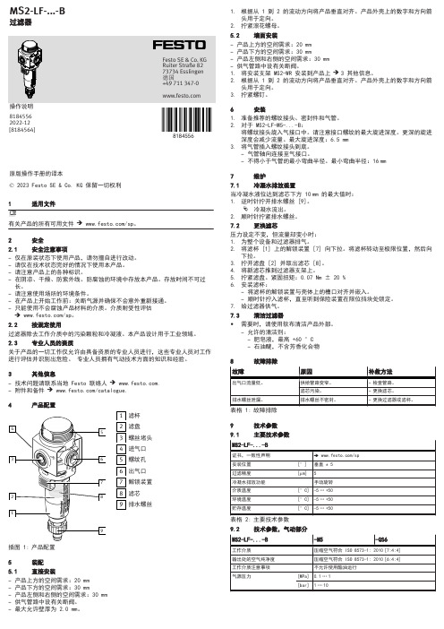
81845561适用文件2安全2.1安全注意事项–仅在原装状态下使用产品,请勿擅自进行改动。
–请仅在技术状态完好的情况下使用本产品。
–请注意产品上的各种标识。
–在阴凉、干燥、防紫外线、防腐蚀的环境中存放本产品。
存放时间不可过长。
–请注意使用场所的环境条件。
–在产品上开始工作前:关断气源并确保不会意外重新接通。
–只能使用不会腐蚀产品材料的介质。
介质耐受性评估è /sp。
2.2按规定使用过滤器除去工作介质中的污染颗粒和冷凝液。
本产品设计用于工业领域。
2.3专业人员的资质关于产品的一切工作仅允许由具备资质的专业人员进行,这些专业人员对工作进行评估并识别出危险。
专业人员拥有气动技术方面的知识和经验。
3其他信息–技术问题请联系当地 Festo 联络人 è .–附件和备件 è /catalogue.4产品配置插图 1:产品配置滤杯滤盘螺丝堵头进气口螺纹孔出气口解锁装置滤芯排水螺丝5装配5.1直接安装–产品上方的空间需求:20 mm –产品下方的空间需求:30 mm–产品左侧和右侧的空间需求:30 mm –供气管路中设有关断阀。
–最大允许壁厚为 2.0 mm。
1.根据从 1 到 2 的流动方向将产品垂直对齐。
产品外壳上的数字和方向箭头用于定向。
2.拧紧滚花螺母。
5.2墙面安装–产品上方的空间需求:20 mm –产品下方的空间需求:30 mm–产品左侧和右侧的空间需求:30 mm –供气管路中设有关断阀。
1.将安装支架 MS2-WR 安装到产品上 è 3 其他信息。
2.根据从 1 到 2 的流动方向将产品垂直对齐。
产品外壳上的数字和方向箭头用于定向。
3.拧紧螺钉。
6安装1.准备推荐的螺纹接头、密封件和气管。
2.对于 MS2-LF-M5-...-B:将螺纹接头旋入气接口中。
请注意接口螺纹的最大旋进深度。
更深的旋进深度会减少流量。
最大旋进深度:6.5 mm 3.将气管插入螺纹接头到底。
伸缩接头技术参数

双法兰伸缩接头使用说明及技术说明书巩义市昌盛供水材料有限公司双法兰限位伸缩接头说明一、主要技术参数1.型号:VSSJA-2/B2F2.公称压力:0.6 Mpa 、1.0 Mpa 、1.6Mpa 、2.5Mpa3.壳体试验压力:0.9Mpa 、1.5Mpa 、2.4Mpa、3.75Mpa(1.5倍公称压力)4.密封试验压力:0.66Mpa 、1.1Mpa 、1.76Mpa、2.75Mpa(1.1倍公称压力)5.工作温度:-20℃~80℃6.适用介质:水、污水7.漏失率:0二、产品执行标准产品设计执行GB/T12465-2007《管路补偿接头》法兰连接尺寸执行GB 2555《一般用途法兰连接尺寸》压力试验执行GB/T13927-2008《工业阀门压力试验》包装、运输以及标志符合GB12220、GB12252的规定三、产品结构性能特点1.结构简单、零部件少、重量轻。
2.安装方便,能补偿管线法兰的位置及角度误差。
3.限位伸缩接头带限位及防拉脱装置。
4.该产品与阀门等的配套使用,给阀门的维修带来极大的方便。
5.伸缩接头采用标准化设计,同类零部件具有绝对互换性。
6.使用寿命长,整体首次无故障工作时间不少于50000h。
四、主要技术描述1.伸缩接头主要由本体、伸缩套管、压盖、密封圈、螺栓组成。
伸缩体、伸缩套管、压盖采用Q235制造而成,密封圈采用丁腈橡胶密封,具有良好的水密性和气密性。
2.伸缩接头和阀门等配套使用,通过自身两法兰面之间的轴向伸缩和径向角位移,来补偿管线法兰的位置及角度误差,消除因管道温差造成的管道内应力,给管道的安装和维修带来极大的方便。
3.伸缩接头在出厂时的结构为安装长度,用于连接阀门时,可把伸缩接头调到所需长度,但不得超出伸缩量范围。
如用于补偿管道因温差引起的位移,安装时必需在常温下调整至安装长度;伸缩接头可在管线任意位置上安装,但用于连接阀门时要位于阀后;较长或较重的管道要在伸缩器附近设置活动支座,保证伸缩接头运行正常;安装后要及时将伸缩器压盖螺栓紧固,注意松紧程度,要根据管道工作压力调节,太紧或太松会影响密封效果和伸缩性,灵活性,同时要及时将限位螺栓固定好,防止使用时拉脱。
阿瓦克·F-PPP2可移动专业2浴池拉力器使用指南说明书

Manuals+— User Manuals Simplified.Aqua Creek F-PPP2 Portable Pro 2 Pool Lift Instructions Home » Aqua Creek » Aqua Creek F-PPP2 Portable Pro 2 Pool Lift InstructionsAqua Creek F-PPP2 Portable Pro 2 Pool LiftContents1 MANDATORY2 READ CAREFULL Y3 Portable Pro Pool 2 Components4 Portable Pro Pool 2 Assembly Instructions (Weight Plates)5 Portable Pro Pool 2 Assembly Instructions (Sand Ballast)6 Portable Pro Pool 2 Assembly Instructions7 Basic Troubleshooting8 Proper Care of Pool & Spa Lifts9 Portable Pro Pool 2 Lift Parts List10 Portable Pro Pool 2 Cart Parts List11 PORTABLE PRO POOL 2 LIFT12 Customers Support13 Documents / Resources14 Related PostsMANDATORYLEAVE THIS MANUAL WITH OWNERRead and follow all instructions.Lift safety can only be ensured if the lift is installed and operated according to these instructions.FOR SAFETY REASONSNEVER swim aloneNEVER use the lift with a dry poolNEVER apply direct water pressure to the electronicsNEVER permit children to play on or around the liftDO NOT allow children to use the lift without adult supervisionREAD CAREFULLYCheck entire box and all packing materials for parts. Before beginning assembly, read the instructions and identify parts using the figures and parts listed in this document.It is critical that all parts be carefully inspected prior to installation. If any damage occurred in transit, Aqua Creek Products, LLC must be notified within three days of receipt of unit.Proper installation cannot be overstressed, as an improper installation voids Aqua Creek’s warranty and mayaffect the safety of the user.Portable Pro Pool 2 Components1. PORTABLE PRO POOL 2 LIFT2. LINAK BATTERY CHARGERand set aside.2. Begin stacking the eleven (11) supplied weight plates on the portable platform. To ensure proper alignment,slide the hood over the stack every three (3) or four (4) plates. Continue this until all eleven (11) weight plates are in place.3. Using a 7 /16″ wrench, slide the hood over the stack of weight plates and attach to the platform using the five(S) supplied 1/4″ nylock nuts and flat washers. NOTE: Be sure to use silicone to seal the flange before bolting together.+Portable Pro Pool 2 Assembly Instructions (Sand Ballast)1. Fill the ballast tank with sand (not included) as shown below. Gently shake or tap the tank sides periodically tohelp level the sand. Alternate between fill ports to make sure sand is evenly distributed (use a large funnel to help in this step).2. Once all the sand has been poured into the tank, return the caps to the top of the tank and attach them with thescrews.3. With the counter weight now in place, roll the lift to the desired location on the pool deck.Portable Pro Pool 2 Assembly Instructions4. Attach seat belt to the seat as shown in diagram to the right.5. Place the battery on the charger and bring to a full charge.6. Apply dielectric grease on the metal tabs of the battery and the control box on the lift.7. Mount the battery onto the control box on the lift and snap the battery into place. Listen for a ‘click’ when thebattery is installed properly. There should be no gap between the battery and control box. See FIGURE 1.NOTE: To extend battery life, always store battery on the charger when the lift is not in service.Basic TroubleshootingProblem: The lift won’t moveSolution:1. Make sure the battery is properly seated:You should hear a click when the battery is properly seated on the control box or charger.NOT Properly Attached:Note: the white bracket is in front of the silver clip, which will not allow for an electrical connectionProperly Attached:Note: the white bracket is behind the silver clip, holding it securely to allow for an electrical connection2. Make sure the cords are properly plugged in:NOT Properly Inserted:The cord plug is flush with or sticking out of the outletThe cord plug is recessed into the outletCheck the ends of the cords for corrosion or damage. The cord plugs should be recessed into the outlet. You should feel them pop into place when they are correctly inserted.3. Check the contact points:Make sure the contact points of the control box and the battery are not damaged or corroded. If there is corrosion clean with Scotch-Brite™ pad. Put some dielectric grease on the contact points before reattaching the battery.4. Make sure the battery is fully charged:The Charger is ON when the green light is glowingThe Battery is CHARG- 1 NG when the orange light is glowingWhen the Battery is charged the orange light will stop glowingProblem: The lift stopped moving over the water and is stuck.Solution:1. Press the emergency buttonUse a pen or pencil tip and stick it into the emergency button on the front of the control box to retract the lift.Note: the lift will not retract if the battery is not fully charged or if the control box is not working. The emergency button only overrides the remote handset.Proper Care of Pool & Spa LiftsPROCEDURE BEFORE EACH USEDAILYWEEKLYMONTHLYCheck battery level indicator on control box✔Run the lift through a complete test cycle (fully ex- tend actuator) to verify it is functioning properly✔Wash lift with fresh water and dry with clean, soft, non-abrasive cloth✔Recharge battery✔Visually inspect lift for damage, corrosion, and loose ormissing hardware✔Check all contact points for damage and/or corrosion✔Repair, clean and apply dielectric grease to all contact points✔Thoroughly clean lift frame and apply a liberal coat of car waxto maintain the lift’s finish✔Check all Warning and Cautionary labels to make sure they are not faded or worn. Replace as needed.✔PROPER CARE NOTESUse only fresh water to wash your lift. Do not wash with pool water.Use only clean, soft, non-abrasive cloths on your lift.Do not store lift in pump room or near chemicals.Do not allow children to play on or around this lift.When cleaning the lift, do not spray water directly on control box or battery.The lift may need to be bonded according to local code requirements.If the lift is not used for extended periods, remove the battery from the lift and store it on the wall charger to maintain the batteries charge. The charger should be plugged in and in a climate controlled area.STAIN REMOVAL TIPS:To remove stubborn stains from finish, spray affected area with mild dish soap, rub briskly with a 3M Scotch Brite™ pad. Use white epoxy paint to touch up the finish. Apply wax to protect when dry.Portable Pro Pool 2 Lift Parts ListITEM•QTY PART•DESCRIPTION11PF2-100-02BASE WELDMENT21PF2-200-03MAIN FRAME ASSEM- BLY31PF2-300-03CHAIR CRADLE AS- SEMBLY 41PF2-400-04CONTROL ARM51PF2-500-00BRACKET ASSEMBLY 61340665-00LINAK 400MM PULL ACTUATOR 71F-0904CA-A CHAIR ASSEMBLY81F-FRB-03FOOTREST ASSEMBLY91MBJ2-01LINAK CONTROL BRACKET 101CBJ2-U033-00LINAK CONTROL BOX111BAJ1-U026-0024V LINAK BATTERY121MS LPCS CONTROL BOX SCREW131WF10#10 FLAT WASHER142BSH 10 X 3/810-24 X 3/8 SHCS151BB1/4X1/21/4-20 X 1/2 BHSCS161WF 1/41/4 FLAT WASHER171WL 1/41/4 LOCK WASHER181BH 5/16 X 4 1 /25/16-18 X 41/2 HCS195WF 5/165/16 FLAT WASHER204NN 5/165/16-18 NYLOCK NUT211BS 3/8 X 9/163/8 X 9/16 SHOULDER BOLT221BS 3/8 X 1 3/418-83/8 X 1 3/4 SHOUL- DER BOLT231BS 3/8 X 2 18-83/8 X 2 SHOULDER BOLT242BC 3/8 X 33/8-16 X 3 FHSCS252WF3/83/8 FLAT WASHER262NN 3/83/8 NYLOCK NUT271BH 5/8 X 5 7/818-85/8 X 5 7/8 HCS282WFS/85/8 FLAT WASHER291NN 5/85/8 NYLOCK NUT301NNJ 11″ NYLOCK JAM311BRB EP0608033/8 X 1/2 X 3/16 SLEEVE BUSHING 322BRB SS-1216-61/2 X 3/8 X 3/8 BRONZE SLEEVE331F-UBC BATTERY COVER Portable Pro Pool 2 Cart Parts ListItem•QTY PART#DESCRIPTION11PP2-100WM-00PORTABLE PRO POOL 2 CARTWELDMENT22PP2-109-00WHEEL SPACER31PP2-110-00AXLE SHAFT42 5.00008.459.2.SSRB WHEEL, RUBBER, PERFORMA, SS BEARING512NF100SA4″SS CASTER ASSEMBLY64BB 5/16 X 3/4BOLT, 316 SS, 5/16-18 X 3/4 BHSCS74WF 5/16WASHER, FLAT, 5/16, 316 SS84NN 5/16NUT, 316 SS, NYLOCK, 5/16-1892LOCK COLLAR 3/4 SS LOCK COLLAR, 3/4, SS, SINGLE SPLIT*1011WP-60WEIGHT PLATE, CONCRETE, 2″x 18″ x 18″111A-985B COVER ASSEMBLY125WFE 1/4WASHER, FENDER, 316 SS, 1/4 X 1135NN 1/4NUT, 316 SS, NYLOCK, 1/4-20AQUA CREEK PRODUCTS, LLC LIMITED FIVE (5) YEAR WARRANTY:PORTABLE PRO POOL 2 LIFT(ITEM #’s F-PPP2, F-PPP2-T, F-PPP2-G, F-PPP2-C, F-PPP2S, F-PPP2S-T, F-PPP2S-G, F-PPP2S-C)Aqua Creek Products, LLC (a .k.a. Aqua Creek) warrants to the original end user purchaser that products manufactured by Aqua Creek, when properly installed in accordance with assembly and installation instructions, and properly used and maintained, shallbe free from defects in material and workmanship for a period of five (5) years from the date of original purchase, provided that Aqua Creek receives prompt notice in writing of any defect or failure and satisfactory proof thereof, with the following exception(s):Exceptions:All electrical components, including the linear actuator shall have the following warranty period: Year 1-2: 100% CoverageYear 3: 60% Coverage (Customer is responsible for 40% of replacement cost)Year 4: 50% Coverage (Customer is responsible for 50% of replacement cost)Year 5: 40% Coverage (Customer is responsible for 60% of replacement cost)Hydraulic actuators and mesh slings shall have a warranty period of one (1) year from the date of original purchase.Powder coat finish scratches, scrapes, corrosion, or dents from customers normal use, negligence, or abuse This warranty specifically excludes reimbursement for labor to remove, repair, or install the product and any shipping charges. These warranties do not cover any damages due to accident, force majeure, act of nature,misuse, abuse, negligence or failure to properly maintain any products, or normal wear and tear from day to day operations. In the event that any products are altered, repaired, or improperly installed or improperly used by anyone without the prior written approval by Aqua Creek, all warranties are void. IMPORTANT: AMOUNT OF WEIGHT PLACED ON LIFT SHALL NOT EXCEED THE RATED LIFTING CAPACITY FOR THE LIFT. NEVER OPERATE THE LIFT UNDER LOAD IN A DRY POOL (WITH NO WATER IN THE POOL). It is the responsibility of the lift owner to verify the weight of the patron for warranty claim purposes and to ensure that the lift is not overloaded. Non-payment for product to Aqua Creek may void warranty.To initiate a warranty claim, the owner of an Aqua Creek product must provide the place of purchase, in writing, with a full description of the product, its serial number, the dates of purchase and installation, and the exact nature of the defect. Within thirty (30) days after receipt of a written warranty claim by Aqua Creek, and barring any unforeseen delays, the place of purchase will be notified of Aqua Creek’s decision regarding the claim.If requested by Aqua Creek, any defective product must be returned, freight prepaid by customer, to Aqua Creek’s designated factory location or duly appointed distributor for inspection and/or repair. Aqua Creek will, at its option, repair or replace the failed or defective item, and deliver the repaired product or replacement to the customer. All freight charges are the responsibility of the customer. Products returned to Aqua Creek for which Aqua Creek provides replacement under this limited warranty shall become the property of Aqua Creek. A new warranty period shall NOT be established for the repaired or replaced products. Such products shall remain under warranty only for the remainder of the original warranty period on the original products purchased.This written limited warranty constitutes the final, complete and exclusive statement of warranty terms. No person or organization is authorized to make any other specific or implied warranties or representations on behalf of Aqua Creek.THE WARRANTIES SET FORTH HEREIN ARE IN LIEU OF ALL OTHER WARRANTIES, EXPRESSED OR IMPLIED, WHICH ARE HEREBY DISCLAIMED AND EXCLUDED, INCLUDING WITHOUT LIMITATION ANY WARRANTY OF MERCHANTABILITY OR FITNESS FOR A PARTICULAR PURPOSE OR USE.THE SOLE AND EXCLUSIVE REMEDIES FOR BREACH OF ANY AND ALL WARRANTIES WITH RESPECT TO THE PRODUCTS SHALL BE LIMITED TO REPAIR OR REPLACEMENT AT AQUA CREEK’S DESIGNATED FACTORY LOCATION, OR DULY APPOINTED DISTRIBUTOR, OR IN PLACE AT AQUA CREEK’S OPTION. IN NO EVENT SHALL AQUA CREEK’S LIABILITY EXCEED THE ENTIRE AMOUNT PAID TO AQUA CREEK BY THE ORIGINAL PURCHASER FOR THE FAILED OR DEFECTIVE PRODUCT.IN NO EVENT SHALL AQUA CREEK PRODUCTS, LLC BE LIABLE FOR ANY INCIDENTAL, CONSEQUENTIAL, SPECIAL, INDIRECT, PUNITIVE OR EXEMPLARY DAMAGES OR LOST PROFITS FROM ANY BREACH OF THIS LIMITED WARRANTY OR OTHERWISE.THIS WARRANTY GIVES YOU SPECIFIC LEGAL RIGHTS AND YOU MAY ALSO HAVE OTHER RIGHTS, WHICH MAY VARY FROM STATE TO STATE. SOME STATES DO NOT ALLOW THE EXCLUSION OR LIMITATION OF INCIDENTAL, SPECIAL OR CONSEQUENTIAL DAMAGES, SO SOME OF THE ABOVE LIMITATIONS OR EXCLUSIONS MAY NOT APPLY TO YOU.Customers SupportAqua Creek Products, LLC9889 Garrymore LaneMissoula, MT 59808Toll Free: (888) 687-3552Local/lntnl: (406) 549-0769Documents / ResourcesAqua Creek F-PPP2 Portable Pro 2 Pool Lift [pdf] InstructionsF-PPP2 Portable Pro 2 Pool Lift, F-PPP2, Portable Pro 2 Pool Lift, 2 Pool Lift Manuals+,。
2 - 24 BF系列蝶阀操作与维护手册说明书

2" - 24"BF SeriesButter f ly ValvesOperation andMaintenance ManualJob Name: ____________________________Contractor: ___________________________Date: ________________________________BF Series Butter f ly Valv esSAFETY MESSAGESAll safety messages in the instructions are flagged with an exclamation symbol and the word “w arning”. These messages indicate procedures that must be followed exactly to avoid equipment damage, physical injury, or death. Safety labels on the product indicate hazards that can cause equipment damage, physical injury, or death.Personnel involved in the installation or maintenance of valves should be constantly alert to potentialemission of pipeline material and take appropriate safety precautions. Always wear suitable protection when dealing with hazardous pipeline materials.PARTSOrder parts directly from Henry Pratt Company through your local distributor, or by contacting the factory directly. When ordering parts, please include the serial number located on the valve tag.WARRANTY ISSUESeller warrants that, at its option, it will repair, replace, or refund the unit purchase price of any products which are non-conforming due to Seller’s material or workmanship during the warranty period. The warranty period shall be twelve (12) months for parts and eighteen (18) months for all other goods after date of shipment. This shall be Buyer’s sole remedy. In order to maintain this product warranty, Buyer must give written notice to Seller’s Field Service Supervisor prior to any work being performed.IN CONSIDERATION OF THE FOREGOING, SELLER EXCLUDES ALL OTHER EXPRESS OR IMPLIED WARRANTIES, INCLUDING BUT NOT LIMITED TO MERCHANTABILITY AND FITNESS FOR A PARTICULAR PURPOSE.Seller does not warrant water operated metallic cylinders against damage caused by corrosion, electrolysis or mineral deposits. In no event shall warranty include valve removal or reinstallation.Read all applicable directions and instructions prior to any maintenance, troubleshooting orinstallationWARNINGWARNINGFUNCTIONAL DESCRIPTION 4INSTALLATION 5OPERATION 9MAINTENANCE 11 TROUBLESHOOTING 12CONTACTING PRATT 13PRODUCT DRAWINGS 14BF Series Butter f ly Valv esFunctional DescriptionRound butterfly valve disc rotates 1/4 turn to provide tight shut of f in air or water pipelines. The valves can be used to regulate flow rate by positioning the disc between 10 and 90 degrees open .Manually Operated ValveManually operated butterfly valves are powered with gear actuators, which convert multiple handwheel,chainwheel or handle input turns into 1/4 turn valve operation. The travel of the valve disc is limited by physical stops in the actuator housing.Forcing the handwheel, chainwheel or nut against the stops will not provide tighter shutoff of the valve and may damage the actuator. Only actuator adjustments will affect valve shutoff.Motor Operated ValveMotor operated butterfly valves are powered with gear actuators, which convert multiple motor input turns into 1/4 turn valve operation. The travel of the valve disc is limited by limit switches in the motor housing and physical stops in the actuator housing. Valve shutoff is affected by limit switch and physical stop settings.Improperly set limit switches and/or physical stops may damage the motor and/or actuator.Cylinder Operated ValveHydraulically operated butterfly valves are powered with a gear box and double acting cylinde r . The linear stroke of the cylinder is converted to 1/4 turn operation by the gear box. Auxiliary controls are provided todirect hydraulic power to the cylinder and to control the operating speed of the cylinder.WARNINGWARNINGBF Series Butter f ly Valv esINSTALLATIONGENERALValves are a significant component of any piping system. Failure due to faulty installation, improper operation or maintenance in such systems could result in damage, down time and costly repairs. In buried underground installations, problems or malfunctions can result in extensive, costly unearthing operations to correct the problem. Many problems with valves can be traced to improper installation, operation, or maintenance procedures.UNLOADINGInspect valves on receipt for damage in shipment and conformance with quantity and description in the shipping notice and order. Carefully unload all valves to the ground without dropping using fork trucks or slings under skids. Do not lift valves with slings or chain around operating shaft, actuator, or through waterway. Instead, lift valves with eye bolts or rods through flange holesSTORAGEWhenever practical, store valves indoors. If not, protect valves and actuators from weather and accumulation of water, dirt, rocks and debris. When valves fitted with power actuators and controls are stored, energize electric actuator or otherwise protect electrical control equipment to prevent corrosion of electrical contacts due to condensation resulting from temperature variation. Do not expose rubber seats to sunlight or ozone for any extended period. Valves should be stored with the valve disc or closure member slightly open. INSPECTION PRIOR TO INSTALLATIONMake sure flange faces and joint sealing surfaces, body seats and disc seats are clean. Check bolting attaching actuator to valve for loosening in transit and handling. If loose, tighten firml y. Open and close valve to make sure it operates properly and that stops or limit switches are correctly set so that the valve seats fully. Check that valve rotation direction is correct and close valve before installing.INSTALLATIONThe following items must be performed during installation to ensure proper function.•Carefully place valves into position avoiding contact or impact with other equipment, vault walls or trench walls.BF Series Butter f ly Valv es•Valves are to be installed in accordance with the General Arrangement Drawings furnished for the order.•Foreign material in a valve can damage the rubber seat when valves are operated. Be sure valve interiors and adjacent piping are clear of foreign material prior to mating valve to pipe joint.•Prepare pipe ends and install valves in accordance with the pipe manufacturer’s instructions for the joint used. Do not deflect pipe/valve joint. Do not use valve and jack to pull pipe into alignment•In plant piping, install so as to minimize bending of valve connection with pipe loading.•Make sure valve disc, when opened, will not contact pipe port. This is especially necessary on pipe with lin-ings. Check manufacturer for minimum pipe I.D. required for clearance.Valve disc without actuator may open or close at any time and cause injury to persons or damage to valve and other property. The shaft/disc clamping device when furnished is intended for temporary use during shipping, handling and valve installation only. Do not subject valve to flow conditions before actuator is mounted and tested for performance and clamping device is removed.Buried valves installed with valve boxes must be so installed that the valve box does not transmit shock or stress to the valve actuator as a result of shifting soil or traffic loadWhen valves are installed in vaults, the vault design must provide space for valve/actuator repair. The valve operating nut should be accessible from the top opening of the vault with a tee wrench....Series valves are bi-directional and will control flow equally well in either direction. For the best results in slurry service, position the valve so that the valve stem is in the horizontal position and the lower disc edge opens downstream. This will ensure a self flushing effect extending the life of the valve.The valve should not be placed too close to other valves, elbows, etc. as its operational performance may be affected. It is recommended that the valve have, at a minimum, six pipe diameters upstream and four pipediameters downstream between int and any other valves, elbows, etc. in the system.WARNINGBF Series Butter f ly Valv esInstallation Between Pre Existing Flanges1.Observe that the disc sealing edge is in line with the parallel flats (or keyway) on the stem. Rotate the ste m clockwise to position the disc within the body at least 0.375in. away from the body face.2.S pr ead the flanges to exceed the valves face to face dimension by 0.19in. before placing the valve in position to prevent distortion and/or damage to the seating face of the valve.3.Center the valve body between t he flanges and span the valve body with all flange bolts possible.Turn the disc to the fully open position.4.While gradually removing the flange spreaders, center the valve to the flanges and tighten the bolts h alf tight. Slowly close the valve to check for adequate disc clearance.5.Return the disc to the fully open position and cross-tighten all bolting. Bolt tightening sequence should be per the following table and diagram.Bolt TorquesFlange Size Recommended Min. BoltTorque (Pound Force Inches)Flange Size Recommended Min. BoltTorque (Pound Force Inches)2"-4"238-35414"-16"1681-2398 5"-8"398-59218"-20"1796-2522 10"628-89324"2575-3593 12"955-1327Bolt Tightening SequenceBF Series Butter f ly Valv esNew Construction Installation Using Welding Type Flange1.With the disc in the nearly closed position, align and center the companion flange bolt holes to the body lu g holes.2.Assemble the body and flanges with the flange bolting and line up th e bolting using the flange-body-fl ange assembly for fit up and centering to the pipe3.Tack weld the flanges to the pipe4.Remove the flange bolting and valve assembly from between the flangeDo not finish weld the flanges to the pipe with the valve bolted between the flanges as this will result in serious heat damage to the valve seat.5.Finish welding the flanges to the pipe and allow the flanges to cool completely before proceedin g.6.Follow steps 1 through 5 of “Installation Between Pre Existing Flanges” on previous page.WARNINGTESTINGWhen rubber seated valves are used to isolate sections of line for test, it is important to realize that these valves are designed and factory adjusted to hold rated pressure only. Test pressure may cause leakage past the rubber seat or damage to the valve.In order to prevent time lost in searching for leaks, it is recommended that excavations for buried valves not be back-filled until after hydrostatic pressure tests have been made .Seat leakage can occur due to foreign material in the line. If this occurs, open valve 5 – 10 degrees to get high velocity flushing action. Close and repeat several times to clear seats for tight shut o f f.Seat leakage can occur due to rotational shift in position of the disc with relation to the body seat. Readjust closing stop in accordance with manufacturer’s instructions.Do not permit use and operation of any valve at pressure above the rated pressure of the valve.Do not exceed 300 ft-lb input torque on actuators with wrench nuts, 200 lb. rim pull input torque for handwheels or chainwheels. If portable auxiliary actuators are used, size the actuator or use a torque limiting device to prevent application of torque exceeding 300 ft-lbs. If an oversize portable auxiliary actuator with no means of limiting torque is used, stop the actuator before valve is fully opened or closed against stops and complete the operation manually. Be sure to check portable auxiliary actuator directional switch against direction indicated on wrench nut, handwheel or records before applying opening and closing torque.If a valve is stuck in some intermediate position between open and closed, check first for jamming in the actuator. If nothing is found, the interference is inside the valve. In this case, do not attempt to force the disc open or closed since excessive torque in this position can severely damage internal parts.MANUAL ACTUATOR FUNCTION AND USE:The manually operated butterfly valves are operated by rotating the handwheel, chainwheel, or nut.The actuator is equipped with gearing to convert the many turns into 1/4 turn operation. Inside actuator stops that limit the travel of the valve are pre-set at the factory. Forcing the handwheel, chainwheel, or nut will not cause the valve to shut off any tighter and may cause damage to the gearing.CYLINDER ACTUATOR FUNCTION AND USE:The cylinder operated butterfly valves are operated automatically by directing hydraulic pressure to either side of the power cylinder. Solenoid valves are used to direct the fluid to the cylinder ports based on electrical power signals. In cylinder actuators, the travel stops are in the cylinder so that full hydraulic pressure can be held on the cylinder at either end of travel.MOTOR ACTUATOR FUNCTION AND USE:The motor actuator is designed to open and close the valve through its one quarter turn of rotation. It contains gearing so that hundreds of turns of the motor or handwheel will slowly move the valve from open to close position or vice versa. Electrical controls are included in the motor actuator for local electrical control.The output motion of the actuator is limited to about 100 degrees of output rotation by mechanical stops inthe gearing. These are factory set and should not need adjustment. The actual positioning of the valve disc will be done by limit switches in the motor actuator. The switches are also set at the factory but adjustmentis sometimes required if the motor unit is installed on a separate mounting base or floorstand. Detailed procedures are given in the motor manual if adjustment is needed for the mechanical stops or the limitswitches. The wiring and power requirements are given on wiring diagrams included in this instruction manual.BF Series Butter f ly Valv esFluids exposed to freezing temperatures may cause valve to fail resulting in injury to persons or dam-age to valves and other property. Do not use in applications that are exposed to freezing temperatures unless sufficient flow is maintained through the valve to prevent freezing, or other protection is pro -vided .IMPORTANT SAFETY NOTICEAll persons who will install, operate or adjust this equipment must read the instructions and drawings carefully. Injury and property damage may occur from improper use. It is understood that this equipment will be installed by individuals with knowledge and skills in electrical equipment. The manufacturer cannot be responsible for the misuse of this information or equipment, nor can it assumeany resultant liability.WARNINGWARNINGBF Series Butter f ly Valv esMAINTENANCEMaintenance of valves by owner is generally limited to actuators and shaft seals. In some instances, valve de-sign permits field adjustment of seat when leakage occurs. Unless the owner has skilled personnel and proper equipment, any major rework will require removal of the valve from the line. Depending on condition, valve may require return to the manufacturer.ANNUAL MAINTENANCE1.Cycle valve to verify operation and no interference in line.2.Close valve and check for leakage. If leakage is detected, check actuator stops to verify that disc is fully closed. If leakage persists, remove valve to inspect seat. Refer to the service procedures section of this manual for information regarding adjustment or replacement of seat.3.Check flange connections for leakage. Tighten bolts accordingly.4.Check top trunnion area for shaft leakage. If leakage is detected, replace valve o-rings in top cover.5.If Access to the line is possible, then removal of scale that may interfere with disc travel is suggested.The seat should be inspected for wear and the screws should be tight. NOTE: LUBRICATION IS NOT REQUIRED.Removal of actuator from valve shaft will cause disc to rotate, striking persons or objects in the disc path, causing injury to persons and damage to valve. Block or lock disc before removing actuator.Typical maintenance would be shaft o-ring replacement and actuator adjustment. O-ring leakage, broken parts and difficult operation should be discussed with the factory before valve repairs are attempted.Stop line flow and isolate from line pressure prior to performing any corrective maintenanceAfter completing repair, cycle valve through one complete operating cycle and after line pressure has beenrestored, inspect for leakage.WARNINGBF Series Butter f ly Valv esTroubleshooting GuideProblemCausesRemediesHigh Torque•Pinched seats•Flange bolts are not evenlytorqued•Over-torqued boltsLoosen the flange bolts. Manually pin the disc through the valve a few times to reshape the seat. Tighten the flange bolts in the correct sequence.Valve installed to close toreduction, strainer, elbow or other obstructionChange piping or location to the valve or upgrade the torque on actuatorObstruction in the pipelineRemove valve from pipeline and remove the obstruction Valve stem or disc bent Return valve to factory for replacementScale buildup on stem or seatOpen and close the valve several times. O p erate the valve at least monthly. Check seatfor deterioration. Flush system periodically. Excessive addition of chemicals at one time may coat the surface of valve seat and disc.Improper pipe supports Install piping supports Improperly welded flangeRe-weld flange properl y Leakage when valve in closedposition Actuator is not properly adjusted Reset stops in actuatorLine pressue is higher than the valve’s rated close off pressure Reduce line pressure to valves rated close off pressure, or upgrade actuatorHigh TorqueSee ‘High Torque’ above.Leakage past the flange fac eFlange bolts are not evenly torquedLoosen the flange bolts.Tighten the flange bolts in the correct sequence.Valve opens only a few degreesand stopsI m proper installation. Valve is not aligned properlyLoosen the flange bolts, realign the valve with flanges and retighten the flange bolts to the correct torque.BF Series Butter f ly Valv es2"-24" Exploded Parts DrawingTop flange conforms to ISO 5211 and KV industrialstandard allowing a universal mounting pad for automation requirements which is suitable for most actuators in the market.Blowout proof stem meets all API 609requirements. Our unique design also creates a secondary stem journal seal preventing leakage to atmosphere.A full length Nylatron ® bushing reduces stemjournal friction and reduces torque.Pratt utilizes 2 internally driven shaftscreating a strong drive connection and allowing for a thin profile disc creating high Cv's.Thin profile, high tensil strength discmaximizes Cv's and allows for 230psi pressure rating.Pratt's unique seat design utilizes 3 tongueand groove connection points to the valve body. Seats remain secure and stable even under high dead-end pressure and full vacuum services. The center tongue not only locks the seat in place, but allows rubber material to flow into the center body groove when cycling the valve, drastically reducing the operating torque.Pratt's BF Series bottom capprovides lower stem retention and also creates a secondary stem journal sealpreventing external leakage to atmosphere. 2"-12" lower shafts ride on a precision w ea r guide reducing shaft drag.14" and larger utilizes an axial bearing to support the weight of the shaft and disc, providing a close to friction-free movement.Pratt BF Series Butterfly Valve Design Details: Butterfly Valve, sizes 2" through 24"2"-12" 230psi, 14"-28" 150psi。
- 1、下载文档前请自行甄别文档内容的完整性,平台不提供额外的编辑、内容补充、找答案等附加服务。
- 2、"仅部分预览"的文档,不可在线预览部分如存在完整性等问题,可反馈申请退款(可完整预览的文档不适用该条件!)。
- 3、如文档侵犯您的权益,请联系客服反馈,我们会尽快为您处理(人工客服工作时间:9:00-18:30)。
管道伸缩节使用说明书
(VSSJA-2双法兰限位伸缩器)
目录
一、概述………………………………………………
二、用途及特点………………………………………
三、主要技术参数……………………………………
四、基本结构及工作原理……………………………
五、阀门的安装连接…………………………………
六、试验、运行、调试及维护………………………
七、故障分析及排除方法……………………………
一、概述:
该系列B2F型(又名VSSJA-2)管道伸缩节是我公司在吸收国内外先进技术的基础上研制开发的新型管路伸缩节,该系列伸缩节设计新颖合理、结构简单紧凑、密封性能好、装卸方便,伸缩限位牢固可靠,使用寿命长。
二、用途及特点:
本系列管路伸缩节,可广泛适用于石化、冶金、电站、给排水系统、煤气等系统上作管道附件连接,便于管道拆装维修。
其特点是:
1.该系列产品设计结构合理、简单紧凑、密封性能可靠,不受空间位置的
影响,可在管道上任意安装。
2.在原有管路松套式伸缩接头的基础上增设了伸缩限位机构,在最大伸缩
量处用螺母锁定,只要不卸掉螺母,伸缩管就不会拉脱。
3.该产品能够吸收允许范围内的管道轴向位移和承受管道内的压力形成
的推力。
三、主要技术参数:管路伸缩节主要技术参数、性能规范表
四、基本结构及工作原理:
1、基本结构:管路伸缩节由主体、压盘、伸缩管、密封圈、防脱机构、螺
栓、螺母等主要零部件组成。
主要零件材料:
零件名称主体压盘伸缩管密封圈螺栓、螺母、伸缩螺杆
材料Q235或WCB Q235 Q235 优质橡胶Q235A或不锈钢
2、该管路伸缩节的工作原理是:安装在管道上后,拧紧压盘螺栓,使压盘
压紧密封圈,从而使密封圈紧压在伸缩管的外围起密封作用。
安装时其限位螺栓应松开,出厂位置安装,即可实现一定的伸缩量。
五、管路伸缩节的安装连接:
1、产品在安装前首先进行以下工作:
①清洁伸缩节上附着的污物。
②核对工况与伸缩节的性能参数是否相符。
③检查伸缩节各部位紧固件是否有运输途中造成的松动或损坏。
2、安装连接管路伸缩节时,保证管道与伸缩节中心线同心,两侧法兰面的
平行度及与管道轴线的垂直度要保证;安装该伸缩器的两端管路必须固定,安装牢固,同时并紧防脱螺栓限位端头的两个螺母,安装时按照出厂位置长度安装即可保证伸缩节一定的伸缩量,安装后调整上紧限位螺母,即可实现管路系统运行时一定的伸缩位移量。
六、试验、运行、调试及维护:
1、伸缩器与管道安装正确与否,直接影响产品的使用效果。
2、合理安装是将伸缩器法兰中心与管道法兰中心必须同轴,合理连接安装。
为了保证管道使用介质环境,安装后管道内腔及密封面应清理干净。
3、可能由于运输途中的振动而致压盘处螺栓螺母的松动而造成伸缩管密封
处渗漏,只需旋紧压盘处螺母即可。
4、该产品长期存放,应放在阴凉、干燥、无腐蚀的库房内,并加以覆盖,
其叠起高度不应超1.2m。
5、该产品出厂长度为安装长度。
6、安装该伸缩器的两端管路必须固定,安装牢固后,将量限位螺栓上的螺
母限位。
7、该产品应安装在直线管路,不准安装在管路拐角处,必要时安装须对伸缩
接头设置有足够强度的支撑保护架。
7、该产品安装时须在法兰接触面之间加整体密封垫圈。
8、紧固连接法兰螺栓时,要对称交替进行,不准依次进行紧固。
七、可能发生的故障分析及排除方法:。
