LLC,300W,12V25A,97%效率
产品知识100问
精心整理产品知识100问V1.0内容简介:本手册将产品销售中遇到的知识性问题整理成五个部分,即基本原理篇、技术标准篇、系统组件篇、疑难故障篇、产品应用篇,共100个问题,尽量做到通俗、全面。
本手册是互动开放式系统,我们会选择用户比较有代表性的问题,不断充实完善。
本手册仅供内部员工、代理商培训用,注意保密。
李庄2004-8-9电脑工号,再送220V高,1200uf6、开关电路的原理是什么?答:开关电路的原理是由开关管和PWM(PulseWidthModulation)控制芯片构成振荡电路,产生高频脉冲。
将高压整流滤波电路产生的高压直流电变成高频脉冲直流电,送到主变压器降压,变成低频脉冲直流电。
7、低压整流滤波电路的原理是什么?答:低频脉冲直流电经过二极管整流后,再由电解电容滤波,这样,输出的就是不同电压的稳定的电流了。
由于这里电压已经很低了,所以尽管电容容量很大,通常有1000uf、2200uf等,但由于不需要很高的耐压值,所以电容体积很小。
8、辅助电路有什么作用?答:300V直流电通过辅助电源开关管成为脉冲电流,通过辅助电源变压器输出二组交流电压,一路经整流、三端稳压器稳压,输出+5VSB,加到主板上作为待机电压;另一路经整流滤波,输出辅助20V电源,供给PWM等芯片工作。
有了辅助电路,计算机就可以实现软件开机、关机了。
9、什么是PFC?答:PFC(PowerFactorCorrection)即“功率因数校正”,主要用来表征电子产品对电能的利用效率。
功率因数越高,说明电能的利用效率越高。
通过CCC认证的电脑电源,都必须增加PFC电路。
位置在第二层滤波之后,全桥整流电路之前。
PFC有两种,一种是无源PFC于AT念。
个硬性的规定,禁止传导干扰过大的产品生产、销售。
14、电源测试中比较重要的有哪些项目?答:主要有交叉负载,浪涌,输入电压,纹波噪音,输出短路,过功率,转换效率,功率因数,响应时间,时序,噪音,传导辐射,漏电流,高低温测试等。
300W 24V
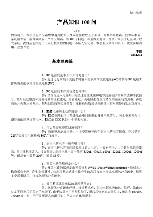
一、性能特点及适用范围LCAF220D24W300D-DF是我司设计生产的充电式模块电源,该电源具有体积小,转换效率高,性能稳定,原副边隔离,隔离强度高的优点;本产品采用金属外壳模块化封装,防尘防潮、抗干扰能力强;输入、输出端为接线端子形式便于连接;本产品电网适应能力强,可在较宽输入电压范围内工作;本产品具有输出短路、过压等保护功能。
另外,本产品具有智能充电功能,可对外接的24V电池充电,在交流断电时电池可不间断的对负载供电,具有防止电池过放电的保护功能;具有电源的状态显示;具有电池活化功能,手动或通过外部信号自动对电池进行活化维护。
本电源适用于电力配网自动化系统,电力智能箱变,环网柜以及其他行业需要不间断直流供电,要求较高的场合。
3.电源内部电路原理图1电源内部原理图图2电源内部隔离图4、面板说明图3电源面板说明1、充电及工作指示灯2、电池放电指示灯3、电池活化指示灯4、电池欠压指示灯5、电源故障(过压)指示灯6、手动活化启动按键7、手动活化退出按键8、手动电池投入按键9、手动电池退出按键1、接线端子5、接线说明5.1接线示意图图4接线示意图接线说明:K1K2K3为用户CPU等控制的继电器触点(触点容量无要求,但不可用光耦代替),R为电池活化放电电阻,负载为用户正常负载,电池为24V电池组。
接线端子容量300V/15A。
具体使用见下面使用说明。
5.2端子定义端子号端子名称定义端子号端子名称定义1ACL交流输入L相12BG遥控电池退出2PE保护接地13RL活化放电负载正3ACN交流输入N相14VG遥控公共接点4NC无电气连接15Vo-负载输出负5VC告警输入正16Vo-负载输出负6POK输入失电告警输出17Vo+负载输出正7HOK电池活化状态输出18Vo+负载输出正8VL电池欠压告警输出19B+电池接入正9VH电源故障告警输出20B+电池接入正10HK遥控活化启动21B-电池接入负11HG遥控活化退出22B-电池接入负6、使用说明6.1电源状态指示充电,绿色,电池充电指示,电池充电时亮,电池放电或电池活化时熄灭;放电,红色,电池放电指示,电池放电时或电池活化时亮,电池充电及电池放电结束时熄灭;活化,黄色,电池活化时亮,否则熄灭;欠压,红色,电池或电源输出欠压时亮,否则熄灭;故障,红色,电源输出过压时亮,否则熄灭。
300w开关电源设计(图纸)

TND313/DRev 3, Sep-11High-Efficiency305 W ATX Reference Design Documentation Package© 2011 ON Semiconductor.Disclaimer: ON Semiconductor is providing this reference design documentation package “AS IS” and the recipient assumes all risk associated with the use and/or commercialization of this design package. No licenses to ON Semiconductor’s or any third party’s Intellectual Property is conveyed by the transfer of this documentation. This reference design documentation package is provided only to assist the customers in evaluation and feasibility assessment of the reference design. The design intent is to demonstrate that efficiencies beyond 80% are achievable cost effectively utilizing ON Semiconductor provided ICs and discrete components in conjunction with other inexpensive components. It is expected that users may make further refinements to meet specific performance goals.Table of Contents1.Overview (6)2.Specifications (7)3.Architecture Overview (8)4.Performance Results (13)5.Evaluation Guidelines (23)6.Schematics (24)7.Parts List (29)8.Critical Component Information (35)9.Resources/Contact Information (35)10.Appendix (36)List of TablesTable 1: Target Specifications (7)Table 2: Load matrix for efficiency measurements (13)Table 3: Load matrix for cross regulation measurements (15)Table 4: Transient load conditions (18)List of FiguresFigure 1: Reference Design Architecture Block Diagram (7)Figure 2: One switch forward topology and associated waveform (9)Figure 3: Active clamp forward topology and associated waveform (11)Figure 4: Efficiency vs percentage load from 20% to full load (13)Figure 5: Power factor vs percentage load (14)Figure 6: Efficiency vs percentage load from 5% to full load (14)Figure 7: 5 V and 5 V SBY outputs cross regulation vs load conditions (16)Figure 8: 3.3 V output cross regulation vs load conditions (16)Figure 9: 12 V1 and 12 V2 outputs cross regulation vs load conditions (17)Figure 10: -12 V output cross regulation vs load conditions (17)Figure 11: 5 V output transient load response (18)Figure 12: 12 V1 output transient load response (18)Figure 13: 12 V2 output transient load response (19)Figure 14: 3.3 V output transient load response (19)Figure 15: 5 V output voltage ripple at full load (20)Figure 16: 3.3 V output voltage ripple at full load (20)Figure 17: 12 V1 output voltage ripple at full load (20)Figure 18: 12 V2 output voltage ripple at full load (21)Figure 19: -12 V output voltage ripple at full load (21)Figure 20: 5 V SBY output voltage ripple at full load (21)Figure 21: Holdup time at full load (22)Figure 22: Input inrush current (22)Figure 23: ATX solution boards in ATX enclosure (24)Figure 24: PFC controller PCB board schematic (25)Figure 25: EMC component board (25)Figure 26: Active clamp controller PCB board schematic (26)Figure 27: Supervisory and 3.3 V post regulator controller PCB board schematic (27)Figure 28: Main PCB board schematic PFC and standby section (27)Figure 29: Main PCB board schematic active clamp stage section (28)Figure 30: Main PCB board schematic 3.3 V post regulator section (28)1. OverviewON Semiconductor was the first Semiconductor company to provide an 80 PLUS open reference design for an ATX Power Supply in 2005. This 1st generation reference design, was certified and met all the requirements of the 80 PLUS program. Following on this successful 1st generation design, ON Semiconductor is introducing its improved 2nd Generation reference design. This 2nd generation design utilizes newer ICs from ON Semiconductor that enable this design to exceed 80% efficiency starting at 20% load across different line conditions with ample margin to spare.This reference document provides the details behind this 2nd generation design. The design manual provides a detailed view of the performance achieved with this design in terms of efficiency, performance, thermals and other key parameters. In addition, a detailed list of the bill-of-materials (BOM) is also provided. ON Semiconductor will also be able to provide technical support to help our customers design and manufacture a similar ATX power supply customized to meet their specific requirements.The results achieved in this 2nd generation design were possible due to the use of advanced new components from ON Semiconductor. These new ICs not only speeded up the overall development cycle for this new design, but also helped achieve the high efficiencies while at the same time keeping a check on the overall cost. With the use of these new ICs, ON Semiconductor has proven again that the emerging requirements for high efficiency desktop power supplies can be met and further, can be optimized to meet specific performance vs. cost goals.This 2nd generation design consists of a single PCB designed to fit into the standard ATX enclosure along with a fan. Figure 1 below presents the overall architecture employed in this design – detailed schematics are included later in this design manual. As seen in figure 1, this design employed an Active Clamp forward topology using the new, highly integrated Active Clamp Controller IC from ON Semiconductor – NCP1562. A Continuous Conduction Mode (CCM) Power Factor Correction (PFC) IC was employed for the active PFC circuit. This IC, the NCP1653 provides an integrated, robust and cost-effective PFC solution. The standby controller, NCP1027, is an optimized IC for the ATX power supply and incorporates a high-voltage MOSFET. On the secondary side, this architecture employs a post regulator approach for generating the 3.3 V output. This is an alternative approach to the traditional magnetic amplifier (Mag Amp) approach. Though ON Semiconductor believes that this post regulator approach provides the highest efficiency amongst the different means of generating these outputs in the power supply, it is important to note that if the customer desires to use a different approach, that is possible – i.e. a similar design can be developed that utilizes all the other pieces of this architecture without the post regulator and still achieve very good results.With the introduction of this 2nd generation, high-efficiency ATX Power Supply, ON Semiconductor has shown that with judicious choice of design tradeoffs, optimum performance is achieved at minimum cost.Figure 1: Reference Design Architecture Block Diagram2. SpecificationsThe design closely follows the ATX12V version 2.2 power supply guidelines and specifications available from , unless otherwise noted. For instance, our reference design had a target of +/- 5% tolerance for both the 5 V and 5 Vstandby outputs. Further, the efficiency targets for the 80 PLUS program and the EPA’s Energy Star specification – Energy Star Program Requirements for Computers, version 4.0 that is set to take effect from July 20, 2007 – were targeted. Key specifications are included in Table 1 below.Output Current Tolerance (%) Ripple/Noise(mV) Min. (A) Max (A)5 V 0.3 22 ± 3.350 5 V standby 0.0 2.5 ± 3.350 12 V 1.0 18 ± 5.0120 - 12 V 0.0 1 ± 10120 Table 1: Target SpecificationsTarget specifications for other key parameters of the reference design include: -Efficiency: Minimum efficiency of 80% for 20%, 50% and 100% of rated output load conditions as defined by the 80 PLUS requirements as well as the Energy Star specification.-Power Factor: Power factor of 0.9 or greater at 100 % load.-Input Voltage: Universal Mains – 90 Vac to 265 Vac, 47 – 63 M Hz.-Output Power: Total maximum output power is 305 W.-Safety Features: As per the ATX12V specification, this design includes safety features such as OVP, UVP, and OCP.-This design meets the IEC1000-3-2 requirements over the input line range and under full load conditions.-This converter was designed for a 20 ms minimum Hold-up time.-Physical dimensions: This converter is designed to fit into the standard ATX enclosure with dimensions of 150 mm x 140 mm x 86 mm.3. Architecture OverviewBefore discussing the power supply architecture of the Generation 2 design, it is worth reiterating the design goals. We are tasked with providing a flexible power platform, which is required to have the lowest cost and highest efficiency that can be packaged in a small volume. The architecture must deliver a minimum of 80% efficiency over a wide range of operating conditions (high-line and low-line) as well as rated output load conditions (20% load and above). In addition we require a robust design solution having low parts count to provide the same performance on a unit to unit basis in a high volume manufacturing environment.The architecture selected follows a traditional two stage conversion approach as illustrated in Figure 1. It is worth noting that in order to achieve 80% efficiency overall, the efficiency of each of the two conversion stages must exceed 90 %. The front-end is a universal input, active power factor boost stage delivering a constant output voltage of 385 V to the active clamp stage. The second stage consists of two, dc-dc converters. The first down-stream converter processes 290 W required by the system in the form of tightly regulated +/-12 V, +5 V and +3.3 V outputs. The second converter delivers 15 W of standby power to another isolated 5 V rail.ON Semiconductor has developed multiple power management controllers and MOSFET devices in support of the ATX program. Web based data sheets, design tools and technical resources are available to assist design optimization. The ICs, supporting the ATX Generation 2 platform, are the NCP1653 PFC controller, the NCP1562 active clamp controller, the NCP4330 post regulator, the NCP1027 standby controller, and the NTP48xx family of MOSFET synchronous rectifiers. It is not possible to discuss the tradeoffs involved in each conversion stage at length, but the selection of the activeclamp forward converter topology is a key one and will be covered in depth. Each controller is highly integrated and offers the lowest external parts count available.PFC StageThere are a variety of PFC topologies available. These include discontinuous conduction mode (DCM), critical conduction mode (CRM) and continuous conduction mode (CCM). At this power level, CCM is the preferred choice and the NCP1653 will implement a IEC1000-3-2 compliant, fixed frequency, peak current mode PFC boost converter with very few external components.DC to DC (Main) ConverterThe selection of the dc-dc down stream converter is at the heart of the 80% solution. The traditional work horse of the ATX market has been the single switch forward converter operating at a switching frequency of 100 kHz. The converter and its associated drain waveform are illustrated in Figure 2. This topology is robust and delivers good full load efficiency performance at minimal cost. However, as power levels increase and regulatory requirements and energy conservation agencies drive for higher efficiency under all load conditions, the single switch forward topology in its simplest form is reaching its limit.Figure 2: One switch forward topology and associated waveformThere are several technical reasons for this. First, because the main transformer is reset via an auxiliary winding across the input bus, the duty cycle is limited below 50%. Second, because of this reset mechanism there is always a dead time interval, during each converter cycle, when no power is flowing. These two constraints have negative implications on the silicon utilization of the primary switch requiring a costly, large area die to be selected. The primary switch’s conduction loss is given by (1))(*2*)(on DS R P I D conduction loss P =(1)where, D is the duty cycle, I P is the primary current and R DS(on) is the switch on resistance. The topology is a hard switched topology with the primary switch being driven on with 385 V across it each switching cycle. The capacitive switch loss are given by (2),f DS V OSS C capacitive loss P *2*21)(= (2)where, C OSS is the switch output capacitance, V DS is the drain to source voltage and f is the operating frequency. Capacitive losses dominate at light load. Hence a switch selected for full load performance will suffer at light load because of its large drain source capacitance. Reviewing these two loss equations, it becomes apparent for efficiency enhancement under both full load and light load operation, a topology is required that allows the primary switch to operate at lower current and voltage stress. As the loss terms appear as current and voltage squared, small reductions in primary current I P and switch voltage V DS significantly improve performance.The active clamp forward converter illustrated in Figure 3 represents the ultimate extension of the single switch converter and provides these benefits. Instead of using an auxiliary winding, transformer reset is achieved using a clamp capacitor and an auxiliary switch. The reset period, controlled by the auxiliary switch now extends to the interval ()S T D *1−, completely eliminating the previous dead time interval. To maintain flux balance in the main transformer core, the reset voltage across the clamp capacitor isdetermined by the expression ()D D in V −1*. The duty cycle D of the single switch forwardconverter can extend beyond 50%, limited only by the primary switch’s maximum voltage rating.Figure 3: Active clamp forward topology and associated waveformFor a given set of conditions and power throughput, operating at extended duty cycles allows for a lower primary current. This in turn allows the selection of a smaller, lower cost die. Let’s look at a design example to illustrate this point.To reduce cost, a 150 μF bulk capacitor (instead of a 470 μF conventional value) is selected to provide 20 ms of hold up time. Using the energy storage equation given by (3),()ηtime up Hold Delivered Power V V C Energy f i **2122=−= (3)where, V i and V f are the initial and final voltages of the input capacitor, respectively. The initial voltage is 385 V and converter efficiency is 90%, allows us to calculate the final voltage V f to be 250 V. In the case of a conventional single switch design, the maximum duty cycle we can practically select and avoid transformer saturation is 0.45. The switch voltage stress is 2 x 250 V. With the active clamp single switch forward, the duty cycle can be extended to 0.67 and the voltage stress on the switch is Vin / (1-D) or 3.03 x 250 V. Each converter has to process 290 / 0.9 or 322 W from the primary bulk source. At nominal 385 V bulk, the average primary current is 0.84 A. Factoring in the primary switch duty cycle D, the peak current I P in the traditional forward converter is 0.65 / 0.45 or 1.44 times larger than the active clamp approach. Based on the conduction loss equation given by (1), we see that the 1.44 ratio holds true for conduction loss in the primary switch. Put another way, we can choose a MOSFET with 44% higher R DS(on) in the active clamp topology and have the same conduction loss. This is significant, as we can achieve better silicon utilization, lower cost and lower drain capacitance. By reviewing the data sheets from high voltage MOSFET vendors, it is possible to compare output capacitance C OSS versus R DS(on) as a function of die size. For example as MOSFET resistance increases from 3.6 Ω to 4.8 Ω, the output capacitance reduces from100 pF to 70 pF. The resonant nature of the active clamp allows the switch be turned on at 300 V instead of the conventional 400 V. These two effects allow a reduction in capacitive switching loss of 39% over a conventional design. Again, a significant improvement remembering that light load efficiency is determined predominately by switching loss. The example above illustrates how small changes in switch stress can impact overall cost and performance.The same argument relating to increased duty cycle operation extends to the secondary by proportionally reducing output rectifier loss. Since the secondary loss is a dominant factor at full load, an additional efficiency improvement/ cost benefit is realized. To achieve the ultimate efficiency, synchronous rectification is required on the +12 V and +5 V outputs. The single switch active clamp forward is very suitable to drive synchronous rectifiers directly from the secondary windings without the need for expensive gate drivers or additional delay timing circuitry.To allow designers to capitalize on the benefits inherent in the active clamp topology, the NCP1562 has been developed to capture all the necessary control features within a 16 pin package. The full featured controller has been designed for tight tolerance on all parameters, including the maximum duty cycle limit and the important soft stop function. To boost efficiency and maintain tight regulation, instead of the conventional magnetic amplifier post regulated approach, the 3.3 V output is derived from the 5 Volt winding of the main transformer. The MOSFET drivers, timing, synchronization and control functions to support this output are provided by the NCP4330 controller. A 6 W improvement in the loss budget is achieved when this approach is adopted. Gate charge and R DS(on) have been optimized in the NTP48xx family of MOSFETs and provide synchronous rectification for both the 3.3 V and 5 V outputs.Standby PowerThe NCP1027 integrates a fixed frequency current mode controller and a 700 volt MOSFET. The NCP1027 is an ideal part to implement a flyback topology delivering 15 W to an isolated 5 V output. At light loads the IC will operate in skip cycle mode, thereby reducing its switching losses and delivering high efficiency throughout the load range.4. Performance ResultsThe evaluation of the reference design focused on several areas including efficiency, power factor, cross regulation and transient load response. Design optimizations may be needed to customize this reference design to meet specific requirements.The converter efficiency is measured according to the operating conditions detailed in Table 2. The converter efficiency is measured at 100 Vac, 115 Vac and 230 Vac at 50 Hz. The converter achieves over 80% efficiency with room to spare over all load conditions as shown in Figure 4. The output voltages used for the efficiency calculations are measured at the end of the power cables. The fan is disabled for measurements at or below 20% load. The fan is automatically enabled once the load exceeds 60 W or 20%. The fan is operational for 50% and 100% load measurements. Further increases in the efficiency can be obtained for 50% and 100% load conditions through fan speed control.Load Condition Output Current (A) 5 V 3.3 V 12 V1 12 V2 -12V5 V SBY 5 % 0.690 0.540 0.385 0.385 0.030 0.070 10 % 1.390 1.070 0.770 0.770 0.070 1.390 15 % 2.080 1.610 1.150 1.150 0.100 0.210 20 % 2.7802.150 1.510 1.510 0.140 0.280 50 % 6.950 5.3703.845 3.845 0.350 0.700 100 %13.900 10.7407.695 7.6950.700 1.400Figure 4: Efficiency vs percentage load from 20% to full loadThe power factor exceeds 0.9 over all operating conditions as shown in Figure 5.Figure 5: Power factor vs percentage loadIn Figure 6, the efficiency measurements are shown from 5% load to full-load. Note that neither the 80 PLUS program nor the Energy Star specification require efficiencies above 80% for any output load below 20%. However, as can be seen in Figure 6, this reference design achieved 80% efficiency down to 16 % load.Figure 6: Efficiency vs percentage load from 5% to full loadOutput voltage cross regulation is measured according to the load conditions listed in Table 3. The results of the cross regulation measurements are shown inFigure 7 through Figure 10. Included in these figures are the tolerance requirements based on the target specifications listed in Table 1. The margin for the 5 V and 5 V SBY outputs can be increased by shifting up the regulation target for the 5 V outputs. It can also be improved by changing the weight of the 12 V and 5 V outputs in the regulation circuit.Load ConditionOutput Current (A)5 V(+/-3.3%)3.3 V(+/-4%)12 V1(+/-5%)12 V2(+/-5%)-12 V(+/-10%)5 V SBY(+/-3.3%)1 0.3 0.3 0 0 0 02 73 2 2 0.1 0.53 0.3 0.3 0 0 0 0.54 0.3 3 2 2 0.1 0.55 7 0.3 2 2 0.1 0.56 4 0.3 1 1 0.2 0.27 18 12 5 5 1 2.58 18 12 1 1 0.2 2.59 4 12 5 5 1 2.510 18 0.3 5 5 1 2.511 4 0.2 1 1 0.2 0.212 14 17 8 6 1 2.513 18 17 1 1 0.2 2.514 4 17 8 6 1 2.515 18 0.3 8 6 1 2.516 4 2 5 5 0.2 117 22 17 5 5 1 2.518 4 17 5 5 1 2.519 22 2 5 5 1 2.5Table 3: Load matrix for cross regulation measurementsFigure 7: 5 V and 5 V SBY outputs cross regulation vs load conditionsFigure 8: 3.3 V output cross regulation vs load conditionsFigure 9: 12 V1 and 12 V2 outputs cross regulation vs load conditionsFigure 10: -12 V output cross regulation vs load conditionsThe 5 V, 12 V and 3.3 V outputs are evaluated independently under transient load conditions. Each output is loaded at 50% and the load is reduced to 25% or increased to 75% of the maximum rated current. The transient voltage tolerance of each of the 5 V, 12 V and 3.3 V outputs is +/- 5%. Table 4 summarizes the transient load conditions and limits for each output. Transient waveforms are shown in Figure 11 through Figure 14.Output Minimum Load (A)Nominal Load (A)Maximum Load (A)Voltage under/overshoot (V) 5 V 5.5 11 16.5 ±250mV, ≤0.5V pk-pk 3.3 V 4.25 8.5 12.75 ±170mV, ≤0.34V pk-pk 12 V1 4.5 9 13.5 ±600mV, ≤1.2V pk-pk 12 V24.5913.5±600mV, ≤1.2V pk-pkTable 4: Transient load conditionsFigure 11: 5 V output transient load responseFigure 12: 12 V1 output transient load responseΔI LOAD = 11.5 A to 5.5 AΔI LOAD = 11.5 A to 16.5 AΔI LOAD = 9 A to 4.5 AΔI LOAD = 9 A to 13.5 AFigure 13: 12 V2 output transient load responseFigure 14: 3.3 V output transient load responseAll the outputs meet the transient voltage requirements under the evaluated conditions. The ripple voltage of each output is measured at the maximum load for each output. The output ripple is measured across 10 μF/MLC parallel 1000 μF low ESR/ESL termination capacitors. The target ripple is +/- 120 mV for the 12 V outputs and 50 mV for all other outputs. Figure 15 through Figure 20 show the output voltage ripple measurements. All outputs meet the voltage ripple requirements.ΔI LOAD = 9 A to 4.5 AΔI LOAD = 9 A to 13.5 AΔI LOAD = 8.5 A to 4.25 AΔI LOAD = 8.5 A to 12.75 AFigure 15: 5 V output voltage ripple at full loadFigure 16: 3.3 V output voltage ripple at full loadFigure 17: 12 V1 output voltage ripple at full loadFigure 18: 12 V2 output voltage ripple at full loadFigure 19: -12 V output voltage ripple at full loadFigure 20: 5 V SBY output voltage ripple at full loadThe required holdup time at full load is 20 ms. Holdup time is measured from the moment the AC power is removed to when the PWR_OK signal goes low. Figure 21 shows the holdup time at full load. Channel 1 is the AC power and Channel 2 is the PWR_OK signal. Holdup time is measured at 22.5 ms.Figure 21: Holdup time at full loadThe input inrush current of the system at 230 Vac at full load is measured at 28.8 A as shown in Figure 22.Figure 22: Input inrush current5. Evaluation GuidelinesEvaluation of the reference design should be attempted only by persons who are intimately familiar with power conversion circuitry. Lethal mains referenced voltages and high dc voltages are present within the primary section of the ATX circuitry. All testing should be done using a mains high-isolation transformer to power the demonstration unit so that appropriate test equipment probing will not affect or potentially damage the test equipment or the ATX circuitry. The evaluation engineer should also avoid connecting the ground terminal of oscilloscope probes or other test probes to floating or switching nodes (e.g. the source of the active clamp MOSFET). It is not recommended to touch heat sinks, on which primary active components are mounted, to avoid the possibility of receiving RF burns or shocks. High impedance, low capacitance test probes should be used where appropriate for minimal interaction with the circuits under investigation. Particular care should be taken when probing the high impedance input pins of the NCP1653 power factor controller and the NCP1562 active clamp controller. As with all sensitive switchmode circuitry, the power supply under test should be switched off from the ac mains whenever the test probes are connected and/or disconnected.The 3.3 V output does not have a minimum load requirement and a preload resistor is included in the -12 V output.The NCP1027 standby flyback converter will be operational as long as there is ac mains voltage applied to the system. This auxiliary converter can be evaluated by merely applying the mains voltage to the board. The supervisory IC enable input and monitoring circuitry will have to be disabled. The supervisory circuitry will normally cause a shutdown of the PFC (and the main converter) if the 3.3 V, the 5 V and the 12 V outputs are not sensed at their nominal voltage.The evaluating engineer should also be aware of the idiosyncrasies of constant current type electronic loads when powering up the ATX demonstration unit. If the loads are adjusted to be close to the ATX’s maximum rated output power, the unit could shut down at turn on due to the instantaneous overloading effect of the constant current loads. As a consequence, electronic loads should be set to constant resistance mode or rheostats should be used for loads. The other alternative is to start the supply at light to medium load and then increase the constant current electronic loads to the desired level.The board is designed to fit in a traditional ATX enclosure as shown in Figure23.Figure 23: ATX solution boards in ATX enclosure6. SchematicsThe power supply is implemented using a single sided PCB board. Added flexibility is provided by using daughter cards for the PFC (NCP1653), active clamp (NCP1562) controllers. A PCB board is also used for the 3.3 V post regulator (NCP4330) and supervisory controllers. This allows the use of newer generation controllers without the need of a complete re-layout of the main board. An additional daughter card is used for EMC components. The individual PCB board schematics are shown in Figure 24 through Figure 27.The schematic of the main PCB board is divided in three sections: PFC & standby section, active clamp section, and the post regulator section as shown in Figure 28 through Figure 30, respectively.Figure 24: PFC controller PCB board schematicFigure 25: EMC component boardFigure 27: Supervisory and 3.3 V post regulator controller PCB board schematicFigure 28: Main PCB board schematic PFC and standby sectionFigure 29: Main PCB board schematic active clamp stage sectionFigure 30: Main PCB board schematic 3.3 V post regulator section7. Parts ListThe bill of materials (BOM) for the design is provided in this section. To reflect theschematics shown in the previous section, the BOM have also been broken into differentsections and provided in separate tables – Table 5 through Table 9.It should be noted that a number of components used during the development cycle werebased on availability. As a result, further cost reductions and better inventorymanagement can be achieved by component standardization. IE, the unique part numberscan be SIGNIFICANTLY reduced by standardization and re-use of component valuesand case sizes. This will result in a lower cost BOM and better inventory management.Description Part Numbers Qty 0.1µF, ±10%, 500V, X7R, Case Size 1812 VJ1812Y104KXEAT 3 0.1µF, ±10%, 50V, X7R, Case Size1206 B37872K5104K060 18 0.1µF, ±20%,300VAC, Interference Suppression CapX2 PHE840EB6100MB05R17 2 0.22uF, ±20% ,300VAC, Interference Suppression CapX2 PHE840EX6220MB06R17 1 270µF, ±20%, 400V, -40°C to +85°C, B43501 series , Snap-In, Pitch 10mm B43501A9277M000 1 100pF, ±10%, 1kVDC,High voltage ceramic disc Capacitor, -25°C to +85°C DEBB33A101KC1B 2 100pF, ±5%, 50V, COG, Case Size1206 B37871K5101J060 1 1nF, ±20% , 100V , Stacked-film capacitor, MMK series , 5mm Pitch MMK5 102M100J01L4 BULK 2 1nF, ±10%, 1kVDC,High voltage ceramic disc Capacitor,-25°C to +85°C DEBB33A102KA2B 2 1nF, ±20%,, 440VAC,Interference Suppression CapY1 PME294RB4100MR30 2 1nF,±20%, ,440/250VAC,Interference Suppression CapX1/Y2 2252 812 35 027 1 1nF, ±10%, 100V, COG, Case Size1206 B37871K1102J560 5 4.7nF, ±10%, 1kVDC, High voltage ceramic disc Capacitor, -25°C to +85°C DEBB33A472KA3B 1 4.7nF,±10% ,440/250VAC,Interference Suppression CapX1/Y2 2252 812 35 427 1 10nF, ±20% , 100V , Stacked-film capacitor, MMK series , 5mm Pitch MMK5 103M100J01L4 BULK 1 10nF, ±10%, 50V, X7R, Case Size1206 B37872K5103K060 1 22nF, ±20% , 100V , Stacked-film capacitor, MMK series , 5mm Pitch MMK5 223M100J01L4 BULK 1 2n2F, ±5%, 50V, COG, Case Size1206 B37871K5222J060 1 470pF, ±5%, 50V, COG, Case Size1206 B37871K5471J060 1 10µF, ±20%, 16V,-40°C to +85°C, Type VR, Radial, Pitch 2mm, Pb Free UVR1C100MDD 4 220µF, ±20%, 25V,-40°C to +85°C, Type VR, Radial, Pitch 3.5mm, Pb Free UVR1E221MPD 1 3300µF, ±20%, 10V,-40°C to +85°C, Type VR, Radial, Pitch 5mm, Pb Free UVR1A332MHD 1 47µF, ±20%, 25V,-40°C to +85°C, Type VR, Radial, Pitch 2mm, Pb Free UVR1E470MDD 1 2200µF, ±20%, 10V,-40°C to +85°C, Type PM, Radial, Pitch 5mm, Pb Free UPM1A222MHD 2 220µF, ±20%, 25V,-40°C to +85°C, Type PW, Radial, Pitch 3.5mm, Pb Free UPW1E221MPD 2 470E, ±1%, 0.25W, Case Size 1206 MCR18 EZH F-4700 1 0.2E, ±1%,1W, Case Size 2010 CRL1206-FW-0R20E_ 3 0E022, ±5%, 3W,Wire Wound Resister BSI680E022±5%±100ppm/°C 1 100E, ±1%, 0.25W, Case Size 1206 MCR18 EZH F-1000 1 100E, ±1%, 0.25W, MFR EROS2CHF1000 2 10E0, ±1%, 0.25W, Case Size 1206 MCR18 EZH F-10R0 2 10E, ±1%, 0.5W, Case Size 2010 MCR50-JZH-J 10R0 5。
CM6901中文

Ns1 := Npmin Nratio1
Ns1 = 3.023
二次側繞組
Vin_nor
Nratio2 :=
Topology ⋅Trnum
(Vout2 + Vmosfet)⋅1.15
Nratio2 = 14.223
Ns2 := Npmin Nratio2
Ns2 = 3.023
二次側繞組
Bmax:=
⎛⎜ ⎜
10 Vs5 ( Fsw ) Vs6 ( Fsw )
5
2 .10 4
4 .10 4
6 .10 4
Fr Fmin>=Fr
8 .10 4
1 .10 5
1.2 .10 5
Fsw Switch Frequency
1.4 .10 5
1.6 .10 5
1.8 .10 5
Fmax
2 .10 5
圖一 SRC 負載曲線圖
SRC V.S LLC
用於直流輸出之共振式轉換器主要以串聯共振(Series resonant)為主架構,主 要分成兩種負載曲線的操作區域,SRC 操作在共振點之上(操作在電感性負載區), LLC 操作在共振點之下與第二共振點之間(操作在電容性負載區間),以圖一 SRC; 圖二 LLC 為負載曲線圖來做說明。
Design specifications.
k ≡ 103
m ≡ 10− 3
Input Specifecation
μ ≡ 10− 6
n ≡ 10− 9
p ≡ 10− 12
Vin_max:= 400
Output Specifecation
Vin_min:= 330
Vin_nor := 395
Vout1 := 12
300w开关电源方案
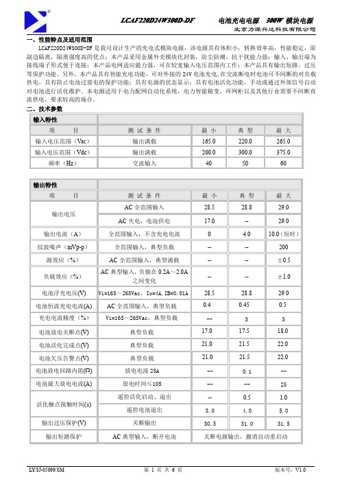
300W开关电源方案简介本文档介绍了一个300W的开关电源方案,用于提供稳定可靠的电源供应。
开关电源是一种将交流电转换为直流电的电源,通过开关管的开关动作来实现电压和电流的转换。
本方案采用了先进的电路设计和高效的开关管,以提高电源效率和稳定性。
方案设计输入电路300W开关电源的输入电压范围通常为220VAC或110VAC,本方案针对220VAC设计。
输入电路主要由滤波器、整流器和变压器组成。
滤波器用于滤除输入电压中的高频噪声,以保证输出电压的稳定性。
常见的滤波器电路包括Pi型滤波器和L型滤波器。
整流器将交流电转换为直流电,常见的整流器电路有全波整流和半波整流。
全波整流器可以实现较高的转换效率。
变压器用于将输入电压变换为适合开关电源工作的低压电压。
变压器一般由高频变压器和输出电感器组成,以提供高效的功率转换。
控制电路开关电源的控制电路主要包括开关管驱动电路和反馈控制电路。
开关管驱动电路负责控制开关管的开关动作,并控制输出电压。
常见的开关电源控制电路有固定频率PWM控制和变频控制。
反馈控制电路用于监测输出电压并调整开关管的开关动作,以稳定输出电压。
反馈控制电路一般由比较器、误差放大器和反馈元件组成。
输出电路输出电路主要由输出电感器、输出电容和负载组成。
输出电感器用于平滑输出电流,防止电流突变。
输出电容则用于平滑输出电压,提供稳定的负载。
负载是指连接在开关电源输出端的设备或电路,可以是各种电子设备、通信设备或其他电子装置。
负载的功率需小于或等于300W。
优点与特点高效率300W开关电源采用了高效率的开关管和控制电路,以减少功耗并提高转换效率。
高效率意味着更少的能量损耗,更低的温度和更长的使用寿命。
稳定性本方案采用了反馈控制电路来稳定输出电压,同时使用优质的电子元件和合理的电路布局,以提供稳定可靠的电源供应。
稳定的输出电压对各种设备和电路的正常运行至关重要。
可靠性300W开关电源采用了与国际标准相符的设计和制造工艺,确保产品的质量和可靠性。
300W AC DC 电源模块说明书

300W,165-264V AC Input,Dual outputAC/DC battery charging module power supplyRoHSFEATURES●Specially designed for Distribution Automation terminal design,suitable for 220Vdc operating mechanism,and it can charge for capacitor of 50000uF/250V ●Maximum instantaneous power up to 340W●With charging function,the 24V (6-30AH)output Lead-acid battery can be charged,when system connected with battery,it can be used as uninterrupted power supply●Designed in accordance with the power-related requirements of the State Grid Corporation,the main technical indicators meet the relevant industry standards●Battery reverse polarity protection,battery under voltage protection●Output over-current,over-voltage protection ●2.5KVAC high isolation voltage●Industrial grade operating temperature:-40℃to +70℃●Chassis mountingMBP300-2A27D27220is AC/DC battery charge power converter offered by Mornsun.It features wide input voltage range,taking both DC and AC input voltage,output over-current,over-voltage protection,strong ability in adapting power grid.This product has power working status display and Intelligent charging function,it can used to charge the 24V lead-acid battery,when AC is power-off,the battery can supply power to the load;it has battery over discharge protection function,Designed specifically for distribution automation terminal (DTU /FTU).It is widely used in the power industry switch substations,power substation,RMU,Intelligent Package Substation,Intelligent Switch Controller and other industries which need uninterrupted power supply.Selection GuidePart No.Output PowerNominal Output Voltage and Current Maximum Output PowerEfficiency(220VAC,%)(Vo1/Io1)(VB/IB)(Vo2/Io2)MBP300-2A27D2722062.5W27V/1.0A27V/0.5A220V/0.1A340W(No more than 20s,5mins once )80(Io1=1A,Io2=0.1A,disconnect the battery)Input SpecificationsItemOperating Conditions Min.Typ.Max.Unit Input Voltage Range AC input 165220264V AC DC input200310370VDC Input Frequency 475063Hz Input Current 220V AC,Typical load -- 1.0--AHot PlugUnavailableOutput SpecificationsItemOperating Conditions Min.Typ.Max.UnitRated Output CurrentInput voltage range Io1--1--A Io2--0.1--Peak Output Current *Input voltage range Io1(No more than 20s,5mins once,Io2≤0.1A)----6Io2(No more than 20s,5mins once,Io1≤1A)---- 1.36Output Voltage Input voltage range Vo1(Disconnect the battery)--27--VDC Vo2(Adjustable)200220240Line RegulationFull loadVo1--±0.5--%Vo2--±1--Load Regulation0%-100%load Vo1--±1--% Vo2--±5--Ripple&Noise**20MHz bandwidth(peak-to-peak value)(Io1=1A,Io2=0.1A,disconnect the battery)Vo1--200300mVVo2--2000--Floating Charge Voltage Room temperature,Io1=1A,Io2=0AVB--27--VDCBattery Charge Current Room temperature,Io1=1A,Io2=0AIB--0.5--A Battery Discharge Cut-off point Typical load Vo120.52121.5VDC Battery Discharge Cut-off Delay Time Typical load--3--sBattery Reverse Polarity Protection The green and the red lights are turn off,when the battery has been connected.Short Circuit Protection Input voltage range,disconnect the battery Hiccup,Continuous,self-recovery Over-current Protection Input voltage range,disconnect the battery Io1--16--A Over-voltage Protection Input voltage range,disconnect the battery----34VDC Hold-up Time Room temperature,220V AC input,Po=20W--0.3--s Note:*①When the ambient temperature exceeds50℃,Io1and Io2single peak current continuous output time can not exceed15s;②Io1and Io2can not simultaneously output peak current,product peak output power should not be more than340W.(Battery charging power included) **Ripple and noise are measured by“parallel cable”method,please see AC-DC Converter Application Notes for specific operationGeneral SpecificationsItem Operating Conditions Min.Typ.Max.UnitIsolation Voltage Input-outputTest time:1min,leakage current setting value:5mA2500----VAC Input-case2500----Output-case2500----Output-output1500----Impulse Voltage Input-output Apply5kV impulse test voltage between input andoutput.Add1.2/50us impact waveform,includingthree positive impulse and three negative impulsewhose time interval is no less than5seconds.And thereshould not have disruptive discharge during the test.5000----V Input-case5000----Output-case5000----Isolation Resistance Input-output Room temperature50----MΩInput-case Room temperature50----Output-case Room temperature50----Operating Temperature*-40--+70℃Storage Temperature-40--+85Shell Operation temperature*----+80Storage Humidity----95%RH MTBF MIL-HDBK-217F@25℃>100,000hNote:*①When the ambient temperature exceeds50℃,it should be taken the cooling method of force air cooling or post cooling to ensure that the module shield temperature is not more than80℃.②When the ambient temperature is lower than-10℃,the product should be operated with rated load for1mins,before it output340W peak power. Physical SpecificationsCasing Material MetalPackage Dimensions200.00*102.00*45.00mmWeight850g(Typ.)Cooling method Free air convectionEMC SpecificationsEMS ESD IEC/EN61000-4-2Contact ±8KV Perf.Criteria B RS IEC/EN61000-4-330V/m perf.Criteria A EFT IEC/EN61000-4-4±4KV perf.Criteria B Surge IEC/EN61000-4-5line to line±2KV/line to ground±4KV perf.Criteria B CS IEC/EN61000-4-610Vr.m.s perf.Criteria A Voltage dips,short interruptionsand voltage variations immunityIEC/EN61000-4-110%,70%perf.Criteria BPrinciple block diagramFig1.Internal principle diagram Wiring Description1.Wiring diagram2.Terminal DefinitionTerminal No.Terminal name Definition1AC(L)AC input L phase2Protective grounding3AC(N)AC input N phase4-Vo1(B-)Control unit(-)Battery input(-)5B+Battery input(+)6+Vo1Control unit(+)7NC No electrical connection 8+Vo2Operating mechanism(+) 9-Vo2Operating mechanism(-) 10NC No electrical connectionManual Instruction1.Power supply status indicatorCharge,AC input power,green light on,the battery is in charging or floating charging status.Discharge,AC input power off,green light off,red light on,the battery is in discharging status.Reverse,when the input voltage off(or input voltage normal,Vo1and Vo2output normal),but the green and red light are all off,which shows that the battery is polarity reversed.Please check the wiring diagram to re-connect the battery.Input voltage(V AC)Output voltage(VDC)Whether to connectthe batteryLEDPower state Vo1Vo2green light Red light22027220no connect on off Output normal220Batteryvoltage220connect on off Output normal,battery charging000no connect off off No output000connect off on No output,battery access to normal220→0Batteryvoltage220connect on→off off→onOutput normal,battery from charginginto the discharge000connect off off No output,reverse connection ofbattery22027220connect off off Output normal,reverse connection ofbatterye of PowerThe power supply can work when input is AC the alternating current.The power input current to load is powered by power supply, meanwhile charge battery in constant current and voltage.After the battery is charged,power supply to floating charge state automatically,this moment,the power supply float voltage and current to normal self discharge of battery.When AC input voltage off,the battery will continue to power for load,0switch time.When the battery output voltage is lower than the under voltage protection point and last for3-10S,the power supply will turn off automatically.Without AC input,pass external passive nodes make Vo1and B+in short circuit(short circuit time:1-2S,but pin should not be short for a long time,otherwise the battery will lose the protection function.)that can enable the battery to start the output.Vo2output Voltage:200Vdc–240Vdc continuously adjustable,The user can adjust the output voltage to the knob with“output voltage adjustment”.e of BatteryThe power supply can be equipped with24V,6-30AH lead acid battery or colloidal maintenance-free battery,The battery is connected to the battery terminal(B+、B-)of the power supply.We should make sure that the input voltage is off before connect or disconnect the battery.If the red light on after connected the battery,the battery connected normal;if the red light off when connected the battery,the battery polarity connected reverse,please check the wiring diagram to re-connect it.It is forbidden to short-circuit the battery.After connect with the battery,the over-current protection and short-circuit protection of Vo1will be disabled.Simple calculation of battery charging time:Battery capacity C(AH)/Charging current(A)Dimensions and Recommended LayoutAttention Matters in Application(1)Output please use wire that cross area is more than2.5mm²,input terminal should add10A/250V AC Fuse.(2)Please correct connection according to the wiring diagram,do not connect wrongly,AC input terminal is strictly prohibited connected with other terminals wrong,otherwise will cause permanent damage to power.(3)Vo2output peak current can not be long term work.(4)To further reduce the Vo1output ripple noise,the user can in the Vo1output parallel connection with one470–1000uF/50V electrolytic capacitor and1uF multilayer ceramic Capacitor.(5)The output of this product is not allowed to work in parallel.(6)The PE terminal of this product should be reliably connected to the earth,in order to improve the capability of anti-interference.(7)Casing will distribute heat when the power is during operating,in order to ensure the power dissipation is good,please keep a certain gap around the power supply to ensure the air flow smoothly,the temperature sensitive device as far as possible from the power.Note:1.Packing information please refer to Product Packing Information which can be downloaded from .Packing bag number:58220041;2.If the product is not operated within the required load range,the product performance cannot be guaranteed to comply with all parameters in the datasheet;3.Unless otherwise specified,parameters in this datasheet were measured under the conditions of Ta=25℃,humidity<75%with nominal input voltage and rated output load;4.All index testing methods in this datasheet are based on our Company’s corporate standards;5.We can provide product customization service,please contact our technicians directly for specific information;6.Specifications are subject to change without prior notice.Mornsun Guangzhou Science&Technology Co.,Ltd.Address:No.5,Kehui St.1,Kehui Development Center,Science Ave.,Guangzhou Science City,Luogang District,Guangzhou,P.R.China Tel:86-20-38601850-8801Fax:86-20-38601272E-mail:***************。
超频三电源基本型号和参数静音电源首选
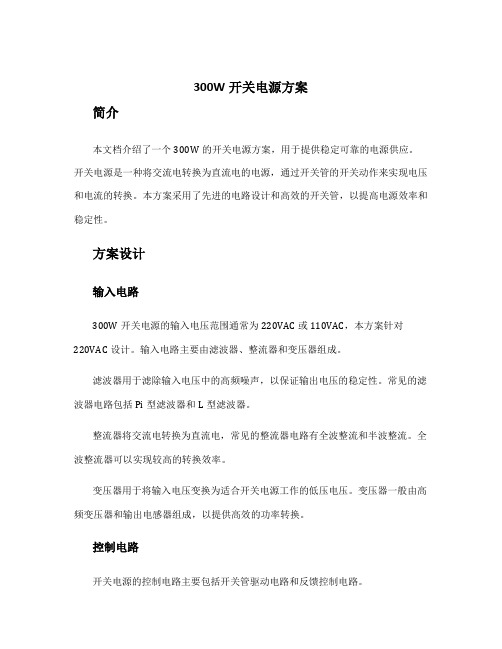
大理石3003C MA300P规格参数电源简介:大理石3003C版额定功率200W,最大功率300W,提供了1个20+4Pin主板电源接口,2个SATA接口。
另外,大理石3003C配备了超频三专利的120mm液压轴承静音风扇,在最安静的环境下也听不到一点声音,真正带给用户极致的静音享受。
同时,这款产品严格通过了国家3C认证,具有过压,欠压,过温,过流,过载橄榄石370静音版OL370P规格参数电源简介:橄榄石370静音版额定功率270W,符合ATX12V 2.3规范,提供了1个20+4Pin主板电源接口,1个6Pin显卡供电接口,4个SATA接口。
另外,橄榄石370静音版备配超频三专利的120mm液压轴承静音风扇,具有低转速、低噪音特点,在最安静的环境下也听不到一点声音,真正带给用户极致的静音享受。
同时,这款产品严格通过了国家3C认证,具有过压,欠压,过温,过流,过载等保护功能,加上一年换新,三年保修的周到售后服务。
最关键的是,这款电源性价比超高,绝对是学生、家庭、网吧用户首选。
技术、规格参数一览表:适用类型台式机适用平台Intel 双核及AMD双核、三核等处理器额定功率270瓦稳定功率300瓦(可持续24小时运行功率)PFC类型被动式电压范围180V——264V电源规范ATX12V 2.312V输出单路+12V增强输出转换效率75%以上待机功耗小于1瓦热管散热无风扇类型12厘米液压子弹头静音风扇主板供电20+4Pin 线长:420mmCPU供电4+4Pin 线长:420mm显卡供电6Pin 线长:450mmSATA接口4个线长:400+150+150+200mm大4pin接口3个线长:400+150+200mm特色技术ROSH 无铅制程、待机小于1瓦、液压子弹头静音风扇功能保护过压、欠压、过载、过流、过温、短路等保护功能安全认证3C、CE、ROSH 无铅制程平均无故障时间50000小时售后服务一年换新,三年保修适用范围Intel 双核及AMD双核、三核等处理器H3专业版H3-300-12规格参数电源简介:H3专业版是超频三为网吧用户量身打造的一款集节能、静音、稳定于一身的新型专业电源,以率先提供震撼业界的“三年换新”金牌服务和行业一流的顶级品质,完美贴合网吧用户需求。
一般的CPU故障有以下几种
一般的CPU故障有以下几种:散热故障、重启故障、黑屏故障及超频故障(当然CPU go to die 就不算了)。
一、CPU针脚接触不良,导致机器无法启动一般表现在突然无法开机,屏幕无显示信号输出,排除显卡、显示器无问题后,拔下插在主板上的CPU,仔细观察并无烧毁痕迹,但就是无法点亮机器。
后来发现CPU的针脚均发黑、发绿,有氧化的痕迹和锈迹,便用牙刷对CPU针脚做了清洁工作,然后问题就解决了。
故障的原因可能是因为制冷片将芯片的表面温度降得太低,低过了结露点,导致CPU长期工作在潮湿环境中。
而裸露的铜针脚在此环境中与空气中的氧气发生反应生成了铜锈。
日积月累锈斑太多造成接触不良,从而引发故障。
此外还有一些劣质主板,由于CPU插槽质量不好,也会造成接触不良,很多资料上都有此问题,最好的办法就是自己手动安装和固定CPU!二、挂起模式造成CPU烧毁一般的系统挂起并不会造成CPU烧毁,系统会自动降低CPU工作频率和风扇转速来节省能耗。
而挂起模式造成CPU被烧毁,均是超频后的CPU。
这全都因为风扇停止运转造成的。
主板上的监控芯片除可以监控风扇转速外,有的还能在系统进入Suspend(挂起)省电模式下,自动降低风扇转速甚至完全停止运转,这本是好意,可以省电,也可以延长风扇的寿命与使用时间。
过去的CPU处于闲置状态下,热量不高,所以风扇不转,只靠散热片还能应付散热。
但现在的CPU频率实在太高,即使进入挂起模式,当风扇不转时,CPU也会热得发烫。
这种情况并不是在每块主板都会发生,发生时必须要符合三个条件。
首先CPU风扇必须是3pin风扇,这样才会被主板所控制。
第二,主板的监控功能必须具备Fan Off When Suspend (进入挂起模式即关闭风扇电源),且此功能预设为On。
有的主板预设On,甚至有的在Power Management的设定就有Fan Off When Suspend这一项选项,大家可以注意看看。
12公斤重力发电led灯参数
LED灯作为一种节能环保的照明产品,受到了越来越多的关注和应用。
而12公斤重力发电LED灯作为一种新型的LED照明产品,其参数信息也备受关注。
本文将详细介绍12公斤重力发电LED灯的参数信息,以便读者更全面地了解这一产品。
一、产品型号:12公斤重力发电LED灯该LED灯的产品型号为12公斤重力发电LED灯,是一种利用重力发电原理来供电的LED照明产品。
二、功率与亮度1. 功率:12W该LED灯的功率为12W,属于较为节能的照明产品。
2. 亮度:800lm其亮度达到了800lm,能够提供良好的照明效果。
三、光色与色温1. 光色:白光该LED灯的光色为白光,适用于大部分室内环境的照明需求。
2. 色温:6000K色温为6000K,营造出明亮舒适的照明氛围。
四、光束角度光束角度:120°LED灯的光束角度为120°,能够有效扩散光线,提高照明覆盖范围。
五、使用寿命与保修1. 使用寿命:xxx小时该LED灯的使用寿命达到xxx小时,长时间稳定供电。
2. 保修信息:3年保修期在购物后的3年内,提供免费的维修与更换服务,保障产品的质量与使用体验。
六、其他参数1. 防护等级:IP65LED灯的防护等级为IP65,具有良好的防水防尘性能,适用于室内外各种环境。
2. 输入电压:AC 85-265VLED灯适用于广泛的输入电压范围,可在多种不同的电压环境下使用。
以上便是12公斤重力发电LED灯的各项参数信息,通过对这些参数的了解,读者可以更好地选择适合自己需求的LED照明产品。
希望本文对您有所帮助,谢谢!七、环保与节能12公斤重力发电LED灯作为一种利用重力发电原理来供电的照明产品,具有较高的能源利用率和环保性。
相比传统的光源,如白炽灯或荧光灯,LED灯具有更低的能耗和更长的使用寿命。
采用LED照明不仅能够减少能源的消耗,降低能源的浪费,还能够减少对环境的污染,降低碳排放。
LED灯的使用寿命长,减少了更换灯具的频率,减少了对资源的消耗,从而更好地保护了环境。
铁路信号设备测试手册

一、色灯信号机测试一、主要技术指标1.色灯信号机灯泡的端子电压为灯泡额定值(AC12V)的85%—95%(10。
2-11.4 V),调车信号为75%—95%(9.0-11.4 V ),允许信号为65%—85%(7。
8—10.2 V).副丝电压为主丝电压的90—95%(有的不达标)。
2.双丝灯泡的自动转换装置,当主丝断丝后应能自动转换至副丝,有断丝报警功能的,应报警。
3.机构发光二极管损坏数量达到30%时,不能影响信号显示的规定距离,并及时报警。
三、测试方法及要求1。
在色灯信号机调整前,先测试、调整电源屏信号机点灯输出电压。
电源屏输出电源在外电网波动变化条件下,信号机点灯输出电压应控制在220±10V.2。
点灯变压器(点灯单元)Ⅰ、Ⅱ次电压测试信号机被测灯位在正常点灯工作状态,用万用表交流电压档在变压器(点灯单元)I、II次侧端子上测得。
3。
主、副灯丝点灯端电压测试被测灯位在主丝工作状态,用万用表交流电压档在灯座主、回端子上测得主丝电压。
断开主丝,被测灯位在副丝工作状态,用万用表交流电压档在灯座副、回端子上测得副丝电压。
4.灯丝继电器交、直流电压测试信号机在正常工作状态,从微机监测上直读测得,或用万用表交、直流电压档在灯丝继电器相应接点端子上测得.5.灯丝继电器工作电流测试信号机在正常工作状态,从微机监测上直读测得,或用万用表交流电流档串入点灯回路上测得,或用钳形电流表将卡钳钳住点灯回路软线测得。
6.LED发光盘端压测试(以浙江万全LED发光盘为例说明)被测发光盘在工作状态,用万用表直流电压在档发光盘G、25%端子上测得100%LED 点亮电压.将25%端子配线移至75%端子,用万用表直流电压在档发光盘G、75%端子上测得75%LED点亮电压.此时应有灯丝报警。
四、测试仪表说明1。
MF14万用表。
2. 钳型电流表二、联锁道岔1。
ZD6、ZD7电动转辙机测试一、主要技术指标4 ZD7转极继电器转极电压/5 表示继电器交直流电压6 电机定子、转子线圈电阻1.ZD6系列:单定子工作电阻(2.85±0.14Ω)*2(ZDG—Ⅲ型)或(2.65±0.14Ω)*2(DZG型)刷间总电阻4.9±0.245Ω(ZDG—Ⅲ型)或5.1±0。
XL3003 220KHz 36V 4A开关电流降压型LED恒流驱动器说明书

220KHz 36V 4A 开关电流降压型LED恒流驱动器XL3003特点⏹8V到36V宽输入电压范围⏹0.21V输出电流采样电压⏹最大占空比100%⏹最小压差0.3V⏹固定220KHz开关频率⏹最大4A开关电流⏹内置功率MOS⏹出色的线性与负载调整率⏹内置频率补偿功能⏹内置热关断功能⏹内置电流限制功能⏹TO252-5L封装应用⏹降压恒流驱动⏹显示器LED背光⏹通用LED照明描述XL3003是一款降压恒流型LED驱动器,可工作在DC8V到36V输入电压范围,低纹波,内置功率MOS。
XL3003内置固定频率振荡器与频率补偿电路,简化了电路设计。
PWM控制环路可以调节占空比从0~100%之间线性变化。
内部补偿模块可以减少外围元器件数量。
图1. XL3003封装220KHz 36V 4A 开关电流降压型LED 恒流驱动器 XL3003引脚配置VIN SW CS GNDVC 12345TO252-5L图2. XL3003引脚配置表1.引脚说明引脚号 引脚名 描述 1 GND 接地引脚。
2 CS 输出电流采样引脚,CS 参考电压为0.21V 。
3 SW 功率开关输出引脚,SW 是输出功率的开关节点,金属片电气属性是SW 。
4 VC 内部电压调节器旁路电容引脚,需要在VIN 与VC 引脚之间连接1个1uF 电容。
5VIN电源输入引脚,支持8V 到36V DC 范围电压输入,需要在VIN 与GND 之间并联电解电容以消除噪声。
220KHz 36V 4A 开关电流降压型LED 恒流驱动器 XL3003方框图OCPVCVINCurrent Sense3.3V Regulator 0.21V ReferenceStart Up &UVLOCOMPOscillator 220KHzEACSGNDRS Latch and Driver3.3V 0.21VSWSwitch1:1000Thermal ShutdownVC Clamp图3. XL3003方框图典型应用XL3003CIN100uF/50VCOUT220uF/35VL1 100uH/4AD1 B540CC1105C21055312VIN4IOUT=0.21V/RCSVINVCSWGNDCSCC 105LED图4. XL3003系统参数测量电路220KHz 36V 4A开关电流降压型LED恒流驱动器XL3003订购信息产品型号打印名称封装方式包装类型XL3003E1 XL3003E1 TO252-5L 2500只每卷XLSEMI无铅产品,产品型号带有“E1”后缀的符合RoHS标准。
300w开关电源方案
300W开关电源方案概述本文档将介绍一种可以提供300W输出功率的开关电源方案。
开关电源是一种能够将输入电压转换为稳定输出电压的电源装置。
它使用开关器件(通常是晶体管或MOSFET)来控制输入电压的开关行为,从而实现调整输出电压的目的。
系统设计输入电路开关电源的输入端通常需要接受来自电网的交流(AC)电压。
为了适应不同的输入电压范围,我们将采用变压器和整流桥的组合。
变压器可以将电网提供的高电压降低为适当的中间电压,整流桥则将交流电转换为直流电。
滤波电路直流输出的电压经过整流后,仍然存在一些纹波和噪声。
为了降低这些干扰,我们需要设计一个滤波电路。
常用的滤波电路包括电容滤波和电感滤波。
电容滤波器通常用于去除高频噪声,而电感滤波器则用于去除低频纹波。
锁相环(PLL)为了确保开关频率稳定且与输入电压同步,我们将使用一种称为锁相环(Phase-Locked Loop,PLL)的技术。
PLL通过比较输入信号和参考信号的相位差,并调整输出信号的频率,从而使两者保持同步。
这将确保开关器件以恰当的时机开关,从而实现输出电压的稳定。
控制器开关电源的控制器负责监测和调整输出电压。
它通常由一个微处理器或专用的控制芯片实现。
控制器通过测量输出电压并与参考电压进行比较,控制开关器件的开关频率和占空比,以保持稳定的输出。
开关器件开关器件是实现开关电源功能的核心组件。
常见的开关器件包括晶体管、场效应晶体管(MOSFET)和双极性晶体管(BJT)。
它们通过开关行为控制输出电压。
选择适当的开关器件非常重要,因为它们的开关速度、功耗和可靠性等特性将直接影响到整个系统的性能。
反馈回路为了实现输出电压的稳定性,我们将使用反馈回路。
反馈回路通过将一部分输出电压引导回控制器,并与参考电压进行比较来调整开关行为。
采用合适的反馈网络设计可以实现很高的输出稳定性和响应速度。
性能参数输出功率:300W本方案设计的开关电源具有300W的输出功率,可以满足大多数低功率应用的需求。
如何计算UPS蓄电池配置及蓄电池的放电时间

UPS电池容量计算方法(常用的)功率(VA):电压×电流=VA值。
设备用瓦特表明电能需要,见瓦数乘以1.4即可得大致的VA值。
对于整体设备的功率则以其额定数为基准。
把所有设备的VA值汇总,将汇总值加上百分之三十的扩充容量,以备系统升级时用。
一般UPS配置计算:UPS电源功率(VA)×延时时间(小时数)÷UPS电源启动直流=所需蓄电池安时数(AH)例:山特C3KS延时4小时为我们来计算下:(山特C3KS的启动直流为:96V)3000伏安×4小时÷96V=125AH(需要125AH的电池才能满足4小时的供电)计算UPS蓄电池配置及蓄电池的放电时间蓄电池的放电时间要根据实际负载的功率来计算:I=(Pcosφ)/(ηEi)P:UPS的标称输出功率;cosφ:负载功率因数; PC、服务器一般取0.6~0.7η:逆变器的效率; 一般也取0.8(10KVA取0.85)Ei:电池放电终了电压,一般指电池组的电压。
求出电池最大放电电流后,即可从电池的各温度下放电电流与放电时间的关系图上查出相应的放电时间。
蓄电池的放电电流与放电时间不是线性的,有人认为20A放电5小时就要用100AH 的,这样就错了。
蓄电池的容量一般都是20HR(小时率)的,也就是说只有以5A放电20小时才是配100AH的,因为100AH的电池在5A可以放电20小时,在10A时只有9小时左右,20A时只有4小时左右。
但在2A时确可以放60小时以上。
这就是蓄电池放电时间与电流的非线性关系。
正因为非线性关系就有了下面这个表。
请大家先来熟悉一下下面的电池恒电流放电参数表,指在一定的电流下放电能达到多长时间UPS用的12V电池一般终止电压为10.5V。
以下算法是按电池在温度为25度时的计算结果,蓄电池的实际放电容量也与温度有关,如MF12-100的电池,在摄氏10度以0.1C电流放电,蓄电池能表现的容量约为85AH,3-5年后蓄电池随着内部老化放电时间会渐渐缩短,是正常现象。
UPS电池容量的计算方法

UPS电池容量的计算方法一般UPS配置以一下公式计算:UPS电源视在功率(VA)×功率因素×延时时长(小时数)÷UPS电源启动直流电压÷逆变器效率=所需电池安时数(AH)功率因数一般取,逆变器效率一般取,UPS电源启动直流电压根据不同型号而不同。
计算出了所需的安时数后,再根据UPS启动直流电压和实际使用的电池的安时数决定电池进行串联和并联。
例如:电池安时数=60000××÷192÷=UPS/EPS电池时间计算方法一、UPS电池时间计算方法计算蓄电池的最大放电电流值:I最大=Pcosф/(η*E临界*N)注:P → UPS电源的标称输出功率cosф → UPS电源的输出功率因数(UPS一般为)η → UPS逆变器的效率,一般为~(实际计算中可以取)E临界→蓄电池组的临界放电电压(12V电池约为,2V电池约为)N →每组电池的数量根据所选的蓄电池组的后备时间,查出所需的电池组的放电速率值C,然后根据:电池组的标称容量= I最大/C时间与放电速率C30分钟60分钟90分钟120分钟180分钟例如P=300KVA延时30分钟逆变器启动电压:U=360电池额定电压: U1=12V每组电池数量:N=U÷U1=360÷12=30节电池的最大放电电流:Imax=P×cosф÷(η×N×E)=300000VA×÷(×30×)=846A电池组的标称容量= 846÷=919AH电池组的总容量=919AH×30节×12V=330840AH需要用电池150AH 30节6组,电池柜6个,尺寸800*900*2000300KVA UPS尺寸为1800*1250*1800电池放出容量=负载的有功功率×支持时间/(电池电压×UPS逆变效率)=300000×*(360*=370二、 EPS电池时间计算方法计算蓄电池的最大放电电流值:I最大=Pcosф/(η*E临界*N)注:P → EPS电源的标称输出功率cosф → EPS电源的输出功率因数(EPS一般为1`)η → UPS逆变器的效率,一般为~(实际计算中可以取)E临界→蓄电池组的临界放电电压(12V电池约为,2V电池约为)N →每组电池的数量根据所选的蓄电池组的后备时间,查出所需的电池组的放电速率值C,然后根据:电池组的标称容量= I最大/C时间与放电速率C30分钟60分钟90分钟120分钟180分钟例如EPS YSJ-300KW延时30分钟电池的最大放电电流1058A=标称功率300000W×1÷(效率*30节*每节电池放电电压)电池组的标称容量= 1058÷=1150AH因此需要用电池150AH30节7组电池柜7个尺寸800*900*2000UPS电源计算公式及电池配置方法1、技术性能;2、质量保证;3、服务保证;4、产品价格。
LLC电路原理及实例应用

LLC电路应用实例原理图PFC + LLC 原理图 效率测试TPH3006PS TPH3206PS TPH3002PS TPH3202PS TPH3205WS TPH3206LD TPH3202LD氮化镓的特性介绍LLC是典型软开关电路。
因为开关损耗本来就很小,氮化镓 在此电路上改变的是‘死区时间’。
时间越小,损耗越小,使 用死区可调的IC即可上下管交合的时间硅材料FET氮化镓硬开关电路上的Vds开关损耗对比,氮化镓有明显优势 但LLC是软开关,这部分电路上损耗几乎一样。
Fs=Fo传统的高压硅材料MOSFET,COOL-MOSFET一般保能工作在低频。
高频特性变差很多。
主 要损耗加大发热问题。
但氮化镓支持工作在高频同时没有带来多少损耗的加大。
频率提高电路板子体积变小,成本 降低,同时效率会提高1%以上。
氮化镓FET与Cool‐Mosfet对比等同Rds(on)对比,相同条件 Parameters Static VDS RDS (25 ⁰C) Qg Qgd Dynamic Reverse Operation Co(er) Co(tr) Qrr trr Cool mosfet IPA60R160C6 600V @ 25 ⁰C 0.14/0.16 ohm 75 nC 38 nC 66 pF [1] 314 pF [1] 8200 nC [2] 460 ns [2] 氮化镓FET TPH3006PS 600V (spike rating 750V) 0.15/0.18 ohm 6.2 nC 2.2nC 56 pF [1] 110 pF [1] 54 nC [3] 30 ns [3]更小的死区时间 更小的反向恢复损耗 更小的反向恢复时间 更低的驱动损耗100mA驱动电流即可 更低的米勒效应/更低的开关损耗Qg 门极驱动电流大小 Qgd 与工作的Vds的开关波形有关。
厂用事故保安电源和不停电交流电源

厂用事故保安电源和不停电交流电源一.保安电源概述〔一〕保安电源的作用保安电源是专为大型汽轮发电机组配置的电源系统.在发电厂的锅炉、汽机和电气设备中,都有部分设备不但在机组运行中不能停电,而且在机组停机后的相当一段时间内也不能中断供电;还有一些设备需在机组事故停机时立即从备用状态投入运行;另有部分设备例如蓄电池组的充电设备则不论机组运行与否都不能较长时间失电.也就是说,它们对保证设备安全具有非常重要的意义.因此,供电给这些设备的电源系统应比一般的厂用电系统更可靠,这就是设置保安电源系统的原因.我们一般所说的保安电源实际上是指的交流事故保安电源系统,它包括正常运行的部分和事故备用的部分,共同组成完整的交流保安电源系统.保安电源系统是按全厂停电〔包括由系统引入的起动备用电电源也停电〕时能保证需要继续运转的设备有可靠的电源供电从而保证安全停机的原则来设计的.正常机组运行时或机组虽不运行但电厂的厂用电是由系统引入的起动备用电源供电时,接在保安电源上的设备也由电厂厂用电供电运行.如果由于某种原因发生厂用电失电而造成全厂停电,保安事故备用电源应投入供电,保证接在保安段的设备继续运行.交流保安电源供电的负荷一般是允许短时间停电的即允许短时间间断供电的,这是保安电源与不停电电源的区别.在发电厂还有一部分不允许间断供电的负荷即实际上是指电源间断时间极短不允许超过5毫秒例如计算机等负荷,短时中断供电的交流电源还不能满足这类负荷的需要,这类负荷在设计规程中简称为"0I"类负荷,应由不停电电源供电.容量为200MW以上的火力发电机组设置有交流保安电源.〔二〕交流事故保安电源的特点保安电源系统虽然在接线上看起来与一般低压厂用电没有区别,实质上由于其供电负荷的性质决定了保安电源系统具有以下特点:1.交流事故保安段的接线应与低压厂用电一致.交流事故保安段〔一般每台300MW机组分两段〕正常情况下必须由单元机组的低压厂用电供电,它是保安段的工作电源,所以,保安段的中性点接地方式应与低压厂用电系统一致.2.交流事故保安电源必须是独立可靠的电源.交流事故保安电源是保安段的备用电源,当由低压厂用电来的工作电源失电时由该备用电源投入供电,所以,这个电源的运行应不受本地区电力系统运行情况的影响.它不能取自本厂内的发电机组,也不能取自与厂内机组的高压起动备用电源联系密切的电网,应具有明显的独立性,这样才能保证在全厂停电时给保安段可靠供电.3.交流事故保安电源应具有快速投入的性能.为了保证故障情况下的机组安全和其它设备与人身安全,停电时间越短越好.为此,在保安段的工作电源失电时,事故备用电源应快速投入,一般不应超过10秒,这是对事故保安电源的基本要求.4.保安电源系统的接线应十分可靠.按照规程规定,保安段除工作电源和事故备用电源外,不再设置其它备用电源.这就要求保安电源系统应具有高度的可靠性.不但一次系统接线配置要合理完善,而且其控制、连动回路也必须可靠,任何情况下不得发生拒动现象.为此在保证实现必要的功能的前提下应尽量简化电气二次接线.〔三〕交流事故保安电源的负荷保安电源系统供电的负荷为交流事故保证负荷,简称为"0Ⅲ"类负荷,〔直流事故保安负荷简称为"0Ⅱ"类负荷〕在设计规程中这类负荷是指在发生全厂停电时保证机炉安全停运,过后能很快起动,或为防止危与人身安全需在全厂停电时继续供电的负荷.这些负荷大都是允许短时间中断供电的低压厂用负荷,它包括旋转电机负荷和静止负荷,主要有以下设备:1.汽轮发电机组的盘车电机和顶轴油泵,停机后仍需继续运转.2.机组的润滑油泵和密封油泵,停机后需继续运转.3.锅炉给水泵的润滑油泵.4.回转式空气预热器,它在锅炉停运后的一段时间内仍需继续转动以防止设备损坏.5.其它各种辅机的润滑油泵,例如风机、磨煤机的润滑油泵等;6.蓄电池组的充电装置.目前普遍都采用了硅整流充电装置,它在任何情况下不应长时间失电;当发生全厂停电事故的情况下,它应能承担装置额定容量30~50%的负荷,所以需由保安段供电.7.事故照明设备.过去中小容量电厂事故照明大部分都采用直流蓄电池供电,在大型电厂中,由于事故照明需供电的范围大,电源容量要求大,仅靠直流蓄电池已无法承担.所以,除一部分特别重要的事故照明仍由直流供电外,大部分机炉内与其它事故照明由保安电源供电,这样既减轻了蓄电池负担,又能保证在全厂停电时不中断照明.8.其它与机组运行安全关系密切的设备.例如,重要设备的通风、冷却电源,电梯电源,部分热工控制保护电源,部分电气控制电源等.这些设备有的是由双路电源供电的,其中一路电源要由保安段供电,从而提高了供电的可靠性.〔四〕两种交流事故保安电源的比较保安电源系统的主要设备之一是交流事故保安电源即保安段的备用电源,对它的要求是应具有较高的可靠性和相对的独立性.为实现此目的,目前在电厂中采用较多的是以下两种方案.一种是采用快速起动的柴油发电机组作交流事故保安电源,另一种是采用外电网电源作交流事故保安电源,它们各有不同的特点.1.采用柴油发电机组作交流事故电源的特点〔1〕.独立性强,不受电力系统运行状况的影响;〔2〕.投入快,从起动到合闸供电时间一般仅10~20秒,能满足负荷失电时间短的要求;〔3〕.可靠性高,可以满足长时间事故停电的供电要求.由于柴油发电机组具有上述特点,所以是最理想的事故保安电源.因此,在火力发电厂厂用电设计规程中规定,容量在200MW以上的发电机组,宜采用快速起动的柴油发电机组作交流事故保安电源.但柴油发电机组设备较复杂,检修维护工作量大.运行中必须加强对柴油机与其附属辅助设备压缩空气系统、冷却水系统、燃油系统、润滑油系统以与电气起动控制系统等的维护检查,定期进行机组的起动试验.这是使用柴油发电机组时值得注意的一个特点.2.采用外电网供电的事故保安电源的特点〔1〕.全部采用电气设备组成和用电气回路来实现,没有热机设备,维护工作量小.〔2〕.电气一次、二次系统接线简单,连动回路可靠.由于采用电气连动,所以负荷中断供电的时间更短,一般在保安段失电后的3-5秒内即可合闸供电.〔3〕.造价较低.由于一般情况下供电线路距离不很长,相对造价比柴油发电机组低.〔4〕.在一定程度上还要受电网运行方式的影响,独立性不如柴油发电机组.由于大型发电机组把保安电源的独立性要求放在优先的地位,所以在设计规程中没有提与采用外电网电源作交流事故保安电源的方案.但由于它在一定程度上仍能起到事故保安电源的作用,所以在实践中还是有采用的.〔五〕电源系统电气设备选择1.柴油发电机组的选择<1>.根据交流事故保安电源应带负荷统计与国内现有的用于应急电源的柴油发电机组制造情况,大致推荐机组配套情况如下:200MW机组,一机配一套250KW或二机配一套500KW柴油发电机组;300MW机组,一机配一套500KW柴油发电机组;600 MW机组,一机配一套800~1200KW柴油发电机组.以上配套均满足相应机组交流事故保安电源容量的要求.<2>.柴油发电机组应是能快速起动的应急型机组.<3>.柴油发电机的容量要满足电动机自起动时母线最低电压不得低于额定电压的75%.柴油发电机组的长期允许容量应满足机组安全停机最低限度连续运行的需要,并应校核其短时过载能力〔150%额定容量,15秒钟〕和过载能力.<4>.柴油发电机组推荐采用废气滑轮增压型柴油机.它的加载能力为三批,分别为50%、30%、20%.由于发电厂中保安负荷的投入也是分批的,所以采用分批加载的完全可以满足要求,没有必要采用允许一次投入100%负荷的非增压型柴油机.在进行设备选择复核柴油机输出功率时,应进行首次加载能力校验,即效验第一批投入的有功负荷不应超过柴油机额定功率的50%.<5>.柴油发电机的起动方式宜采用电起动.冷却方式应采用闭式循环水冷却.<6>.柴油发电机的接线应采用星形连接,中性点应能引出.<7>.柴油发电机的励磁方式宜采用相复励,并应装有快速自动电压调整装置.2.保安变压器的选择<1>.容量选择原则与一般厂用变压器相同.300MW机组每台机选500~800KVA 即可满足需要.<2>.变压器采用Y/Y或△/Y接线.〔六〕保安电源系统的接线二.应急柴油发电机组<一〕柴油机基本知识1.基本原理柴油机是热机的一种,它的基本作用就是把燃烧发出的热能转化为可使用的机械能.按能量转变的形式柴油机应该属于内燃机的一种.其特点是让燃料在机器的气缸内燃烧,生成高温高压的燃气,利用这个燃气作为工作物质去推动活塞做功.即燃料燃烧形成工质的过程直接在工作室内进行.柴油机气缸中点燃燃料的方式是利用气体受压缩后温度升高的现象,在压缩冲程中强力压缩气缸中的新鲜空气,使其温度升高到超过柴油自燃的温度,然后喷入柴油自行发火燃烧作功,所以,柴油机又称压燃式内燃机.柴油机的效率为28~40%左右.2.主要技术名称的意义柴油机与使用维护有关的主要参数和名称有如下一些:1〕冲程冲程是指活塞由下死点移动到上死点或由上死点移动到下死点的距离.2〕上〔下〕死点是指活塞在气缸中运动的最上或最下端位置,也就是活塞离曲轴中心线最远或最近的位置.3〕压缩容积当活塞位于上死点时,在活塞顶上部与气缸盖底部之间剩下的全部空间,也称燃烧室容积.4〕工作容积活塞在气缸中由上死点移动到下死点过程中所让出来的空间.5〕气缸总容积是指活塞在下死点时,活塞顶上部的全部容积,即是压缩容积与工作容积之和.6〕压缩比在压缩冲程中,活塞由上死点向上移动,在排气阀与进气阀全部关闭起,活塞就开始对气缸内新鲜空气进行压缩,一直压缩到死点为止.压缩比就是开始压缩时气缸内总容积与压缩终了时之压缩容积的比值,表示气缸中空气被压缩容积的比值,表示气缸中空气被压缩后缩小体积的倍数.7〕工作循环工作循环由进气、压缩、膨胀和排气四个步骤组成,这四个阶段循环反复就形成柴油机的连续运转,每完成这四个步骤一次就是完成了一个工作循环.8〕自燃温度柴油机的自燃温度随环境空气压力而变,在一个大气压时约为350℃,当压力为3Mpa时为200℃左右.自燃温度就是可燃物质周围温度升高到一定数值时,不需点火即会自行发火燃烧时的温度.9〕增压柴油机在吸气冲程中,活塞下移,气缸中应容积扩大产生真空度,新鲜空气被吸入气缸,这种柴油机叫做非增压性柴油机.而增压性柴油机是利用增压器,使新鲜空气在进入气缸前有一定的压力〔一般在0.14~0.25Mpa〕,而后再充入气缸.柴油机经增压后,可以增加功率,改善气缸内换气过程,提高热效率.10〕效率柴油机将柴油的热能转化为机械能过程中,由于冷却、散热、机械摩擦等原因损失一部分能量,损失越小,效率越高.11〕表压力当容器中没有产生压力时〔即容器中压力与外界大气压相等时〕,压力表指示为零.表压力=绝对压力-大气压力12〕真空度当一个容器的压力低于大气压时,即称为"产生了真空".在绝对真空时,压力为零.在表示压力时,从绝对真空作始点的表示数值,称为"绝对压力".13〕最大爆炸压力柴油喷入气缸燃烧后,气缸内压力急剧增高,这时气缸中燃烧气体压力的最大数值就是最大爆炸压力,也称最大燃烧压力.14〕压缩终点压力在压缩过程中,充入气缸的新鲜空气被压缩后,压力与温度都升高,在压缩过程结束时气缸内空气的压力〔温度〕就叫压缩终点压力〔也称压缩终点温度〕.15〕增压压力增压型柴油机从增压器出口的空气压力为增压压力.16〕临界转速每台机械或物体都有自己固有的振动频率一致时,会产生剧烈振动称为共振.柴油机在某个转速范围内运转也会引起共振,这个转速范围就是临界转速,在实际中不允许柴油机在临界转速范围下运转.3.柴油机的简单工作过程柴油机每个工作循环都是由进气、压缩、膨胀作功与排气四个过程组成的.即:→进气→压缩→膨胀作功→排气—↑↑在膨胀作功阶段对外作功,其他三个阶段则需消耗一部分机械能.下面以电厂实际使用的四冲程柴油机为例简述其工作过程,如图7—3所示.图:6-3四冲程柴油发电机工作过程示意图1〕进气冲程柴油机在每一工作循环后,气缸中必须换充新鲜空气,完成这个任务的活塞冲程就是进气冲程.进气开始时,活塞由上死点向下移动,这时进气阀打开,气缸中由于容积扩大,产生真空度,把外界新鲜空气经进气阀吸入气缸,一直到活塞到达下死点,进气阀关闭,进气冲程结束.2〕压缩冲程进气阀关闭后,活塞继续上行.由于这时气缸内已形成一密闭空间,进入气缸的空气无路可走,所以活塞向上移动的同时,对气缸内的空气进行压缩,使它压力与温度升高,一直到上死点为止,这就是.压缩冲程.低速柴油机的压缩比为12~14,中速柴油机的压缩比为14~15,高速柴油机的压缩比为15~19.3〕膨胀作功冲程在此冲程开始阶段,柴油喷入气缸并燃烧,使气缸内温度急剧升高至1600~1900℃.气体温度升高后体积膨胀,可是由于气缸中在这短暂瞬间,活塞位移很小,容积变化也很小,这种情况下,柴油燃烧的后果就表现在气体压力的急剧升高.气缸中最大爆炸压力可达5~8Mpa,这样高的压力作用在活塞获得一个很大的推力.活塞在气体压力推动下向下移动.并通过曲柄机构带动曲轴旋转,对外作功.4〕排气冲程膨胀作功冲程结束后,必须立即把气缸中的废气排出,在排气过程中,活塞由下死点向上移动,把气缸中的废气排出气缸.四冲程柴油机就是经过上述四个冲程〔即曲轴回转两转〕完成一个工作循环的柴油机.〔二〕柴油机组的电气系统电气部分由发电机、励磁机、励磁调节装置、低压配电设备和电气二次系统<控制、保护、测量表计>组成.1.发电机和励磁机发电机选用高速、废气涡轮增压型柴油发电机.在构造上与一般小型三相交流发电机没有大的区别.2.励磁系统柴油发电机的励磁方式采用无刷励磁系统〔包括自动电压调整器、手动励磁调节装置等〕,对于自动励磁调整装置,满足以下条件:静态电压调整率:≤±0.5%暂态电压调整率:≤±2%稳定时间:小于1.0秒电压波动率:≤±0.25%顶值电压系数:>1.5励磁调节装置有自动和手动两种调节方式.3.电气起动和控制保证柴油发电机自起动快速性和成功率, 保证柴油发电机正常处于热态, 采取对柴油发电机冷却水, 润滑油的预热和预供手段.柴油发电机的起动方式为电起动.电起动方式的电源, 采用全密封免维护阀控铅酸蓄电池, 蓄电池的浮充装置具备小电源浮充和快速充电的双速自动充电功能.蓄电池的容量满足连续起动15次的用电量要求.除自动控制的要求外,柴油发电机还有就地控制屏控制和主机组单元控制室DCS远方强制启动/停机控制方式.就地控制与DCS控制应能通过设在就地控制屏上的切换开关选择.电源的正常切换是利用柴油发电机的出线断路器和交流事故保安段上的正常工作电源进线断路器相互联锁实现.任一保安段母线电压失压时,经3-5秒延时〔躲开继电保护和备用电源自动投入时间〕,通过任一保安段母线电压监视继电器与辅助继电器联动柴油发电机自动启动,同时联锁保安段上工作电源进线断路器跳闸和柴油发电机出线断路器合闸,柴油发电机开始向保安段母线供电.当保安段工作电源恢复时,保安段应无扰切换至工作电源,停机工作由值长按程序自动停机或手动停机.停机时,依次跳开柴油发电机断路器,合保安段工作电源进线断路器闭锁控制屏上手动和自动启动功能,可安全进行设备维护和检修.4.电气接线的基本要求1〕一次接线电气一次接线中需要说明的是,发电机的中性线引出至端子罩中,中性点在端子罩中直接接地.2〕二次接线柴油发电机的控制起动、保护、测量、信号系统采用直流电压, 断路器控制, 操作与其信号采用机组自身提供的直流24伏电压.在厂用电源恢复正常后,采用手动切换的方式恢复厂用电源的供电,手动将柴油发电机组停下.一般不采用厂用电恢复后自动停柴油机的方式,以确保安全供电.机组的辅助油泵、水泵等辅机电动机,应具有满足工艺要求的自动控制接线. 机组的冷却水温度高、润滑油压低、润滑油温度高等均应能发出信号,装于就地盘上.在单元控制室内设置有柴油发电机与其分支断路器的位置信号和事故音响信号.这样在全厂停电时,单元控制室内运行人员可与时了解柴油发电机自起动后带负荷情况.图6-4是柴油发电机组自起动逻辑方框图.对应的一次接线为图6-1.动作过程如下:在正常运行中,将机组的运行方式开关置于"自动"位置.当保安1段工作电源母线失电后,经过延时确认<躲开备用电源自投时间,为3~5秒.对于备用电源手动投入的接线只需躲开馈线开关的切断故障时间1~2秒>后,起动柴油机组.当机组的转速、电压达到额定值时,合发电机出口开关.此时,如果保安1段母线工作电源仍未恢复正常,则待发电机出口断路器合闸后,跳保安1段母线工作电源开关,合保安1段备用电源开关.5〕电气控制回路接线虽然柴油发电机组有多种型式,但其电气二次接线都是按前述各项基本要求来配置并实现相应功能的.图7—5就是一台能自起动两次的机组电气二次控制回路接线简图.机组的起动停止操作过程如下:ZK是机组的运行方式切换开关,当ZK置于"自动"或"试验"位置时,接下YQA 总投入按钮,中间继电器YZJ起动并自保持,使整个回路接通电源进入工作状态.图中 DYJ1一DYJ4分别为交流事故保安l、2段的母线电压监视继电器,当任一事故保安段电压消失时,电压继电器接点将失电闭合,由于柴油机未起动,转速为零,其测速接点nJl闭合,所以时间继电器sJ1起动,经一定延时<时限按躲过380V厂用工作段母线低电压联动备用电源投入来整定>后起动中间继电器sJ3,SJ3的接点接通柴油机起动气阀QDF<电磁阀>的电源,起动气阀打开,将空气瓶中的压缩空气送人柴油机,推动活塞运动,柴油机即迅速起动.当柴油机达到一定转速<例如为50%额定转速>时,测速接点nJ2闭合,起动中间继电器YJ3,YJ3动作后给发电机起励<图中未画出励磁回路>.当发电机电压达额定值时,电压监视继电器HYJ动作,其接点闭合起动时间继电器SJ5,经一定延时后起动合闸继电器HJ,合上柴油发电机出口开关送电至保安段,完成全部起动过程.<保安段工作电源开关与备用电源开关之间的连动不在此范围内.> 如果机组一次起动不成功,则自动实现二次起动.动作过程如下:在第一次起动过程中,时间继电器sJ3即动作,其接点闭合起动sJ4,经数秒延时<为保证可靠起动>后SJ4常闭接点打开,切断SJ3电源,Sj3返回后,柴油机起动气阀QDF失电关闭,完成了第一次起动.如果柴油机起动后正常,则转速升起,nJ1接点打开,起动回路电源被切断,则一切恢复正常运行.如果第一次起动未成功,则柴油机转速起不来,测速接点nJl继续闭合,此时由于第一次起动后SJ3失电,其常开接点经数秒延时后打开,使sJ4失电.SJ4常闭接点闭合后重新起动SJ3,再一次打开柴油机起动气阀<即QDF再次带电>,实现柴油机的二次起动.图:6-5柴油发电机控制回路柴油机如经过两次起动均不成功,则表示起动失败,不再进行自起动.实现过程如下sJ2为一长延时<延时18秒>继电器,在第一次起动时SJ2即动作,经18秒延时后接点闭合起动YJ2,YJ2动作后其常闭接点打开,切断YJ1线圈电源,从而使柴油机停止再次起动.SJ2的延时就是按能保证两次起动且不允许多次起动来整定的.柴油机组正常做起动运转试验时,采用就地起动的方式.此时将zK开关置于"手动"位置,按下起动按钮QA即可起动机组.柴油机组的停机可按下停止按钮TA,YJ8动作后接通停机油阀TDF的电源,停机油阀打开,使控制进油量的拉杆向停车方向移动,各气缸喷油泵停止喷油,柴油机即停止运转.〔三〕柴油机组的热机系统热机部分由柴油机与其配套设备包括配气系统、燃油系统、润滑系统、冷却系统、操纵与调速系统等组成.它们都是为产生能拖动发电机旋转的能量服务.1.柴油机柴油机由固定部件和运动部件组成.固定部件主要有机座、机体、气缸套、气缸盖和主轴承.运动部件主要包括活塞组件、连杆组件.2. 配气系统柴油机在运转中,对气缸的进气和排气时刻都有严格的要求,即进气阀和排气阀的开或关的时刻要合乎一定要求.对多缸柴油机来说,为了按规定的发火次序工作,各缸的进、排气阀的开和关还要按一定的顺序进行,以保证柴油机正常运转,配气系统就是完成上述任务的.3. 燃油系统为了使柴油喷到气缸内去很好地燃烧作功,必须做到供给适当的油量和准确的供给时间,喷入气缸的柴油应雾化良好,质量合格并具备其他必要条件.燃油系统就是为此目的设置的,主要由输油泵、喷油泵、喷油器等组成.4. 润滑系统它包括润滑油泵、过滤器、润滑油冷油器、压力调节阀与相应表计等.是为了解决柴油机在运转中带来的摩擦和高温问题.5. 冷却系统柴油机工作的时候,气缸盖、气缸、活塞等部件经常处于高温之下,如果不采。
300W_LLC设计过程

4、K值:K= = =8.16*0.55=4.5
5、Qmax1= * *
= * *
=0.222* * =0.449
6、Re= = =113.6R
7、Qmax2=
=
=0.4175
8、Qs=Min(Qmax1,Qmax2)*0.9=0.417*0.9=0.375
9、Xmin= =
(2)Kj——电流密度系数,与铁心形式、温升要求等有关。对于常用的E型磁心,当温升要求为25℃时,Kj=366;要求50℃时,Kj=534。环型磁心,当温升要求为25℃时,Kj=250;要求50℃时,Kj=365。
(3)Pt =(344.8+300)*1.414=1005.3W
AP = (CM )
=1.99 (CM ) =2.23(CM )
另一个公式:Iopk= =9.8A;Iorms= =4.42A;Icrms= =8.7A
Resr= =0.055R ,Cout= *2=1214uF;
6.3输出差模电感计算:设输出电容为470UF;有:L= = =2.4uH
6.4最小工作频率设置:RFmin= = =10.3K,取10K,则Fmin=70.9K
>> dU = 314.8V
四、LLC环路设计过程:
4.1 LLC环路条件:设最低工作频率Fmin =,Fr =120KHz,Vinmin=314.8V,Vinnom=410V,Vinmax=430V,则磁芯的AP值为:
AP = (CM )
(1)Kw——窗口占空系数,与导线粗细、绕制工艺及漏感和分布电容的要求等有关。一般低压电源变压器取Kw=0.2~0.4
4.9 初级电流有效值:
GaN COOLMOS对比,LLC电路,PFC电路.无桥PFC.逆变应用,Layout

有时IGBT为了提高效率 还要并一个快速的二极管.
采用氮化镓,无需并二 极管.可直接使用.相当 于0恢复
采用GaN的好处:
1,提高了逆变效率 2,输出波形TH明显改进很 多. 3,TH的改进对输出负载的 应用要求降低
4,有助于对逆变的负载/或 应用部分的效率提高
布线注意:
1,驱动与MOS的引脚距 离要直,要短. (上管)
关断时尖峰对比- Gan器件
轻载时0尖峰
半载时30V振荡
全载时振荡尖峰小很多. 13501775977 zhong021@
采用氮化镓的PFC电路与传统的硅MOS电路在100K频率上的对比 1500W
效率提高. 二极管及FET 损耗明显降低
节省出 的功率
针对传统的频率升压电路.采用氮化镓FET可降 低25%以上的损耗. 100K时.
13501775977 zhong021@
硅材料已 不能工作 在1300W 了
提高频率后氮化镓节省更多的损耗 13501775977 zhong021@
13501775977 zhong021@
更换下MOS及二极管成氮 化镓MOS及氮化镓二极管. 效率会直接提高1个点以上.
传统的正常96-97.5%效率
13501775977 zhong021@
面积只是原来1/3,总成本下降.光是单MOS 成本上涨. 提高效率而减小体积 750K以内,电感材料不变,一样的低价格.
Infinoen官 方demo板 CoolMos+ SiC二极管
13501775977 zhong021@
硅材料的MOS/CoolMos决定了开关的 的波形/即损耗.开关损耗很大,轻载时 会超过Rds(on)损耗
氮化镓的特理特性决 定了开关损耗很小很 小.也决定了EMI很好 13501775977 zhong021@
- 1、下载文档前请自行甄别文档内容的完整性,平台不提供额外的编辑、内容补充、找答案等附加服务。
- 2、"仅部分预览"的文档,不可在线预览部分如存在完整性等问题,可反馈申请退款(可完整预览的文档不适用该条件!)。
- 3、如文档侵犯您的权益,请联系客服反馈,我们会尽快为您处理(人工客服工作时间:9:00-18:30)。
10.3
满载下的 SR 软启动.........................................................................................16
10.4
零电压开关 ..............................................................................................................17
5
PCB 布局图——顶层...............................................................8
6
PCB 布局图——底层......................................................... 8
7
元件表 .................................................................. 9
0R 1M5/1%
0805r 0805r 0805r 0805r 0805r 0805r 0805r 0805r 1206R
电阻器
1
电阻器
1
电阻器
1
电阻器
10
2012-05-07
R211 R212 R213,
110k/1% 200R 1M0
0805r 1206R 0805r
电阻器
1
电阻器
1
电阻器
2
R214 R215 R216 R217 R218 R219 R220 R221 R222 R223,
2M0 24k/1%
NC 51k/1%
100k 820R N.C.
二极管
4
光耦合器
1
1
半桥驱动器
1
应用说明
9
2012-05-07
IC201
IC300 L100 Q100, Q102 Q101, Q103 Q104, Q107 Q105, Q106 R100, R104, R109, R111, R112 R101, R103, R105, R108 R102, R107 R106, R113 R110 R114, R115 R116 R117 R118 R119 R120 R121 R122 R123 R124 R125 R200, R202 R201, R203 R205 R206 R207 R208 R209 R210
10.5
主欠压保护............................................................. ......................................18
10.6
动态负载响应 ........................................................................................................ ......19
470k
SOL-20 SO-8 RM10 T0-220
TO-263
SOT-89
SOT-89
1206R
1206R
1206R
1206R
1206 1206R
1206R 1206R 1206R 1206R 1206R 1206R 1206R 1206R 1206R 1206R 0805r
0805r
0805r 0805r 0805r 0805r 0805r 0805r
ICE2HS01G UCC27324_1 40uH//RM10 IPA60R199C6
IPB011N04N
BCX56
BC53
10R
10k
1R0
2k0
10R 4k7
560 3k9 56R 11k 2k7 0R 820 2k2 NC 3k6 10R
11k
0M2 5k6/1% 12k/0.1%
240k 150k/1%
8
磁性元件...................................................... 11
8.1
主变压器 .........................................................................................................................11
本应用说明分享了评估板的电路原理图、PCB 布局图和 BOM,接着介绍了评估板的性能,例如效率和 操作波形。如需了解此变换器的详细逐步设计流程,请参考我们的设计指南。
2 评估板
技术规格 输入电压 Vin 输出电压和输出电流 Vo ,I o 输出功率 Pin
效率
谐振频率 f r
400VDC 12VDC, 25A
10.7
保持时间测定............................................................................... ............................. ............. 20
应用说明
5
2012-05-07
EVAL2HS01G300W 修订历史: 先前版本:
2012-05 NA
V2.0
带 LLC 控制器 ICE2HS01G 的 300W LLC 评估板 英飞凌科技亚太私人有限公司 (Infineon Technologies Asia Pacific Pte Ltd) 许可 Li Dong Ke Chunshan
应用说明, V 1 .1,2012 年 5 月
EVAL-2HS01G-300W
带 LLC 控制器 ICE2HS01G 的 300W LLC 评估 板
电源管理与供电
思想永不停歇。
版本 2012-05-07 由 Infineon Technologies Asia Pacific 出版 168 Kallang Way, 349253 Singapore, Singapore © Infineon Technologies AP 2010。保留所有权利。
~ 300W 100% 负载时 > 97% 50% 负载时 > 97% 20% 负载时 > 96% 85kHz
应用说明
5
2012-05-07
3 控制电路图
应用说明
6
2012-05-07
4 电源电路图
应用说明
7
2012-05-07
5
PCB 布局图——顶层
6
PCB 布局图——底层
应用说明
8
2012-05-07
请注意! 本文档提供的信息仅用于描述某些元件,不得将其视为对特征的担保。 保留在交货条款和技术方面进行变更的权利。 我们特此声明不作任何及所有形式的担保,包括但不限于涉及本文所述的电路、描述和图表的非侵权担保。
信息 有关技术、交货条款及条件和价格的更多信息,请与您最近的英飞凌科技公司办事处 () 联 系。
1
谐振模式控制器
1
扼流圈
1
金氧半场效晶体管
2
金氧半场效晶体管
2
NPN 晶体管
2
PNP 晶体管
2
电阻器
5
电阻器
4
电阻器
2
电阻器
2
电阻器
1
电阻器
2
电阻器
1
电阻器
1
电阻器
1
电阻器
1
电阻器
1
电阻器
1
电阻器
1
电阻器
1
电阻器
1
电阻器
1
电阻器
2
电阻器
2
电阻器
1
电阻器
1
电阻器
1
电阻器
1
电阻器
1
电阻器
1
Application Note
技术规格................................................................ 5
3
控制电路图 ..................................................... 6
4
电源电路图 ..................................................... 7
1 引言
本文所述的评估板是一种输入电压为 400VDC,输出电压为 12V 的 300W LLC 变换器。它由英飞凌的 第二代半桥 LLC 控制器 ICE2HS01G 控制。ICE2HS01G 专为高效应用而设计,具有二次侧同步整流 (SR) 控制功能。这种新的驱动技术使通过二次开关电流操作的半桥 LLC 变换器在 CCM 和 DCM 条件下 均可实现 SR。
SFH617A-2 TL431
IC-ST-L6385
DIP4/10 TO92-CBE
SO-8
描述 2 盎司铜 铝电解质 陶瓷
陶瓷 铝电解质
陶瓷 铝电解质
数量 1 1 2
1 1 1 5
陶瓷
2
陶瓷
1
陶瓷1陶瓷1 Nhomakorabea陶瓷
2
铝电解质
1
0
铝电解质
1
陶瓷
3
陶瓷
3
陶瓷
1
陶瓷
1
陶瓷
1
陶瓷
1
陶瓷
1
陶瓷
1
陶瓷
1
陶瓷
1
陶瓷
1
10.1
满载和轻载条件下的软启动..........................................................................................14