说明书PDS_443_2008
PDS Insight 2产品说明书

PDS Insight™ 2 Detect and trend Partial Discharge (PD) with the PDS Insight™ 2 toSmart Docking Station with built-in function checker2PRPD feature enables PDpulses to be viewed with reference to the 50/60Hz sine wave to distinguish PD sources from background noiseBuilt-in Acoustic sensor for use withthe Acoustic probe, Parabolic dish andheadphones providedHFCT sensor for measuringPD activity in cablesBuilt-in TEV sensorfor detecting ‘local’PD activity in metalclad enclosures suchas switchgear, cableboxes and dry-typetransformersBuilt-in barcode scanner to link eachasset to a Point of Attachment (POA)label for consistent measurements andtrending within the OLPD Manager™SoftwareHow to use the PDS Insight™ 2 with the OLPD Manager™ SoftwareAnalyse and report PD Data using the OLPD Manager™ SoftwareThe OLPD Manager™ Software is a dedicated application enabling historic PD data to be reviewed at any time.With data transfer via USB, the software enables asset and substation registration, PD data analysis, benchmarking and trending of PDS Insight™ 2 data.Color coded guidelines indicating severity of PDA choice of three tab views: Results, Measurements and PRPDA list of PD measurementsimported from the PDS Insight ™ 2A hierarchical view of the Sites, Substations and PanelsScan the assetScan the asset instantly or use POA labels to identify each asset tested.2Set up the softwareImport your list of assets from Microsoft Excel to theOLPD Manager ™ or use the PDS Insight ™ 2.1Measure for PDMeasure PD level, short term trends, 2D and 3D PRPD Patterns.3Download PD Data to PCReview and trend data using the software.4Plan of actionReview PD data and trend information to determine if further investigation is required. Pinpointing of fault location may be required using the HVPD Kronos® Spot Tester.5Review and analyse historical trend lines and PRPD patternsA choice of three table views (Sites, Panels orPOAs) with measured PD values over the time range selectedKit OptionsThe PDS Insight™ 2 is available in two kit options to suit your PD testing requirements.Optional AccessoriesHVPD Indoor Acoustic Search ProbeFor measuring PD in difficult to reach areas such asvents and seams where the acoustic signals emanate from inside the MV air-insulated switchgear.HVPD Outdoor Acoustic Parabolic Receiver For measuring the surface and corona discharge from overhead outdoor insulation in outdoor HV switchyards.Optional accessories are available to enable use of the PDS Insight™ 2 with a wider range of assets such as overhead and outdoor insulators in outdoor switchyards as well as difficult to reach areas inside the switchgear.TEV SensorMeasurement Range (Peak)0 - 70 dBmV Measurement Range (Cumulative Activity)0 - 350,000 mV/cycle Frequency Response 5 - 60 MHz Resolution 1 dB Accuracy±1 dBHFCT SensorMeasurement Range (HFCT 100/50, Ztr=3.9)100 pC – 100 nCMeasurement Range (Cumulative Activity)200 pC/cycle – 20,000 nC/cycle Frequency Response (-3 dB response)100 kHz - 20 MHz Resolution 1 dB Accuracy ±1 dB AA SensorMeasurement RaWnge 0 - 70 dBμV Centre Frequency 40 kHz Resolution 1 dB Accuracy ±1 dB Gain Stages1Phase Resolved PD (PRPD)Synchronisation Methods Optical/Mains Field Detector/BNC input (selectable)PRPD Plot Types 2D & 3DHardware Enclosure Polycarbonate ABS/ TPEDisplay 3.5” 320 x 240 65k colour LCD Control 5 button membrane keypadI/O ConnectionsBNC (HFCT), LEMO (external AA), USB Micro B (charger), 3.5mm Jack (headphones) Operating Environment IP Classification IP54Temperature -20°C to +55°CHumidity 0 - 90% RH non-condensing PowerInternal Battery Lithium-ion, 3.7 V, 4.5 Ah Operating TimeApprox. 8 hours Charge Time from Empty Approx. 4 hoursBattery Charger Input (V in )90 - 264 V, AC, 50/60Hz, max: 0.5A Output (V out )5 V DC (USB 1x 1A, 1x 2A)Country AdaptersUK, EU, AU, USA Operating Temperature 0°C to 40°CHumidity10 - 90% RH non-condensing OLPD Manager™ Software Operating System Windows ® 7/8/10 (PC)FunctionalityUSB synchronisation with PDS Insight ™, associate POA barcodes to physical plant/cables, store details of plant/cables under testResults Display Graphical representation of PD levels in the substation, trending graphs, summary tables, PRPD patterns Report FormatMicrosoft Excel Multiple Languages YesDimensions SizeHandheld: 227 x 122 x 75 mm Carry Case: 310 x 355 x 245 mm WeightHandheld: 0.58 kgKit 1 in Carry Case: 4 kg Kit 2 in Carry Case: 4.5 kgGet In TouchHVPD AustraliaLevel 1277 St George’s Terrace Perth WA 6000 Australia+61 (0) 8 6141 3279 *************.au .auHVPD ChinaSweetland Hotel171 Chang Chun Road Dalian 116021China+86186****9606******************.uk HVPD USASkyline Exec. Suites 11757 Katy Freeway, #1300 Houston, TX 77079, USA +1 (281) 854 2338****************HVPD Head Office128 Metroplex Bus. Park Broadway, MediaCityUK, Salford, M50 2UW United Kingdom+44 (0)161 877 6142 ************.uk HVPD Middle EastADDAX Tower, Suite 1412, Al Reem Island, Abu Dhabi, UAE+971 (0) 58 558 1712 ************.ukCertificate Number 9329ISO 9001, ISO 14001,ISO 45001PR12102BR-001-03。
PDS 2000装置使用说明书

国电南自PDS 2000数字化防误操作系统装置使用说明书国电南京自动化股份有限公司GUODIAN NANJING AUTOMATION CO.,LTD安全声明1. 说明安全声明与相关的装置文件构成了安全操作、调试与测试的完整信息。
在对装置作任何操作之前,使用人员必须熟悉本安全声明的内容和装置铭牌的额定参数。
2. 健康和安全装置的正常和安全运行,依赖于恰当的运输、搬运和正确的贮存、安装和调试,以及细心的操作、维护和维修。
因此,只有合格人员才可操作或在装置上工作。
合格人员是指:——熟悉装置的安装、调试和运行及所接入的系统的人员;——能够按照认可的安全工程惯例执行操作,并经授权可对装置进行带电、掉电、隔离、接地操作的人员;——经过设备安全使用培训的人员;装置的安装、调试和运行由装置文件提供了说明,但手册不能涵盖所有细节,在出现问题或特殊情况时,未经正确授权不得采取行动。
3. 设备的安装、调试和维护警告!a) 装置的安装调试应由专业人员进行或指导;b) 装置上电使用前请仔细阅读说明书。
应遵照国家和电力行业相关规程,并参照说明书对装置进行操作、调整和测试。
如有随机材料,相关部分以资料为准;c) 装置施加的额定操作电压应该与铭牌上标记的一致;d) 严禁无防护措施触摸电子器件,严禁带电插拔模件;e) 在拆卸开装置面板后,应避免触及电路,装置包含电子电路,如果遭受静电,可能会受到损坏;f) 不管运行条件如何,必须将装置与保护地相连。
这也适用于一些特殊的场合,如在台桌上测试演示及离线配置。
不经恰当接地操作装置,可能会损坏装置,也可能会发生事故引起伤害;g) 不得将装置与带电导线相连,这可能会导致装置内部电路损坏;h) 在安装调试装置过程中,如果碰触装置或其连线要小心,以免受到电击。
*技术支持电话:(025)52393607传真:(025)52393606* 本说明书可能会修改,请注意核对实际产品与说明书版本是否相符。
重庆川仪PDS压力变送器PDS说明书

导压管应垂直或倾斜排布,即使水平排布,也应有适度的倾斜,使过程介质不会残留在管道内。
(2)变送器的位置
过程介质为液体或蒸汽时,原则上变送器的位置低于引压阀;
过程介质为气体时,原则上变送器的位置高于引压阀。
(3)冷凝、防冻
测量蒸汽介质时,导压管内的液体因过程温度或环境的变化而反复凝结、蒸发,会使高低侧分别产生液柱,液柱的高度不同将为测量带来误差,因此,蒸汽测量时请使用冷凝槽。
图9 压力变送器安装结构件
安装方式
变送器的水平配管(压力过程连接)安装采用条形安装板+U型螺栓+现场安装管的方式,安装管直径Φ50?Φ60mm,安装板与变送器用螺栓螺母连接,装配力矩。
图10 压力变送器安装
变送器的启用
压力过程回路
以下举例说明压力回路的连接,如图11。
图11 压力过程系统连接图
按如下步骤,检查压力回路通畅且无泄漏。
电子室旋转
变送器的电子室可顺时针或逆时针旋转,但为了电子室内的连接安全,旋转有一定的角度限制。如图4所示,壳体与测量部连接的颈部有两片阴影部分区域,测量部的颈部有“旋转定位标识”,壳体与测量部的相对旋转在“旋转定位标识”指向阴影部分之内均可,可旋转的总角度270°(旋转时,“旋转定位标识”不可经过非阴影区域)。具体方法为:松开外壳紧固螺钉,根据现场的安装要求旋转,完成后拧紧外壳紧固螺钉。
与电压>60V的线缆隔离;
避开附近大功率电气设备,使用屏蔽电缆(屏蔽层双端接地良好)。
接线腔连接
变送器采用二线制传输,因此信号线即电源线,与外部电源的连接示意图如图2。
图2 变送器与外部电源的连接示意图
变送器通过电缆与电源和负载构成回路,在图2中,使用屏蔽电缆,屏蔽层连接到接线端子的地端,该端已与变送器外壳相连,要求屏蔽层另一端与现场大地可靠连接,否则不能达到良好的屏蔽效果。
可编程设备服务器PDS系列使用手册说明书

支援模块包含PDS-5000系列: PDS-5105D-MTCPDS-700/PDS-700 系列:DS-712, DS-715, PDS-720(D), PDS-721(D), PDS-732(D), PDS-734(D), PDS-742(D), PDS-743(D), PDS-752(D), PDS-755(D), PDS-762(D), PDS-782(D), PDS-782(D)-25.PDSM-700系列:PDSM-721(D), PDSM-732(D), PDSM-734(D), PDSM-742(D), PDSM-743(D), PDSM-752(D), PDSM-755(D), PDSM-762(D), PDSM-782(D).PPDS-700-MTCP 系列:PPDS-720(D)-MTCP, PPDS-721(D)-MTCP, PPDS-732(D)-MTCP, PPDS-734(D)-MTCP, PPDS-742(D)-MTCP, PPDS-743(D)-MTCP, PPDS-752(D)-MTCP, PPDS-755(D)-MTCP, PPDS-762(D)-MTCP, PPDS-782(D)-MTCP.PPDSM-700-MTCP 系列:PPDSM-720(D)-MTCP, PPDSM-721(D)-MTCP, PPDSM-732(D)-MTCP, PPDSM-734(D)-MTCP, PPDSM-742(D)-MTCP, PPDSM-743(D)-MTCP, PPDSM-752(D)-MTCP, PPDSM-755(D)-MTCP, PPDSM-762(D)-MTCP, PPDSM-782(D)-MTCP.PPDS-700-IP67系列:承诺 郑重承诺: 凡泓格科技股份有限公司产品从购买后,开始享有一年保固,除人为使用不当的因素除外。
责任声明凡使用本系列产品除产品质量所造成的损害,泓格科技股份有限公司不承担任何的法律责任。
QUASAR Penta-Guide QA软件用户手册说明书

Accuracy. Confidence.QA S OFTWARESpecifications subject to change without notice. Modus Medical Devices Inc is not responsible for errors or omissions. ©2013 Modus Medical Devices Inc. PDS100-3060, 06/13KEY FEATURES± Compatible with LINACS from multiple vendors ± Automated image analysis, trending and reporting of 3D CBCT and kV-MV projection images ± Analysis runs unattended in the background ± Configure baseline values and set thresholds ± Specify the tolerance level for each test ± Review and approve test results± Save reports in PDF format or export results to Excel ± Control multiple user access and security levels± Email test results to a pre-determined list of recipients ±Unlimited QUASAR™ Penta-Guide Client installationsThe QUASAR™ Penta-Guide QA Software is a time-saving applicationdesigned to simplify, enhance and automate the image analysis, trending and reporting of 3D CBCT and kV-MV projection images.The software is available in two versions, QUASAR™ Penta-Guide Enterprise and QUASAR™ Penta-Guide Lite. The Enterprise edition utilizes a central SQL database to enable administrators to manage LINAC configurations, define user-roles, security access levels and adjust outgoing mail server settings to automatically send test results to physicist to view, approve, analyze and monitor trends. The central server runs unattended in the background andautomatically analyzes QUASAR™ Penta-Guide Phantom images based on the DICOM tag configuration. Test results are retained in the central SQL database for long-term storage and trend analysis.The QUASAR™ Penta-Guide Lite edition is a free feature-limited version of the original application (SQL database is not available for storage and retrieval of data). Modus is pleased to include QUASAR™ Penta-Guide Lite as a FREE Download with all QUASAR™ Penta-Guide Phantom orders.Above : Screen shot, Daily kV-MV Isocenter QA trending chartDaily kV-MV ProjectedImage Analysis QA SoftwarePenta-GuideAbove : The QUASAR™ Penta-Guide Phantom, used for commissioning and regularly scheduled QA. The Phantom requires little or no extra time to complete daily testing of IGRT systems during equipment warm-up procedures.Accuracy. Confidence.Modus Medical Devices Inc. 1570 North Routledge Park, | London, Ontario | Canada N6H 5L6IGRT testing can be completed during equipment warm-upQA P HANTOMSORDERING INFORMATION100-3060 QUASAR ™ Penta-Guide Enterprise: ± 1-Network License for 1 LINAC ± 1-Year of Annual (Software) Updates ± 4 hours of (Software) Installation Support 500-5009 Additional QUASAR ™ Penta-Guide Enterprise ± 1-Network License for 1 LINAC500-5012 QUASAR ™ Penta-Guide Enterprise Support ± Annual Service AgreementsOPTIONAL ACCESSORIES100-1009 QUASAR ™ Penta-Guide Phantom CONTACT INFORMATIONToll Free: (866) 862-9682 (North America)Phone: +1 (519) 438-2409Fax: +1 (519) 643-0127***************** QUASAR ™ in Radiation TherapyThe Quality Assurance System for Advanced Radiotherapy (QUASAR ™) supports the testing of a wide variety of dosimetric and nondosimetric functions of planning systems, CT simulators and delivery systems.QUASAR ™ is a valuable part of any quality assurance program. From respiratory motion and MLC beam geometry to daily on-board imaging QA, QUASAR ™ phantoms and software are ready to be incorporated into your QA protocols for regularly scheduled testing. They are also effective for commissioning new systems and upgrades, and testing repairs.Designed by and for medical physicists, QUASAR ™ quality assurance tools provide you with confidence that every patient is getting the best possible treatment.MINIMUM TECHNICAL REQUIREMENTS± Standard desktop or laptop PC with Windows 7, Vista, or XP ± 1 GB RAM± .NET framework 4.0 for client and server ± SQL Server (version 2008) for dataIMAGE ANALYSISThe QUASAR™ Penta-Guide Enterprise edition offers enhanced trending and reporting features based on the following parameters:± Central Sphere Location ± MV Isocenter Location ± Isocenter and Scale Error ± Phantom Rotation ± Contrast to Noise Ratio ± Pitch, Roll and Yaw±CT# for Air and Acrylic。
多间隙1.25毫米WTB系列连接器应用指南说明书

PAGE REVISION1.0 OBJECTIVEThis specification provides information and requirements regarding customer application of multi pitch 1.25mm pitch WTB series connector. This specification is intended to provide general guidance for application process development. It is recognized that no single application process will work under all customer scenarios and that customers will develop their own application processes to meet their needs. However, if these application processes differ greatly from the one recommended, AICC cannot guarantee results.2.0 SCOPEThis specification provides information and requirements regarding customer application of 1.25mm pitch WTB series connector .3.0 GENERALThis document is meant to be an application guide. If there is a conflict between the product drawings and specifications, the drawings take precedence.Insulation BarrelWire BarrelTerminal 10157551 Receptacle Housing 10157550PAGE REVISION4.0 DRAWINGS AND APPLICABLE DOCUMENTS∙AFCI PRODUCT SPECIFICATION GS-12-1610∙AFCI PRODUCT DRAWINGS∙APPLICATION MANUALS/INSTRUCTION SHEETS (IF NOT INCLUDED IN THIS DOCUMENT)Product drawings and A FCI’s GS-12-1610 Product Specification are available at In the event ofa conflict between this application specification and the drawing, the drawing will take precedence. Customersare advised to refer to the latest revision level of AFCI product drawings for appropriate details.5.0 APPLICATION REQUIREMENTSThe wires in Table 1 are qualified for use with Terminal 10157551.Table 16.0 APPLICATION TOOLINGApplication Tooling needed for installation of multi pitch 1.25mm WTB series connector is defined in Table 2:Table 2PAGE REVISIONTable 2(Continued)Part number:10158871-001LF(Please contact with AFCI for the information of business) 7.0 APPLICATION PROCEDURE7.1 Strip the wire7.2 Crimp the wire7.3 Insert the wire into the housingCrimp the wireInsert the wire into thehousingInsert directionPAGE REVISION Note:a) Make sure the Receptacle terminal is well oriented for the insertion to the housing. Insert the terminal intoHSG until the front is stopped by HSG. Then locking tab will be engaged the retention shoulder and prevent back out during mating. Pull back on the wire lightly and ensure the terminal is fully seated.Locking tabof terminalLocking tabof housingb) The following incorrect assembly method will result in failure to insert and terminal distortionTiltError model_1ReverseError model_2PAGEREVISIONError model_38.0 POST-APPLICATION INSPECTION PROCEDURES8.1 Crimp height and width measurement:8.1.1 Use Crimp Height Type Micrometers to measure crimping height.8.1.2 Required crimping dimensions, crimp height and width for different wire AWG are defined in Table 3.Table 3RotaryPAGE REVISIONNote:1. Conductor crimp width. W12. Conductor crimp height. H23. Insulator crimp width. W14. Insulator crimp height. W25. Conductor wire shall be dimension long (mm) out A.6. Naked part of sheathed wire must be located in the vicinity of center B.7. The Crimp mouth must be equipped like Shell.9.0 REPAIR / REMOVAL PROCEDURERepairs are not recommendedPAGE REVISION10.0 RECORD RETENTIONREV PAGE DESCRIPTION EC# DATE1 All Preliminary 2020/Jun/232 P1 Rec. Housing P/N is modified to 10157550 2020/10/19。
输送线-PDS说明书

PDS平面式输送机使用说明书重庆XX自动化设备有限公司地址:重庆市电话:移动电话:传真:邮编::400712一、概述PDS平面式输送机是由挠性输送带作为物料承载体和牵引体,由传动滚筒依靠磨擦力带动输送带送行的一种连续运输设备。
本机的机身侧板通常采用专用铝合金型材,结构简单,外型轻巧美观,使用安全可靠,安装、调试、维修方便,也可采用折板或矩管制作。
由于采用电磁调速电机驱动或变频调速驱动,故调速范围大,可达到1:10范围内无级调速,使用非常方便,广泛适用于轻工、电子、食品等行业中的流水作业和运输。
二、分类按输送机类型可分为:(1)橡胶带:根据客户要求可配普通、耐热、防油等橡胶带。
注:该类型结构还可用传动带,钢网带等替代橡胶带。
(2)进口PVC带:具有防静电、防油的功能。
PDS □·□—□输送带类型机架高度输送带宽度平面带式输送机例如:PDS400·700—I 表示带宽400mm,机架高700mm的橡胶带平面输送机。
三、主要技术参数四、主要结构和原理平面带式输送机由驱动装置,机身支架和运输带四个部分组成。
现场组合安装,见图一除上图所示的直线段线体外,还可根据用户要求设计,制造转角≤90°的任意角度的弯带。
如图二所示:1、驱动部分驱动部分见图三。
根据输送带的长度,负荷运行情况,配备相应的动力和减速系统。
由于皮带要运行速度要求较低,电动机直接传动显然达不到要求,为此通常采用三级调速方式,即电磁调速装置或变频调速装置调速,蜗轮蜗杆减速机减速,以及链轮匹配调配速度,使线体整体速比大,运行性能好,可在10倍范围内实现无级调速。
根据现场位置或客户要求,驱动部分可任意放置于线体中部或端部,张紧装置采用螺杆调节。
本机属中、小型设备,采用单滚筒驱动,滚筒面包防滑胶以增大摩擦力;对于长距离,大运量的情况,为增大牵引力可采用双滚筒或多滚筒驱动。
电气控制部分通常装在驱动部分的端部或侧面,必要时可设一电柜控制。
说明书PDS_483

接地,接地电阻≤100Ω。 2.3.6 电源电压与负载电阻
变送器的电源电压 U(单位 V)的范围:10.5≤U≤45 变送器回路的负载电阻 R(单位Ω)应满足公式 1 的要求。
R ≤ U − 10.5 (Ω)-------------------------------------------公式 1
0.023
在本安回路中,R 应包含安全栅电阻。 在需要 HART 通信的变送器回路中,230≤R≤500,15.8≤U≤45。 变送器电源负载关系如图 5(阴影部分为正常工作区)。
图 5 电源负载图 2.4 通信连接
变送器的通信方式有 HART 和 PROFIBUS 两种,这里对 HART 型变送 器的通信连接作简要介绍。
对值 mm)的位置;
当 h>0 时,可将变送器安装在距高压侧远传法兰上方垂直高度<h(mm)
的位置。
2.6 变送器的启用
2.6.1 零点设定
零点设定以液罐现场为例。
当液罐内液位可以调至 0%时,可参考本手册 3.3.2 节首先使用[M]键切
换至方式 2,然后同时按住[↑]和[↓],当前液位即为变送器的液位下限值。
1.3 版本说明 z 版权所有,未经重庆川仪书面许可,本说明书不能以任何形式修改、 复制、截取。
z 本说明书作为产品附件与产品同时送达使用者手中。 z 请使用当前版本的说明书,不保证其它版本说明书能在当前产品中
正常使用,除非另有说明。 z 本说明书中如有错误、遗漏或不可理解之处,请联系重庆川仪。 z 对于用户特殊订货仪表,本说明书不完全适用,可作附加说明。
警告 对隔爆型变送器,在上电的情况下,严禁打开盲盖或视镜盖,因 此,在使用现场,不可使用手持终端对变送器进行调校,但可使 用本机按键进行调校。
UM2082F08 用户手册说明书

UM2082F08用户手册版本:V1.0广芯微电子(广州)股份有限公司/UM2082F08用户手册条款协议条款协议本文档的所有部分,其著作产权归广芯微电子(广州)股份有限公司(以下简称广芯微电子)所有,未经广芯微电子授权许可,任何个人及组织不得复制、转载、仿制本文档的全部或部分组件。
本文档没有任何形式的担保、立场表达或其他暗示,若有任何因本文档或其中提及的产品所有资讯所引起的直接或间接损失,广芯微电子及所属员工恕不为其担保任何责任。
除此以外,本文档所提到的产品规格及资讯仅供参考,内容亦会随时更新,恕不另行通知。
1. 本文档中所记载的关于电路、软件和其他相关信息仅用于说明半导体产品的操作和应用实例。
用户如在设备设计中应用本文档中的电路、软件和相关信息,请自行负责。
对于用户或第三方因使用上述电路、软件或信息而遭受的任何损失,广芯微电子不承担任何责任。
2. 在准备本文档所记载的信息的过程中,广芯微电子已尽量做到合理注意,但是,广芯微电子并不保证这些信息都是准确无误的。
用户因本文档中所记载的信息的错误或遗漏而遭受的任何损失,广芯微电子不承担任何责任。
3. 对于因使用本文档中的广芯微电子产品或技术信息而造成的侵权行为或因此而侵犯第三方的专利、版权或其他知识产权的行为,广芯微电子不承担任何责任。
本文档所记载的内容不应视为对广芯微电子或其他人所有的专利、版权或其他知识产权作出任何明示、默示或其它方式的许可及授权。
4. 使用本文档中记载的广芯微电子产品时,应在广芯微电子指定的范围内,特别是在最大额定值、电源工作电压范围、热辐射特性、安装条件以及其他产品特性的范围内使用。
对于在上述指定范围之外使用广芯微电子产品而产生的故障或损失,广芯微电子不承担任何责任。
5. 虽然广芯微电子一直致力于提高广芯微电子产品的质量和可靠性,但是,半导体产品有其自身的具体特性,如一定的故障发生率以及在某些使用条件下会发生故障等。
此外,广芯微电子产品均未进行防辐射设计。
数据格式说明

MODIS 二级图像产品技术说明书(版本号:V1.1)东海预报中心陈钊一、MODIS仪器、平台及其技术性能介绍简要介绍MODIS是Moderate-Resolution Imaging Spectroradiometer(中等分辨率光谱成像仪)的缩写。
该仪器是拥有36个可见光和红外通道的卫星遥感仪器,主要用于地球环境观察、搭载于美国国家航空航天局发射的EOS系列卫星上。
为了支持全世界科学界对地球环境的研究,EOS系列卫星通过X波段下行数据链路向全世界公开免费广播MODIS观测数据。
接近于MODIS的其它卫星遥感仪器有欧洲空间局EviSat卫星上的MERIS 仪器,我国在“神舟-3”飞船上实验的CMODIS,和“风云-3A”卫星上搭载的MERIS。
卫星平台搭载MODIS的目前有2颗卫星,EOS-AM,EOS-PMEOS-AM又名Terra,拉丁文意为大地,1999年12月18日发射升空,采用太阳同步轨道(SSO),设计为“上午星”,周期约100分钟,对于地球上同一地方每天可提供2次成像,星下点地方时约为昼间10时30分、夜间22时10分。
Terra卫星在轨道运行的艺术想象图EOS-PM又名Aqua,拉丁文意为“水”,2002年5月4日发射,轨道特性与Terra基本相同,但设计为“下午星”,星下点地方时约为昼间14时,夜间1时40分。
Aqua 卫星在测试厂房中照片(太阳能翼处于折叠状态)技术性能MODIS仪器的36个波段特性表如下:表1:反射性波段(RSB)表2热辐射性波段(TEB)上述各通道中,1、2通道的星下点空间分辨率为250米。
3、4、5、6、7通道的星下点空间分辨率为500米。
其余各个通道的星下点空间分辨率约为1千米。
二、东海预报中心的MODIS数据接收和处理2.1 数据接收东海预报中心通过星地通卫星数据广播接收站接收Terra、Aqua卫星的MODIS数据。
卫星数据广播接收站并不直接接收Terra、Aqua卫星的数据,卫星数据由中国气象局的大型地面站接收,可较好的保证接收数据的质量。
重庆川仪压力变送器PDS_443_2008说明书
因以下原因而造成的故障,即使在质保期内,用户也应承担维修费用:
1)仪表安装现场不满足本说明书第2章2.1节所述的环境条件。
2)错误的安装、错误的操作、非指定单位进行的错误的维修。
3)现场压力超过了仪表最大工作压力。
图4 电子室旋转
2.3.4 LCD显示器旋转
变送器可选配LCD显示器,安装在外壳与视镜盖内。变送器现场安装完成后,可改变显示器的显示方向。操作方法为:旋开视镜盖,用工具卸下显示器安装螺钉,取下显示器,按需要改变方向(4个方向,每90度一个位置)。
警告
对隔爆型变送器,上电时严禁拧开视镜盖旋转显示器。
2.3.5 接地
2.5.6 变更引压口
变送器的引压口可按需要变更,如果是侧面排气排液,将原有的过程连接与排气排液盲塞调换安装即可;如果是后面排气排液,将原有的过程连接与排气排液螺钉及排气排液芯调换安装即可。在变更排气排液塞时应注意紧固和密封,排气排液塞的紧固力矩为40 N.m,排气排液芯的紧固力矩为10N.m。
图13 变更引压口
图8变送器与接头法兰连接图9变送器与三阀组连接
2.5.3 导压管的装配
(1)系统引压口
压力管道内的沉淀物、残液等进入导压管,将导致压力测量时产生误差。要排除这些影响,应按图10所示的角度范围安装引压阀。
过程介质为液体时,引压口水平或水平之下45°之内;
过程介质为气体时,引压口垂直向上或与垂直向上呈45°角之内;
过程介质为蒸汽时,引压口水平或水平之上45°之内。
图10引压口的位置
导压管应垂直或倾斜排布,即使水平排布,也应有适度的倾斜,使过程介质不会残留在管道内。
deadweight Testers 产品说明书

Piston automatically selected without valving or piston exchange.
• Overhanging weight carrier protects carbide piston,
improves rotational spin, sensitivity and stability.
G ravity varies significantly with geographical location and this variation has a direct effect on the force of the weights and the accuracy of the Deadweight Tester. Each instrument can be calibrated to local gravity at no extra cost. If unspecified, instruments will be supplied calibrated to Standard Gravity 980.665 cm/s2.
Software is also available for:
• Piston effective area calibration
• Area and mass calculations • Differential Deadweight Testers
Technical Specification:
Program calculations include:
• Gravity
• Temperature • Air density • Actual weight mass • Head of fluid or gas • Density of fluid • Combined surface tension and fluid loading/buoyancy • Piston effective area • Piston distortion coefficient
PDS系列用户手册

PDS系列便携式彩色数字存储示波器用户手册■ PDS5022S■ PDS6042S■ PDS6062S■ PDS6062T■ PDS7062T■ PDS7102T2009.11版本©Lilliput公司版权所有,保留所有权利。
Lilliput产品受美国和其他国家专利权的保护,包括已取得的和正在申请的专利。
本文中的信息将取代所有以前出版资料中的信息。
这个说明书信息在打印时是正确的.然而,OWON将继续改进产品并且在任何时候没有通知的情况下有对变动规格的保留权。
OWON是Lilliput公司的注册商标。
厦门利利普科技有限公司:福建厦门珍珠湾软件园创新大厦B区5楼。
福建利利普光电科技有限公司:福建漳州市蓝田工业开发区横三路利利普光电科技楼。
Tel:+86-592-2575666Fax:+86-592-2575669E-mail:sales@保修概要Lilliput保证,本产品从Lilliput公司最初购买之起3年(配件1年)期间,不会出现材料和工艺缺陷。
配件如表笔、电池、适配器等保修期1年。
本有限保修仅适于原购买者且不得转让第三方。
如果产品在保修期内确有缺陷,则Lilliput将按照完整的保修声明所述,提供修理或更换服务。
如果在适用的保修期内证明产品有缺陷,Lilliput 可自行决定是修复有缺陷的产品且不收部件和人工费用,还是用同等产品(由Lilliput 决定)更换有缺陷的产品。
Lilliput 作保修用途的部件、模块和更换产品可能是全新的,或者经修理具有相当于新产品的性能。
所有更换的部件、模块和产品将成为Lilliput 的财产。
为获得本保证承诺的服务,“客户”必须在适用的保修期内向Lilliput 通报缺陷,并为服务的履行做适当安排。
客户应负责将有缺陷的产品装箱并运送到Lilliput指定的维修中心,同时提供原购买者的购买证明副本。
本保证不适用于由于意外、机器部件的正常磨损、在产品规定的范围之外使用或使用不当或者维护保养不当或不足而造成的任何缺陷、故障或损坏。
南自综保(PDS系列保护器)说明书

二、主要参数和技术指标 ·······················································································································10
2.1. 工作电源································································································································· 10 2.2. 工作频率································································································································· 10 2.3. 交流电流输入 ························································································································· 10 2.4. 交流电压输入 ························································································································· 10 2.5. 开关量输入····························································································································· 10 2.6. 温度电阻输入(选配) ········································································································· 11 2.7. 接点输出································································································································· 11 2.8. 模拟量输出(选配) ············································································································· 11 2.9. 通讯接口································································································································· 11 2.10. 环境······································································································································· 12 2.11. 型式试验······························································································································· 12 2.12. 保护功能性能指标 ··············································································································· 13 2.13. 测控功能性能指标 ··············································································································· 13 2.14. 采用的国际和国家标准 ······································································································· 14
Siemens VFD (Variable Frequency Drive) 产品说明书

•Basic Drive Module (BDM)Drive module, consisting of a converter section and acontrol section for speed, torque, current or voltage, etc.•Complete Drive Module (CDM)Drive system, without the motor and the sensors which are mechanically coupled to the motor shaft, consisting of, but not limited to, the BDM, and extensions such as feeding section and auxiliaries•Power Drive System (PDS)system for the speed control of an electric motor, including the CDM and motor but not the driven equipmentbasic drive module_(BDM)complete drive module _(CDM)power drive system _(PDS)(Installation)EU Directive and Standard for VFD•EU DirectiveLVD:2014/35/EU–EN61800-5-1:2007+A1:2017+A11:2021EMI:2014/30EU–EN IEC61800-3:2018Energy efficiency COMMISSION REGULATION(EU)2019/1781–EN61800-9-2:2017(with Indicative motor)•StandardStandard IEC EN DOP (date of PublicationDOW (date of Withdrawal)Safety IEC61800-5-1:2007/A1:2016IEC 61800-5-1:2022 (2022.08.31publish)EN 61800-5-1:2007+A1/2017+A11/20212021.8.52023.06.21EMC IEC 61800-3:2017EN IEC61800-3:20182019.4.92021.7.9EnergyIEC61800-9-2:2017EN61800-9-2:20172018.1.7•IEC 61800-5-1CB Testing laboratories (CBTLs) IEC 61800-5-1:2022IEC 61800-5-1:2007/AMD1:2016No informationdeclaredNo CBTLs can perform IEC61800-5-1:2022testing•Difference between EN 61800-5-1and EN62368OVC IIIItemEN 61800-5-1EN 62368-1CompareEN61800-1with EN62368-1 For Input 300VacSafety voltage 60Vdc (DVC-A)60Vdc(ES1)-Primary–Secondary (Cr) Primary–Secondary (Cl)5.5mm5.5 mm5.5mm5.5 mm-Primary –Earth(Cr) Primary –Earth(Cl)3.0 mm3.0 mm3.0 mm3.0 mm-Hi Pot (Basic Insulation) Hi Pot (Double Insulation)1500Vac3000Vac4000Vac6000Vdc↓ (Looser)Impulse test (Basic Insulation)4000Vac•Difference with EN 61800-5-1and EN62368-1Item EN 61800-5-1EN 62368-1Compare EN61800-1with EN 62368-1Insulation tapeMin. 2layers1layer meet Basic Insulation2 layers meet Double InsulationMin. 2layers1layer meet Basic Insulation↑(Stricter)Discharge test Limit: 60V after 1 sec Limit: Min.60V after 2 sec↑(Stricter) Touch current test Limit: 3.5mA Limit: 10mA↑(Stricter) Earthing test10A/2mins40A/2 mins ↓(Looser) Glow wire test850℃N/A↑(Stricter) Test with electric load Yes Yes-•Dow:2021/7/1•Modification1.Induction electric motors (1000V ↓)2.Variable Speed Drives (VSD) Scope(a). Within 120~1200W(b). Rated Voltage 100-1000Vac(c). 3 Phases input(d). Only one AC voltage output(e).Not apply to the motors for nuclear installations(f). Not apply to the drives with sinusoidal input current •RequirementFrom 2021/7/1MotorThree phases 0.75KW-1000KW meet IE3Three phases 0.12KW-0.75KW meet IE2 VSD Three phases 0.12KW-1000KW meet IE2From 2023/7/1Motor Three phases 0.75KW-200KW meet IE4VFD Energy efficiency DirectiveCOMMISSION REGULATION (EU) 2019/1781IEC/EN61800-9-2 ScopeEnergy efficiency indicators of power electronics-Complete drive modules (CDM) and-Power drive systems (PDS) and-motor starters, all used for motor driven equipment Not Mandatory-100V ↓-1000V ↑-Servo PDS-Other than single output -Input current THD < 10%Not include BDMVFD Energy efficiency Standard–IEC/EN61800-9-2Intended usea) First environment: environment that includes residential premises and establishments directly connected without intermediate transformers to a low-voltage power supply network which supplies buildings used for residential purposesNote 1 to entry: Houses, apartments, commercial premises or offices in a residential building are examples of first environment locations.Intended useb) Second environmentenvironment that includes all establishments other than those directly connected to a low voltage power supply network which supplies buildings used for residential purposesNote 1 to entry: Industrial areas or technical areas of any building fed from a dedicated transformer are examples of second environment locations.ExampleIntended usePDS of category C1 :PDS of rated voltage less than 1 000 V, intended for use in the first environmentPDS of category C2:PDS of rated voltage less than 1 000 V, which is neither a plug in device nor a movable device and, when used in the first environment, is intended to be installed and commissioned only by a professional Note 1 to entry: A professional is a person or an organisation having necessary skills in installing and/orcommissioning power drive systems, including their EMC aspects.Intended usePDS of category C3 :PDS of rated voltage less than 1 000 V, intended for use in the second environment and not intended for use in the first environmentPDS of category C4:PDS of rated voltage equal to or above 1 000 V, or rated current equal to or above 400 A, or intended for use in complex systems in the second environmentuser manualoperating mode⏹test items⏹Conducted (in/output) , Radiated Emission⏹Harmonics (EN610000-3-2)⏹Flicker (EN610000-3-3)⏹ESD (Electrostatic Discharge)EN61000-4-2⏹RS (Radiated Radio)EN61000-4-3⏹EFT/Burst (Electrical Fast Transient)EN61000-4-4⏹Surge(EN61000-4-5)⏹CS (Conducted Disturbances)EN61000-4-6⏹Voltage dips (EN61000-4-11)⏹Total Harmonic Distortion / Voltage Deviations / Frequency VariationsFrequency rate of change (IEC 61000-2-4)⏹Harmonic Order (IEC 61000-4-13)⏹Commutation notches test(IEC60146-1-1)other test(Signal interface)>3m,increase EFT/CS test(Auxiliary DC power ports below 60 V)>3m,increase EFT/CS test;>30m increase Surge testconduction limitradiation limit。
工缝机PDS打版软件操作说明书

北京大豪科技股份有限
工缝机 PDS 打版软件操作说明书
北京大豪科技股份有限 3.1.7 针法选择工具.............................................................................................................. 16 3.18 针迹巡航工具................................................................................................................ 16 3.1.8 辅助功能工具.............................................................................................................. 17 3.2 工艺模板工具使用.................................................................................................................. 18 3.2.1 线形套结模板(加固).............................................................................................. 18 3.2.2 半月形模板.................................................................................................................. 20 3.2.3 圆头孔形模板.............................................................................................................. 21 3.2.4 钉扣形模板.................................................................................................................. 22 3.2.5 锁眼模板...................................................................................................................... 22 3.2.6 编辑花样起始/结束位置............................................................................................ 27 3.2.7 加固机 BIN 花样管理.................................................................................................. 29 3.2.8 传输花样...................................................................................................................... 30 3.3 常用工具操作方法.................................................................................................................. 31 3.3.1 对象输入...................................................................................................................... 31 3.3.2 对象清单...................................................................................................................... 34 3.3.3 颜色/对象清单............................................................................................................ 34 3.3.4 针迹对象输入.............................................................................................................. 34 3.4 复杂工具操作方法.................................................................................................................. 38 3.4.1 字母绣图案编辑.......................................................................................................... 38 3.4.1.1 字母绣的整形.......................................................................................................... 40 3.4.2 主题花纹使用/编辑.................................................................................................... 40 3.4.2.1 主题花纹整形.......................................................................................................... 42 3.5 针法辅助功能.......................................................................................................................... 42 3.5.1 四大针法...................................................................................................................... 42
PDS-800系列产品快速启动指南说明书
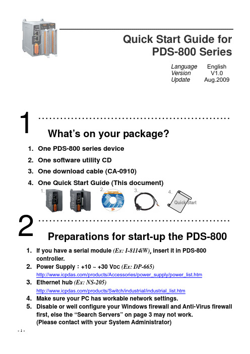
Quick Start Guide forPDS-800 SeriesLanguage EnglishVersion V1.0Update Aug.2009……………………………………………..What’s on your package?1. One PDS-800 series device2. One software utility CD3. One download cable (CA-0910)4. One Quick Start Guide (This document)……………………………………………..Preparations for start-up the PDS-8001. If you have a serial module (Ex: I-8114iW),insert it in PDS-800 controller.2. Power Supply:+10 ~ +30 V DC (Ex: DP-665)/products/Accessories/power_supply/power_list.htm3. Ethernet hub (Ex: NS-205)/products/Switch/industrial/industrial_list.htm4. Make sure your PC has workable network settings.5. Disable or well configure your Windows firewall and Anti-Virus firewallfirst, else the “Search Servers” on page 3 may not work.(Please contact with your System Administrator)123.2.1.Quick Start4.PDS-811PDS-8211. Connect both the PDS-800 controller and your computer to the samesub network or the same Ethernet Switch.2. Short the RxD and TxD pins of the PDS-800 controller for self-test.3. Short the TxD1 (Pin 19) and RxD1 (Pin 37) pins of the 4-Port I-8114iWmodule for example of self-test.4. Supply +24 V DC (+10 ~ +30 V DC ) power to the PDS-800 controller.………………………………………….....Installing VxComm Utility on your PCThe software is located at :CD: \NAPDOS\Driver\VxComm_Driver pub/cd/8000cd/napdos/driver/vxcomm_driver/4Ethernet SwitchHost PC1.Power supply(10 ~ 30 V DC )4.Optional Serial Module+Vs 3.Short12037 RxD119 TxD11. Execute the VxComm Utility and then search your PDS-800 controller.2. Double click the name of the PDS-800 to open the Configure Serverdialog box.3. Contact your Network Administrator to obtain a correct networkconfiguration (such as IP/Mask/Gateway). Enter the network settingsand then click “OK”. The PDS-800 controller will be restarted itself immediately.……………………………………………..Configuring Virtual COM Ports1. Click the "Search Servers" button again to search PDS-800 to ensurethe new configuration of PDS-800 is working well. Then click your PDS-800 on the list to select it.2. Click the “Add Server [s]” button. Assign a COM Port number andclick “OK” to save your settings.645Assign a COM Port number13. Click on PDS-800 name or slot that your module plugged in, and thencheck the Virtual COM port numbers on the PC.Click your PDS-800 or4. Click “Tools” >> “Restart Driver” , and then click the “RestartDriver” button to start the driver.Click thebutton to start the driver……………………………………………..Testing your PDS-8001. Right click Port 1 and then choose the “Open COM Port” item.2. Check that the configuration of the COM Port is correct and then clickthe “Open COM” button.72Right ClickCheck that the configuration is correct and then click the “Open COM” button43. Type a string in the send field then click the “Send” button.If a response is received, it will be displayed in the received field.……………………………………………..Testing your serial modules (Optional)1. Click “Slot 1” and right click Port 10 and then choose the “Open COMPort” option. (Such as Sec.7-1, P6)2. Check that the configuration of the COM Port is correct and then clickthe “Open COM” button. (Such as Sec.7-2, P6)3. Type a string in the send field then click the “Send” button. Checkwhether the response is the same with the string sent or not. (Such as Sec.7-3, P7)4. If the test is successful, other COM port programs will be able to workdirectly with using the Virtual COM Port.5. While using RS-485 modules (Ex: I-8144iW), you should wire theData1+ with Data2+ signals, and wire the Data1- with Data2- signals for self-test. Then open the first two COM ports, send data to one and receive data from the other.8CompleteThe response is displayed6……………………………………………..Additional Information¾ PDS-800 Series Product page:/products/Industrial/pds/pds-8x1.htm¾ PDS-800 Documentations :CD:\Napdos\pds\pds-8x1\document\/pub/cd/8000cd/napdos/pds/pds-8x1/document/¾ PDS-800 firmware :CD:\Napdos\pds\pds-8x1\vxcomm\server(pds)\/pub/cd/8000cd/napdos/pds/pds-8x1/vxcomm/server(pds)/ICP DAS Web SiteContact Us******************Copyright ©2009 by ICP DAS Co., Ltd. All right are reserved9。
- 1、下载文档前请自行甄别文档内容的完整性,平台不提供额外的编辑、内容补充、找答案等附加服务。
- 2、"仅部分预览"的文档,不可在线预览部分如存在完整性等问题,可反馈申请退款(可完整预览的文档不适用该条件!)。
- 3、如文档侵犯您的权益,请联系客服反馈,我们会尽快为您处理(人工客服工作时间:9:00-18:30)。
图 8 变送器与接头法兰连接 图 9 变送器与三阀组连接 2.5.3 导压管的装配 (1) 系统引压口
R ≤ U − 10.5 (Ω)-------------------------------------------公式 1
0.023
在本安回路中,R 应包含安全栅电阻。 在需要 HART 通信的变送器回路中,230≤R≤500,15.8≤U≤45。 变送器电源负载关系如图 5(阴影部分为正常工作区)。
变送器的铭牌如图 1。
R PDS 智能压力变送器 渝 00000334号
PDS Q/CY 435-
HART 4~20 mAd.c.
24 Vd.c.
重庆川仪总厂有限公司控制仪表分公司 中国 重庆 北部新区 黄山大道中段61号
图 1 PDS 变送器铭牌 2.3 电气连接
警告 防爆型变送器的电气安装连接必须严格遵循国家相关标准的规 定;隔爆型变送器必须切断电源后方可旋开盲盖接线,接线完成 后应将盲盖旋紧并用防爆锁紧螺钉锁紧,避免盲盖被随意旋开。 小心 变送器电源(信号)线的敷设应满足以下要求: 电缆的选用应考虑机械性能、绝缘强度、现场干扰、环境温度、 环境腐蚀等因素; 与电压>60V 的线缆隔离; 避开附近大功率电气设备,使用屏蔽电缆(屏蔽层双端接地良好)。 2.3.1 接线腔连接 变送器采用二线制传输,信号线即电源线,与外部电源的连接示意图 如图 2。
力变送器。变送器采用西门子原装的传感器和电子部件,内含西门子的温 度补偿、线性补偿技术,具备智能化和通信功能,可广泛应用于石油、化 工、冶金、电站等行业中。
1.2 标识说明 说明书中较多地采用了一些标识,分别说明如下: 警告 表示危险,可能导致重大人身事故或重大财产损失。 小心 表示一般故障,可能导致轻度人身伤害或一定财产损失。 提示 关于产品的重要信息,或手册中某一部分内容需要提示。
现场安装管的方式,安装管直径Φ50ÆΦ60mm,安装板与变送器用螺钉连
接,装配力矩 40N.m。
图 12 垂直配管安装方式 提示 变送器安装后,正负引压口应尽可能在同一水平面上。
1 前言
感谢您选用 PDS 系列智能差压/压力变送器。
在安装使用前,请详尽阅读本说明书,以便本仪表能安全高效地应用 于您的工程项目中。为了保证操作人员、仪表和系统的安全,请关注用户 手册中带有警示标识的语句,严格按照国家和行业相关标准、安全操作规 则操作。
1.1 概述 PDS 系列变送器是重庆川仪选用西门子散件生产的一种高性能差压/压
2 安装与启用
2.1 环境条件 2.2 产品验收 2.3 电气连接 2.4 通信连接 2.5 压力过程连接 2.6 变送器的启用
3 本机设定
3.1 总体说明 3.2 LCD 显示窗 3.3 按键操作 3.4 盲操作
4 HART 功能
4.1 HART 基本功能 4.2 基本信息 4.3 快速响应模式 4.4 设定电流限值
变送器的外形尺寸如图6
图 6 变送器外形尺寸图 小心 进行压力过程连接之前,请确认相关管路通畅,相关结构件强度
足够;进行压力过程连接时,请确认相关阀门已关闭;连接完成 后,请确认连接部分介质密封性良好;在需要排气排液时,应采 取相应的安全措施,避免高压或腐蚀介质造成人身伤害及财产损 失。 2.5.1 变送器的测量部 变送器的测量部由膜盒、容室法兰、排气排液塞、螺栓螺母等零件组 成。变送器的安装、压力过程连接、现场压力的引入都在这一部分。
警告 对隔爆型变送器,上电时严禁拧开视镜盖旋转显示器。 2.3.5 接地 变送器上有内接地和外接地,两处均有接地标识,可任选其一或两处 接地,接地电阻≤100Ω。 2.3.6 电源电压与负载电阻
变送器的电源电压 U(单位 V)的范围:10.5≤U≤45 变送器回路的负载电阻 R(单位Ω)应满足公式 1 的要求。
变送器使用安装管加支架的安装方式,安装管直径要求Φ50ÆΦ60mm, 先将安装板用U型螺栓固定在安装管上,然后将变送器用四颗螺钉固定在安 装板上。如果操作不便,也可先连接变送器与安装板,再连接到安装管。 变送器的安装板可适应多种安装管的位置,但原则上,变送器安装完成后, 正负引压口应处于同一水平线上。
2.1.3 电磁环境条件 1) 磁场强度:≤400A/m 2) 射频干扰:≤3V/m(80MHzÆ1GHz) 3) 静电干扰: ≤8000V 4) 电快速瞬变脉冲群干扰:≤2000V(5kHz)
2.2 产品的验收 变送器安装使用前,请按订货合同验收,核对规格、型号、量程范围、
位号等信息是否正确;检查安装板、U 型螺栓、螺母、垫圈、说明书、合格 证等附件是否齐备。
压力管道内的沉淀物、残液等进入导压管,将导致压力测量时产生误 差。要排除这些影响,应按图 10 所示的角度范围安装引压阀。
过程介质为液体时,引压口水平或水平之下 45°之内; 过程介质为气体时,引压口垂直向上或与垂直向上呈 45°角之内; 过程介质为蒸汽时,引压口水平或水平之上 45°之内。
图 10 引压口的位置
变送器与外界的电气连接结构示意图如图 3。
图 3 电气连接结构示意图 在变送器配线口与金属软管接头的螺纹上涂防水用的非硬化密封剂, 使用 600V 规格 PVC 绝缘电缆线或与之规格相当的电缆。 对于普通型或本安型变送器,使用金属套管或防水套管。 对于隔爆型变送器,必须使用符合隔爆要求的隔爆密封接头及其它连 接件,电缆直径Φ8.5±0.5mm。 2.3.3 电子室旋转 变送器的电子室可顺时针或逆时针旋转,但为了电子室内的连接安全, 旋转有一定的角度限制。如图 4 所示,壳体与测量部连接的颈部有两片阴 影部分区域,测量部的颈部有“旋转定位标识”,壳体与测量部的相对旋转 在“旋转定位标识”指向阴影部分之内均可,可旋转的总角度 270°(旋转
2 安装和启用
2.1 环境条件 变送器的安装环境应满足以下条件:
2.1.1 自然环境条件 1) 环境温度:-40Æ+85℃ (防爆变送器 T5 温度组别最高+70℃、T6 温度组别最高+60℃) 2) 介质温度:-40Æ+100℃ 3) 相对湿度:≤95% 4) 大气压:86Æ106kPa
2.1.2 机械环境条件 振动加速度:≤2g
用户手册 user’s manual
PDS 智能变送器
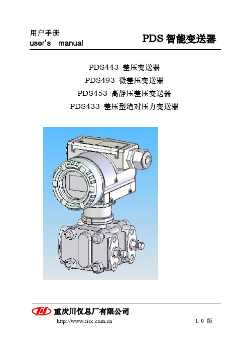
PDS443 差压变送器 PDS493 微差压变送器 PDS453 高静压差压变送器 PDS433 差压型绝对压力变送器
重庆川仪总厂有限公司
1.0 版
目录 1 前言
1.1 概述 1.2 标识说明 1.3 版本说明 1.4 品质保证
导压管应垂直或倾斜排布,即使水平排布,也应有适度的倾斜,使过 程介质不会残留在管道内。 (2) 变送器的位置
过程介质为液体或蒸汽时,原则上变送器的位置低于引压阀; 过程介质为气体时,原则上变送器的位置高于引压阀。 (3) 温差、冷凝、防冻、防风 配管时应尽量使两导压管不产生温差,因为温差会引起介质密度的变 化,导致测量误差。 测量蒸汽介质时,导压管内的液体因过程温度或环境的变化而反复凝 结、蒸发,会使高低侧分别产生液柱,液柱的高度不同将为测量带来误差, 因此,蒸汽测量时请使用冷凝槽。 应采取适当的措施,防止变送器及导压管内的过程流体发生冻结。凝 固的介质可能会损坏传压膜片。 用差压变送器测量微压时,低压侧应有稳定的参考压力。如果参考压 力为大气,需要保证无风,此时可将变送器置于箱内或将低压侧引入防风 盒内。 2.5.4 水平配管安装方式
图 5 电源负载图 2.4 通信连接
变送器的通信方式有 HART 和 PROFIBUS 两种,这里对 HART 型变送 器的通信连接作简要介绍。
HART 型变送器的输出在 4Æ20mA 信号的基础上调制了 HART 数字信 号。HART 信号以 2200Hz 表示“0”,以 1200Hz 表示“1”,数字信号直流 平均值为 0,对 4Æ20mA 回路不产生影响。
在图 2 所示变送器与外部电源连接示意图中,HART 终端设备可跨接
在变送器的“+”、“-”端,也可跨接在负载电阻的两端。变送器可与系统 中所有 HART 类仪表如执行器、阀门定位器等配合使用,系统中可同时存 在 16 台 HART 仪器,使用 HART 终端设备可分别对它们进行操作。图 5 表达了 HART 信号可使用的电源负载区域。 2.5 压力过程连接
1.3 版本说明 z 版权所有,未经重庆川仪书面许可,本说明书不能以任何形式修改、
复制、截取。 z 本说明书作为产品附件与产品同时送达使用者手中。 z 请使用当前版本的说明书,不保证其它版本说明书能在当前产品中
正常使用,除非另有说明。 z 本说明书中如有错误、遗漏或不可理解之处,请联系重庆川仪。 z 对于用户特殊订货仪表,本说明书不完全适用,可作附加说明。 1.4 品质保证 z 质保期限根据报价书指定,或由双方在合同中特殊说明。保修期内
4.5 传感器限值调整 4.6 参考电流微调 4.7 返回出厂设置 4.8 智能自诊断 4.9 模拟仿真
5 技术规范
5.1 功能规范 5.2 性能规范 5.3 物理规范
6 维护与维修
6.1 运输与贮存 6.2 校验设备 6.3 常规维护 6.2 微差压变送器 7.3 高静压差压变送器 7.4 差压型绝对压力变送器 7.5 型谱附加选项
时,“旋转定位标识”不可经过非阴影区域)。具体方法为:松开外壳紧固 螺钉,根据现场的安装要求旋转,完成后拧紧外壳紧固螺钉。
图 4 电子室旋转 2.3.4 LCD 显示器旋转
变送器可选配 LCD 显示器,安装在外壳与视镜盖内。变送器现场安装 完成后,可改变显示器的显示方向。操作方法为:旋开视镜盖,用工具卸 下显示器安装螺钉,取下显示器,按需要改变方向(4 个方向,每 90 度一 个位置)。
