双轴跟踪说明书
太阳能双轴跟踪说明书

全方位太阳能跟踪发电研究仪
说明书
【概述】
太阳能跟踪发电研究仪是一款自动追踪太阳光的实验研究仪,它能够最大限度的采集太阳光,并将太阳能转化为电能,储存在蓄电池中。
可以通过本实验仪观察太阳能电池板的电流,电压,功率,温度,以及太阳光与水平面的夹角。
还可外接无线收发装置,远程监控。
本仪器曾获得过多项国家专利。
专利号:
【适用范围】
太阳能路灯(交通灯)
太阳能实验仪
太阳能演示仪
家用太阳能发电
其他一些太阳能追踪设备
【功能特点】
【仪器面板】
一正面
1.功率表
2.电压表
3.电流表
4.温度表
5.角度开关--按下:开启数码管显示弹起:关闭数码管显示
6.电压表,电流表,功率表开关----按下;开启三表显示弹起;关闭三表显示
7.led指示灯----按下开启led灯条弹起关闭led灯条
8.充电选择开关-----按下给蓄电池充电弹起断开蓄电池连接
9.工作模式显示H 正常工作 4 休眠
10.11.角度的数码显示最小精度为1度
12.led灯柱----用于指示太阳光强度(改变太阳光强度亮不同的灯)
13.led灯柱----用于指示与太阳光与电池板的夹角量
14.摇杆----用于手动调节太阳能电池板,设置水平,长按可以将角度致零,同时也是自动转手动的开启按键之一,同时还需要按下16
15.工作状态选择按键-----H正常工作4休眠模式
16.自动手动切换按键切换时需要和14同时使用(按下)
二反面。
光伏双轴跟踪装置

光伏双轴跟踪装置说明书摘要一种光伏双轴跟踪装置,主要内容为:水平电机固定安装在水平蜗轮蜗杆减速器上,而水平蜗轮蜗杆减速器固定安装在水平壳体上,水平蜗轮蜗杆减速器输出轴通过水平联轴器与水平小齿轮轴连接,水平大齿轮与水平小齿轮啮合带动水平大齿轮轴的转动,来调整太阳能电池板在经度方向上的跟踪;竖直电机固定安装在竖直蜗轮蜗杆减速器上,而竖直蜗轮蜗杆减速器固定安装在竖直壳体上,竖直蜗轮蜗杆减速器输出轴通过竖直联轴器与竖直小齿轮轴连接,竖直大齿轮与竖直小齿轮啮合带动竖直轴的转动,来调整太阳能电池板在纬度方向上的跟踪。
本装置可在经度和纬度方向上进行调整,使其与太阳光线时刻保持垂直,提高了光伏发电装置的发电能力。
摘要附图12345678910111213141516171819202122权利要求书1.一种光伏双轴跟踪机构,其特征在于,该系统包括水平电机(10)固定安装在水平蜗轮蜗杆减速器(9)上,而水平蜗轮蜗杆减速器(9)固定安装在水平下壳体(11)上,水平蜗轮蜗杆减速器(9)输出轴通过水平联轴器(8)与水平小齿轮轴(3)连接,水平大齿轮(5)与水平小齿轮(6)啮合带动水平大齿轮轴(2)的转动,水平大齿轮轴(2)、水平小齿轮轴(3)采用水平轴承(4)支撑,来调整太阳能电池板(1)在经度方向上的跟踪;竖直电机(13)固定安装在竖直蜗轮蜗杆减速器(14)上,而竖直蜗轮蜗杆减速器(14)固定安装在竖直壳体(19)上,竖直蜗轮蜗杆减速器(14)输出轴通过竖直联轴器(15)与竖直小齿轮轴(16)连接,竖直大齿轮(18)与竖直小齿轮(17)啮合带动竖直轴(12)的转动,竖直轴(12)、竖直小齿轮轴(17)采用竖直轴承(20)支撑,来调整太阳能电池板(1)在纬度方向上的跟踪。
2.如权利要求1所述的一种光伏双轴跟踪机构,其特征在于采用水平涡轮蜗杆减速器(9)带动水平齿轮传动副(5,6)实现水平方向高的传动比,竖直涡轮蜗杆减速器(14)带动竖直齿轮传动副(17,18)实现竖直方向高的传动比。
双轴说明书
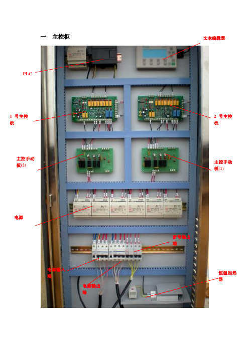
一主控柜PLC文本编辑器1号主控板2号主控板主控手动板(2)主控手动板(1) 电源电源输入端电源输出端信号输出端恒温加热器1.文本编辑器操作说明使用 TD400C,可以查看、监视和更改您应用程序固有的过程变量。
使操作员或用户能够与应用程序进行交互。
TD400C设备是一种小型紧凑型设备,为与S7-200 CPU 进行界面连接提供了必需的组件。
1在TD400C启动后会显示的页面是:2 各功能键的作用F1:启动自动跟踪状态,当前的方位角,高度角会跟踪上太阳当时的方位角及高度角。
SHIFT+F1: 停止自动跟踪(处于手动控制状态)F2: 按下F2跟踪支架往东转。
(SHIFT+F2停止)F3:按下F3跟踪支架往西转。
(SHIFT+F3停止)F5:按下F5跟踪支架往上转。
(SHIFT+F5停止)SHIFT+F4:当前方位角与高度角都变成0度(基准角度)F6:按下F6跟踪支架往下转。
(SHIFT+F6停止)a)F8:按F8, 输入密码1234会出现如下画面:按ENTER选择要修改的那一栏(按至最后一行会自动换页),选中那一栏后按左右移动键移动光标位置,移到对应的位置后按上下箭头键选择你需要的数据。
显示精度,实际风速,高风速设定,正常风速设定。
实际风速在大于高风速并持续一分钟后跟踪停止,当风速减小到小于正常风速并持续一分钟,恢复跟踪。
b)ESC:按ESC会出现如下画面:可以修改时间(所用的时间为世界时间),系统菜单语言等等。
c)夜返当高度角为90度时开始夜返,返回到基准角度(即方位角0度,高度角0度)。
主控板主控板(1)对应手动主控板(1)控制跟踪支架的方位角方向一号主手控板控制东西方向,(K1)开关在 “M ”位置时,(LEW )亮起东西方向的自动信号被切断,此时处于手动状态。
当(K1)(K2)号开关同时处在“M ”位置时(LEW )(LE )亮起,输出手动向东转的信号。
当(K1)(K3)号开关处在“M ”位置时,(LEW)(LM )亮起,输出手动向西转的信号。
Meade LX70双轴电子驱动器操作说明说明书

Operating Instructions for the Meade LX70 Dual Axis Motor DriveThe Meade LX70 Dual Axis Motor Drive allows electronic tracking of night sky objects at the sidereal rate and electronic control through a keypad. The Dual Axis Motor Drive is essential for users wanting electronic RA tracking capabilities on their Meade LX70 and those interested in beginning astro-photography. In addition, the Dual Axis Motor Drive gives elec-tronic control of both axes enabling fi ne slow motion slewing control to the user through a keypad. For both the novice user and budding astro-photographer, use of the optional Meade #670010 Polar scope is recommended.Before beginning the below installation procedure it’s recommended to remove the optical tube and counterweight from the mount. When completed, reinstall the optical tube and counterweight, then perform a polar alignment on the night sky as described in your mount’s user manual.Tools Needed:• Phillips screw driver • 4 mm hex wrench • 2 mm hex wrench • 5 mm hex wrench Installing the RA motor drive1. Remove both front and rear latitude adjustment knobs on the LX70 mount so the mount head can pivot its full range of motion. See Figure2.2. Remove the RA motor cover by removing the small Philips screw located on the bottom side of the cover. Set the motorcover and Philips screw aside. See Figure 3.3. Using your hand or slow motion control cable, rotate theRA worm shaft until the fl at portion at the shaft end faces in the direction of the front north tripod leg. See Figure 4.4. Attach the brass spur gear assembly onto the shaft on the left side of the mount and secure with the 2mm hexwrench. The setscrew must be tightened against the fl atsurface on the shaft end. See Figure 4.5. Pivot the mount head downward until it stops. This will be at a latitude scale reading near 25°.6. Using the 4mm hex key and 35mm long screw, insert the long screw into the mount as shown in Fig 6. Use the hexkey to hold the screw in place.7. Place the RA motor assembly onto the mounting plate lo-cated on the front of the mount. The mounting plate should be positioned so the brass gears align and mesh well with each other. See Figure 7 & 8. 8. Using the 4mm hex key and 35mm long screw, securethe RA motor in place. See Figure 6 & 7.9. Pivot the mount head upward until it stops. This will be at a latitude scale reading near 60°.Figure 6Figure 4Figure 5Figure 7Figure 1Batterybox DEC Motor Assembly RA Motor Assembly 35mm longscrew Hand Controller RA & DEC Spur Gears 2mm wrench 5mm wrench 4mm wrenchScrewdriver15mm longscrewFigure 2RemoveRemove Figure 3Remove screw, then motor coverInstall spur gearonto shaft Use 2mm wrenchto tightenInstall 35mm screw into mountInstall RA MotorAssembly10. If desired, remove the black plastic oval on the RA motor cover side and slide the RA motor cover back onto the mount. Secure in place with the Philips screw.11. The RA slow motion control cable and latitude adjustment knobs that came with the mount can now be secured as described in the LX70 instructional manual. See Figure 9.Installing the DEC motor drive1. Using your hand or slow motion control cable, rotate the DEC worm shaft until the fl at portion at the shaft end faces outward. See Figure 10.2. Attach the brass spur gear onto the longer DEC worm shaft and secure with the 2mm hex wrench. The setscrew must be tightened against the fl at surface on the shaft end. See Figure 10.3. Place the Dec motor assembly against its mounting plate and insert the 15mm long hex screw on the top side hole lightly securing the motor assembly in place using the 5mm hex wrench. See Figure 11. Adjust the motor assembly until the two brass gears are aligned before fi rmly tightening the screw. See Figure 8 & 12.4. The DEC slow motion control cable that came with the mount can now be secured as described in the LX70 instruc-tional manual. See Figure 13.Connecting the hand controller1. Locate the hand controller and note the two cables at the bottom. Connect the cable labeled DEC to the connector at-tached to the DEC motor assembly. See Figure 14.2. Connect the cable labeled RA to the RA motor assembly by inserting the cable thru the hole on the bottom side of the RA motor cover. See Figure 15.3. Next connect the cable attached to the battery holder to the hand box port labeled 6V DC Power. See Figure ing the motor drive & hand controller (Reference Figure 16)The Meade LX70 Dual Axis Motor drive requires 4 “D” size batteries. Begin by installing the batteries into the battery box and note the correct polarity markings shown in the battery holder. If not already connected, connect the battery box to the hand controller port labeled 6V DC Power. See Figure 16.Figur e 8Figure 9Figure 10Figure 11Figure 13Ensure proper gear meshInstall RA Slow Motion Control CableInstall spur gear onto shaftInsert 15mm screwInstall DEC Slow Motion Control CableFigure 15Connect RA Hand Controller CableFigure 14Connect DEC Hand Controller CableTo turn on the motor drive, users in the northern hemisphere should slide the on/off switch to “N”. Users in the southern hemisphere should slide the on/off switch to “S”. When the drive is powered, a green LED will illuminate on the hand con-troller and the RA motor will begin to turn slowly.NOTE: The DEC motor will not move until commanded by the hand controller.When the battery power gets low, the LED will begin to fl ash indicating they should be replaced. A set of new alkaline bat-teries should last several nights of observing under normal conditions.T o use the motor drive to its fullest potential a proper polar alignment on the night sky is needed. Follow the instructions in your LX70 mount manual to perform this alignment. If using the optional Meade #670010 polar scope, follow the included instructions. Once the telescope is accurately polar aligned, the dual axis motor drive can be used to track night sky ob-jects at the sidereal rate.With the motor drive installed, each axis can be engaged/disengaged from the motors by locking/unlocking the friction clutch. T urn the clutch knob clockwise to engage the motor drive and allow the hand controller to control each axis. See Figure 18.NOTE: When the motor drive clutch is engaged, the slow motion control cables cannot be used.T urn the clutch knob counter-clockwise to disengage the motor drive system and allow the slow motion control knobs to move the axis. When use of the slow motion control cable is complete, re-engage the drive clutch by turning the clutch knob clockwise.T o move the mount using the hand controller, lock both mount RA and Dec locks and motor drive clutch knobs for each axis. See Figure 18 & 19. Then select the desired motor speed on the hand controller using the switch labeled 2X-4X-8X at the top of the hand controller. See Figure 16. Press and hold the direction button desired. When the motor is being driven, a red LED will illuminate on the hand controller.Note the following motor speeds:• 2X sidereal speed will drive the mount at 1/2° per minute.• 4X sidereal speed will drive the mount at 1° per minute.• 8X sidereal speed will drive the mount at 2° per minute.Locate night sky objects by moving the mount as described in the LX70 instructional manual. Unlock the RA and DECFigure 16Figure 18Figure 19Tighten Drive Clutch Knobto engage gears and usehand controllerFigure 17Dual AxisMotor DriveinstalledMountDECLockMountRALockDec MotorAssemblyRA MotorAssemblybehindcoverBattery BoxHandControllerRA DriveClutch KnobDEC Slow motioncontrol cableRA Slow motioncontrol cableDECMotorCableRAMotorCableDEC Drive ClutchKnob (not visible)27 Hubble, Irvine, California 92618(800) 626-3233 © 2015 Meade Instruments Corp. reserves the right to change product speci fi cations or to discon-tinue product without notice. 14-9294-00 Rev 2.Locks (see Figure 19) and locate the desired target, then re-lock the RA and DEC locks. If desired, the drive clutches(see Figure 18) can be disengaged and slow motion control cables used to center the target. When centered, lock the drive clutches(see Figure 18) and the RA drive will follow the object as it moves at the sidereal rate across the sky. Note: The tracking performance is dependent on how accurately the mount is polar aligned on the celestial pole.Note:•The RA & Dec mount lock levers must be locked for the slow-motion controls(see Figure 17) or drive motors to operate.•The RA/DEC motor drive clutch knobs must be tight for the motors to operate and loose for the slow motion controls to operate. See Figure 18.The hand controller LED will illuminate, displaying the following information.• Solid LED - Motor drive running.• No LED - No Power; unit is off or power cable is disconnected. Verify correct battery polarity.• Blinking LED - Battery power is low. Replace batteries.RECYCLING INFORMATION Correct Disposal of this Product(Waste Electrical & Electronic Equipment - EU Countries only)This marking shown on the product or its literature indicates that it must not be disposed of in unsorted municipal waste at the end of its working life To prevent possible harm to the environment or human health from uncontrolled waste disposal, please separate this from other types of wastes and recycle it as required by law. Household users should contact either the retailer where they purchased this product, or their local government of fi ce, for details of where and how they can take this item for environmentally safe recycling. Business users should contact their supplier and check the terms and condi-tions of the purchase contract. This product should not be mixed with other commercial wastes for disposal.Meade Customer ServiceIf you have a question concerning your LX70 dual axis motor drive, contact the Meade Instruments Customer Service Department at (800) 626-3233.Customer Service hours are 7:00 AM to 5:00 PM, Paci fi c Time, Monday through Friday. In the unlikely event that your LX70 dual axis motor drive requires factory servicing or repairs, write or call the Meade Customer Service Department fi rst, before returning the telescope to the factory, giving full particulars as to the nature of the problem, as well as your name, address, and daytime telephone number. The great majority of servicing issues can be resolved by telephone, avoiding return of the telescope to the factory. If factory service is required, you will be assigned a Return Goods Authori-zation (RGA) number prior to return.MEADE LIMITED WARRANTYEvery Meade telescope, and telescope accessory is warranted by Meade Instruments Corp. (“Meade”) to be free of defects in materials and workmanship for a period of ONE YEAR from the date of original purchase in the U.S.A. and Canada. Meade will repair or replace a product, or part thereof, found by Meade to be defective, provided the defective part is returned to Meade, freight-prepaid, with proof of purchase. This warranty applies to the original purchaser only and is non-transferable. Meade products purchased outside North America are not included in this warranty, but are covered under separate warranties issued by Meade international distributors.RGA Number Required: Prior to the return of any product or part, a Return Goods Authorization (RGA) number must be obtained from Meade by writing, or calling (800) 626-3233. Each returned part or product must include a written statement detailing the nature of the claimed defect, as well as the owner’s name, address, and phone number.This warranty is not valid in cases where the product has been abused or mishandled, where unauthorized repairs have been attempted or performed, or where depreciation of the product is due to normal wear-and-tear. Meade speci fi cally disclaims special, indirect, or consequential damages or lost pro fi t which may result from a breach of this warranty. Any implied warranties which cannot be disclaimed are hereby limited to a term of one year from the date of original retail pur-chase. This warranty gives you speci fi c rights. Y ou may have other rights which vary from state to state. Meade reserves the right to change product speci fi cations or to discontinue products without notice.。
太阳能双轴跟踪控制系统工作流程

太阳能双轴跟踪控制系统工作流程太阳能是一种清洁、可再生的能源,近年来得到了广泛的应用。
然而,由于太阳能的收集效率与太阳的位置有关,因此需要使用太阳能跟踪系统来提高太阳能的收集效率。
太阳能双轴跟踪控制系统是一种高效的太阳能跟踪系统,下面将介绍该系统的工作流程。
一、系统结构太阳能双轴跟踪控制系统由以下几部分组成:1. 太阳能电池板:用于收集太阳能供电。
2. 电机和减速器:用于控制太阳能电池板的运动。
3. 传感器:用于检测太阳的位置和太阳能电池板的位置。
4. 控制器:用于控制电机和减速器的运动,使太阳能电池板始终面向太阳并跟随太阳运动。
二、系统工作原理太阳能双轴跟踪控制系统的工作原理如下:1. 传感器检测到太阳的位置。
2. 控制器接收传感器的信号,并计算出太阳能电池板需要转动的角度和方向。
3. 控制器控制电机和减速器的运动,使太阳能电池板始终面向太阳并跟随太阳运动。
4. 传感器不断检测太阳的位置,并向控制器发送信号,控制器根据信号调整太阳能电池板的位置。
5. 太阳能电池板始终面向太阳并跟随太阳运动,从而提高太阳能的收集效率。
三、系统优点太阳能双轴跟踪控制系统具有以下优点:1. 收集效率高:太阳能双轴跟踪控制系统可以使太阳能电池板始终面向太阳并跟随太阳运动,从而提高太阳能的收集效率。
2. 稳定性强:太阳能双轴跟踪控制系统可以根据传感器检测到的太阳位置进行实时调整,保证太阳能电池板始终面向太阳并跟随太阳运动,从而保证系统的稳定性。
3. 适应性强:太阳能双轴跟踪控制系统可以适应不同的地理位置和气候条件,从而适用范围广。
4. 节能环保:太阳能双轴跟踪控制系统使用太阳能作为能源,不产生污染物,具有良好的节能环保效果。
四、系统应用太阳能双轴跟踪控制系统可以广泛应用于太阳能发电、太阳能光热利用等领域。
例如,在太阳能发电中,太阳能双轴跟踪控制系统可以提高太阳能电池板的收集效率,从而提高发电量;在太阳能光热利用中,太阳能双轴跟踪控制系统可以调整太阳能集热器的位置,从而提高集热效率。
太阳能双轴追踪技术规范书

漯河职业技术学院分布式并网型光伏发电一期工程双轴追踪成套支架与弧形成套支架招标文件(技术规范书)招标人:投标人:设计人:河南大地电力勘察设计有限公司2015年12月目录1、总则 (1)2、工程概况 (2)2.1工程项目名称 (2)2.2工程项目地点 (2)2.3项目规模 (2)2.4工程建设条件 (2)2.5电站工程主要建设方案 (3)3、太阳能电池组件供应技术规范 (5)3.1设计和运行条件 (5)3.2规范和标准 (5)3.3技术要求 (7)3.4包装 (10)3.5数性表(投标人细化填写) (11)4、太阳能电池组件供应附录 (12)附录1技术差异表 (12)附录2供货范围 (13)附录3技术资料 (15)附录4技术服务 (16)附录5投标人需要说明的其他技术问题 (18)1、总则1)本技术规范书适用于漯河职业技术学院分布式并网型光伏发电一期工程的双轴追踪成套支架与弧形成套支架,包括双轴追踪成套支架及其辅助材料的功能、性能、结构等方面的技术要求。
2)本技术规范书提出了最低限度的技术要求,并未规定所有的技术要求和适用的标准,投标人应提供一套满足招标文件和本技术规范书所列标准要求的高质量产品。
3)投标产品如与本技术规范书有偏差(无论多少或微小)都必须清楚地表示在投标文件的“差异表”中,否则招标人将认为投标人完全接受和同意本技术规范书的要求。
4)本技术规范书所使用的标准如与投标人所执行的标准发生矛盾时,按较高标准执行。
5)在签订合同之后,招标人保留对本技术规范书提出补充要求和修改的权利,投标人应予以配合。
如招标人提出修改,招标人与投标人应召开设计联络会,具体由招标人、投标人双方协商确定。
6)中标后投标人应协同设计方完成深化方案设计,配合施工图设计,系统调试和验收,并承担培训及其它附带服务。
7)本技术规范书经双方签字认可后作为订货合同的附件,与合同正文具有同等效力。
2、工程概况2.1工程项目名称漯河职业技术学院分布式并网型光伏发电一期工程2.2工程项目地点漯河职业技术学院光伏屋顶光伏并网发电项目位于河南省漯河市源汇区大学路,经度:东经114°,维度:北纬33°56',项目地址北接许昌,南临驻马店,西邻平顶山、东临周口,地处淮河上游的平原地区,属暖温带南部边缘。
矢量双轴跟踪光伏支架说明书

矢量双轴跟踪光伏支架说明书矢量双轴跟踪光伏支架是一种高效的太阳能电池板支架,它可以自动调整太阳能电池板的角度,以获得更高的光能利用效率。
本说明书将详细介绍矢量双轴跟踪光伏支架的组成、安装、操作和维护。
一、组成矢量双轴跟踪光伏支架主要由以下部分组成:1. 支架脚:支撑整个支架系统的基础,需要固定在地面或者水泥基础上。
2. 支架柱:支撑悬挂在上面的太阳能电池板,通常由金属材料制成,具有很强的承重能力和稳定性。
3. 滑轨:支持太阳能电池板上下左右的移动,采用钢制材料,具有耐腐蚀和耐磨损的特性。
4. 电机:控制太阳能电池板上下左右的移动,使用直流电机,并配备马达控制器,以确保精确的位置控制。
5. 传感器:感应太阳的位置和光线强度,帮助控制单元确定太阳能电池板的位置,并调整电机的运行。
6. 支架交流电源:为电机提供必要的电力,供电电压一般为110V或者220V。
二、安装1. 选择适当的安装位置:矢量双轴跟踪光伏支架的安装位置应该是避免被阴影遮挡的位置。
建议将其安装在地面平整的位置。
2. 安装支架脚:根据土地情况和支架重量选择合适的基础,固定支架脚到地面或者水泥基础上。
3. 安装柱体:将支架柱安装到支架脚上,并使用螺栓进行拧紧。
4. 安装滑轨:使用螺栓将滑轨安装到支架柱的顶部,然后将太阳能电池板安装到滑轨上。
5. 安装电机和传感器:将电机和传感器安装在支架柱的顶部,并使用螺栓进行拧紧。
6. 连接电源和控制器:将支架交流电源与电机和传感器连接,然后连接控制单元。
7. 调整支架角度:通过控制单元调整支架角度,直到太阳能电池板获得最大光能利用效率。
三、操作和维护1. 操作:矢量双轴跟踪光伏支架通过控制单元自动调整太阳能电池板的角度,不需要手动干预。
使用时只需要保证电源供应稳定即可。
2. 维护:每年需要对矢量双轴跟踪光伏支架进行一次维护,检查所有部件是否正常工作,清除积尘和腐蚀物,并进行必要的维修和更换。
如果控制器出现问题,可以联系售后服务人员进行维修。
天健机械手双轴说明书

天健机械手双轴说明书
1.机械手的手动控制过程
在进行自动运行前先检查PLC控制程序,确定无误后,启动机械手进行回零,然后:上升—动作是否完成,行程开关是否实现到限制行程的的功能,对应的指示灯是否正常工作。
机械手臂右行—动作是否完成,行程开关是否实现到限制行程的的功能,对应的指示灯是否正常工作。
机械手臂下降—动作是否完成,行程开关是否实现到限制行程的的功能,对应的指示灯是否正常工作。
吸盘吸紧工件—动作是否完成(是否将工件吸起),光电开关是否实现到限制行程的的功能,对应的指示灯是否正常工作。
2.机械手自动运行控制过程
在进行自动运行前先检查PLC控制程序,确定无误后,启动机械手,回零准备自动运行。
自动控制过程中需要完成的的动作过程是:自动抓取A处的物体放到B处。
PLC需要实现:大臂上升、手臂伸出、吸盘吸紧、手臂缩回、大臂下降、吸盘松开全过程的自动运行控制。
双轴操作说明书
用户说明书昊阳新能源科技有限公司一控制箱1光控主板状态指示灯:LP 电源指示灯,白天天空亮度大于1000LUX 控制电路板电源自动接通时亮,跟踪控制器进入准备工作状态。
LW 跟踪工作状态指示灯,白天天空亮度大于30000LUX 该灯亮,跟踪控制器进入工作状态。
LT,LI 时控工作状态下的指示灯和时控状态下转动停止间隔的指示灯,白天大于3000LUX 小于30000LUX LT 亮,LI 闪,LI 亮电机转动,熄灭电机停止转动。
LI 亮和熄灭的时间比约为1:17LR 、LL 方位角跟踪状态指示灯,显示方位角跟踪工作状态,LR 指示灯亮跟踪控制器产生右转控制信号,LL 指示灯亮跟踪控制器产生左转控制信号,LR 、LL 指示灯亮都不亮不产生方位角跟踪控制信号。
LU 、LD 高度角跟踪状态指示灯,显示高度跟踪工作状态,LU 指示灯亮跟踪控制器产生上转控制信号,LD 指示灯亮跟踪控制器产生下转控制信号,LU 、LD 指示灯亮都不亮不产生高度角跟踪控制信号。
LN 夜间返回指示灯,当天空亮度低于80-50LUX 时LN 指示灯亮,跟踪控制器产生夜间返回控制信号,返回到跟踪支架早晨起始位置,约1小时后LN 指示灯灭,LP 电源指示灯灭,LNLW LLLR LU LDLI LTLP-13.8+R L U D跟踪控制器切断功率电源。
-13.8V+接线端子,跟踪控制器的工作电源输入接线端子,需要连接产品配备的专用DC13.8V稳压电源(也可用DC16-19V/2-3A带过压过流保护的稳压电源),稳压电源的正、负输出线与控制电路板上的正、负端子对应。
RL方位角跟踪控制信号输出端子,RL输出端子输出方位角跟踪控制信号,可调换RL 输出端子与手动控制箱的连接。
UD高度角跟踪控制信号输出端子,UD输出端子输出高度角跟踪控制信号,若电机的跟踪方向相反,可调换RL输出端子与手动控制箱的连接。
2手动控制板SUD置于A端时输出高度角方向的自动控制信号;当SUD置于M端时,切断了高度角方向的自动信号,此时可以手动跟踪支架高度角方向角度,当(SUD,SU)置于M端时跟踪支架往上运动。
RMC100系列双轴、四轴、六轴、八轴轨迹轨道控制器说明书
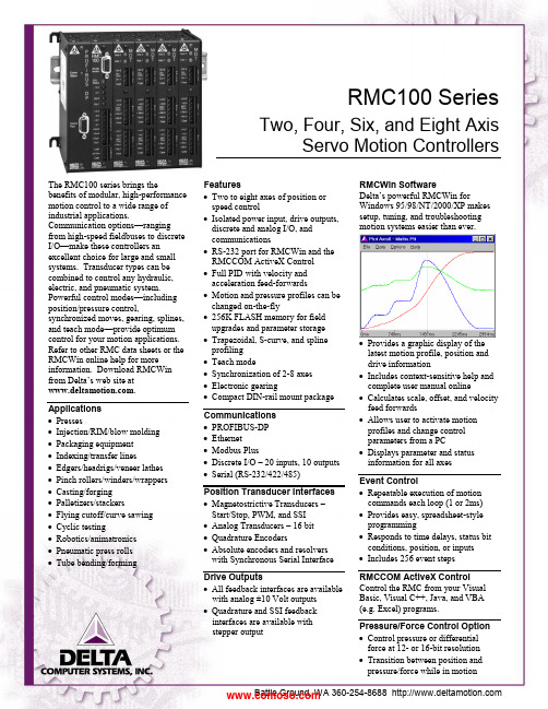
RMC100 SeriesTwo, Four, Six, and Eight AxisServo Motion ControllersThe RMC100 series brings thebenefits of modular, high-performance motion control to a wide range of industrial applications.Communication options —ranging from high-speed fieldbuses to discrete I/O —make these controllers an excellent choice for large and small systems. Transducer types can be combined to control any hydraulic, electric, and pneumatic system. Powerful control modes —including position/pressure control,synchronized moves, gearing, splines, and teach mode —provide optimum control for your motion applications. Refer to other RMC data sheets or the RMCWin online help for more information. Download RMCWin from Delta’s web site at . Applications ∙ Presses∙ Injection/RIM/blow molding ∙ Packaging equipment ∙ Indexing/transfer lines∙ Edgers/headrigs/veneer lathes ∙ Pinch rollers/winders/wrappers ∙ Casting/forging ∙ Palletizers/stackers∙ Flying cutoff/curve sawing ∙ Cyclic testing∙ Robotics/animatronics ∙ Pneumatic press rolls ∙ Tube bending/formingFeatures∙ Two to eight axes of position or speed control∙ Isolated power input, drive outputs, discrete and analog I/O, and communications∙ RS-232 port for RMCWin and the RMCCOM ActiveX Control ∙ Full PID with velocity and acceleration feed-forwards∙ Motion and pressure profiles can be changed on-the-fly∙ 256K FLASH memory for field upgrades and parameter storage ∙ Trapezoidal, S-curve, and spline profiling ∙ Teach mode∙ Synchronization of 2-8 axes ∙ Electronic gearing∙ Compact DIN-rail mount package Communications ∙ PROFIBUS-DP ∙ Ethernet ∙ Modbus Plus∙ Discrete I/O – 20 inputs, 10 outputs ∙ Serial (RS-232/422/485) Position Transducer Interfaces ∙ Magnetostrictive Transducers – Start/Stop, PWM, and SSI ∙ Analog Transducers – 16 bit ∙ Quadrature Encoders∙ Absolute encoders and resolvers with Synchronous Serial Interface Drive Outputs∙ All feedback interfaces are available with analog ±10 Volt outputs ∙ Quadrature and SSI feedback interfaces are available with stepper outputRMCWin SoftwareDelta’s powerful RMCWin fo rWindows 95/98/NT/2000/XP makes setup, tuning, and troubleshootingmotion systems easier than ever.∙ Provides a graphic display of the latest motion profile, position and drive information∙ Includes context-sensitive help and complete user manual online∙ Calculates scale, offset, and velocity feed forwards∙ Allows user to activate motion profiles and change control parameters from a PC∙ Displays parameter and status information for all axesEvent Control∙ Repeatable execution of motion commands each loop (1 or 2ms) ∙ Provides easy, spreadsheet-style programming∙ Responds to time delays, status bit conditions, position, or inputs ∙ Includes 256 event steps RMCCOM ActiveX Control Control the RMC from your Visual Basic, Visual C++, Java, and VBA (e.g. Excel) programs.Pressure/Force Control Option ∙ Control pressure or differential force at 12- or 16-bit resolutionPosition Axis Parameters P ressure/Force Axis Parameters Setup Parameters S etup ParametersConfigurationScaleOffsetExtend LimitRetract LimitProportional GainIntegral GainDifferential Gain Extend Vel. Feed Forward Retract Vel. Feed Forward Extend Accel. Feed Fwd Retract Accel. Feed FwdDead Band EliminatorIn PositionFollowing Error Automatic Stop Enable Controller operating configurationThese fields allow for position unitconversionMaximum position allowedMinimum position allowedProportional gain for PID loopIntegral gain for PID loopDifferential gain for PID loopOpen loop compensation termsproportional to target velocityOpen loop compensation termsproportional to target accelerationValve dead band compensationWindow for in-position indicationAllowable position errorEnable for stop on errorsConfigurationScale AOffset AScale BOffset BProportional GainIntegral GainDifferential GainExtend Feed ForwardRetract Feed ForwardIntegrator PreloadDrive Transfer PercentAt Pressure WindowPressure WindowAutomatic Stop EnableController operating configurationThese fields allow for unitconversion for both pressure anddifferential force transducers.Proportional gain for PID loopIntegral gain for PID loopDifferential gain for PID loopOpen loop compensation termsproportional to pressure changeEnable tuning of bumpless transferfrom position to pressure controlWindow for at-pressure indicationAllowable pressure/force errorEnable for stop on errorsDynamic Control Parameters D ynamic Control ParametersMode AccelerationDecelerationSpeed Command ValueCommand Select from these features:Graph disableS-curve rampsSynchronizationElectronic GearingQuick modeMonitor Pressure modeIntegrator modes(avoid windup and overshoot)Acceleration rate, distance, or timeDeceleration rate, distance, or timeMaximum speed during a moveDestination positionCommand to be executed(refer to online help for complete listof commands)ModePressure Set APressure Set BRamp TimeCommand ValueCommandSelect from these features:Curved and linear rampsAuto-calculated ramp slopeIntegrator modes(avoid windup and overshoot)Pressure control entry thresholdPressure control exit thresholdTime to ramp between pressuresDesired pressureCommand to be executed(refer to online help for complete listof commands)Status Information S tatus InformationCommand Position Target PositionActual Position Transducer CountsStatus WordDriveActual SpeedNull DriveStepLink Value Requested position within limitsCalculated desired position of axisMeasured position based on currentTransducer Counts that have beenScaled and OffsetRaw transducer countsAxis errors and statusDrive output in millivoltsCalculated speedCurrent null drive in millivoltsLast step executedValue at which next step executesCommand Pressure/ForceTarget Pressure/ForceActual Pressure/ForceTransducer Counts ATransducer Counts BActual Force AActual Force BStatus WordDriveRequested pressure/forceCalculated desired pressure/forceCurrently measured pressure/forceRaw value read from analogtransducersValues of each force component in adifferential force applicationAxis errors and statusDrive output in millivoltsFor detailed explanations of these parameters and RMC functionality, refer to RMCWin’s online help. Download RMCWin from Delta’s web site at .RMC100 Series SpecificationsMotion Control Control loop timeMaximum speed 1 or 2 ms depending on module configuration 65,535 user-defined position units per secondRS-232 Port Interface with Delta's RMCWinand RMCCOM ActiveX Control.ConnectorCable Requires a PC with Windows 95/98/Me/NT/2000/XP. DB-9 MaleNull modemRJ-11 LCD Terminal Jack Interface with Delta’s optionalfour-line 20-character LCDdisplay with keypad Allows viewing status information, changing parameters, and issuing commandsDiscrete I/O IsolationLogic PolarityInputsInput voltage thresholdInput current thresholdOutputs 2500 VAC optically isolatedTrue High2; independent (sink or source)6 mA max at 5 V; 10 mA max at 24 V26.4 VDC maximum2.75 VDC typical, 3 VDC Max2.7 mA typical,3.2mA maximum2; independent (sink or source)Solid State Relay, 50 Ω maximum on resistance, 30 V and 100 mA maximum, Tpd max of 1.5 msPower VoltageCurrent – 2 axes (3 slots)4 axes (4 slots)6 axes (5 slots)8 axes (6 slots)DC-DC converter isolation +24 VDC ±20%Typical 290 mA @ 24 VDC, max 375 mA Typical 385 mA @ 24 VDC, max 500 mA Typical 485 mA @ 24 VDC, max 625 mA Typical 585 mA @ 24 VDC, max 750 mA 500 VAC, 700 VDC, input to controllerMechanical MountingDimensions – 2 axes (3 slots)8 axes (6 slots)Weight – 2 axes (3 slots)8 axes (6 slots) Symmetrical DIN 3 or panel-mount4.12 x5.95 x 4.75 in (10.5 x 15.0 x 12.1 cm) (WxHxD) 7.12 x 5.95 x 4.75 in (18.1 x 15.0 x 12.1 cm) (WxHxD)2.0 lb (0.9 kg) max3.0 lb (1.4 kg) maxEnvironment Operating temperatureStorage temperatureAgency compliance +32 to +140︒F (0 to +60︒C) -40 to +185︒F (-40 to +85︒C) CE, UL, CULWiring Information for the RMC100RS-232:Pin Function2 Receive3 Transmit5 CommonPower:Pin Function+24V +24 Volt Input24 Cmn 24 Volt CommonCase Controller Chassis Ground (shield) Discrete I/O:Pin Function+ In 0 + Input 0- In 0 - Input 0+ In 1 + Input 1- In 1 - Input 1+ Out 0 + Output 0- Out 0 - Output 0+ Out 1 + Output 1- Out 1 - Output 1RMC100 Series Part NumbersNot all combinations of modules are possible. See individual data sheets for details on modules and options. This information plus an easy-to-use Price List program are available on our web site at .Accessories Part Number DescriptionLCD420 LCD display and keypad VC2100Voltage-to-current converterSSn-PEn-BGnFamily of Servo System and Position/Pressure SimulatorsCompany ProfileDelta Computer Systems, Inc. manufactures motion controllers, color sensors/sorters, and other industrial controls providing high-performance automation solutions to a wide range of industries.Printed in USA 02/09/10 RMC100 Series.docVC2100 LCD420RMC100-M1-PROFIRMC100-M1-PROFIRMC100 Series CPU Pressure/Force Control Option(0=disabled, 1=enabled)(Multiple options possible)Magnetostrictive Displacement Transducer (MDT) module (Start/Stop and PWM) (designate -M n , n = 1-4 modules; 2 axes per module)Quadrature modules(designate -Q n , n = 1-4 modules; Analog output, 2 axes per module) (designate -QST n , n = 1-4 modules; Stepper output, 2 axes per module) Analog modules(designate -H n , n = 1-4 modules; four 16-bit inputs / 2 axes per module) (designate -G n , n = 1-4 modules; two 16-bit inputs / 2 axes per module) (designate -A n , n = 1-2 modules; four 12-bit inputs only per module) Sensor DI/O module (designate -D1)Synchronous Serial Interface (SSI) modules (MDT, absolute encoder, resolver) (designate -S n , n = 1-4 modules; Analog output, 2 axes per module) (designate -SST n , n = 1-4 modules; Stepper output, 2 axes per module) Communication(designate -PROFI , -DI/O , -MB+, -ENET , -SERIAL ; others in development)。
太阳能电池板双轴自动跟踪伺服控制系统的设计

题目:光伏发电太阳能电池板双轴伺服控制系统研究一、题目说明1、双轴跟踪的基本原理双轴跟踪又可以分为两种方式:极轴式全跟踪和高度----方位角式全跟踪。
极轴式全跟踪原理如图1.1所示,太阳能设备的能量转换部分的一轴指向地球北极,即与地球自转轴相平行,故称为极轴;另一轴与极轴垂直,称为赤纬轴。
工作时太阳能设备的能量转换部分所在平面绕极轴运转,其转速的设定与地球自转角速度大小相同方向相反用以跟踪太阳方位角:反射镜围绕赤纬轴作俯仰转动是为了适应太阳高度角的变化,通常根据季节的变化定期调整养第轴图1.1极轴式跟踪高度角---方位角式太阳跟踪方法又称为地平坐标系双轴跟踪,其原理如图 1.2所示。
太图1.2高度---方位角式全跟踪阳能设备的能量转换部分的方位轴垂直于地平面,另一根轴与方位轴垂直,称为俯仰轴。
工 作时太阳能设备的能量转换部分根据太阳的视日运动绕方位轴转动改变方位角,绕俯仰轴作 俯仰运动改变太阳能设备的能量转换部分的倾斜角,从而使能量转换部分所在平面的主光轴 始终与太阳光线平行。
这种跟踪系统的特点是跟踪精度高,而且太阳能设备的能量转换部分 的重量保持在垂直轴所在的平面内,支承结构的设计比较容易。
2、光伏发电系统光电板自动跟踪系统的原理太阳电池方阵的发电量与阳光入射角有关, 光线与太阳电池方阵平面垂直时发电量最大, 如果改变入射角,发电量将明显下降。
其基本原理与结构为:由 2台电动机和减速机分别构成 方位角转动机构和高度角转动机构,光电传感器与太阳能电池板方阵平面垂直安装。
随着光 线方向的细微改变,传感器失衡,引起系统输出信号产生偏差,达到一定幅度时,方向开关 电路启动,执行机构开始进行纠正,使光电传感器重新达到平衡,即太阳能电池板方阵平面 与光线构成90度角而停止转动,并完成一次调整周期。
如此不断地调整,时刻沿着太阳的运 行轨迹追随太阳,构成一个闭路负反馈系统,实现了跟踪功能。
该系统不需设定基准位置, 跟踪器永远不会迷失方向。
- 1、下载文档前请自行甄别文档内容的完整性,平台不提供额外的编辑、内容补充、找答案等附加服务。
- 2、"仅部分预览"的文档,不可在线预览部分如存在完整性等问题,可反馈申请退款(可完整预览的文档不适用该条件!)。
- 3、如文档侵犯您的权益,请联系客服反馈,我们会尽快为您处理(人工客服工作时间:9:00-18:30)。
图4
图5为无线发射模块
图5
接收模块的安装,元器件朝外
六、LED显示定义,图6
第一个红色LED:快闪表示白天工作,慢闪表示进入黑夜状态,等待第二天继续工作。
第二个绿灯LED:亮表示进入黑夜状态,灭表示白天状态。
第三个绿色LED:亮表示南北电机需要旋转到太阳位置,灭表示南北方向太阳已经到达最佳位置。
3.两个直流电机可双向供电,反向供电电机可反向旋转。
4.电机电流值最好不要超过3A,大电流工作可能会引起MOS管发热,甚至损坏。
5.无线接收模块的带电子元器件朝外侧插入。
6.左上角为电源输入端,右侧为正,反接电源可能造成控制板的损坏。
7.东西方向的旋转电机只有东侧有限位开关,
8.无线控制发射器有效范围大致在10米左右。
本人用的是一个大一些的不锈钢片和两个小一些的钢片焊接到缝隙当中的。注意最好把不锈钢片最后涂成黑色,避免反光。上述步骤需要你自行完成,抱歉我没有给你做出来,实在是不好意思,而且我做完了也不一定符合您的审美观。
传感器的个人焊接过程图片:
后期安装在电池板上的图片:
十三、限位端子,图12
图12
此端子为黑夜后返东的限制开关,为常闭触点,电路板标注SN错误。当黑夜后旋转电机会自动旋转到东侧,到达限位开关后自动断开电机与地的连接,使旋转电机不能再继续往东旋转。当第二天白天后系统往西旋转的时候,限位开关后又合上的。
后三种都没有接入,如果需要的话,联系本人。
图7
八、数码管的显示,图8
数码管显示的是剩余时间,从60分钟到0分钟。如果测试的话每一分钟跟踪一次;如果一小时跟踪的话,则到0跟踪一次;2小时跟踪一次的话,需要两次60到0跟踪一次;同理三小时需要三次60到0的显示状态。
图8
九、RJ45网线接口为传感器的接线口,已经做好,连接上即可,自己做也可。单需要把传感器和板子的接口线顺序反过来。
第四个绿色LED:亮表示东西电机需要旋转到太阳位置,灭表示东西方向太阳已经到达最佳位置。
图6
七、左下角为传感器接入端口,图7
+PV-:表示需要把电池板的正负极接入,来判断黑夜和白天,如果不接入判断为黑夜状态。
+WIN-:表示风速测试接口。
+GM-:表示光敏测试接口。
+X-:表示未知测试接口,用户可自己定义。
KEY5无定义。
图2
三、下边红色拨码开关为跟踪的时间间隔,图3
1:为1小时间隔跟踪一次。
2:为2小时间隔跟踪一次。
3:为3小时间隔跟踪一次。
4:为1分钟间隔跟踪一次(只能作为测试用)
都不拨上的话,默认为1小时间隔跟踪一次。不可以组合拨码。组合默认为1小时。
图3
四、无线控制电机正反转。AB键控制一:复位键。
十一、电机连接,图10
图10
上边的M1端子连接仰俯的电机,下边的M2端子连接旋转的电机。
十二、传感器,图11
图11
上图为传感器的板子,图中有四个光敏电阻,四个光敏电阻之间有两条垂直相交的缝隙,实际应用中,需要你用挡光的材料固定在缝隙当中,目的是要把四个光敏电阻隔开(十字交叉的隔开,每一个象限有一个光敏电阻。当光线从一侧照进来的时候,目的是使光线只能照到其中一个或两个光敏电阻。只有当光线垂直照射到该传感器时,四个光敏电阻被同时照到,此时认为电池板已经达到最佳位置。安装时需要把该传感器板子与电池板平行安装起来)
9.在跟踪的过程当中,如果发现电机反向选择,则需要把电机正负极颠倒一下即可。
10.板子当中有一个三位的红色拨码开关,为烧写程序保护用的。拨到1为保护状态。
11、此控制板为本人实验板,如有差错请谅解。
附件:
1.两个直流电机
2.一根数据线
3.一个接收模块
4.一个发送模块
5.一块控制板
6.一个传感器的板(未完善),需要自行把挡板焊接好。
跟踪原理:在跟踪时刻到的时候分别检测左右和上下两个光敏电阻,判断电机的旋转方向。当到达最佳位置之后,停止旋转。
个人建议:因为此板为控制板,所以支撑电机的力与旋转的力最好成90°。
旋转电机部分垂直向上固定,旋转的力在水平方向,所以旋转电机更省力,也更省电。同理,仰俯的电机也不要硬推电池板,可以再结构上加上对电池板的支撑,用推杆电机推拉电池板,能更省力。
具体连接方法如下:
十四、电机辅助调速,图13
图13
图中有四个蓝色的电位器。其中标注有VR2和VR4的为电机的辅助调速(下边两个为VR2-左下和VR4-右下)。VR1和VR3尽量不要动。
十五、电源输入端子,右正左负。见图14
图14
注意事项:
1.此系统为12V系统,供电电压为9~18V。
2.两个直流电机在任何时刻都要能跟踪到太阳,也就是说在太阳快落山的时候,仰俯方向的电机最好能达到0°~90°,水平面的电机能旋转到-135°~135°。如果两个电机本身所限达不到最佳角度,则两个电机都会等待大约10分钟左右,如果还是旋转角度达不到要求,则系统自动认为电机达不到最佳角度,系统自动返回。等待天黑后返东。
1分钟测试的程序不能长时间用。
本人QQ:344820178
阿里旺旺:ws_taobao
太阳双轴跟踪说明书
此控制板板为太阳能双轴跟踪系统,控制两个直流电机的旋转,使电池板对准太阳。系统为12V系统,所以需要的是两个可以正反转的12V直流电机。实际连接时把仰俯的电机连接到上边,把旋转的电机连接到下边。
一、整体连接图如下:见图1
图1
二、左上角KEY1、KEY2、KEY3、KEY4为手动控制两个电机的正反转,见图2