倍加福NI40-C40-OP6L-Q12
倍加福液位计UB4000-F42-I-V15

零线模式
᱖ذ pause
" 零线模式 " 中指定测量边界 A1 为 0,测量边界 A2 决定输出特性。 按下 A1 键 2 秒钟保存所选的输出模式,完成参数设定并确保接近开关返回标准模 式。再短按 A1 键将开始进行步骤 2 (声锥宽度的选择) 。 步骤 2,超声波声锥宽度的选择 在近距离内,通过步骤 2,超声波声锥的宽度可以根据不同的应用进行调整。 首先显示当前声锥的宽度。 所有可选的声锥宽度可以通过连续短按 A2 键进行选择, 每次按键后红色 LED 的闪烁序列将会发生变化,从而显示不同的声锥宽度。 声锥宽度
Release date: releasedate Issue date: 2007-10-09 134003_CN.xml
红色 LED 的闪烁序列
᱖ذ pause
A2 键
小声锥
中等声锥
pause ᱖ذ
大声锥
pause ᱖ذ
按下 A1 键 2 秒钟保存所选的声锥形状,完成参数设定并确保接近开关返回标准模 式。短按 A1 键将返回步骤 1 (输出功能的设定) 。 如果在进入参数设定模式 5 分钟后没有完成设定,接近开关将不更改任何设置并退 出设定模式。
上升模式
ူইఇ๕ A1 ଭ၍ఇ๕
ఇెଉݛ๕
ப൶
ణՔྷݔ ฉืఇ๕ A1 A2
A2
绿色 LED 的闪烁序列
᱖ذ pause
A2 键
A1 = 0 A2
附件
pause ᱖ذ
下降模式
MH 04-3505 安装附件 MHW 11 安装附件 DA5-IU-2K-V 显示器 V15-G-2M-PVC 电缆连接器 V15-W-2M-PVC 电缆连接器
p+f 安全栅选型样本

1 KFD2-STC3- 10
3 EX1-86C
11
2线制智能变送器
+
AI卡,1-5V
+24VDC 250Ω _ AI卡,4-20mA 驱动2线制变送器
1
KFD2-CR-
8
3
EX1.30200 7
2线制非智能变送器
250Ω
AI卡, 接收有源4-20mA
不保证样本内容毫无差错 样本内容更改时恕不通知 P+F上海 电话021-63542910 P+F北京 电话010-65885145 P+F广州 电话020-38805159
4
11
+
6
10
2线制智能变送器
AI卡,1-5V
KFD2-STC4-Ex1 KFD2-STV4-EX1-1 KFD2-STV4-EX1-2 单通道,2、3 、4线制変送器
控制系统:各款DCS/PLC的AI卡,接收4-20mA 信号(配STC4)或1-5V信号(配STV4-EX1-1)或2-10V 信号(配STV4-EX1-2)。 2、3、4线制HART或Brain智能变送器。 对变送器驱动电压16V。 智能通讯频率0-7.5kHz。 兼容2、3、4线制非智能变送器。
8+
7
11 +
10
2路DCS/ESD的AI卡, 接收1-5V信号(EX1-1) 或2-10V信号(EX1-2)
+
+
1
-
2
-+3
5
+6
2、3线制智能变送器。 4线制智能变送器的有源 4-20mA信号接在5、6端 子。 4线制非智能变送器 有源4-20mA信号接在2、 3端子。
IR公司_大功率MOS管选型

I DContinuous Drain Current(A)70°Micro3Surface Mount PackagesV (BR)DSSDrain-to-Source Breakdown Voltage (V)R DS(on)On-State Resistance ()ΩI D Continuous Drain Current 25°C(A)R ΘMax.Thermal Resistance (°C/W)1FaxonDemand Number Case Outline KeyPartNumberPD Max.PowerDissipation (W)N-ChannelLogic LevelIRLML2402*912570.54200.25 1.20.95230H1IRLML2803912580.54300.251.20.93230P-ChannelLogic LevelIRLML6302*912590.54-200.6-0.62-4.8230H1IRLML5103912600.54-300.6-0.61-4.8230* Indicates low VGS(th), which can operate at VGS = 2.7VMeasured at ambient for Micro3, Micro6, Micro8, SO-8, and SOT-223 package styles. All others measured at case.1Micro3SO-8D-PakD -PakSOT-227Micro6SOT-223Micro82 Illustrations not to scaleI DContinuous Drain Current(A)70°Micro6Surface Mount PackagesV (BR)DSSDrain-to-Source Breakdown Voltage (V)R DS(on)On-State Resistance ()ΩI D Continuous Drain Current 25°C(A)R ΘMax.Thermal Resistance (°C/W)1FaxonDemand Number Case Outline KeyPartNumberPD Max.PowerDissipation (W)N-ChannelLogic LevelIRLMS1902915401.7200.10 3.2 2.675H2IRLMS1503915081.7300.103.22.675P-ChannelLogic LevelIRLMS6702*914141.7-200.20-2.3-1.975H2IRLMS5703914131.7-300.20-2.3-1.975* Indicates low VGS(th), which can operate at VGS = 2.7VMeasured at ambient for Micro3, Micro6, Micro8, SO-8, and SOT-223 package styles. All others measured at case.1Micro3SO-8D-PakD -PakSOT-227Micro6SOT-223Micro82 Illustrations not to scaleI DContinuous Drain Current(A)70°Micro8Surface Mount PackagesV (BR)DSSDrain-to-Source Breakdown Voltage (V)R DS(on)On-State Resistance ()ΩI D Continuous Drain Current 25°C(A)R ΘMax.Thermal Resistance (°C/W)1FaxonDemand Number Case Outline KeyPart NumberP D Max.PowerDissipation (W)N-Channel Logic LevelIRF7601* 912611.820 0.035 5.7 4.6 70 H3IRF7603 912621.830 0.035 5.6 4.5 70Dual N-Channel Logic LevelIRF7501* 912651.220 0.135 2.4 1.9 100 H3IRF7503 912661.2530 0.135 2.4 1.9 100P-Channel Logic LevelIRF7604* 912631.8-20 0.09 -3.6 -2.9 70 H3IRF7606 912641.8-30 0.09 -3.6 -2.9 70Dual P-Channel Logic LevelIRF7504* 912671.25-20 0.27 -1.7 -1.4 100 H3IRF7506 912681.25-30 0.27 -1.7 -1.4 100Dual N- and P-Channel Logic LevelIRF7507* 912691.2520 0.1352.4 1.9 100 H3-20 0.27 -1.7 -1.4IRF7509 912701.2530 0.135 2.4 1.9 100-30 0.27 -1.7 -1.4* Indicates low VGS(th), which can operate at VGS = 2.7VMeasured at ambient for Micro3, Micro6, Micro8, SO-8, and SOT-223 package styles. All others measured at case.1Micro3SO-8D-Pak D -PakSOT-227Micro6SOT-223Micro8 2 Illustrations not to scaleI DContinuous Drain Current(A)70°SO-8Surface Mount PackagesV (BR)DSSDrain-to-Source Breakdown Voltage (V)R DS(on)On-State Resistance ()ΩI D Continuous Drain Current 25°C(A)R ΘMax.Thermal Resistance (°C/W)1FaxonDemand Number Case Outline KeyPart Number P D Max.PowerDissipation (W)N-ChannelIRF7413913302.5300.011139.250H4IRF7413A 916132.5300.0135128.450IRF9410915622.5300.0375.850Dual N-ChannelIRF7311914352.0200.029 6.6 5.362.5H4IRF7313914802.0300.029 6.5 5.262.5IRF7333917002.0300.10 3.5 2.862.5917002.0300.050 4.9 3.962.5IRF9956915592.0300.103.52.862.5Dual P-ChannelIRF7314914352.0-200.058-5.3-4.362.5H4IRF7316915052.0-300.058-4.9-3.962.5IRF9953915602.0-300.25-2.3-1.862.5* Indicates low VGS(th), which can operate at VGS = 2.7VMeasured at ambient for Micro3, Micro6, Micro8, SO-8, and SOT-223 package styles. All others measured at case.1Micro3SO-8D-PakD -PakSOT-227Micro6SOT-223Micro82 Illustrations not to scaleI DContinuous Drain Current(A)70°SO-8Surface Mount PackagesV (BR)DSSDrain-to-Source Breakdown Voltage (V)R DS(on)On-State Resistance ()ΩI D Continuous Drain Current 25°C(A)RΘMax.ThermalResistance(°C/W)1FaxonDemand Number Case Outline KeyPart NumberP D Max.PowerDissipation (W)Dual N- and P-ChannelIRF7317 915682.020 0.029 6.6 5.3 62.5 H42.0-20 0.058 -5.3 -4.3 62.5IRF9952 915622.030 0.103.5 2.8 62.5915622.0-30 0.25 -2.3 -1.8 62.5IRF7319 916062.030 0.029 6.5 5.2 62.52.0-30 0.058 -4.9 -3.9 62.5* Indicates low VGS(th), which can operate at VGS = 2.7VMeasured at ambient for Micro3, Micro6, Micro8, SO-8, and SOT-223 package styles. All others measured at case.1Micro3SO-8D-Pak D -PakSOT-227Micro6SOT-223Micro8 2 Illustrations not to scaleI DContinuous Drain Current(A)70°SO-8Surface Mount PackagesV (BR)DSSDrain-to-Source Breakdown Voltage (V)R DS(on)On-State Resistance ()ΩI D Continuous Drain Current 25°C(A)R ΘMax.Thermal Resistance (°C/W)1FaxonDemand Number Case Outline KeyPart Number P D Max.PowerDissipation (W)N-ChannelLogic LevelIRF7401912442.5200.0228.77.050H4IRF7201911002.5300.0307.0 5.650IRF7403912452.5300.0228.55.450Dual N-ChannelLogic LevelIRF7101908712.0200.10 3.5 2.362.5H4IRF7301912382.0200.050 5.2 4.162.5IRF7303912392.0300.050 4.9 3.962.5IRF7103910952.0500.1303.02.362.5P-ChannelLogic LevelIRF7204911032.5-200.060-5.3-4.250H4IRF7404912462.5-200.040-6.7-5.450IRF7205911042.5-300.070-4.6-3.750IRF7406912472.5-300.045-5.8-3.750IRF7416913562.5-300.02-10-7.150* Indicates low VGS(th), which can operate at VGS = 2.7VMeasured at ambient for Micro3, Micro6, Micro8, SO-8, and SOT-223 package styles. All others measured at case.1Micro3SO-8D-PakD -PakSOT-227Micro6SOT-223Micro82 Illustrations not to scaleI DContinuous Drain Current(A)70°SO-8Surface Mount PackagesV (BR)DSSDrain-to-Source Breakdown Voltage (V)R DS(on)On-State Resistance ()ΩI D Continuous Drain Current 25°C(A)R ΘMax.Thermal Resistance (°C/W)1FaxonDemand Number Case Outline KeyPart Number P D Max.PowerDissipation (W)Dual P-ChannelLogic LevelIRF7104910962.0-200.250-2.3-1.862.5H4IRF7304912402.0-200.090-4.3-3.462.5IRF7306912412.0-300.10-3.6-2.962.5Dual N- and P-Channe Logic LevelIRF7307912421.4200.050 4.3 3.490H4-200.090-3.6-2.9IRF7105910972.0250.1093.5 2.862.52-250.25-2.3-1.862IRF7309912432.0300.050 4.9 3.962.5-300.10-3.6-2.9* Indicates low VGS(th), which can operate at VGS = 2.7VMeasured at ambient for Micro3, Micro6, Micro8, SO-8, and SOT-223 package styles. All others measured at case.1Micro3SO-8D-PakD -PakSOT-227Micro6SOT-223Micro82 Illustrations not to scaleI DContinuous Drain Current(A)70°SOT-223Surface Mount PackagesV (BR)DSSDrain-to-Source Breakdown Voltage (V)R DS(on)On-State Resistance ()ΩI D Continuous Drain Current 25°C(A)R ΘMax.Thermal Resistance (°C/W)1FaxonDemand Number Case Outline KeyPart Number P D Max.PowerDissipation (W)N-ChannelIRFL4105913812.1550.045 3.7 3.060H6IRFL110908612.01000.54 1.50.9660IRFL4310913682.11000.20 1.6 1.360IRFL21090868 2.02001.50.960.660IRFL214908622.02502.00.790.560P-ChannelIRFL9110908642.0-1001.2-1.1-0.6960H6N-ChannelLogic LevelIRLL3303913792.1300.031 4.6 3.760H6IRLL014N 914992.1550.14 2.0 1.660IRLL2705913802.1550.043.83.060* Indicates low VGS(th), which can operate at VGS = 2.7VMeasured at ambient for Micro3, Micro6, Micro8, SO-8, and SOT-223 package styles. All others measured at case.1Micro3SO-8D-PakD -PakSOT-227Micro6SOT-223Micro82 Illustrations not to scaleI DContinuous Drain Current(A)100°D-PakSurface Mount PackagesV (BR)DSSDrain-to-Source Breakdown Voltage (V)R DS(on)On-State Resistance ()ΩI D Continuous Drain Current 25°C(A)R ΘMax.Thermal Resistance (°C/W)1FaxonDemand Number Case Outline KeyPart Number P D Max.PowerDissipation (W)N-ChannelIRFR33039164257300.0313321 2.2H7IRFR024N9133638550.0751610 3.3IRFR41059130248550.0452516 2.7IRFR12059131869550.0273723 1.8IRFR11090524251000.54 4.3 2.75IRFR120N 91365391000.219.1 5.8 3.2IRFR391091364521000.11159.5 2.4IRFR2109052625200 1.5 2.6 1.75IRFR22090525422000.8 4.833IRFR21490703252502 2.2 1.45IRFR2249060042250 1.1 3.8 2.43IRFR3109059725400 3.6 1.7 1.15IRFR3209059842400 1.8 3.123IRFR42090599425003 2.4 1.53IRFRC2090637426004.421.33* Indicates low VGS(th), which can operate at VGS = 2.7VMeasured at ambient for Micro3, Micro6, Micro8, SO-8, and SOT-223 package styles. All others measured at case.1Micro3SO-8D-PakD -PakSOT-227Micro6SOT-223Micro82 Illustrations not to scaleI DContinuous Drain Current(A)100°D-PakSurface Mount PackagesV (BR)DSSDrain-to-Source Breakdown Voltage (V)R DS(on)On-State Resistance ()ΩI D Continuous Drain Current 25°C(A)R ΘMax.Thermal Resistance (°C/W)1FaxonDemand Number Case Outline KeyPart Number P D Max.PowerDissipation (W)P-ChannelIRFR55059161057-550.11-18-11 2.2H7IRFR53059140289-550.065-28-18 1.4IRFR90149065425-600.5-5.1-3.25IRFR90249065542-600.28-8.8-5.63IRFR91109051925-100 1.2-3.1-25IRFR91209052042-1000.6-5.6-3.63IRFR9120N 9150739-1000.48-6.5-4.1 3.2IRFR92109052125-2003-1.9-1.25IRFR92209052242-200 1.5-3.6-2.33IRFR92149165850-250 3.0-2.7-1.7 2.5IRFR93109166350-4007.0-1.8-1.12.5* Indicates low VGS(th), which can operate at VGS = 2.7VMeasured at ambient for Micro3, Micro6, Micro8, SO-8, and SOT-223 package styles. All others measured at case.1Micro3SO-8D-PakD -PakSOT-227Micro6SOT-223Micro82 Illustrations not to scaleI DContinuous Drain Current(A)100°D-PakSurface Mount PackagesV (BR)DSSDrain-to-Source Breakdown Voltage (V)R DS(on)On-State Resistance ()ΩI D Continuous Drain Current 25°C(A)R ΘMax.Thermal Resistance (°C/W)1FaxonDemand Number Case Outline KeyPart Number P D Max.PowerDissipation (W)N-ChannelLogic LevelIRLR27039133538300.0452214 3.3H7IRLR33039131657300.0313321 2.2IRLR31039133369300.0194629 1.8IRLR024N 9136338550.0651711 3.3IRLR27059131746550.042415 2.7IRLR29059133469550.0273623 1.8IRLR120N 91541391000.18511 6.9 3.2IRLR341091607521000.10159.52.4* Indicates low VGS(th), which can operate at VGS = 2.7VMeasured at ambient for Micro3, Micro6, Micro8, SO-8, and SOT-223 package styles. All others measured at case.1Micro3SO-8D-PakD -PakSOT-227Micro6SOT-223Micro82 Illustrations not to scaleI DContinuous Drain Current(A)100°D 2PakSurface Mount PackagesV (BR)DSSDrain-to-Source Breakdown Voltage (V)R DS(on)On-State Resistance ()ΩI D Continuous Drain Current 25°C(A)R ΘMax.Thermal Resistance (°C/W)1FaxonDemand Number Case Outline KeyPart NumberP D Max.PowerDissipation (W)N-ChannelIRFZ24NS 913554555 0.07 17 12 3.3 H10IRFZ34NS 913116855 0.04 29 20 2.2IRFZ44NS 9131511055 0.022 49 35 1.4IRFZ46NS 9130512055 0.020 53 37 1.3IRFZ48NS 9140814055 0.016 64 45 1.1IRF1010NS 913723.855 0.011 84 60 40IRF3205S 9130420055 0.008 110 80 0.75IRFZ44ES 9171411060 0.023 48 34 1.4IRF1010ES 9172017060 0.012 83 59 0.90IRF2807S 9151815075 0.013 71 50 1.0IRF520NS 9134047100 0.2 9.5 6.7 3.2IRF530NS 9135263100 0.11 15 11 2.4IRF540NS 91342110100 0.052 27 19 1.6IRF1310NS 91514120100 0.036 36 25 1.3IRF3710S 91310150100 0.028 46 33 1.0IRF3315S 9161794150 0.082 21 15 1.6IRF3415S 91509150150 0.042 37 26 1.0IRFBC20S 9.101450600 4.4 2.2 1.4 2.5IRFBC30S 9101574600 2.2 3.6 2.3 1.7IRFBC40S 91016130600 1.2 6.2 3.9 1.0* Indicates low VGS(th), which can operate at VGS = 2.7VMeasured at ambient for Micro3, Micro6, Micro8, SO-8, and SOT-223 package styles. All others measured at case.1Micro3SO-8D-Pak D -PakSOT-227Micro6SOT-223Micro8 2 Illustrations not to scaleI DContinuous Drain Current(A)100°D 2PakSurface Mount PackagesV (BR)DSSDrain-to-Source Breakdown Voltage (V)R DS(on)On-State Resistance ()ΩI D Continuous Drain Current 25°C(A)R ΘMax.Thermal Resistance (°C/W)1FaxonDemandNumberCase Outline KeyPart NumberP D Max.PowerDissipation (W)IRFBF20S 9166554900 8.0 1.7 1.1 2.3 H10P-ChannelIRF5305S 91386110-55 0.06 -31 -22 1.4 H10IRF4905S 914783.8-55 0.02 -74 -52 40IRF9520NS 9152247-100 0.48 -6.7 -4.8 3.2IRF9530NS 9152375-100 0.20 -14 -9.9 2.0IRF9540NS 9148394-100 0.117 -19 -13 1.6IRF5210S 91405150-100 0.06 -35 -25 1.0* Indicates low VGS(th), which can operate at VGS = 2.7VMeasured at ambient for Micro3, Micro6, Micro8, SO-8, and SOT-223 package styles. All others measured at case.1Micro3SO-8D-Pak D -PakSOT-227Micro6SOT-223Micro8 2 Illustrations not to scaleI DContinuous Drain Current(A)100°D 2PakSurface Mount PackagesV (BR)DSSDrain-to-Source Breakdown Voltage (V)R DS(on)On-State Resistance ()ΩI D Continuous Drain Current 25°C(A)R ΘMax.Thermal Resistance (°C/W)1FaxonDemand Number Case Outline KeyPart NumberP D Max.PowerDissipation (W)N-Channel Logic LevelIRL3302S 916925720 0.020 39 25 2.2 H10IRL3202S916756920 0.016 48 30 1.8IRL3102S 916918920 0.013 61 39 1.4IRL3402S 9169311020 0.01 85 54 1.1IRL3502S 9167614020 0.007 110 67 0.89IRL2703S 913604530 0.04 24 17 3.3IRL3303S 913236830 0.026 38 27 2.2IRL3103S 9133811030 0.014 64 45 1.4IRL2203NS 9136717030 0.007 116 82 0.90IRL3803S 9131920030 0.006 140 98 0.75IRLZ24NS 913584555 0.06 18 13 3.3IRLZ34NS 913086855 0.035 30 21 2.2IRLZ44NS 9134711055 0.022 47 33 1.4IRL3705NS 9150217055 0.01 89 63 0.90IRL2505S 9132620055 0.008 104 74 0.75IRLZ44S 9090615060 0.028 50 36 1.0IRL530NS 9134963100 0.1 15 11 2.4IRL2910S 91376150100 0.026 48 34 1.0* Indicates low VGS(th), which can operate at VGS = 2.7VMeasured at ambient for Micro3, Micro6, Micro8, SO-8, and SOT-223 package styles. All others measured at case.1Micro3SO-8D-Pak D -PakSOT-227Micro6SOT-223Micro8 2 Illustrations not to scaleI DContinuous Drain Current(A)100°SOT-227Surface Mount PackagesV (BR)DSSDrain-to-Source Breakdown Voltage (V)R DS(on)On-State Resistance ()ΩI D Continuous DrainCurrent 25°C(A)RΘMax.Thermal Resistance (°C/W)1FaxonDemand Number Case Outline KeyPart Number P D Max.PowerDissipation (W)N-ChannelFully Isolated Low ChargeFA38SA50LC 916155005000.1338240.25H21FA57SA50LC916506255000.0857360.20* Indicates low VGS(th), which can operate at VGS = 2.7VMeasured at ambient for Micro3, Micro6, Micro8, SO-8, and SOT-223 package styles. All others measured at case.1Micro3SO-8D-PakD -PakSOT-227Micro6SOT-223Micro82 Illustrations not to scaleI DContinuous Drain Current(A)100°I-PakThrough-Hole PackagesV (BR)DSSDrain-to-Source Breakdown Voltage (V)R DS(on)On-State Resistance ()ΩI D Continuous Drain Current 25°C(A)R ΘMax.Thermal Resistance (°C/W)1FaxonDemand Number Case Outline KeyPart Number P D Max.PowerDissipation (W)N-ChannelIRFU33039164257300.0313321 2.2H8IRFU024N 9133638550.0751610 3.3IRFU41059130248550.0452519 2.7IRFU12059131869550.0273723 1.8IRFU11090524251000.54 4.3 2.7 5.0IRFU120N 91365391000.219.1 5.8 3.2IRFU391091364521000.11159.5 2.4IRFU2109052625200 1.5 2.6 1.7 5.0IRFU22090525422000.80 4.8 3.0 3.0IRFU2149070325250 2.0 2.2 1.4 5.0IRFU2249060042250 1.1 3.8 2.4 3.0IRFU3109059725400 3.6 1.7 1.1 5.0IRFU3209059842400 1.8 3.1 2.0 3.0IRFU4209059942500 3.0 2.4 1.5 3.0IRFUC2090637426004.42.01.33.0I-PakTO-220 FullPakTO-262TO-247HEXDIPTO-220AB Illustrations not to scale** Not ratedI DContinuous Drain Current(A)100°I-PakThrough-Hole PackagesV (BR)DSSDrain-to-Source Breakdown Voltage (V)R DS(on)On-State Resistance ()ΩI D Continuous Drain Current 25°C(A)R ΘMax.Thermal Resistance (°C/W)1FaxonDemand Number Case Outline KeyPart Number P D Max.PowerDissipation (W)P-ChannelIRFU55059161057-550.11-18-11 2.2H8IRFU53059140289-550.065-28-18 1.4IRFU90149065425-600.50-5.1-3.2 5.0IRFU90249065542-600.28-8.8-5.6 3.0IRFU91109051925-100 1.2-3.1-2.0 5.0IRFU91209052042-1000.60-5.6-3.6 3.0IRFU9120N 9150739-1000.48-6.5-4.1 3.2IRFU92109052125-200 3.0-1.9-1.2 5.0IRFU92209052242-200 1.5-3.6-2.3 3.0IRFU92149165850-2503.0-2.7-1.7 2.5IRFU93109166350-4007.0-1.8-1.12.5N-ChannelLogic LevelIRLU27039133538300.0452214 3.3H8IRLU33039131657300.0313321 2.2IRLU31039133369300.0194629 1.8IRLU024N 9136338550.0651711 3.3IRLU27059131746550.04241715IRLU29059133469550.0273623 1.8IRLU120N 91541391000.18511 6.9 3.2IRLU341091607521000.10159.52.4I-PakTO-220 FullPakTO-262TO-247HEXDIPTO-220AB Illustrations not to scale** Not ratedI DContinuous Drain Current(A)100°HEXDIPThrough-Hole PackagesV (BR)DSSDrain-to-Source Breakdown Voltage (V)R DS(on)On-State Resistance ()ΩI D Continuous Drain Current 25°C(A)R ΘMax.Thermal Resistance (°C/W)1FaxonDemand Number Case Outline KeyPart Number P D Max.PowerDissipation (W)N-ChannelIRFD014907001.3600.2 1.7 1.2120H9IRFD024906991.3600.1 2.5 1.8120IRFD110903281.31000.54 1.00.71120IRFD120903851.31000.27 1.30.94120IRFD210903861.3200 1.50.60.38120IRFD220904171.32000.80.80.50120IRFD214912711.3250 2.00.570.32120IRFD224912721.3250 1.10.760.43120IRFD310912251.3400 3.60.420.23120IRFD320912261.3400 1.80.600.33120IRFD420912271.3500 3.00.460.26120IRFDC20912281.36004.40.320.21120I-PakTO-220 FullPakTO-262TO-247HEXDIPTO-220AB Illustrations not to scale** Not ratedI D Continuous Drain Current (A)100°TO-220Qg TotalGate Charge(nC)Through-Hole PackagesV (BR)DSSDrain-to-Source Breakdown Voltage (V)R DS(on)On-State Resistance ()ΩI D Continuous Drain Current 25°C (A)R ΘMax.Thermal Resistance(°C/W)1Faxon Demand Number Case OutlineKeyPart Number P D Max.Power Dissipation (W)N-ChannelLow ChargeIRF737LC91314743000.75 6.1** 1.7 3.9H11IRF740LC 910681254000.5510** 1.039IRF840LC 910691255000.858.0** 1.039IRFBC40LC910701256001.26.2**1.039I-PakTO-220 FullPakTO-262TO-247HEXDIPTO-220AB Illustrations not to scale** Not ratedI DContinuous Drain Current(A)100°TO-220ABThrough-Hole PackagesV (BR)DSSDrain-to-Source Breakdown Voltage (V)R DS(on)On-State Resistance ()ΩI D Continuous Drain Current 25°C(A)R ΘMax.Thermal Resistance (°C/W)1FaxonDemand Number Case Outline KeyPart Number P D Max.PowerDissipation (W)N-ChannelIRFZ24N 9135445550.071712 3.3H12IRFZ34N9127656550.042618 2.7IRFZ44N 9130383550.0244129 1.8IRFZ46N 9127788550.024633 1.7IRFZ48N 9140694550.0165337 1.6IRF1010N 91278130550.0127251 1.2IRF320591279150550.0089869 1.0IRFZ34E 9167268600.0422820 2.2IRFZ44E 91671110600.0234834 1.4IRF1010E 91670170600.01281570.90IRF280791517150750.0137150 1.0IRF520N 91339471000.209.5 6.79.5IRF530N 91351601000.111511 2.4IRF540N 91341941000.0522719 1.6IRF1310N 916111201000.0363625 1.3IRF3710913091501000.0284633 1.0IRF331591623941500.0822115 1.6IRF3415914771501500.0423726 1.0IRFBC209062350600 4.4 2.2 1.4 2.5IRFBC309048274600 2.2 3.6 2.3 1.7IRFBC4090506125600 1.2 6.2 3.9 1.0IRFBE2090610548006.51.81.22.3I-PakTO-220 FullPakTO-262TO-247HEXDIPTO-220AB Illustrations not to scale** Not ratedI DContinuous Drain Current(A)100°TO-220ABThrough-Hole PackagesV (BR)DSSDrain-to-Source Breakdown Voltage (V)R DS(on)On-State Resistance ()ΩI D Continuous Drain Current 25°C(A)R ΘMax.Thermal Resistance (°C/W)1FaxonDemand Number Case Outline KeyPart Number P D Max.PowerDissipation (W)IRFBE3090613125800 3.0 4.1 2.6 2.0H12IRFBF3090616125900 3.7 3.6 2.3 1.0IRFBG209060454100011 1.40.86 2.3IRFBG309062012510005.03.12.01.0P-ChannelIRF9Z24N 9148445-550.175-12-8.53.3H12IRF9Z34N 9148556-550.10-17-12 2.7IRF530591385110-550.06-31-22 1.4IRF490591280150-550.02-64-45 1.0IRF9530N 9148275-1000.20-13-9.2 2.0IRF9540N 9143794-1000.117-19-13 1.6IRF521091434150-1000.06-35-25 1.0IRF62159147983-1500.29-11-7.81.8I-PakTO-220 FullPakTO-262TO-247HEXDIPTO-220AB Illustrations not to scale** Not ratedI DContinuous Drain Current(A)100°TO-220ABThrough-Hole PackagesV (BR)DSSDrain-to-Source Breakdown Voltage (V)R DS(on)On-State Resistance ()ΩI D Continuous Drain Current 25°C(A)R ΘMax.Thermal Resistance (°C/W)1FaxonDemand Number Case Outline KeyPart NumberP D Max.PowerDissipation (W)N-Channel Logic LevelIRL3302 916965720 0.020 39 25 2.2 H12IRL3202 916956920 0.016 48 30 1.8IRL3102 916948920 0.013 61 39 1.4IRL3402 9169711020 0.01 85 54 1.1IRL3502 9169814020 0.007 110 67 0.89IRL2703 913594530 0.04 24 17 3.3IRL3303 913225630 0.026 34 24 2.7IRL3103 913378330 0.014 56 40 1.8IRL2203N 9136613030 0.007 100 71 1.230 0.007 61 43 3.2IRL3803 9130115030 0.006 120 83 1.0IRLZ24N 913574555 0.06 18 13 3.3IRLZ34N 913075655 0.035 27 19 2.7IRLZ44N 913468355 0.022 41 29 1.8IRL3705N 9137013055 0.01 77 54 1.2IRL2505 9132520055 0.008 104 74 0.75IRL520N 9149447100 0.18 10 7.1 3.2IRL530N 9134863100 0.10 15 11 2.4IRL540N 9149594100 0.044 30 21 1.6IRL2910 91375150100 0.026 48 34 1.0I-PakTO-220 FullPakTO-262TO-247HEXDIPTO-220AB Illustrations not to scale** Not ratedI D Continuous Drain Current (A)100°TO-220 FullPak (Fully Isolated)Qg TotalGate Charge(nC)Through-Hole PackagesV (BR)DSSDrain-to-Source Breakdown Voltage (V)R DS(on)On-State Resistance ()ΩI D Continuous DrainCurrent 25°C(A)R ΘMax.Thermal Resistance (°C/W)1Fax on Demand Number Case OutlineKeyPart Number P D Max.Power Dissipation (W)N-ChannelLow ChargeIRFI740GLC91209404000.55 6.0** 3.139H13IRFI840GLC 91208405000.85 4.8** 3.139IRFIBC40GLC91211406001.24.0**3.139I-PakTO-220 FullPakTO-262TO-247HEXDIPTO-220AB Illustrations not to scale** Not ratedI DContinuous Drain Current(A)100°TO-220 FullPak (Fully Isolated)Through-Hole PackagesV (BR)DSSDrain-to-Source Breakdown Voltage (V)R DS(on)On-State Resistance ()ΩI D Continuous Drain Current 25°C(A)R ΘMax.Thermal Resistance (°C/W)1FaxonDemand Number Case Outline KeyPart Number P D Max.PowerDissipation (W)N-ChannelIRFIZ24N 9150126550.07139.2 5.8H14IRFIZ34N9148931550.041913 4.8IRFIZ44N 9140338550.02428200.024IRFIZ46N 9130640550.023122 3.8IRFIZ48N 9140742550.0163625 3.6IRFI1010N 9137347550.0124431 3.2IRFI32059137448550.0085640 3.1IRFIZ24E 9167329600.071149.6 5.2IRFIZ34E 9167437600.0422115 4.1IRFI510G 90829271000.54 4.5 3.2 5.5IRFI520N 91362271000.207.2 5.1 5.5IRFI530N 91353331000.11117.8 4.5IRFI540N 91361421000.0521813 3.6IRFI1310N 91611451000.0362216 3.3IRFI371091387481000.0252820 3.1IRFI620G 90832302000.8 4.1 2.6 4.1IRFI630G 90652322000.4 5.9 3.7 3.6IRFI640G 90649402000.189.8 6.2 3.1IRFI614G 9083123250 2.0 2.1 1.3 5.5IRFI624G 9083330250 1.1 3.4 2.2 4.1IRFI634G 90738322500.45 5.6 3.5 3.6IRFI644G 90739402500.287.953.1I-PakTO-220 FullPakTO-262TO-247HEXDIPTO-220AB Illustrations not to scale** Not ratedI DContinuous Drain Current(A)100°TO-220 FullPak (Fully Isolated)Through-Hole PackagesV (BR)DSSDrain-to-Source Breakdown Voltage (V)R DS(on)On-State Resistance ()ΩI D Continuous Drain Current 25°C(A)R ΘMax.Thermal Resistance (°C/W)1FaxonDemand Number Case Outline KeyPart Number P D Max.PowerDissipation (W)IRFI720G 9083430400 1.8 2.6 1.7 4.1H14IRFI730G 9065032400 1.0 3.7 2.3 3.6IRFI740G 90651404000.55 5.4 3.4 3.1IRFI734G 9100135450 1.2 3.4 2.1 3.6IRFI744G 91002404500.63 4.9 3.1 3.1IRFI820G 9064130500 3.0 2.1 1.3 4.1IRFI830G 9064632500 1.5 3.12 3.6IRFI840G 90642405000.85 4.6 2.9 3.1IRFIBC20G 90850306004.41.71.1 4.1IRFIBC30G 90851356002.2 2.5 1.63.6IRFIBC40G 9085240600 1.2 3.5 2.2 3.1IRFIBE20G 9085330800 6.5 1.4.86 4.1IRFIBE30G 9085435800 3.0 2.1 1.4 3.6IRFIBF20G 90855309008.0 1.2.79 4.1IRFIBF30G90856359003.71.91.23.6P-ChannelIRFI9Z24N 9152929-550.175-9.5-6.7 5.2H14IRFI9Z34N 9153037-550.10-14-10 4.1IRFI49059152663-550.02-41-29 2.4IRFI9540G 9083742-1000.117-13-9.2 3.6IRFI9540N 9148742-1000.117-13-9.2 3.6IRFI52109140448-1000.06-20-14 3.1IRFI9634G 9148835-2501.0-4.1-2.63.6I-PakTO-220 FullPakTO-262TO-247HEXDIPTO-220AB Illustrations not to scale** Not ratedI DContinuous Drain Current(A)100°TO-220 FullPak (Fully Isolated)Through-Hole PackagesV (BR)DSSDrain-to-Source Breakdown Voltage (V)R DS(on)On-State Resistance ()ΩI D Continuous Drain Current 25°C(A)R ΘMax.Thermal Resistance (°C/W)1FaxonDemand Number Case Outline KeyPart Number P D Max.PowerDissipation (W)N-ChannelLogic LevelIRLI2203N 9137847300.0076143 3.2H14IRLI38039132048300.0066747 3.1IRLIZ24N 9134426550.06149.9 5.8IRLIZ34N 9132931550.0352014 4.8IRLIZ44N 9149838550.0222820 4.0IRLI3705N 9136947550.014733 3.2IRLI25059132763550.00858412.4IRLI520N 91496271000.187.7 5.4 5.5IRLI530N 91350331000.10117.8 4.5IRLI540N 91497421000.04420143.6IRLI291091384481000.02627193.1P-ChannelLogic LevelIRFI9520G 9083537-1000.6-5.2-3.6 4.1H14IRFI9530G 9083638-1000.03-7.7-5.4 3.6IRFI9620G 9087430-200 1.5-3.0-1.9 4.1IRFI9630G 9083840-2000.8-4.3-2.7 3.6IRFI9640G9083940-2000.5-6.1-3.93.1I-PakTO-220 FullPakTO-262TO-247HEXDIPTO-220AB Illustrations not to scale** Not ratedI D Continuous Drain Current (A)100°TO-247Qg TotalGate Charge(nC)Through-Hole PackagesV (BR)DSSDrain-to-Source Breakdown Voltage (V)R DS(on)On-State Resistance ()ΩI D Continuous Drain Current 25°C (A)R ΘMax.Thermal Resistance (°C/W)1Fax on Demand Number Case OutlineKeyPart Number P D Max.Power Dissipation (W)1N-ChannelLow ChargeIRFP350LC912291904000.3018**0.6570H16IRFP360LC 912302804000.2023**0.4598IRFP450LC 912311905000.4016**0.6570IRFP460LC 912322805000.2720**0.4598IRFPC50LC 912331906000.6013**0.6570IRFPC60LC912342806000.4016**0.4598I-PakTO-220 FullPakTO-262TO-247HEXDIPTO-220AB Illustrations not to scale** Not rated。
备品备件(仪电部20101001)
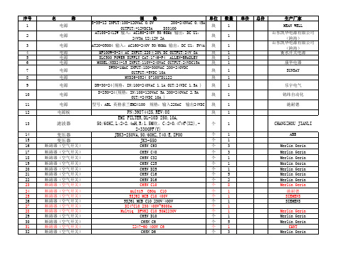
规 格 C65N C4 C65N D4 Z247-60 400V C2 C65N C2 C65N规格D2 C65N D2 C65N 400V50Hz C1 Z247-60 400V C1 GV2M308/2.5-4A规格 GV2ME07/1.6-2.5A GV2ME10/4-6.3A GV2ME16/9-214A SREAW RMC1-63 C6
PN:39874425,REV:08 EMI FILTER,DL-10D 250,10A, 50/60HZ,L:2*2.4mH,R:1.5M欧,C:2*0.47µF(X2),2*3300PF(Y) JBK3-250VA,50/60HZ,T40/E,IPOO JK3-550
C65N C63 C65N C40 C65N C32 C65N C25 C65N D25 C65N C16 C65N D16 C65N C10 multi9 C60a C10 5SJ62 MCB C10 400V 5SJ61 MCB C10 230V/400V DZ47C10 230/400V~6000A Multiq DPNK2 C10 50HZ230V C65N D10 C65N C6 Z247-60 400V C6 C65N D6
乐宇电气 铭纬自动化 施耐德
滤波器 变压器 变压器
断路器(空气开关) 断路器(空气开关) 断路器(空气开关) 断路器(空气开关) 断路器(空气开关) 断路器(空气开关) 断路器(空气开关) 断路器(空气开关) 断路器(空气开关) 断路器(空气开关) 断路器(空气开关) 断路器(空气开关) 断路器(空气开关) 断路器(空气开关) 断路器(空气开关) 断路器(空气开关) 断路器(空气开关)
单价
总价
生产厂家 Merlin Gerin Merlin Gerin CHNT Merlin Gerin Merlin Gerin Merlin Gerin Merlin Gerin CHNT 施奈德 Telemecanique Telemecanique Telemecanique 上海人民电器厂
ERDN40-SPEC 2019-08-19 产品说明书

OTHERS DIMENSION
97*99*36mm (W*D*H)
PACKING
0.276Kg;45psc/14Kg/0.98CUFT
NOTE
1. All parameters NOT specially mentioned are measured at normal input , rated load and 25℃ of ambient temperature. 2. Derating may be needed over high ambient temperature. Please check the derating curve for more details. 3. The ambient temperature derating of 3.5℃/1000m with fanless models and of 5℃/1000m with fan models for operating altitude
9 19 36
12
14
24
29
48
60
INPUT VOLTAGE (V)
File Name:ERDN40-SPEC 2019-08-19
40A Enclosed Type Redundancy Module
Typical Application Notes
1. 1+1 Redundancy: Using 1 more PSU as the redundant unit
Note.3 5000 meters/OVC II
SAFETY STANDARDS WITHSTAND VOLTAGE
IEC62368-1, UL62368-1, EAC TP TC 004 approved IP/OP - Chassis : 0.5KVac ; IP/OP- Relay : 0.5KVac ; Relay - Chassis : 0.5KVac
蜂鸟924CE系列小型电romechanical安全开关说明书

DESCRIPTIONHoneywell’s 924CE Series of miniature electromechanical safety switches are designed with a rugged metal housing. This Series features positive openingnormally closed contacts to Due to their small size and positiveopening normally closed contact; the 924CE Series provides a safety solution for applications where the size of otherproducts could be prohibitive on the machinery.The 924CE Series offers a variety of configurations which include a widerange of actuators, circuits, and electrical terminations to solve many application issues. These miniature switches are environmentally sealed to IP66 for demanding environments on indoor or outdoor machinery. In addition, the 924CE Series has been evaluated for safety functions up to a safety integrity level (SIL) of SIL3 when evaluated to the requirements of IEC 61508-2:2010.FEATURES• Compact metal housing epoxyencapsulated with the common 25,4 mm [1.0 in] center-to-center mounting • • Designed and agency evaluated for safety functions up to a SIL3 level • Three different slow-action circuit options: 1NC/1NO BBM (break-before-make), 1NC/1NO MBB (make-before-break), and 1NC• Wide range of actuator heads and levers• Can be gang mounted for multiple-pole capability• Certified for global applications; cULus, CE, UKCA• Environmentally sealed to IP66• Standard temperature operating range of 0 °C to 70 °C [32 °F to 158 °F]• Optional low temp. operating range of -40 °C to 70 °C [-40 °F to 158 °F]POTENTIAL APPLICATIONSIndustrial• Machine tools (small doors and apertures)• Material handling • Packaging machinery• Trailer/truck restraint systems (dok-loks)Transportation• Small construction machinery924CE SERIESMICRO SWITCH Miniature Safety Switches004786Issue 2VALUE TO CUSTOMERS• Miniature rugged 924CE switches with common 25,4 mm [1.0 in] mounting footprint• Switches easily gang mounted for multi-pole capability• Low temp. option of -40 °C [-40 °F]• Long life of up to 10 million mechanical operations• Several electrical connection options: pre-cabled with different lengths; ac or dc Micro connectors with 4-pin or 5-pin optionsDIFFERENTIATION• Miniature metal body size of 40 mm L x 16 mm W x 49 mm H requires less space on machinery• contactswith an optional normally open contact • Designed and evaluated for safety functions up to a SIL3 levelPORTFOLIOsafety switches.cULus (E41859), CE, UKCACable: 10 A, 250 Vac; 1/3 hp, 125/250 Vac Connector: 4 A, 250 VaFigure 1. Product Nomenclature924CESwitch Type924CE Miniature Safety Switch1Head TypeSContact Arrangementand Type3CableLength*1Options**GANG-MOUNT CAPABILITYThe 924CE Series housing has been designed to enable the user to build their own multiple plunger switch by gang mount-ing several switches. All pin plunger and roller plunger types are suitable for gang mounting. There is a 16 mm distance be-tween the plungers. The Series is very versatile such that even a lever-type version could be added at the end of the row. BOTTOM-EXIT OR SIDE-EXIT ORIENTATIONThe 924CE Series has been designed with a pre-wired cable fitted in the bottom of the switch housing. Other variations are available with a side-exit cable.CONNECTOR VERSIONSThe 924CE Series is available with a Micro connector in a bottom-exit or side-exit version.MOUNTINGMICRO SWITCH 924CE Series safety switches are mounted by using two M5 or #10 screws. The mounting holes are counter bored to keep the screw heads within the overall switch housing dimensions.APPLICATION ILLUSTRATIONTwo 924CE roller plunger switches to monitor gate position,closed or open.DIMENSIONAL DRAWINGSFigure 2. 924CE General Dimensions49 mm max.[1.93 in max.]25 mm [0.98 in]16 mm max.[0.63 in max.]40 mm max.[1.57 in max.]Max. free lengthOperating position (OP) 8,0 mm [0.31 in]8,0 mm [0.32 in]7,6 mm [0.30 in]Pretravel (PT)Overtravel (OT)CABLE VERSIONTYPE Q or YQ TYPE Q1M12thread1/2 x 20 UNFthreadTwo (2) holes Ø 5.1 mm [Ø 0.2 in] dia. c/bore10,2 mm dia x 6 mm deep [0.40 in dia x 0.24 in deep](Both sides - option “A” only)Figure 3. 924CE1 DimensionsFigure 4. 924CE2 Dimensions Figure 5. 924CE3 Dimensions Figure 6. 924CE16 Dimensions Figure 7. 924CE18 Dimensions Figure 8. 924CE19 DimensionsFixed length offset lever; 38,1 mm [1.5 in] radiusFigure 9. 924CE28 DimensionsFigure 10. 924CE29 DimensionsFigure 11. 924CE31 DimensionsRollerRollerRollerFigure 12. 924CE55 DimensionsRollerFOR MORE INFORMATION Honeywell Advanced Sensing Technologies services its customers through a worldwide network of sales offices and distributors. For application assistance, current specifications, pricing or the nearest Authorized Distributor, visit our website or call:USA/Canada +1 302 613 4491Latin America +1 305 805 8188 Europe +44 1344 238258 Japan +81 (0) 3-6730-7152 Singapore +65 6355 2828 Greater China +86 4006396841HoneywellAdvanced Sensing Technologies830 East Arapaho RoadRichardson, TX 75081/ast WARRANTY/REMEDYHoneywell warrants goods of its manufactureas being free of defective materials andfaulty workmanship during the applicablewarranty period. Honeywell’s standard productwarranty applies unless agreed to otherwise byHoneywell in writing; please refer to your orderacknowledgment or consult your local salesoffice for specific warranty details. If warrantedgoods are returned to Honeywell during theperiod of coverage, Honeywell will repair orreplace, at its option, without charge thoseitems that Honeywell, in its sole discretion,finds defective. The foregoing is buyer’s soleremedy and is in lieu of all other warranties,expressed or implied, including those ofmerchantability and fitness for a particularpurpose. In no event shall Honeywell beliable for consequential, special, or indirectdamages.While Honeywell may provide applicationassistance personally, through our literatureand the Honeywell web site, it is buyer’s soleresponsibility to determine the suitability ofthe product in the application.Specifications may change without notice.The information we supply is believed tobe accurate and reliable as of this writing.However, Honeywell assumes no responsibilityfor its use.m WARNINGMISUSE OFDOCUMENTATION• The information presented in thisproduct sheet is for reference only.Do not use this document as aproduct installation guide.• Complete installation, operation,and maintenance informationis provided in the instructionssupplied with each product.Failure to comply with theseinstructions could result in death orserious injury.004786-2-EN | 2 | 05/21© 2021 Honeywell International Inc. All rights reserved.ADDITIONAL MATERIALSThe following associated literature is available on the Honeywell web site at /ast:• Product line guide• Product range guide• Installation instructions• Certificates: SIL• Certificates: Electrical endurance • Certificates: Mechanical endurance • Safety switch quick reference guide。
光电接近开关型号

序号型 号厂 家备 注常用处1NBN15-30GM50-E2倍加福DC24V PNP 小车袋夹位,导入位和袋夹前减速2NBB8-18GM50-E2倍加福DC24V PNP上袋臂垂直位,中间位和水平位3NBB8-18GM50-E0倍加福DC24V NPN套袋,弧门开,关限位,碟阀4NBB10-30GM50-E0倍加福DC24V NPN套袋 开关5Bi1.5U-EG08-AP6X图尔克DC24V PNP面线,底线检测(现不用)6Bi1.5U-EG08-AN6X图尔克DC24V NPN面线,底线检测(现不用)7Bi5-M18-AN6X图尔克DC24V NPN套袋 开关★8Ni15-M30-AN6X图尔克DC24V NPN 小车袋夹位,导入位和袋夹前减速9Bi2U-EG08-AN6X图尔克DC24V NPN面线,底线检测10Bi2U-EG08-AP6X图尔克DC24V PNP面线,底线检测★11NI3-EG08-AP6X图尔克DC24V PNP面线,底线检测12E2E-X10E(F)1OMRON E为NPN,NO,外径30MM检测距离10mm;F为PNP套袋★13E2E-X10ME(F)1OMRON E为NPN,NO,外径18MM检测距离10mm;F为PNP无动力垛盘,垛盘二输送机,套袋★14E2E-X18ME(F)1OMRON E为NPN,NO,外径30MM检测距离18mm;F为PNP托盘仓底缸上位,中位★15E2A-M18KS08-WP-B(C)1OMRON加C为NPN型,5米上袋臂垂直位,水平位,套袋,弧门开,关限位,碟阀16E2A-M30KN20-WP-B(C)1OMRON加C为NPN型,5米小车袋夹位,导入位和袋夹前减速17XS608B1PAL2施耐德DC24V PNP(NO)面线,底线检测18XS630B1NAL2施耐德DC24V NPN(NO),外径为30MM,检测距离为15mm套袋19XS630B1PAL2施耐德DC24V PNP(NO),外径为30MM,检测距离为15mm套袋20Ni3-KM08-OP6L宜科(ELCO)P为PNP型,N为NPN型,5米面线,底线检测常用接近开关型号。
示乐思 探头 数据手册说明书
SIGLENT探头数据手册CN01ASIGLENT探头数据手册无源探头1X/10X 1X/10X 1X/10X 1X/10X10X 10X 10X 10XSIGLENT探头数据手册10X单端有源探头1.5GHz 1GHz 1GHz2.5GHzSIGLENT探头数据手册差分有源探头>2.5 GHzSIGLENT探头数据手册电流探头DC-200kHz DC-1MHz DC-300kHz DC-300kHzSIGLENT探头数据手册DC-50MHz DC-100MHz DC-12MHz DC-5MHzSIGLENT探头数据手册23℃ ,60%RH, 附近无载流线,被测导线穿过中心测试,负载阻抗1MΩSIGLENT探头数据手册高压差分探头70MHz 100MHz 70MHz 100MHzSIGLENT探头数据手册50MHz 50MHzSIGLENT探头数据手册高压探头DC-40MHzSIGLENT探头数据手册逻辑探头16 16 16SIGLENT探头数据手册近场探头300kHz to 3 GHz 300kHz to 3 GHz 300kHz to 3 GHz 300kHz to 3 GHzSIGLENT 探头数据手册关于鼎阳鼎阳科技(SIGLENT )是通用电子测试测量仪器领域的行业领军企业。
同时,也是通用电子测试测量仪器行业第一家A 股上市公司。
2002年,鼎阳科技创始人开始专注于示波器研发,2005年成功研制出第一款数字示波器。
历经多年发展,鼎阳产品已扩展到数字示波器、手持示波表、函数/任意波形发生器、频谱分析仪、矢量网络分析仪、射频/微波信号源、台式万用表、直流电源、电子负载等基础测试测量仪器产品,是全球极少数能够同时研发、生产、销售数字示波器、信号发生器、频谱分析仪和矢量网络分析仪四大通用电子测试测量仪器主力产品的厂家之一,是这四大主力产品领域唯一一个国家级重点“小巨人”企业。
公司总部位于深圳,在美国克利夫兰和德国奥格斯堡成立了子公司,在成都成立了分公司,产品远销全球80多个国家和地区,SIGLENT 已经成为全球知名的测试测量仪器品牌。
FA12-4PA_接近开关
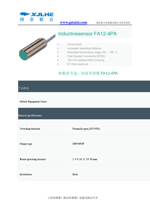
Inductivesensor FA12-4PA•18 mm flush•Increased operating distance•Extended temperature range -40 ... +85 °C•3-pin Deutsch connector (DT04)•100 V/m radiated field immunity•E1-Type approval参数表节选:的技术参数FA12-4PA 产品阐述Mobile Equipment SeriesGeneral specificationsSwitching function Normally open (NC+NO)Output type NPN+PNPRated operating distance2-4-8-10-15-20-30 mmInstallation flush接近传感器电感式传感器电感式接近传感器是大部分应用的首选产品,其范围涉及机械仪器和自动化设备领域的需要高精度、非接触式地检测金属目标物。
作为一个该类产品的市场领导者,倍加福为客户提供创新的高质量的电感式接近传感器以满足世界范围内的自动化和过程控制市场的需求。
我们在该领域有多年丰富经验,工作灵活,处处以客户为尊,根据不同客户的需求提供独特的解决方案。
标准电感式传感器产品特性:•光滑或螺纹式不锈钢圆柱形外壳•反极性保护和短路保护•LED状态指示•M8, M12接插件连接或端子接线方式•PVC,PUR或硅电缆出线方式•2线,3线,4线直流,交流,NAMUR输出方式以及AS-I总线方式输出特殊应用场合电感式传感器特性:•信号输出:4-20 mA 模拟量•集成式速度监控器:达100 Hz•圆柱形高压传感器:最大耐压500 bar•危险区域用传感器:用于气体和粉尘防爆•不锈钢感应面传感器•防护等级最大可达IP68/ IP69k的传感器(能浸入水中/防高压水柱喷射)•防磁防焊系列:表面材质为PTFE•衰减系数为1的传感器:在同一距离可检测所有金属•铁质和非铁金属选择型•安全功能传感器•高温系列:-40 °C 到+250 °C电容式接近传感器电容式接近传感器可检测包含金属在内的几乎所有材质的目标物,在液位、流量控制方面有着广泛应用,检测对象主要为液体,谷类物和粉体等。
FP40R12KT3中文资料
"43
7
"4ZZ 2/>Gb-
3
元器件交易网
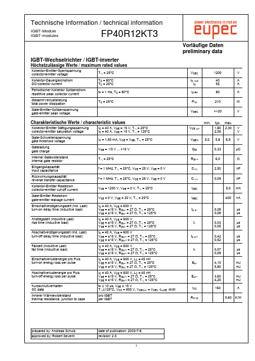
Technische Information / technical information
IGBT-Module IGBT-modules
FP40R12KT3
Vorläufige Daten preliminary data
FP40R12KT3
Vorläufige Daten preliminary data
IGBT-Brems-Chopper / IGBT-brake-chopper
Höchstzulässige Werte / maximum rated values
! ! 1+ 7 ! < < $ # , = "# # ! $ $ $ ! # "# # 1 $ $ $ # %&' ( )*+ %e ( *+ %e ( )*+ 8 ( 0 # 9 %- ( %- ( )*+ *+ ,-./ 2-345 22-:; 7>4> ,@./ # ,-. EF> ,@.>G I@ @K3> D $ ! "# # # ! $ T$ $ # U $ # U U ! V W U U V W W W D # ( 0 MN 9 %&' ( )*+ ,-. ( ) ,9 ,@. ( , ( 0 MN 9 %&' ( )*+ ,-. ( ) ,9 ,@. ( , ,-. ( 0 ,-. ( ,9 ,@. ( ,9 ,@. ( ,9 %&' ( )*+ +KOE +ROE 2-./ 2@./ Y 43 9 S 9 S 9 9 ) 96 9) 9 9 S 09) 90 090 09 H 09 B? )9 09 09S )9 90) 9 090 9 6 )9 6 J J J J J J J J #[ #[ #[ #[ 0 ) AB # C 90) H9) ? , 0 0) ) ,
SIEMENS QFA20室内温湿度传感器 说明书

CE1N1857en Siemens Building Technologies1857室内温湿度传感器QFA20…测量相对湿度和温度工作电压 AC 24 V 或 DC 13.5…35 V 相对湿度输出信号 DC 0...10 V温度输出信号DC 0...10 V 或LG-Ni 1000 或 T1 舒适性湿度范围内的精度达到 ±3 %用途用于通风及空调中来获取房间内的: • 相对湿度,和 • 温度QFA20… 用作 • 控制用的传感器• 楼宇自控系统或者显示单元中的测量用传感器型号一览参考型号温度 测量范围温度 信号输出湿度 测量范围湿度 信号输出工作电压QFA2000 None None0...100 % Active, DC 0...10 V AC 24 V or DC 13.5…35 V QFA2020 0...50 °C Passive, LG-Ni 10000...100 % Active, DC 0...10 V AC 24 V or DC 13.5…35 V QFA2040 0...50 °CPassive, T1 0...100 % Active, DC 0...10 V AC 24 V or DC 13.5…35 V QFA20600...50 °C / −35...+35 °CActive, DC 0...10 V0...100 %Active, DC 0...10 VAC 24 V or DC 13.5…35 V………………………………………………….............1857P 012/5订货订货时,请注明产品名称和参考型号.设备组合所有系统或设备都能够获取和处理传感器的DC 0...10 V 或4...20 mA 、LG-Ni 100 or 或者T1输出信号。
当使用无源温度传感器用作取平均值,我们建议采用SEZ220信号转换器(技术资料N5146)运行模式 传感器通过传感元件的电容值随湿度变化而成函数方式变化来获取风管内的相对湿度值。
641系列清洁空气传感器说明书
641
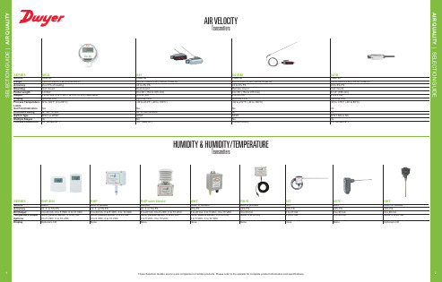
Clean air 250 to 15000 FPM (1.25 to 75 MPS) ±3 to 4% FS Duct mount 6 to 36˝ (152 to 915 mm) 4 to 20 mA Optional LED -40 to 212°F (-40 to 100°C)
WHT
Room or outdoor ±3% FS 4 to 20 mA, 0 to 5 VDC, 0 to 10 VDC None, passive sensor, 4 to 20 mA, 0 to 5 VDC, 0 to 10 VDC None
RH-R
Duct or process ±2% FS 4 to 20 mA None, 4 to 20 mA
None
657
Duct ±2% FS 4 to 20 mA 4 to 20 mA
None
657C
Duct ±2% FS 4 to 20 mA 4
Room or outdoor ±2% FS 4 to 20 mA None, 4 to 20 mA
Optional LCD
No GP SPDT No Consult factory
HUMIDITY & HUMIDITY/TEMPERATURE
Transmitters
641B
Clean air 250 to 2000 FPM (1.25 to 10 MPS) ±5 to 6% FS Duct mount 4-1/4˝ (108 mm) 4 to 20 mA Optional LED -40 to 176°F (-40 to 80°C)
Allegro_建库和封装命名规则

前言器件封装是逻辑和物理的连接体。
所有的设计都是通过PCB来进行连接的。
封装的正确是正确PCB的第一步。
现在的实物封装有很多种,例如我们常见的BGA、QFP、PLCC等。
不同的封装有不同的作用和有缺点。
不同的EDA工具有不同的封装建立保存方法和封装类型。
在CADENCE的设计软件ALLEGRO种主要存在以下五种封装类型文件,每种类型有不同的用处。
1、Package Symbol 、一般元器件封装,例如电阻电容、芯片IC BGA等。
他要求和逻辑设计中的项目标号一一对应。
是逻辑设计在物理设计中的反映。
包含:焊盘文件.pad ,图形文件.dra 、符号文件.psm和Device .txt文件。
2、Mechanical Symbol、主要是结构方面的封装类型。
由板外框及螺丝孔等结构定位器件所组成的结构符号。
包含:图形文件.dra ,和符号文件.bsm有时有必要添加device .txt file。
有时我们设计PCB 的外框及螺丝孔位置都是一样的, 比如显卡, 电脑主板、服务器和同一插筐的不同单板。
每次设计PCB时要画一次板外框及确定螺丝孔位置, 显得较麻烦。
这时我们可以将PCB的外框及螺丝孔建成一个Mechanical Symbol, 在设计PCB 时, 将此Mechanical Symbol 调出即可,这样就节约了时间。
3、Format Symbol、辅助类型的封装(用来处理图形)。
例如:静电标识、常用的标注表格、LOGO等。
主要由图形文件.dra ,和符号文件.osm组成。
是我们设计中不可缺少的一种封装。
4、Shape Symbol、建立特殊焊盘所用的符号。
例如不规则焊盘、金手指焊盘的建立都要将不规则的形状建成个Shape Symbol, 然后在建立焊盘中调用此Shape Symbol。
避免了在焊盘编辑中无法编辑不规则焊盘的局限。
这样,通过ALLEGRO,我们可以设计任何你想要的焊盘形状。
5、Flash Symbol焊盘连接铜皮导通符号, 后缀名为*.fsm。
212操作说明要点
FILGUARD-212 全自动过滤器完整性测试仪FILTER INTEGRITY INSTRUMENT操作手册OP ERATION MANUALSIERWAY上海先维过滤设备厂SHANGHAI SURWAY FILTER FACTORY测试原理一. 气泡点法二. 保压法仪器面板介绍. 面板二. 背板介绍测试准备. 准备工作二. 浸润滤材三. 气路连接仪器操作. 开机二. 预置日期和时间三. 有预置值的自动气泡点测试四. 无预置值的自动气泡点测试五. 保压法测试六. 手动气泡点测试七. 自检八. 气流调节故障排除性能参数维护保养随机附件可选附件1011 11 12 12 13 13 13FILGUARD-212型全自动过滤器完整性测试仪1FILGUARD-212型过滤器完整性测试仪适用于对过滤器进行完整性检测,判断过滤器的密封性是否完好、滤材有无破损以及选用的滤材过滤精度是否符合要求,以保证过滤器能按要求正常运行。
FILGUARD-212型测试仪是由微电脑控制的自动测试仪,应用经典的气泡点法和压力保持法(扩 散流法的衍生方法)测试原理,能自动测试过滤器的完整性,测试精度高,操作简单方便,且所有的测试过程都在过滤器的上游进行, 对过滤器的下游无污染, 尤其适用于除菌过滤器的检测。
过滤器测试仪广泛运用于医药、生物工程、食品饮料、微电子等行业,也是过滤器制造商进行 过滤器检测的常规仪器。
测试原理.气泡点法 当滤材被液体(湿润液)浸润后,在滤材的两侧加上气体压差,由于毛细管效应,气体要将毛 细管中的液体赶走而冒出气泡,气体的压差必须增大到某一值 也P ,这个压差值就称为气泡点,其计 算公式如式1。
式1表明,孔径愈小,气泡点愈高,因此可以用气泡点来检测过滤器的性能。
仲=4 0' cos8/ D 其中: 妒一压差(达因/厘米2) U —表面张力 •浸润液与滤材的接触角 D —孔径(厘米) .保压法 滤材被液体(湿润液)浸润后,在滤材的两侧加上气体压差, 并使滤材上游成为一个密闭的气压腔,所加的压差值略小于滤材的气泡点(一般设定在气泡点的 80%),这时气体不能在滤材的毛细孔中直接流通,但气体分子可以通过毛细孔中的液体扩散至下游, 这种由于气体扩散而形成的气体流量称为扩散流。
Mitsubishi MELSEC iQ-F Series PLC产品介绍说明书

MELSEC iQ-F SeriesiQ Platform-compatible PLC The next level of industryWitness the evolution of the micro PLC.Designed on the concepts of outstanding performance, superior drive control, and user centric programming,Mitsubishi's MELSEC-F Series has been reborn as the MELSEC iQ-F Series. The next level of industryFrom stand alone use to networked system application,MELSEC iQ-F Series brings your business to the next level of industry.The next level of industryNew micro PLC designed on the concepts of ...Outstanding Performance Environment- Completely redesigned, high speed system bus- Extensive built-in functions - Enhanced security functions- Built-in positioning (4-Axis 200 kHz)- Simple linear interpolation (2-Axis simultaneous start)- Synchronous control with Simple Motion unit (4-Axis)- No need for dedicated positioning software- Easy programming by drag and drop - Reduced development time with module FB- Parameterized setup for a variety of functions3iQ Platform for maximum return on investmentMinimize Total cost, Seamless integration, Maximize productivity, Transparentcommunications: these are common items that highlight the benefits of the iQ Platform. Enhanced further with the arrival of the new MELSEC iQ-F Series Programmable Logic Controller (PLC), reducing costs and improving productivity can be realized even easier.The iQ Platform minimizes TCO at all phases of the automation life cycle by improving development times, enhancing productivity, reducing maintenance costs, and making information more easily accessible.PLC & HMI1. The new MELSEC iQ-F Series system bus is 150-times faster realizing improved system performance2. Program standardization through function blocks and module labels3. Powerful and robust security featuresNetwork1. CC-Link IE Field, 1Gbps high-speed and large bandwidth communications network2. Seamless connectivity within all levels of manufacturing with SLMPEngineering1. Automatic generation of network configuration diagram2. Share parameters across multiple engineering software via MELSOFT Navigator4PLC & HMINetworkEngineering environmentERP (Enterprise resource planning)MES (Manufacturing execution system)Transparent connectivity56Built-in RS-485(MODBUS®) CommunicationFor related systems and data transfer with external equipment and third party devices, serial communication has long been the established connection method. Serial communication allows the FX 5U to connect both e ciently and reliably with other PLCs, sensors, printers, and modems, etc. Multi-drop networks, non-protocol communication, and remote maintenance are just some of the many uses.No need for additional options for RS-485 communicationThe run/stop switch conveniently includes the same reset functionality found on high end devices.PLC can be rebooted without turning o the main power for e cient debugging.RUN/STOP/RESET Switch7Built-in Ethernet portEasy parameter setting›› MODBUS/TCP clientIn the information age, Ethernet has become the personal, commercial and industrial standard for easy and e cient data transfer. Whether it is between multiple PLC systems or PLC and PC servers, industrial users dictate foremost that data must always be consistent even in high-noise environments.Device data read-out/writing to a PLC from Built-in Ethernet supporting 8 chProgram read/write can be made by ›› Remote Maintenance›› SLMP Communication›› Socket CommunicationCC-Link IE slave ModuleSSCNET Ⅲ/HThe MELSEC iQ-F high speed system bus provides seamless data transfer from/to the CPU.With new architecture that realizes data speeds of 1.5 k words per ms (150-times faster than FX 3U ), fast response is guaranteed even when using expansion modules.access.High-speed System BusSecurity... Future support8The built-in high-speed pulse inputs and outputs on the FX5U, with special positioningoperations instructions, are designed to satisfy simple independent-axis positioningapplications using servo and stepping motors with speed and precision.Positioning operations on di erent axes can also be started simultaneously. Simple Motion Module(4-Axis module)Built-in Positioning (4-Axis built-in)Pulse OutputON (Forward Rotation)DirectionOFF (Reverse Rotation)Simple Linear interpolation (2-Axis simultaneous start)Basic Positioning ControlFX5-40SSC-SxyStart pointTarget position(x,y)X coordinateY coordinatePositioning control is easily executed using a point table.The machine can coat the workpiece by using a combination of linear interpolation, 2-Axiscircular interpolation, and continuous trajectory control.A smooth trajectory can be traced with the S-curve acceleration/deceleration function.Application examples• Sealing• DispensersMain functions• Continuous trajectory control• Linear interpolation• Circular interpolation• S-curve acceleration/deceleration1. X-Axis2. Y-Axis3. Z-AxisFX5U-32M : 6 ch 200 kHz+2 ch 10 kHzPositioning SolutionThe next level of industry Parameter settings,Mark detection10Engineering EnvironmentGX Works3 consists of various different components that help to simplify project creation and maintenance tasks. A system design console that enables projects to be created at the system overview stage has been added.System design with a convenient parts libraryMost projects start from system design, so having a software application that caters to this initial stage is important. GX Works3 incorporates a system design feature that enables system components to be assembled directly in the programming software. It includes a parts library consisting of MELSEC iQ-F Series modules that can be used to simplify system creation.Drag & DropSimply drag & drop when adding a moduleRegister module parameters on the flyAnother useful feature is the ability to register parameters automatically. Simply double-click on the desired module and the corresponding parameters will be registered in the project. A window with an easy-to-use parameter settings screen opens, enabling module parameters to be modified as needed.Parameters automatically added to navigation paneDouble click11The next level of industryGlobal label editorIntegrated motion setup toolGX Works3 is equipped with a special motion setup tool that makes it easy to change simple motion module settings such as module parameters, positioning data and servo parameters. Also, the servo adjustment is simplified using it.Reduce repetitive program tasksGlobal and local variables (labels) are supported providing an easy way to share device names across multiple projects, other MELSOFT software and third party SCADA. The variables can be registered into either the current program, function block as a local variable or within the project as a global variable to share across multiple programs within the same project. Variables specific to a particular module are also available, and can be used immediately, further reducing engineering time and cost.Main programming languages supportedThe main IEC languages are supported by GX Works3. Various different programming languages can be used within the sameproject simultaneously and can be viewed easily via the menu tab. The variables and devices used in each program can be shared across multiple platforms, with user defined function blocks supported.Structured textSynchronous Control Parameter System con guration Digital oscilloscope121314CPU module specificationcNumber of device points[2 : Total of the index register (Z) and long index register (LZ) is maximum 24 words.[1 : The retention period of a fully charged capacitor (electricity is conducted across the PLC for at least 30 minutes) is 10 days (ambient temperature: 25°C (77°F)).[1 : The simultaneous ON ratio of available PLC inputs or outputs changes with respect to the ambient temperature, refer to manuals of each product.[2 : For details on Intelligent function modules, refer to manuals of each product.[3 : The criterion is shown in IEC61131-2.[4 : Ground the PLC independently or jointly.[5 : The PLC cannot be used at a pressure higher than the atmospheric pressure to avoid damage.[6 : This index indicates the degree to which conductive material is generated in the environment in which the equipment is used.Pollution level 2 is when only non-conductive pollution occurs. Temporary conductivity caused by condensation must be expected occasionally.[1 : This value is for when all 24 V DC service power supplies are used in the maximum configuration in which they can beconnected to the CPU module. The input current is included.[2 : When I/O modules are connected, they consume current from the 24 V DC service power.The next level of industry c Output Specifications[1 : Number of stages that can be connected when a repeater hub is used. When a switching hub is used, check the specificationsof the switching hub used.[2 : A straight cable can be used. If a personal computer and CPU module are directly connected (simple connection), a cross cablecan be used.c Input Specifications[1 : "Digit" refers to digital values.[1 : "Digit" refers to digital values.1516Simple motion module specificationcModule specificationcControl specification[1 : 4-axis linear interpolation control is enabled only at the reference axis speed.[2 : 8 ch word data and 8CH bit data can be displayed in real time.17The next level of industryExternal DimensionsMain ModulesExpansion ModulesExpansion Adapters FX5-232ADP / FX5-485ADPI/O ModulesIntelligent Function ModuleExtension Power Supply ModuleFX5-CNV-BUSBus Conversion Module 8 (0.32")83 (3.27")• Exterior color : Main body: Munsell 0.6B7.6/0.2• Accessories : Dust proof protection sheet, Manual supplied with productFX5-40SSC-SFX5-1PSU-5VUnit: mm (inches)Unit: mm (inches)Products list1819The next level of industryh Ethernet is a trademark of Xerox Corporation.h MODBUS is a registered trademark of Schneider Electric SA.h All other company names and product names used in this document are trademarks or registered trademarks of their respective companies.About this product catalogDue to the constantly growing product range and new or changed product features, the information in this catalog may be updated without notice. Please contact your Mitsubishi Electric product provider for more details.Texts, figures and diagrams shown in this product catalog are intended exclusively for explanation and assistance in planning and ordering the FX5 programmable logic controllers (PLCs) and the associated accessories. Only the manuals supplied with the units are relevant for installation, commissioning and handling of the units and the accessories. The information given in the manuals must be read before installation and commissioning of the units or software.If any questions arise regarding the application or use of the PLC units and accessories described in this catalog, please contact your Mitsubishi Electric product provider.This catalog confers no industrial property rights or any rights of any other kind, nor does it confer any patent licenses. Mitsubishi Electric Corporation cannot be held responsible for any problems involving industrial property rights which may occur as a result of using the contents noted in this catalog.©2014 MITSUBISHI ELECTRIC CORPORATIONHEAD OFFICE: TOKYO BLDG., 2-7-3, MARUNOUCHI, CHIYODA-KU, TOKYO 100-8310, JAPAN PROGRAMMABLE CONTROLLERSHIME-L081-A1411(MEE)New publication, effective Nov. 2014 Specifications subject to change without notice.。